c series pneumatic rack & pinion rotary actuatorsallied-flow.com/files/c-act0208-full2.pdf ·...
TRANSCRIPT

C Series Pneumatic Rack & Pinion Rotary Actuators -SpringReturn&DoubleActing-
Features and Benefits
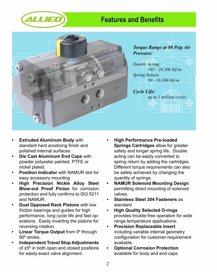
Extruded Aluminum Body • with standard hard anodizing finish and polished internal surfacesDie Cast Aluminum End Caps • with powder polyester painted, PTFE or nickel plated.Position Indicator • with NAMUR slot for easy accessory mountingHigh Precision Nickle Alloy Steel •Blow-out Proof Pinion for corrosion protection and fully confirms to ISO 5211 and NAMUR.Dual Opposed Rack Pistons • with low friction bearings and guides for high performance, long cycle life and fast op-erations. Easily inverting the pistons for reversing rotation.Linear Torque Output • from 0º through 90º stroke.Independent Travel Stop Adjustments •of ±5º in both open and closed positions for easily exact valve alignment.
High Performance Pre-loaded •Springs Cartridges allow for greater safety and longer spring life. Double acting can be easily converted to spring return by adding the cartridges. Different torque requirements can also be safely achieved by changing the quantity of springs.NAMUR Solenoid Mounting Design •permitting direct mounting of solenoid valves.Stainless Steel 304 Fasteners • as standardHigh Quality Selected O-rings •provides trouble-free operation for wide range temperature applications.Precision Replaceable Insert •including variable internal geometry configuration for customer requirement available.Optional Corrosion Protection• available for body and end caps.
2
Torque Range at 80 Psig Air Pressure: Double Acting: 195 - 28,500 lbf-inSpring Return: 50 - 16,500 lbf-in
Cycle Life: up to 1 million cycles

OperationsDouble Acting
By supplying air to Port A, pressure is applied to the center chamber and forces the dual pistons outward. Linear piston force is transferred via gear racks to the pinion gear, causing the pinion to turn counterclock-wise while the air is being exhausted from Port B.
By supplying air to Port B, pressure is applied to the outside chamber and drives the dual pistons inward. The action causes the pinion to turn clockwise while the air is being exhausted from Port A.
Spring Return
By supplying air to Port A, pressure is applied to the center chamber, forces the dual pistons outward and compresses the springs in the outside chambers and produce counterclockwise rotary. Exhaust air exits at Port B.
Upon loss of air pressure, the stored energy in the compressed springs forces the pistons inwards pro-ducing rotary motion with exhaust air exiting at Port A. This “fail safe” position is held by spring force until air pressure reapplied to Port A.
Installation of Springs for Spring Return Actuator
3
Even spring set is recommended for high cycle application.

Materials of Construction
No. Part Description Material Qty. No. Part Description Material Qty.
1 Indicator Cap Screw Plastic/Stainless Steel 1 15 Spring (Cartridge) High Alloy Spring Steel 0-12
2 Position Indicator Plastic (ABS) 1 16 Bearing (Piston) Ployoxymethylene 2
3 Pinion Snap Ring Stainless Steel 300 Series 1 17 O-ring (Piston) NBR 2
4 Thrust Washer Stainless Steel 300 Series 1 18 Piston Die-Cast Aluminum 2
5 Thrust Bearing Polyoxymethylene 1 19 Plug NBR 2
6 Body Extruded Aluminum Alloy (6005-T5) 1 20 O-ring (Adjusting Screw) NBR 2
7 Piston Guide Polyoxymethylene 2 21 Stop Nut (Adjusting Screw) Stainless Steel 300 Series 2
8 O-ring (Pinion Top) NBR 1 22 Adjusting Screw Stainless Steel 300 Series 2
9 Bearing (Pinion Top) Polyoxymethylene 1 23 Stop Screw Stainless Steel 300 Series 2
10 Inside Washer Polyoxymethylene 1 24 Nut (Stop Screw) Stainless Steel 300 Series 2
11 Cam Stainless Steel 300 Series 1 25 O-ring (End Cap) NBR 2
12 Pinion (Drive Shaft) Stainless Steel 300 Series 1 26 End Cap Die-Cast Aluminum 2
13 Bearing (Pinion Bottom) Polyoxymethylene 1 27 End Cap Screw Stainless Steel 300 Series 8
14 O-ring (Pinion Bottom) NBR 1 28 Shaft Adapter Sintered Metal 1
4

Dimensions
No. Part Description Material Qty. No. Part Description Material Qty.
1 Indicator Cap Screw Plastic/Stainless Steel 1 15 Spring (Cartridge) High Alloy Spring Steel 0-12
2 Position Indicator Plastic (ABS) 1 16 Bearing (Piston) Ployoxymethylene 2
3 Pinion Snap Ring Stainless Steel 300 Series 1 17 O-ring (Piston) NBR 2
4 Thrust Washer Stainless Steel 300 Series 1 18 Piston Die-Cast Aluminum 2
5 Thrust Bearing Polyoxymethylene 1 19 Plug NBR 2
6 Body Extruded Aluminum Alloy (6005-T5) 1 20 O-ring (Adjusting Screw) NBR 2
7 Piston Guide Polyoxymethylene 2 21 Stop Nut (Adjusting Screw) Stainless Steel 300 Series 2
8 O-ring (Pinion Top) NBR 1 22 Adjusting Screw Stainless Steel 300 Series 2
9 Bearing (Pinion Top) Polyoxymethylene 1 23 Stop Screw Stainless Steel 300 Series 2
10 Inside Washer Polyoxymethylene 1 24 Nut (Stop Screw) Stainless Steel 300 Series 2
11 Cam Stainless Steel 300 Series 1 25 O-ring (End Cap) NBR 2
12 Pinion (Drive Shaft) Stainless Steel 300 Series 1 26 End Cap Die-Cast Aluminum 2
13 Bearing (Pinion Bottom) Polyoxymethylene 1 27 End Cap Screw Stainless Steel 300 Series 8
14 O-ring (Pinion Bottom) NBR 1 28 Shaft Adapter Sintered Metal 1
MODEL A B C D E F G H J K L M R S T U
C-DA/SR52 5.79 1.18 1.63 1.58 2.56 2.58 2.83 3.62 3.15 1.18 0.55 0.43 M5×8 M6×10 F03/1.417 F05/1.969
C-DA/SR63 6.61 1.42 1.85 1.58 2.83 3.19 3.44 4.23 3.15 1.18 0.71 0.55 M6×10 M8×13 F05/1.969 F07/2.756
C-DA/SR75 7.24 1.65 2.09 1.58 3.19 3.70 3.92 4.70 3.15 1.18 0.71 0.55 M6×10 M8×13 F05/1.969 F07/2.756
C-DA/SR83 8.03 1.81 2.24 1.58 3.62 3.88 4.28 5.07 3.15 1.18 0.83 0.67 M6×10 M8×13 F05/1.969 F07/2.756
C-DA/SR92 10.31 1.97 2.30 1.58 3.86 4.37 4.60 5.39 3.15 1.18 0.83 0.67 M6×10 M8×13 F05/1.969 F07/2.756
C-DA/SR105 10.55 2.26 2.52 1.58 4.31 4.82 5.24 6.02 3.15 1.18 1.02 0.87 M8×13 M10×16 F07/2.756 F10/4.016
C-DA/SR125 11.65 2.66 2.93 2.17 5.02 5.73 6.10 6.89 5.12 1.18 1.02 0.87 M8×13 M10×16 F07/2.756 F10/4.016
C-DA/SR140 15.35 2.95 3.03 2.17 5.41 6.33 6.75 7.54 5.12 1.18 1.22 1.06 M10×16 M12×20 F10/4.016 F12/4.921
C-DA/SR160 18.03 3.43 3.43 2.17 6.22 7.24 7.76 8.54 5.12 1.18 1.22 1.06 M10×16 M12×20 F10/4.016 F12/4.921
C-DA/SR190 20.79 4.06 4.06 3.15 7.44 8.50 9.06 9.84 5.12 1.18 1.57 1.42 M16×25 F14/5.512
C-DA/SR210 22.20 4.45 4.45 3.15 8.27 9.27 10.04 10.83 5.12 1.18 1.57 1.42 M16×25 F14/5.512
C-DA/SR240 23.70 5.12 5.12 3.15 9.65 10.39 11.34 12.13 5.12 1.18 1.97 1.81 M20×25 F16/6.496
C-DA/SR270 27.80 5.79 5.79 3.15 10.75 11.77 12.83 13.62 5.12 1.18 1.97 1.81 M20×25 F16/6.496
5

Technical DataSpring Return Actuators Output Torque (lbf-in)
0° 90° 0° 90° 0° 90° 0° 90° 0° 90° 0° 90° 0° 90° 90° 0°
55 37 77 58 55 3848 24 70 46 924 78 66 4539 13 61 34 90 67 120 89 77 52
53 20 84 55 113 78 140 114 87 6044 8 76 44 105 67 133 104 160 132 98 67
68 33 98 57 126 94 153 122 109 7560 21 91 46 119 84 146 113 172 140 120 82
83 36 112 74 139 95 166 130 131 90111 75 153 116 204 137 92 6198 55 138 95 191 152 242 205 111 7284 35 127 73 179 133 229 187 129 85
111 52 167 114 218 169 267 220 315 269 148 97154 95 206 151 255 203 304 253 166 10913 75 195 133 244 186 293 236 341 286 185 121
184 115 234 169 283 220 330 270 203 133171 97 222 152 271 204 320 254 222 145
141 103 197 158 270 235 128 93121 74 176 128 251 208 321 280 154 112101 47 155 99 232 182 303 256 179 131
133 69 211 155 284 231 352 301 418 369 205 149192 129 266 206 335 278 402 347 231 168174 102 246 181 318 254 386 324 451 391 256 187
231 157 301 231 369 301 435 369 282 205213 132 284 207 353 278 419 346 308 224
227 157 317 244 428 364 204 140196 112 285 196 400 321 508 434 244 168166 67 252 151 371 279 481 395 285 196
221 103 342 237 454 355 560 466 663 572 326 224313 195 426 316 534 429 638 536 367 252284 152 400 276 508 391 613 500 715 605 407 280
373 237 483 353 588 464 691 570 448 308345 198 456 316 563 428 667 536 489 336
322 214 450 338 612 511 304 207277 148 403 269 569 449 725 612 365 248231 80 355 197 526 385 685 553 426 289
319 128 484 323 646 495 799 655 947 808 487 331441 260 606 436 761 599 911 755 548 372399 197 566 377 723 543 874 700 1022 853 608 413
525 318 685 487 837 647 986 801 669 454486 260 647 432 800 593 950 749 730 496
497 325 687 508 921 760 436 280435 229 622 407 862 670 1088 908 523 336374 133 559 308 805 580 1035 824 610 392
494 208 747 490 980 740 1203 974 1419 1198 697 448689 400 927 656 1152 894 1370 1122 784 504631 306 872 569 1100 811 1320 1041 1535 1264 871 560
818 487 1048 733 1270 966 1486 1191 958 616764 406 997 656 1221 892 1439 1119 1045 672
40
C-SR52
C-SR63
C-SR75
C-SR83
C-SR92
C-SR105
6

Technical Data
Continued
7
0° 90° 0° 90° 0° 90° 0° 90° 0° 90° 0° 90° 0° 90° 90° 0°
712 453 1000 729 1358 1115 698 462610 305 893 574 1263 976 1608 1340 832 555509 148 787 410 1167 828 1519 1202 971 647
681 255 1071 689 1429 1072 1770 1429 2100 1772 1110 740976 541 1340 934 1685 1298 2018 1645 1249 832880 402 1251 804 1600 1174 1936 1526 2264 1865 1387 925
1161 666 1514 1043 1854 1399 2184 1742 1530 10171072 536 1429 919 1772 1280 2105 1626 1665 1110
1246 823 1737 1296 2346 1948 1143 7591082 573 1566 1035 2192 1713 2778 2331 1370 908916 324 1392 773 2035 1478 2631 2112 1598 1059
1218 512 1878 1244 2485 1892 3063 2498 3624 3080 1826 12111713 1009 2331 1673 2916 2290 3483 2879 2054 13701557 765 2185 1446 2777 2073 3348 2670 3906 3247 2283 1522
2039 1226 2638 1864 3214 2468 3776 3051 2510 16731892 1007 2498 1655 3080 2267 3645 2855 2741 1824
1877 1212 2640 1943 3592 2966 1844 12361609 805 2359 1518 3340 2583 4256 3549 2212 14831332 398 2069 1093 3079 2200 4012 3192 2581 1730
1789 667 2826 1818 3777 2022 4680 3782 5556 4691 2949 19772566 1435 3533 2477 4448 3442 5332 4363 3321 22252313 1052 3297 2120 4223 3102 5116 4034 5986 4935 3691 2472
3062 1771 3999 2769 4900 3714 5776 4624 4056 27192818 1413 3767 2429 4676 3386 5559 4305 4422 2966
3228 2164 4457 3345 5957 4957 2737 17742839 1563 4051 2717 5592 4392 7041 5921 3287 21272451 962 3645 2088 5227 3827 6700 5393 3834 2480
3239 1460 4861 3261 6359 4865 7789 6366 9180 7808 4380 28334496 2696 6018 4337 7464 5863 8867 7323 4927 31864131 2131 5677 3809 7139 5360 8554 6838 9936 8269 5473 3540
5336 3281 6814 4858 8240 6354 9632 7798 6020 38934995 2753 6490 4355 7927 5869 9327 7327 6566 4246
3801 2774 5327 4254 7227 6262 3363 24303265 2035 4767 3481 6723 5566 8552 7472 4036 29172728 1295 4206 2707 6218 4870 8081 6822 4708 3405
3645 1934 5714 4174 7610 6172 9413 8044 11164 9844 5381 38935209 3479 7139 5523 8965 7426 10731 9247 6053 43804705 2783 6668 4873 8516 6807 10299 8651 12038 10436 6726 4868
6197 4223 8068 6188 9866 8054 11617 9856 7399 53565726 3574 7619 5569 9434 7457 11197 9276 8071 5843
5373 3977 7571 6111 10332 9018 4902 36324578 2895 6739 4979 9584 8001 12239 10761 5885 43553773 1822 5898 3858 8827 6992 11533 9819 6861 5087
5066 2727 8079 5975 10834 8869 13451 11579 15989 14184 7844 58107323 4957 10128 7919 12778 10674 15340 13312 8828 65416575 3948 9429 6976 12113 9777 14699 12446 17220 15031 9803 7264
8731 6026 11448 8872 14057 11574 16596 14183 10787 79878024 5076 10775 7967 13408 10701 15966 13335 11771 8719
8786 6576 12163 9852 16289 14210 6961 49527695 5050 11022 8257 15263 12775 19256 16934 8349 59446612 3514 9891 6652 14245 11332 18306 15585 9744 6928
8750 5057 13219 9897 17348 14245 21286 18332 25109 22260 11132 792012193 8453 16389 12897 20374 17048 24229 21023 12527 891211167 7018 15431 11557 19461 15771 23349 19792 27156 23699 13914 9904
14473 10209 18548 14487 22469 18554 26300 22496 15310 1089613523 8869 17643 13211 21597 17324 25452 21300 16697 11880
C-SR125
40
C-SR240
C-SR270
C-SR140
C-SR160
C-SR190
C-SR210

Technical Data
AIR PRESSURE (Psig)MODEL 40 50 60 70 80 90 100 110 120C-DA52 97 122 146 171 195 219 244 268 292C-DA63 178 223 267 313 356 401 446 490 535C-DA75 245 306 368 430 490 551 613 674 735C-DA83 383 476 574 671 766 861 957 1053 1149C-DA92 551 689 827 967 1103 1240 1378 1516 1654
C-DA105 808 1009 1211 1416 1615 1817 2019 2221 2423C-DA125 1225 1532 1833 2149 2450 2757 3063 3369 3676C-DA140 2088 2611 3133 3662 4177 4699 5221 5743 6265C-DA160 3249 4061 4873 5697 6497 7309 8122 8934 9746C-DA190 5198 6497 7797 9115 10396 11695 12995 14294 15594C-DA210 6497 8122 9746 11394 12995 14619 16243 17868 19492C-DA240 9398 11753 14097 16480 18796 21151 23495 25850 28194
C-DA270 14282 17856 21430 25046 28565 32139 35712 39286 42859
Double Acting Actuators Output Torque (lbf-in)
MODEL 52 63 75 83 92 105 125 140 160 190 210 240 270
C-DA 3 4 6 7 10 13 19 25 36 70 76 106 163
C-SR 3 4 6 7 12 14 22 29 44 78 85 135 216
Weight (lbs)
ModelAction 52 63 75 83 92 105 125 140 160 190 210 240 270
CCW 7.3 12.9 18.3 26.2 39.1 58.0 97.6 152.5 225.7 359.9 457.5 671.2 1037.5
CW 9.7 14.1 20.7 28.7 44.6 53.7 85.4 134.2 195.2 329.4 457.5 549.3 854.4
Maximum Air Consumption (cu. inches) Per Stroke
ModelSpeed
Action52 63 75 83 92 105 125 140 160 190 210 240 270
CCWDA 0.3 0.5 0.5 0.5 0.6 0.8 0.9 1.2 1.5 2.2 2.8 3.5 3.5
SR 0.4 0.6 0.6 0.6 0.7 1.0 1.1 1.4 2.0 2.5 3.5 4.2 4.5
CWDA 0.4 0.6 0.6 0.7 0.8 1.0 1.2 1.5 1.8 2.5 3.5 4.2 4.5SR 0.4 0.8 1.0 1.0 1.2 1.2 1.5 1.8 2.5 3.0 4.0 5.0 6.0
Actuator Cycle Speed (sec.)
Speed measured at 80 psig air without valve, resistant part, and exhaust air fitting. Cycle speed greatly increases in actual application.
8

Specifications
Operating Media: Dry and lubricated air, or non-corrosive gas. The maximum particle diameter must be less than 30 μm.Air Supply Pressure: The minimum supply pressure is 35 psig. The maximum supply pressure is 150 psig.Operating Temperature: Standard (NBR O-ring): -4 OF to 175 OF. Low Temperature (Silicone O-ring): -30 OF to 175 OF. High Temperature (Viton O-ring): 5 OF to 300 OF.Stroke Adjustment Stops allow adjustment range of ±5O for the rotation at 0O and 90O positions.Application: Both Indoor and Outdoor.
Operating Conditions
Drive and Flange to ISO 5211 configuration for easy direct mount onto a valve or connec-tion with standardized mounting hardware.
The NAMUR Drive Pinion and NAMUR top mounting connec-tion for direct installation of accessories such as Limit Switch and Positioner.
Air supply connection is designed in accordance with NAMUR Standard to install solenoid valve
9
Electroless Nickel Plating Infused Housing Actuators Provide an effective corrosion resistant Application
Different colors powder polyester painted
and treatment body and ends available.
Interface Specification
Body and End Finish
Stroke Adjustment

Double Acting Actuators
As shown in the figure, the output torque of double acting actuator is constant in both clockwise and counterclockwise rotation. Actuator can be sized by using steps as follow:
Obtain the published maximum valve torque• Add recommended safety factor (margin) to the published torque to get • the required operating torque. The suggested safety factor for Double Acting Actuator in normal working conditions is at least 20%.Refer to the table of Double Acting Actuator Output Torque above, use • the Air Supply Pressure to find the torque that greater than the required operating torque.Check the table Model item to determine the appropriate actuator. •
Example:
A published highest seating/unseating torque for a 8” high performance butterfly is 2600 lbf-in; the hydrodynamic • torque for 2 psi pressure drop is 500 lbf-in. The maximum valve torque is 2600 + 500 = 3100 lbf-in The required operating torque equals to 3100 + 3100 x 20% = 3720 lbf-in• Known Air Supply Pressure 80 psig, the first actuator torque that exceeds to the required torque is 4177 lbf-in • From the table, the selected double acting actuator model is C-DA140. •
Spring Return Actuators
The output torque of spring return actuator is obtained by two operation - Air Stroke and Spring Stroke. Each stroke produces two different values in the operation end position “Start” or “End” shown in the right figures. The four values are used for sizing the actuator.
Obtain the published maximum valve torque in work conditions.• Add recommended safety factor (margin) to the published torque to get • the required operating torque. The suggested safety factor for Spring Return Actuator in normal working conditions is 10%.Refer to the table of Spring Return Actuator Output Torque above, use • the Air Supply Pressure to locate the Air End torque greater than the required operating torque.Move the table Spring Return Output column. Check the Spring End • torque if it exceeds the required torqueRead left cross the table to locate the Spring Numbers and Actuator • Model to determine the appropriate actuator size and spring numbers
Example:
Given a maximum published torque for a 2” flanged valve in full differential pressure is 400 lbf-in • The required operating torque is 400 + 400 x 10% = 440 lbf-in• Given Air Supply Pressure is 80 psig, find the Spring Return actuator both Air End torque (487 lbf-in) and Spring • End torque (454 lbs-in) values exceeding to the required torque (440 lbf-in) Cross the table to the left, the selected Spring Return actuator model is C-SR92-11. •
0° 90°
Torq
ue
Start End
Double Acting Torque Curve
0° 90°
Start
End
Double Acting Torque CurveTo
rque
0° 90°
Start
End
Torq
ue
Air Stroke
Spring Stroke
10
Actuators Sizing Guide

Other Series of Actuators
A Series ActuatorStainless Steel Body, Pinion, Pistons and FastenersModel A-DA/SR46-160Torque: up to 6500 lbf-in for DA 3600 lbf-in for SR
B Series ActuatorAluminum Body, Ends, WideRange of SelectionModel B-DA32-400, SR45-400Torque: up to 78000 lbf-in for DA 63700 lbf-in for SR
Special Stroke and 3-Position Actuatorsare also available
How To Order
Series Type Model Spring Qty. Seals Option Color Code Coating
C SR - Spring ReturnDA - Double Acting
5263758392
105125140160190210240270
56789
101112
N - NBRS - Silicone
V - Viton
FO - Fail Open180 - 180O Operation
X - Special (B-) Body Color(E-) End Color
11
Allied Flow can also provide valve automation accessories, including Limit Switches, Positioners, Solenoid Valves, and Mounting Hardware.
All actuators are manufactured in a registered ISO 9001-2000 facility• All actuators are 100% inspected and tested in factory• Each actuator is marked with a unique serial number for full traceability• .
Quality Assurance
Ordering Information
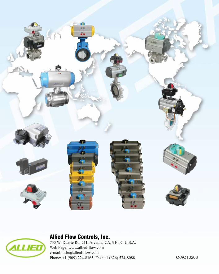
Allied Flow Controls, Inc.735 W. Duarte Rd. 211, Arcadia, CA, 91007, U.S.A. Web Page: www.allied-flow.come-mail: [email protected]: +1 (909) 224-8165 Fax: +1 (626) 574-8088 C-ACT0208