c naval applications
TRANSCRIPT

Naval Applications and Research & DevelopmentAccording to a study prepared for the U.S. Navy in 1988, the military has been employingcomposite materials effectively for many years and has an increasing number of projects andinvestigations under way to further explore the use of composites. [1-1] In 1946, the Navy lettwo contracts for development of 28 foot personnel boats of laminated plastic. WinnerManufacturing Company used a “bag molding” method while Marco Chemical employed an“injection method.” The Navy used the second method for some time with limited successuntil about 1950 when production contracts using hand lay-up were awarded. Between 1955and 1962, 32 Navy craft from 33 to 50 feet in length were manufactured by the “core mold”process, which proved not to be cost effective and was structurally unsatisfactory. [1-25]
During the 1960s, the Navy conducted a series of studies to consider the feasibility of using anFRP hull for minesweepers. In 1969, Peterson Builders, Inc. of Sturgeon Bay, WI completed a 34foot midship test section. A complete design methodology and process description was developedfor this exercise. Although the scale of the effort was formidable, questions regarding economicsand material performance in production units went unanswered. [1-26]
Submarines
During the Cold War period, the Navy had an aggressive submarine research and developmentprogram that included the investigation of composites for interior and exterior applications.Both these environments were very demanding with unique sets of performance criteria thatoften pushed the envelope of composites design and manufacturing. The rigors of submarinecomposites design made partnership with this country's finest aerospace companies a likelymatch. For surface ship applications, the aerospace approach is generally perceived to not becost effective.
Submarine ApplicationsVarious submarine structures are made of composite materials, including the periscope fairings onnuclear submarines and the bow domes on combatant submarines. Additionally, the use offilament-wound air flasks for the ballast tanks of the Trident class submarines has beeninvestigated. Unmanned, deep submersibles rely heavily on the use of composites for structuralmembers and for buoyancy. Syntactic foam is used for buoyancy and thick-walled composites areused for pressure housings. One unmanned deep sea submersible, which has a depth rating of20,000 feet, is constructed with graphite composite by the prepreg fabrication technique. [1-1]
Periscope fairings have been built of FRP since the early 1960s by Lunn Industries. Theseautoclave-cured parts are precision machined to meet the tight tolerances required of theperiscope bearing system. The fairings are all glass, with a recent switch from polyester toepoxy resins. The two-piece fairing is bolted around a metal “I-beam” to form the structuralmast. An RTM manufacturer, ARDCO of Chester, PA is currently investigating the feasibilityof building the entire structure as a monolithic RTM part, thereby eliminating the metal“I-beam” and bolted sections. Carbon fiber unidirectionals will be added to the laminate tomatch the longitudinal stiffness of the incumbent structure.
26
Naval Applications of Composites Marine Composites

Another Navy program which employs composite materials is theWet Sub. Its compositecomponents have proven reliable for over 15 years. Both the elevator and the rudders areconstructed of a syntactic foam core with fiberglass and polyester skins. The outer skin andhatches, the tail section and the fixed fins on theWet Subare also made of composite materials.
The Navy's ROV and mine hunting/neutralization programs have been using composite materialsfor structural, skin and buoyancy applications. Current ROVs employ composite skins and framesthat are constructed from metal molds using the vacuum bagging process.
The propellers for the MK 46 torpedo are now being made of composite materials. Moldedcomposite propeller assemblies have replaced the original forged aluminum propellers. Thecomposite propellers are compression molded of glass fiber reinforced polyester resin. Advantages ofthe new composite propellers include weight savings, chemical inertness and better acousticproperties. Elimination of the metal components markedly reduces delectability. Additionally,studies have projected this replacement to have saved the program a substantial amount of money.
A submarine launched missile utilizes a capsule module that is constructed of compositematerials. The capsule design consists of a graphite, wet, filament-wound sandwichconstruction, metal honeycomb core and Kevlar® reinforcements. Several torpedo projectshave investigated using a shell constructed of composites, including a filament-wound carbonfiber composite in a sandwich configuration where the nose shell of the torpedo wasconstructed with syntactic foam core and prepreg skins of carbon and epoxy resin. Testingrevealed a reduction in noise levels and weight as compared to the conventional aluminumnose shell. Research at NSWC, Annapolis and conducted by Structural Composites, Inc.indicates that composite materials have great flexibility to be optimized for directionalmechanical damping characteristics based on material selection, orientation and lay-upsequence. [1-1]
Submarine Research & Development ProjectsNumerous investigations conducted by the Carderock Division of NSWC have done much toadvance our understanding of the performance of composites in a marine environment, even ifsome of the prototype structures have not found their way into the fleet. For internalapplications, the recently released military standard for performance of composites during firesoutlines rigorous test and evaluation procedures for qualification. For structural elements, thecritical nature of submarine components serves as a catalyst for increasing our analytical anddesign capabilities.
The Advanced Research Projects Agency (ARPA) recently sponsored a multi-year project tobuild dry deck shelter components using thermoplastic resin systems. The goal of this projectis to get these highly-specialized structural materials down from $400/pound to $100/pound.Additional objectives, according to ARPA's Jim Kelly, include development of advancedcomposite fabrication technologies and embedded sensor technology. [1-16]
As outlined in the 1990 National Academy of Science report “Use of Composite Materials inLoad-Bearing Marine Structures,” [1-16] the Navy has targeted several specific applicationsfor composites on submarines. Table 1-2 summarizes these projects and the ARPA effort,along with status, participants and design challenges.
27
Chapter One APPLICATIONS

Table 1-2 Recent Submarine Research & Development Composites Programs
Application Participants and StatusDry Deck ShelterThe existing steel Dry Deck Shelter is composed offour major segments, the hyperbaric sphere whichserves as a decompression chamber, the accesssphere which permits access to the Hanger and tothe hyperbaric sphere, the Hanger, which stores theSwimmer Delivery Vehicle, and the Hanger Door.The composite design has a joint in the middle of thehanger to test this critical technology. [1-27]
General Dynamics EB Division is the overall designagent and is building the rear half of the Hanger ofcarbon/PEEK or PPS. Grumman Aerospace isbuilding the Hanger Door; McDonnell Douglass Aircraftis building the Forward Hanger and Hyperbaric Sphereusing PEEK and woven/braided/stitched glass/carbonpreforms and a 4-foot diameter section has been builtand tested to 120% design pressure; and Lockheed isbuilding the Access Sphere from carbon/PEEK.
Propulsion ShaftA thick-sectioned, filament wound tube wasdeveloped that resulted in a cost-effective,fatigue-resistant propulsion shaft. The section of theshaft between the first inboard coupling and thepropeller will be tested in demonstrations aboard theMemphis .
Brunswick Defense has filament wound a number ofprototype shafts for testing, including a 3-inch thick,3-foot diameter section. Concurrent programs are atNSWC, Annapolis for the Navy's oiler fleet and trainingvessels under the guidance of Gene Camponeschiand George Wilhelmi. [1-28]
Control SurfacesThis demonstration focuses on hydrodynamicallyloaded structures, initially fairwater planes, to betested on the Memphis . Construction employs asimple box spar for stiffness and syntactic foam cellsto provide the correct hydrodynamic form.
Newport News Shipbuilding recently completed thedesign, analysis, fabrication and testing of a controlsurface for a small submersible [1-33]. GeneralDynamics EB Division built all-composite diving planesfor the NR-1 that included a carbon shaft thattransitioned to a titanium post.
Air FlasksThis is a straightforward application aimed at weightreduction. Most of the sub-scale testing wascompleted under ONT technology block programs.The primary remaining issue is service life.
Impetus for this program has waned somewhat ascertification procedures for metal flasks have beenupdated and the location of the weight saved will notnow appreciably improve the performance of thesubmarine.
Engine Room Composites ApplicationsThe project goal was to develop generic designtechnology for machinery foundations and supports.The technology demonstrator is a 1/4-scale mainpropulsion engine subbase. This will be followed by ayet-to-be-selected full-scale application todemonstrate the technology.
Westinghouse has built some prototype compositefoundations, including one designed for a submarinemain propulsion plant. Although superior dampingcharacteristics can be achieved with compositestructures, improved performance is not a given asstructures need to be engineered based on stiffnessesand weights. Fire issues have put this effort on hold.
FairwaterThis demonstration involves a large, nonpressure-hull,hydrodynamic structure which, if built, would enhanceship stability through reduction of topside weight. Useof composites might also facilitate novel fairwaterdesigns as might be required to accommodate newfunctions within the sail and to reduce wake.
Currently under development, the design for a nextgeneration fairwater will largely be dictated by missionrequirement (size) and hydrodynamics (shape).Composites may offer the opportunity to improvefunctionality at reduced weight and cost.
Stern StructureThis demonstration, involving a large,nonpressure-hull, hydrodynamic structure would carrythe fairwater demonstration a step further. It isexpected to lead to the development of a structural“system” which will provide the basis for anall-composites outer hull for future designs.
General Dynamics EB Division built a 1/10 scalemodel of a submarine stern section of glass/epoxyprepreg. The goal of the prototype was todemonstrate weight savings, maintenance reductionand acoustic and magnetic signature reduction.NSWC conducted “whipping” analysis and shocktesting of the model.
Bow StructureThe Navy has long made use of composite materialsfor construction of bow domes that are structural yetallow for sonar transmission. These glass-epoxystructures are believed to be the world's largestautoclave-cured parts. More recently developed is acomplete bow section of the NR-1 researchsubmarine.
The bow dome development program was undertakenby HITCO. In 1986, HITCO completed a rigorous testprogram to qualify impact resistant epoxy prepregsystems. [1-29]. An extensive composite bow sectionof the NR-1 was built by Lunn.
28
Naval Applications of Composites Marine Composites

Surface Ships
Application of composite materials within the U.S. Navy's surface ship fleet has been limited todate, with the notable exception of the coastal minehunter (MHC-51). Recently, however,there has been growing interest in applying composite materials to save weight; reduceacquisition, maintenance and life-cycle costs; and enhance signature control. The Navy isconsidering primary and secondary load-bearing structures, such as hulls, deckhouses andfoundations; machinery components, such as piping, valves, pumps and heat exchangers; andauxiliary items, such as gratings, ladders, stanchions, ventilation ducting and waste handlingsystems. These applications have generated research and prototype development by the Navyto verify producability, cost benefits, damage tolerance, moisture resistance, failure behavior,design criteria, and performance during fires. [1-30] In certain areas, the needs of the SpecialWarfare community have served to accelerate the use of composite construction.
Patrol BoatsThe Navy has numerous inshore specialwarfare craft that are mainly operated by theNaval Reserve Force. More than 500riverine patrol boats were built between 1965and 1973. These 32 foot FRP hulls hadceramic armor and waterjet propulsion toallow shallow water operation.
Production of GRP patrol craft for the Navyhas not always proven to be profitable.Uniflite built 36 special warfare craft,reportedly of GRP/Kevlar® construction, tosupport SEAL operations in the early 1980sand has since gone out of business. The SeaViking was conceived as a 35 footmulti-mission patrol boat with provisions formissiles. The project suffered major designand fiscal problems, including anunacceptable weight increase in the lead ship,and eventually its builder, RMI shipyard ofSan Diego, also went out of business.
Sweden's Smuggler Marine has beenproducing boats similar to the one shown inFigure 1-26 since 1971. The Swedish Navy,Indian Coast Guard and others operate thesevessels.
Willard Marine has successfully beenbuilding boats for the U.S. Coast Guard andU.S. Navy for over 30 years. Some 700boats to 70 different government
29
Chapter One APPLICATIONS
Figure 1-27 22-Foot Utility Boat (MKII) Produced by Willard Marine, Inc.[courtesy of Willard Marine, Inc.]
Figure 1-26 SMUGGLER 384 Built bySmuggler Marine of Sweden [Jane'sHigh-Speed Craft]
specifications have been completedsince 1980. Willard uses conventionalconstruction methods: mostly handlay-up of solid or sandwich laminates(according to contract specs) withsome impregnator use. Their efficientuse of a 50,000 square-foot facility andclose management of production (100boats per year) contributes to thelongevity of this firm. They have alsobuilt private power and sail yachts, a125-foot research vessel and nowmarket a commercial version of their18, 22 and 24 foot Rigid InflatableBoat (RIB). Figure 1-27 shows atypical military boat produced byWillard.
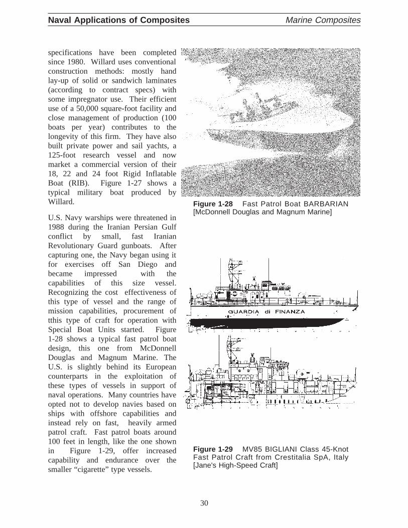
U.S. Navy warships were threatened in1988 during the Iranian Persian Gulfconflict by small, fast IranianRevolutionary Guard gunboats. Aftercapturing one, the Navy began using itfor exercises off San Diego andbecame impressed with thecapabilities of this size vessel.Recognizing the cost effectiveness ofthis type of vessel and the range ofmission capabilities, procurement oftthis type of craft for operation withSpecial Boat Units started. Figure1-28 shows a typical fast patrol boatdesign, this one from McDonnellDouglas and Magnum Marine. TheU.S. is slightly behind its Europeancounterparts in the exploitation ofthese types of vessels in support ofnaval operations. Many countries haveopted not to develop navies based onships with offshore capabilities andinstead rely on fast, heavily armedpatrol craft. Fast patrol boats around100 feet in length, like the one shownin Figure 1-29, offer increasedcapability and endurance over thesmaller “cigarette” type vessels.
30
Naval Applications of Composites Marine Composites
Figure 1-28 Fast Patrol Boat BARBARIAN[McDonnell Douglas and Magnum Marine]
Figure 1-29 MV85 BIGLIANI Class 45-KnotFast Patrol Craft from Crestitalia SpA, Italy[Jane's High-Speed Craft]

The U.S. recently conducted a design competition for the Mark V Special Operations Craft tosupport SEAL operations. Halter Marine offered a composite boat with surface piercingpropellers and an aluminum boat with waterjet propulsion. Peterson Builders built an aluminumcatamaran. The aluminum waterjet boat was chosen after testing in the Gulf of Mexico by theSpecial Warfare group at McDill Air Force Base in Tampa, FL. The operational assessmentprobably did not consider hull construction material as much as performance, although someconcern was noted regarding future repair of the composite hull. This is interesting to note, asmost of the boats used by Special Operations forces are of GRP construction. Table 1-3 is aninternational overview of composite military high-speed craft.
Table 1-3 Composite Military High-Speed Craft Overview
Country Yard Length Speed Construction
Denmark Danyard AalborgA/S 54 m 30 knots GRP sandwich
Italy
Cantieri NavaliItalcraft 22 m 52 knots GRP
Crestitalia SpA 27 m 45 knots GRP
Intermarine SpA23 m 40 knots GRP
27 m 40 knots GRP
Spain Polyships S.A. 17 m 67 knots Kevlar®, carbon,glass, polyester
Sweden
Smuggler MarineAB 25m 55 knots sandwich GRP
SwedeshipComposite AB 13.5 m 72 knots
Kevlar®, R-Glass,carbon fiberprepreg
Thailand TechnauticIntertrading Co. 26 m 27 knots GRP sandwich
with Airex core
United Kingdom
Ailsa-PerthShipbuilders 25 m 39 knots GRP
Colvic Craft Plc. 16 m 35 knots GRP
Paragon MannShipyard 50 ft 55 knots
Kevlar®, R-Glass,carbon fibermonocoque
VosperThornycroft (UK) 30 m 28 knots
GRP hull andaluminumsuperstructure
United States
Boston Whaler 25 ft 40 knot foam filled GRP
Fountain PowerBoats 42 ft 60 knots GRP
McDonnellDouglas/MagnumMarine
40 ft 48 knots Kevlar®/GRP
Tempest Marine 43.5 ft 50 knots GRP
Uniflite 36 ft 32 knots Kevlar®/GRP
31
Chapter One APPLICATIONS

Mine Counter Measure VesselsThe U.S. Navy in FY 1984 had contracted with Bell Aerospace Textron (now Textron Marine)to design and construct the first of 14 minesweeper hunters (MSH). The hulls were GRPmonohulls utilizing surface effect ship technology. Tests showed that the design could notwithstand explosive charges and subsequent redesign efforts failed.
In 1986, a contract was issued to Intermarine USA to study possible adaptations of theLerici classcraft to carry U.S. systems. TheLerici is 167 feet (50 meters) and is made with heavy single skinconstruction that varies from one to nine inches and uses no frames. Intermarine, USA ofSavannah, GA and Avondale Shipyards of New Orleans, LA were selected to build this class forthe U.S. Navy. Current plans call for a total of twelve Osprey class minehunters to be built (8 atIntermarine, 4 at Avondale). [1-31]
Both structural and manufacturing aspects of the Italian design were studied extensively by theU.S. Navy. Numerous changes to theLerici design took place to allow for U.S. Navy combatsystems; damage and intact stability; and shock and noise requirements. [1-32] Table 1-4 listssome of the characteristics of theOspreyclass minehunter. [1-33]
Table 1-4 Characteristics of the U.S. Navy Osprey Class Minehunter
Length: 57.2 meters (187 feet, 10 inches)
Beam: 11.0 meters (35 feet, 11 inches)
Draft: 2.9 meters (9 feet, 4 inches)
Displacement: 895 metric tons
Propulsion: two 800 hp amagnetic diesel engines with variablefluid drives turning two cycloidal propellers
Accommodations: 5 officers; 4 CPO; 42 enlisted
Construction ParticularsAll glass reinforcement for primary structure is E glass. Spun woven roving of 1400 grams per square meter isused for the hull, transverse bulkheads, and decks. The spun woven roving is a fabric with the weft directionreinforcement consisting of rovings that have been “tufted.” This treatment, which gives the fabric a fuzzyappearance, improves the interlaminar shear strength over traditional woven rovings. The superstructure isconstructed of a “Rovimat” material consisting of a chopped strand mat stitched to a woven roving. Stitching ofthe two fabrics was chosen to improve performance with the semi-automated resin impregnator (which is usedduring the lamination process). The total weight of the Rovimat is 1200 grams per square meter (400 g/m2 mat+ 800 g/m2 woven roving).
The resin is a high grade toughened isophthalicmarine polyester resin. It is speciallyformulated for toughness under shock loadsand to meet the necessary fabricationrequirements. The resin does not have brittlefracture characteristics of normal polyesterresins, which gives it excellent performanceunder underwater explosive loads. Combinedwith spun woven roving, the laminate providessuperior shock and impact resistance. Theresin formulation has been optimized forimproved producibility. Significant is the longgel time (up to four hours) with low exothermand a long extended delay time to produce aprimary bond. [1-32]
32
Naval Applications of Composites Marine Composites

The Swedish and Italian Navies have been building minesweeping operations (MSO) shipswith composite technology for many years. The Swedish Navy, in conjunction with the RoyalAustralian Navy and the U.S. Navy, studied shock loadings during the development of theSwedish composite MSO. Shock loadings (mine explosion simulations) were performed onpanels to study candidate FRP materials and configurations such as:
• Shapes and different height/width ratio of frames;
• Epoxy frames;
• Sprayed-up laminates;
• Corrugated laminates;
• Sandwich with different core densities and thicknesses;
• Different types of repairs;
• Weight brackets and penetrations on panels;
• Adhesion of fire protection coatings in shock;
• The effect of double curved surfaces; and
• Reduced scale panel with bolted and unbolted frames.
This extensive testing program demonstrated that a frameless Glass Reinforced Plastic (GRP)sandwich design utilizing a rigid PVC foam core material was superior in shock loading andresulted in better craft and crew survivability. The Swedish shock testing program demonstratesthat when properly designed, composite materials can withstand and dampen large shock loads.[1-34] Table 1-5 summarizes the current use of FRP for mine counter measure vessels.Althoughdesign and performance issues associated with sandwich construction for minehuntershave beendemonstrated, most recent new orders for minehunters worldwide are for thick-sectioned,single-skin construction.
Swiftships of Morgan City,LA is primarily a yard thatbuilds in aluminum and steel.A contract with the EgyptianNavy created the opportunityfor this yard to get involvedwith composite construction.Three of these 100-footvessels, shown at right, havebeen delivered. Swiftship'sProgram Engineer largelycredits the resources andresearch work of the U.S.Navy with making thetransition to compositeconstruction possible for thismedium-sized yard.
33
Chapter One APPLICATIONS
Figure 1-30 Profile and Equipment Layout of the Swift-ships 33.5m CMH [June, 94, WARSHIP TECH]

Table 1-5 shows the evolution of some key classes of mine counter measure vessels that havebeen developed in Europe since 1960. In the 1960s, the United Kingdom built theHMSWilton, the first GRP minesweeper. These ships were commissioned in 1973, closely followedby the Hunt Class. Both these vessels used isophthalic resin with up to 47 layers of wovenroving in the hull. TheTripartite Class minehunter was jointly developed by France, Belguimand the Netherlands [1-35]. Intermarine's venerableLerici class has undergone numerousmodifications to suit the needs of various countries, including the United States and mostrecently Austrailia.
Table 1-5 Current FRP Mine Counter Measure Vessels [1-23, 1-31]
Typ
eof
Con
stru
ctio
n
Class Country Builder
Built
(1995)
Total
∆(tons)
LOA
(m)
Speed
(kts)S
tiffe
ned
Sin
gle
Ski
n
Wilton United Kingdom
VosperThornycroft
1 1 425 46 15
Hunt United Kingdom 13 13 625 60 17
Sandown United Kingdom 5 9 378 52.5 14
Sandown Saudi Arabia 3 3 378 52.5 14
Mod. Sandown Spain Bazan 0 8 530 54 15
Aster Belgium Beliard 7 7 544 51.5 15
Eridan FranceLorient Dockyard
9 10 544 49.1 15
Munsif Pakistan 2 3 535 51.6 15
Alkmaar NetherlandsVan derGiessen-de Norde
15 15 588 51.5 15
Mod. Alkmaar Indonesia 2 2 588 51.5 15
Kiskii Finland Oy Fiskars AB 7 7 20 15.2 11
Foa
mS
andw
ich Landsort Sweden Karlskronavarvet 8 8 360 47.5 15
Landsort Singapore Karlskronavarvet 2 4 360 47.5 15
YSB Sweden Karlskronavarvet 0 4 175 36 12+
Bay Austrailia Carrington 2 2 170 30.9 10
Stan Flex 300 Denmark Danyard Aalborg A/S 8 14 300 54.0 30+
Uns
tiffe
ned,
Thi
ckS
kin
Lerici Italy
Intermarine, SpA
4 4 520 50 15
Gaeta Italy 6 6 720 52.5 15
Lerici Nigeria 2 2 540 51 15.5
Kimabalu Malaysia 4 4 540 51 16
Modified Lerici South Korea Kang Nam 6 12 540 51 15.5
Gaeta Austrailia Newcastle 0 6 720 52.5 15
Osprey United States Intermarine, USA/Avondale 3 12 660 57.3 12
34
Naval Applications of Composites Marine Composites

ComponentsComposite ship stacks are also under investigation for the U.S. surface fleet. Non-structural shipcomponents are being considered as candidates for replacement with composite parts. Two typesof advanced non-structural bulkheads are in service in U.S. Navy ships. One of these consists ofaluminum honeycomb with aluminum face sheets, and the other consists of E-glass FRP skinsover an aramid core material. [1-1]
The Naval Surface Warfare Center, Carderock contracted for the construction of a shipboardcomposite foundation. An open design competition attracted proposals featuring hand lay-up,resin transfer molding, pultrusion and filament winding. A filament wound prototype proposedby Brunswick Defense was selected, in part, because the long term production aspects of themanufacturing process seemed favorable. The foundation has successfully passed a shock test.
Development of composite propulsion shafts for naval vessels is being investigated to replacethe massive steel shafts that comprise up to 2% of the ship's total weight. Composite shafts ofglass and carbon reinforcing fibers in an epoxy matrix are projected to weigh 75% less than thetraditional steel shafts and offer the advantages of corrosion resistance, low bearing loads,reduced magnetic signature, higher fatigue resistance, greater flexibility, excellent vibrationdamping and improved life-cycle cost. [1-1]
The U.S. Navy studied the benefits of hydrofoils in 1966. The USN experimental patrol crafthydrofoil (PCH-1) Highpoint was evaluated for weight savings. The overall weight savingsover HY 80 steel were 44% for glass reinforced plastic, 36% for titanium alloy and 24% forHY 130 steel. In the mid 1970s a hydrofoil control flap (Figure 1-31) and a hydrofoil boxbeam element applying advanced graphite-epoxy composites were evaluated by the Navy. [1-9]
35
Chapter One APPLICATIONS
Figure 1-31 U.S. Navy Patrol Craft Hydrofoil (PCH-1) Composite Flap [ASM Engi-neer's Guide to Composite Materials]

Table 1-6 Recent Navy Composite Machinery Application Projects[George Wilhelmi, Code 823, NSWC, Annapolis]
Program Objective Status
Standard Family ofCentrifugal Pumps
“Affordability” through Navy-ownedstandardized design; max.interchangeable pumpcomponents; and improvedperformance & reliability withcomposite wetted parts
Prototype manufacturing hasstarted under design contractawarded to IDP in March 1992
Glass-Reinforced Plastic(GRP) Piping Systems
Develop tech. base & designguidance for max. utilization ofMIL-P-24608A GRP pipingmaterial in non-vital systems to200 psig at 150°F; to reducelife-cycle costs associated withcorrosion/erosion of Cu-Ni andsteel in seawater
Design practices manual/uniform-industrial processinstruction & shock guidancecompleted; optimization of fireprotective insulation underway
Composite Ball Valves
Develop low-maintenance,affordable composite ball and flowcontrol valves suitable for 200psig/150°F service in metallic andnonmetallic piping systems
Lab evaluation of commercialvalve complete; ship evaluationunderway; marinization strategiesdeveloped
Composite VentilationDucting
Develop corrosion-free,fire-resistant, light weight ductingto replace galvanized steel andaluminum in air supply andexhaust applications sufferingaccelerated corrosion damage
1st surface ship application aboardCVN71 in Feb 93 and trialinstallation on CG-47 class inFY95. GLCC now optimizingprocess and fire hardening
Composite ResilientMachinery Mounts
Develop lightweight,corrosion-free, shock-ratedcomposite version of standardEES-type resilient machinery
Composite prototype mountspassed hi-impact shockrequirements, impact shockrequirements; (6.2) nearcompletion; requires extensionover light and medium load weightrange
Composite Diesel Engine
Develop lightweight, low-magneticsignature marine diesel engineemploying metal, polymer, andceramic matrix compositematerials
ONR, GLCC and private Americandiesel manufacturers have teamedto accelerate 6.2 R & D
Composite PropulsionShafting
Develop lightweight,corrosion-free, propulsion shaftingwith tailorable properties foracoustic and magnetic silencingbenefits
Full-diam, short length, 50,000 HPAOE composite section evaluatedin lab test fixture with encouragingresults
Composite Nuts & Bolts;Ladders; Grates; ScreensPump Impellers; etc.
Exploit composites developed forU.S. chemical processing industryto solve chronic corrosionproblems with steel and Cu-Ni insewage tank and flight deckapplications
Most shipboard installations areproving successful following 2 to 5years of onboard experience
36
Naval Applications of Composites Marine Composites

Conventional heat exchangers usecopper alloy tubes to transportseawater as a cooling medium.The copper-nickel tubes havehigh heat transfer rates, but theyare subject to corrosion, erosionand fouling. The deterioratingtubes force operators to run theequipment at reduced flow rates,which in turn reduces the overalleffectiveness. Compositematerials offer the potential toeliminate corrosion and erosionproblems, as well as reduce theweight of heat exchangerassemblies. An ongoing study byJoseph Korczynski, Code 823,NSWC, Annapolis is looking atcandidate composite materialsthat were optimized to increasethermal conductivity, acharacteristic not usuallyassociated with these types ofmaterials. Figure 1-32 illustratesthe encouraging results of thisprogram.
Composite piping system fire survivability has also been evaluated using glass reinforced epoxyand vinyl ester piping systems with various joining methods and under dry, stagnant water, andflowing water conditions. The results of these tests have been compared with metallic alternatives.For example, 90-10 Cu-Ni Sil-brazed joints survive 2-3 minutes with dry pipe and less than 20minutes with stagnant water in the pipe. Epoxy pipe assemblies survived less than 3 minutes in afull-scale fire when pressurized to 200 psig stagnant water. The joints failed catastrophically.However, application of a promising fire barrier around the pipe joints improved survivability timeto 23 minutes, and a completely insulated assembly survived for 30 minutes with no leaks after thefire.
One of the most successful Navy composites machinery program to date involves thedevelopment of a standard family of composite centrifugal pumps. The pumps employ alimited number of housing sizes, impellers, and drives to cover a wide range of pressure andflow rate requirements. The pump housing can be fabricated from glass-reinforced epoxy,vinyl ester, or polyester. High velocity erosion investigations with various fiber reinforcedpolymer matrix composite pump materials showed excellent corrosion-erosion performance ofcomposites relative to gun metal bronze (widely used in marine centrifugal pumps) over avelocity range of 0 to 130 ft/sec. However, the composites did not fare as well undercavitation conditions, where they showed generally inferior performance to the bronze. Inmost marine pump applications, however, cavitation is not expected to be a problem. [1-30]
37
Chapter One APPLICATIONS
Figure 1-32 Ranking of Effectiveness (AllowableStress, Conductivity over Density) of Various Materi-als Considered for Heat Exchangers [Joseph Korc-zynski, Code 823, NSWC, Annapolis]
Thermoplastics Thermosets Metal Alloys
Rel
ativ
eE
ffect
iven
ess

Advanced Material Transporter (AMT)A recent Navy project that encompasses the total design and fabrication of a composite hullstructure is the Advanced Material Transporter (AMT), where a 0.35 scale model was built.
The material selected for the AMT was an E-glass woven roving fabric and vinyl ester resin.Seemann Composites lnc. was contracted to fabricate the entire ship hull and secondarystructures of the AMT model using the Vacuum Assisted Resin Transfer Molding (VARTM)process. A modular construction approach was used to fabricate large components of theAMT, which were later assembled using a combination of bolting and bonding. The fabricreinforcement for the primary hull was laid up dry for the full thickness of the hull, and theresin was injected in one stage in only three and a half hours. The hull was cured at roomtemperature overnight and then longitudinal hat-stiffeners were fabricated in-place onto theboat hull.
The 40-ft long cargo deck was fabricated using a 0.5-in. thick balsa core sandwichconstruction, and then room temperature cured overnight. Deep longitudinal hat-stiffenergirders were fabricated in-place onto the deck bottom, similar to the girders on the ship hull.The bulkheads and superstructure were built using the same general approach as the main deck.Some of the critical joints for the main deck and bulkheads to the hull were completed usingVARTM and other less critical connections were fabricated using hand lay-up. To reduce thetime required for post curing, the entire boat hull was fully assembled and then post cured at anelevated temperature of 120°F for eight hours. The estimated structural weight for the model is7000-lbs, which is 30% lighter than an aluminum hull concept. [1-36]
38
Naval Applications of Composites Marine Composites
Figure 1-33 Lay-up Configuration for AMTValidation Model [Nguyen, 93 Sml Boat]
Sandwich Wing Walls7.5 lb balsa
Sandwich Deck9.5 lb balsa
StiffenersPVC Foam Filled
HullSolid GRP
Figure 1-34 Profile of AMT Vali-dation Model [Nguyen, 93 SmlBoat]
Figure 1-35 Midships FEM ofAMT Validation Model [Nguyen, 93Sml Boat]

Deckhouse StructureThe U.S. Navy has made considerableprogress recently in the development anddemonstration of blast-resistant compositedesign concepts and prototypes fordeckhouses, superstructures and othertopside enclosures for naval combatants.These composite concepts offersignificant advantages over conventionalsteel structures, including a 35 to 45%reduction in weight, reduced corrosionand fatigue cracking, and improved firecontainment. [1-37]
A single-skin stiffened and a sandwichcore concept have been developed fortopside applications. The stiffenedconcept involves the assembly ofprefabricated hat-stiffened GRP panelsusing prefabricated GRP connectionangles and bolted/bonded joint details.Panel stiffeners are tapered to maximizepeel resistance, to minimize weight, andto simplify the joints and panelconnections. The sandwich conceptutilizes prefabricated sandwich panelsthat are attached through bolting andbonding to a supporting steel framework.A steel framework is attractive for theconstruction of composite topsidestructures since it is readily erected in ashipyard environment, allows for theattachment of prefabricated high-qualityGRP panels, and provides resistance tocollapse at elevated temperatures underpotential fire insult.
France's newest frigate makes use ofglass/balsa core panels made withpolyester resin for both deckhouse anddeck structure to reduce weight andimprove fire performance as compared toaluminum. The shaded areas of figure1-38 shows the extent of compositesandwich construction. [1-38]
39
Chapter One APPLICATIONS
Figure 1-36 Hat-Sti ffened DeckhousePanel Test Elements [Scott Bartlett, NSWC]
Lap Joint
Full-ScaleBeam/JointComponent Lap Joint
Material Characterization
Figure 1-37 Arrangement of GRP Deck-house Proposed for the SSTDP Sealift Ship[Scott Bartlett, NSWC]
Figure 1-39 French LA FAYETTE ClassFrigate Showing Area Built with Balsa-CoredComposites [DCN Lorient, France]

Advanced Hybrid Composite MastThe Advanced Enclosed Mast/Sensor (AEM/S)project represents a chance for the U.S. Navy toevaluate the first large-scale composite componentinstalled onboard a surface combatant. The sandwichstructure is designed to support and protect an arrayof sensors typically found mounted on metallic mastserected using truss elements. The AEM/S has fullyintegrated sensor technology, electromagnetics, andsignature reduction made possible by the engineeringlatitude of today’s composite materials. Extensivematerial and structural testing preceded thefabrication of the mast at Ingalls Shipyard inPascagoula, MS. The Advanced EnclosedMast/Sensor (AEM/S) is an 87-foot high, hexagonal
structure that measure 35 feet across.The 40-long ton structure wasfabricated in two halves using theSCRIMP process. Conventionalmarine composite materials, such asE-glass, vinyl ester resin and balsa andfoam cores are utilized throughout thestructure. Because mechanical jointswere engineered into both the middleand the base of the structure, a lot ofanalytical and testing focused onbolted composite joints.
GLCC ProjectsThe GLCC has collaborated with the Navy on anumber of surface ship applications ofcomposite mateials, including ventilationducting, electronics enclosures, topside structureand a replacement rudder for the MCMminehunter class. The composite MCM rudderis 50% of the weight for a metallic counterpartat a simialr cost, with anticipated reducedcorrosion-related life-cycle costs. Aclosed-mold resin infusion process (RIRM) wasvalidated for massive ship structural parts.
40
Naval Applications of Composites Marine Composites
Figure 1-40 Advanced Enclosed Mast/Sensor(AEM/S) at Stepping Ceremony on the USSRadford DD 968 [NSWC, Carderock]
Figure 1-39 Configuration ofthe Advanced EnclosedMast/Sensor [NSWC, Carderock]
Figure 1-41 The MCM CompositeRudder RIRM process [StructuralComposites]