c earthquake engineering
DESCRIPTION
C Earthquake EngineeringTRANSCRIPT
1
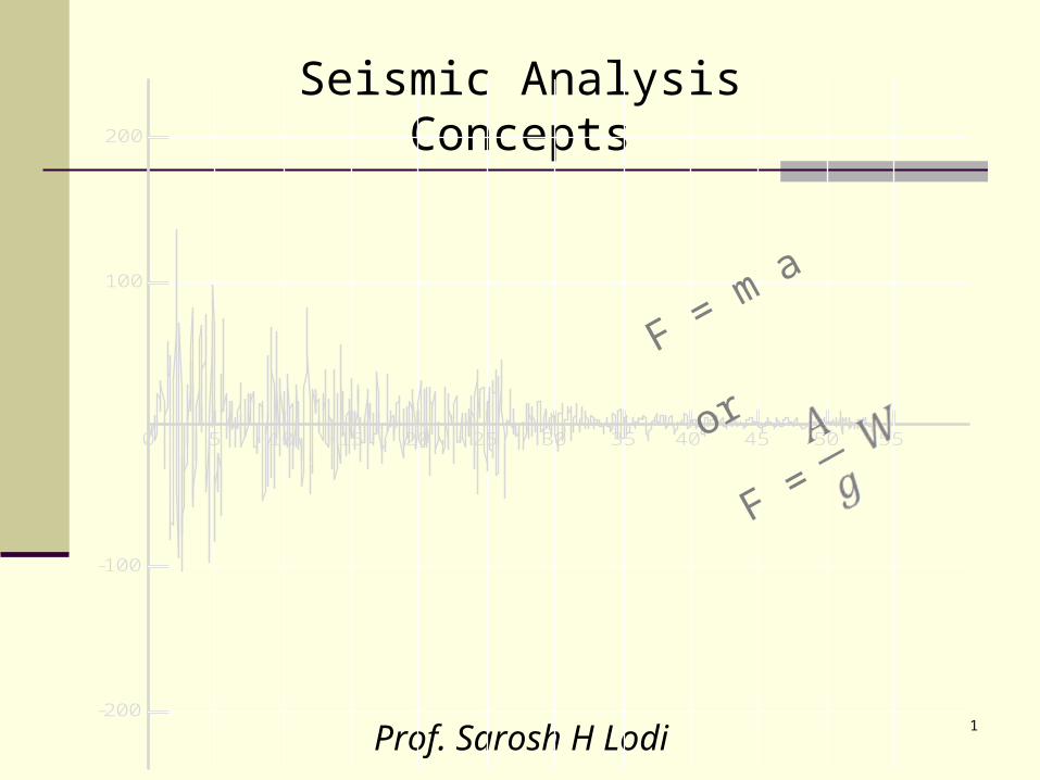
Seismic Analysis Concepts
Prof. Sarosh H Lodi
0 5 10 15 20 25 30 35 40 45 50 55
-100
-200
100
200
F = m a
or
F =
2
Acceleration vs Time, File ELCENTRO
Time (SECONDS)
0 5 10 15 20 25 30 35 40 45 50 55
-100
-200
100
200
Tra
nsla
tio
n A
cce
lera
tio
n (
INC
HE
S/S
EC
ON
DS
^2
)
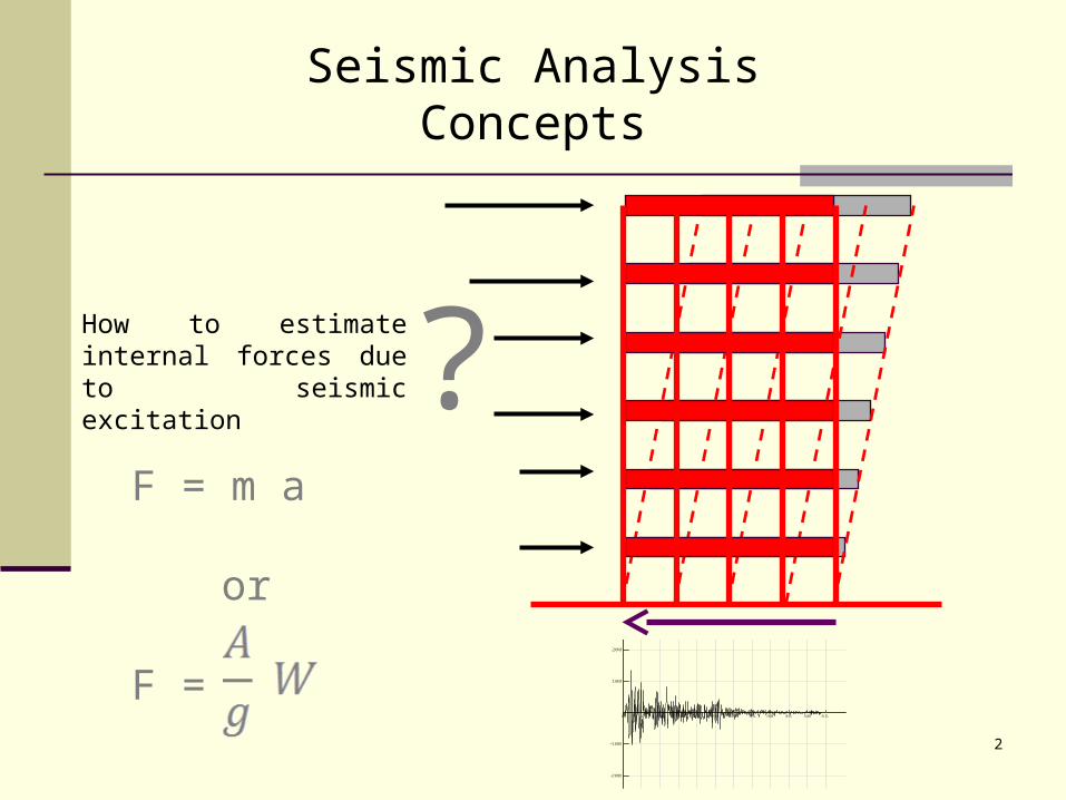
?How to estimate internal forces due to seismic excitation
F = m a
or
F =
Seismic Analysis Concepts
3
Earthquake Protective Design Philosophical Issues
High probability of “Failure”
“Failure” redefined to permit behavior (yielding) that would be considered failure under other loads.
High Uncertainty Importance of
Details
“In dealing with earthquakes we must contend with appreciable probabilities that failure will occur in the near future. Otherwise, all the wealth of the world would prove insufficient… We must also face uncertainty on a large scale… In a way, earthquake engineering is a cartoon… Earthquakes systematically bring out the mistakes made in design and construction, even the minutest mistakes.” Newmark & Rosenblueth
4
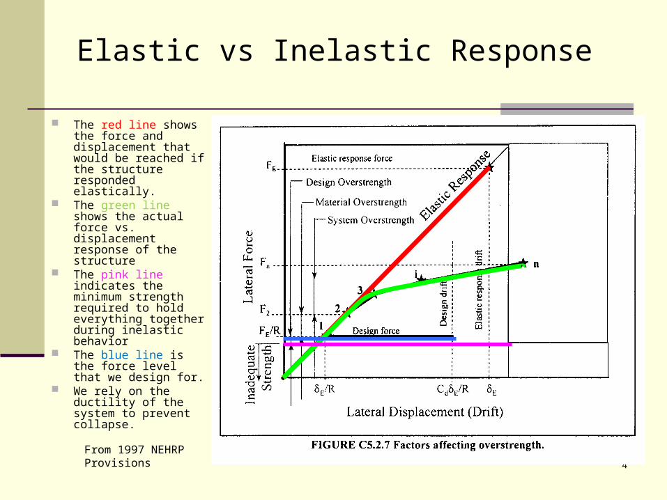
Elastic vs Inelastic Response
The red line shows the force and displacement that would be reached if the structure responded elastically.
The green line shows the actual force vs. displacement response of the structure
The pink line indicates the minimum strength required to hold everything together during inelastic behavior
The blue line is the force level that we design for.
We rely on the ductility of the system to prevent collapse.
From 1997 NEHRP Provisions
5
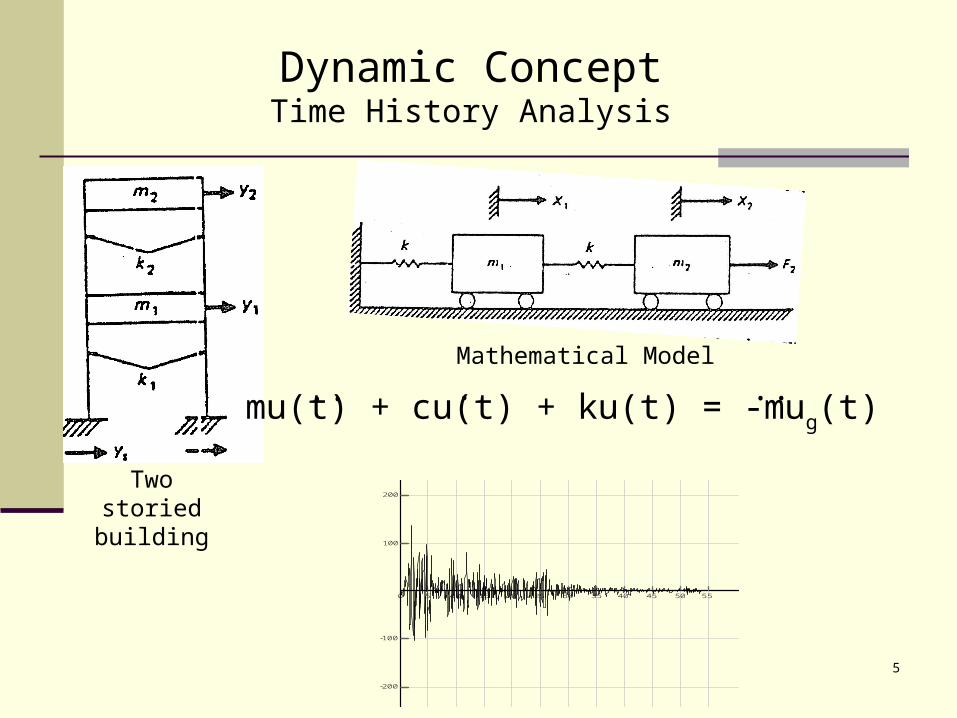
Dynamic ConceptTime History Analysis
Mathematical Model
Two storied building
mu(t) + cu(t) + ku(t) = -mug(t).. . ..
Acceleration vs Time, File ELCENTRO
Time (SECONDS)
0 5 10 15 20 25 30 35 40 45 50 55
-100
-200
100
200
Tra
nsla
tio
n A
cce
lera
tio
n (
INC
HE
S/S
EC
ON
DS
^2
)
6
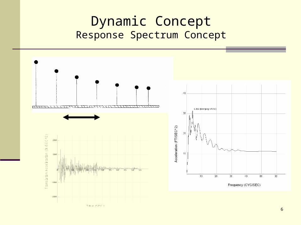
Acceleration vs Time, File ELCENTRO
Time (SEC)
0 5 10 15 20 25 30 35 40 45 50 55
-100
-200
100
200
Tra
nsla
tion A
ccele
ration (
IN/S
EC
^2)
Dynamic ConceptResponse Spectrum Concept
7
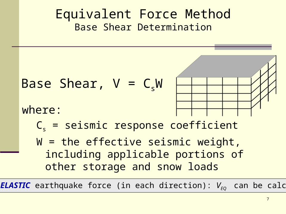
where:Cs = seismic response coefficient
W = the effective seismic weight, including applicable portions of other storage and snow loads
Base Shear, V = CsW
Total ELASTIC earthquake force (in each direction): VEQ can be calculated
Equivalent Force MethodBase Shear Determination
8
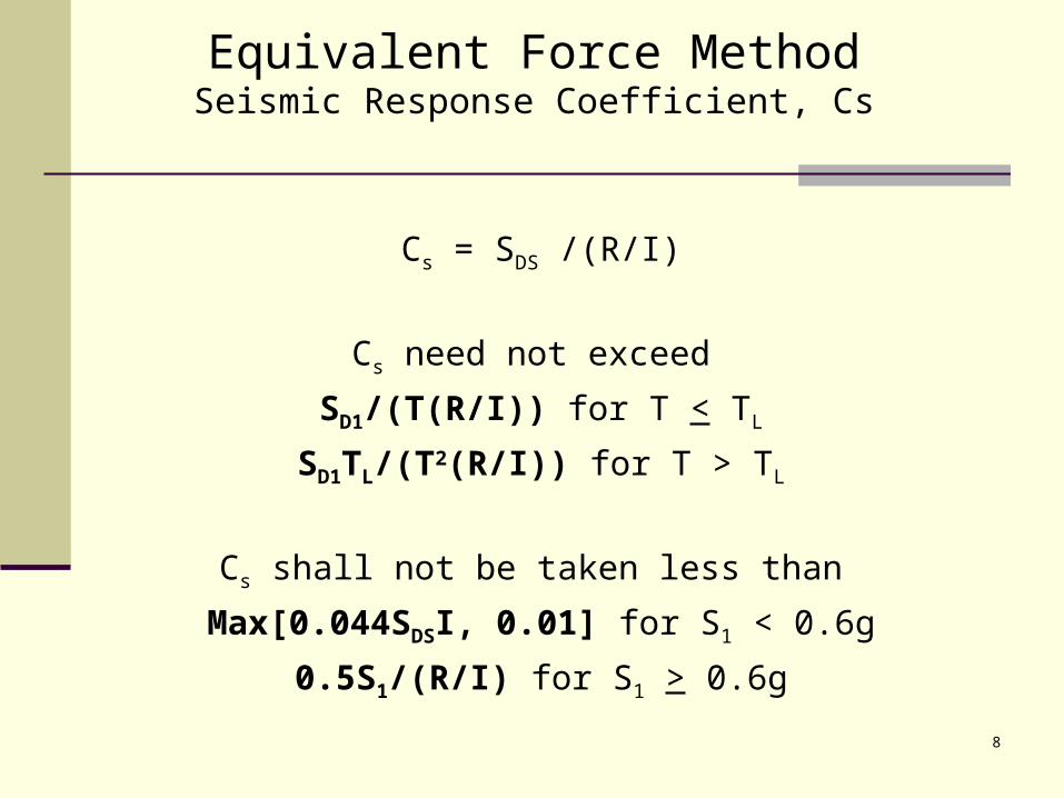
Equivalent Force MethodSeismic Response Coefficient, Cs
Cs = SDS /(R/I)
Cs need not exceed
SD1/(T(R/I)) for T < TL
SD1TL/(T2(R/I)) for T > TL
Cs shall not be taken less than
Max[0.044SDSI, 0.01] for S1 < 0.6g
0.5S1/(R/I) for S1 > 0.6g
9
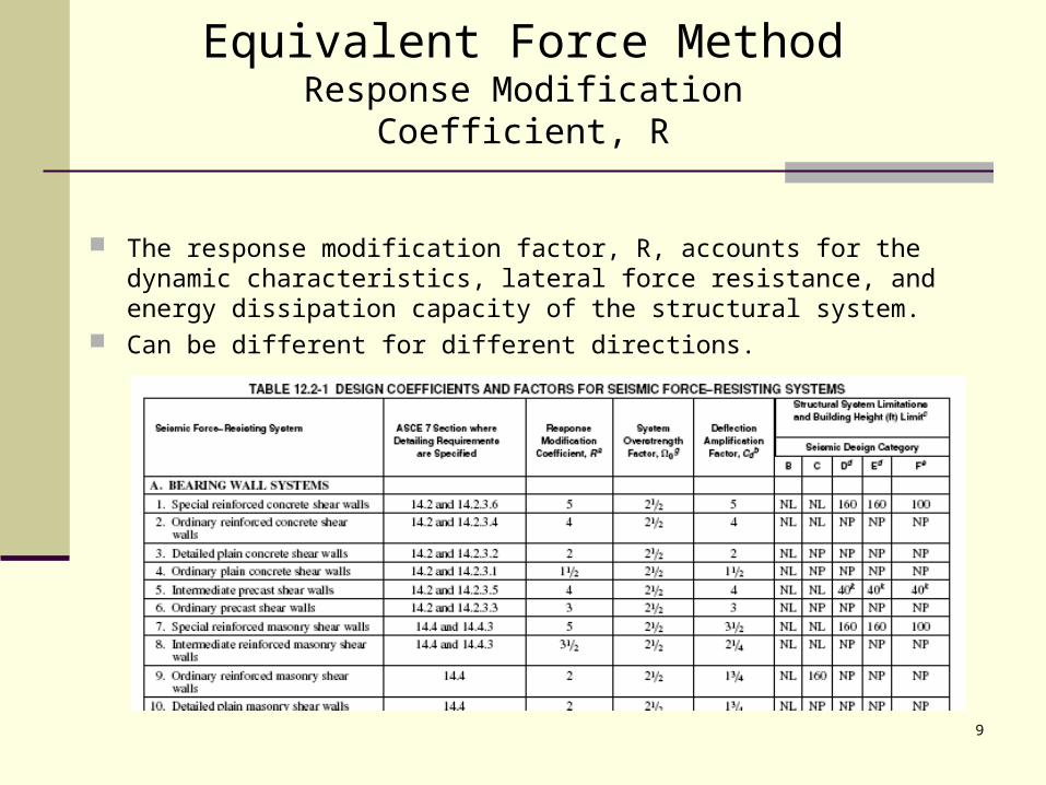
Equivalent Force MethodResponse Modification Coefficient, R
The response modification factor, R, accounts for the dynamic characteristics, lateral force resistance, and energy dissipation capacity of the structural system.
Can be different for different directions.
10
Equivalent Force MethodFundamental Period, T
May be computed by analytical means May be computed by approximate means, Ta
Where analysis is used to compute T:
T < Cu Ta
May also use Ta in place of actual T
10ASCE 7-05 Seismic Provisions - A Beginner's Guide to ASCE 7-05
11
Equivalent Force MethodApproximate Fundamental Period, Ta
An approximate means may be used.
Ta = CThnx
Where:
CT = Building period coefficient.
hn = height above the base to the highest level of the building
for moment frames not exceeding 12 stories and having a minimum story height of 10 ft, Ta may be taken as 0.1N, where N = number of stories.
For masonry or concrete shear wall buildings use eq 12.8-9 Ta may be different in each direction.
12
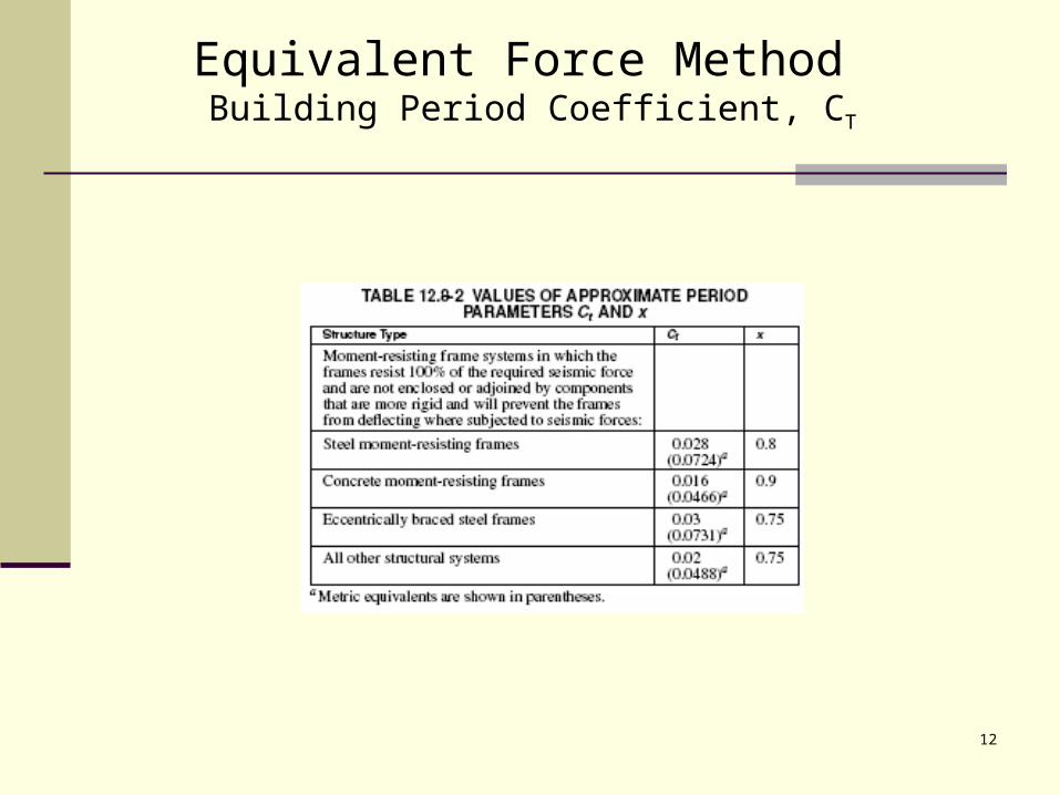
Equivalent Force Method Building Period Coefficient, CT
13
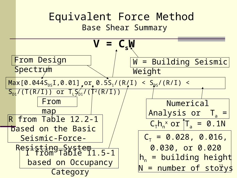
Equivalent Force Method Base Shear Summary
V = CsW
W = Building Seismic Weight
Max[0.044SDSI,0.01] or 0.5S1/(R/I) < SDS/(R/I) < SD1/(T(R/I)) or TLSD1/(T2(R/I))
From Design Spectrum
From map
R from Table 12.2-1 based on the Basic Seismic-Force-
Resisting System
Numerical Analysis or Ta = CThn
x or Ta = 0.1N
CT = 0.028, 0.016, 0.030, or 0.020
hn = building heightN = number of storys
I from Table 11.5-1 based on Occupancy Category
14
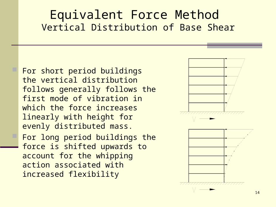
Equivalent Force Method Vertical Distribution of Base Shear
For short period buildings the vertical distribution follows generally follows the first mode of vibration in which the force increases linearly with height for evenly distributed mass.
For long period buildings the force is shifted upwards to account for the whipping action associated with increased flexibility
15
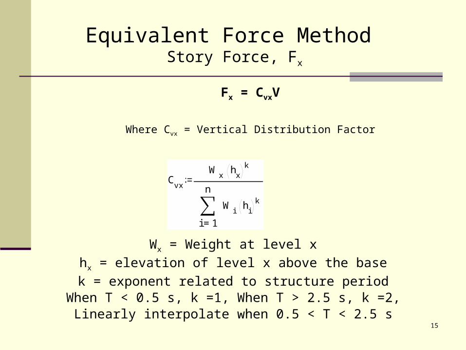
Equivalent Force Method Story Force, Fx
Fx = CvxV
Where Cvx = Vertical Distribution Factor
Wx = Weight at level x
hx = elevation of level x above the base
k = exponent related to structure period When T < 0.5 s, k =1, When T > 2.5 s, k =2,
Linearly interpolate when 0.5 < T < 2.5 s
Cvx
Wx
hx
k
1
n
i
Wi
hi
k
=
16
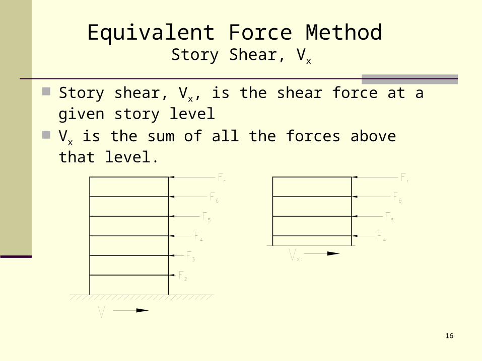
Equivalent Force Method Story Shear, Vx
Story shear, Vx, is the shear force at a given story level
Vx is the sum of all the forces above that level.
17
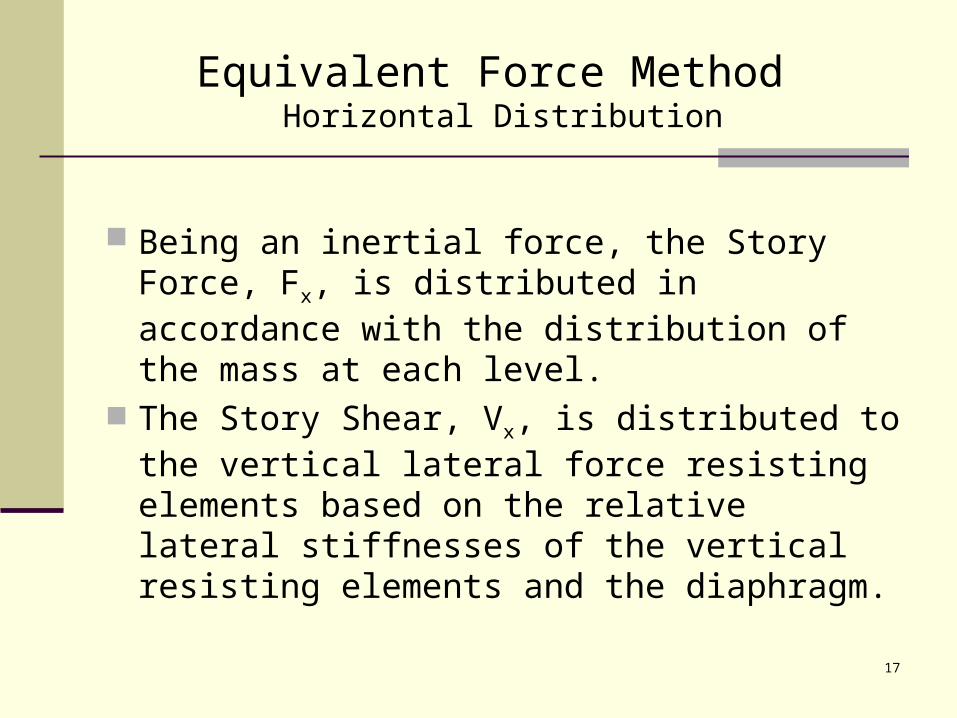
Equivalent Force Method Horizontal Distribution
Being an inertial force, the Story Force, Fx, is distributed in accordance with the distribution of the mass at each level.
The Story Shear, Vx, is distributed to the vertical lateral force resisting elements based on the relative lateral stiffnesses of the vertical resisting elements and the diaphragm.
18
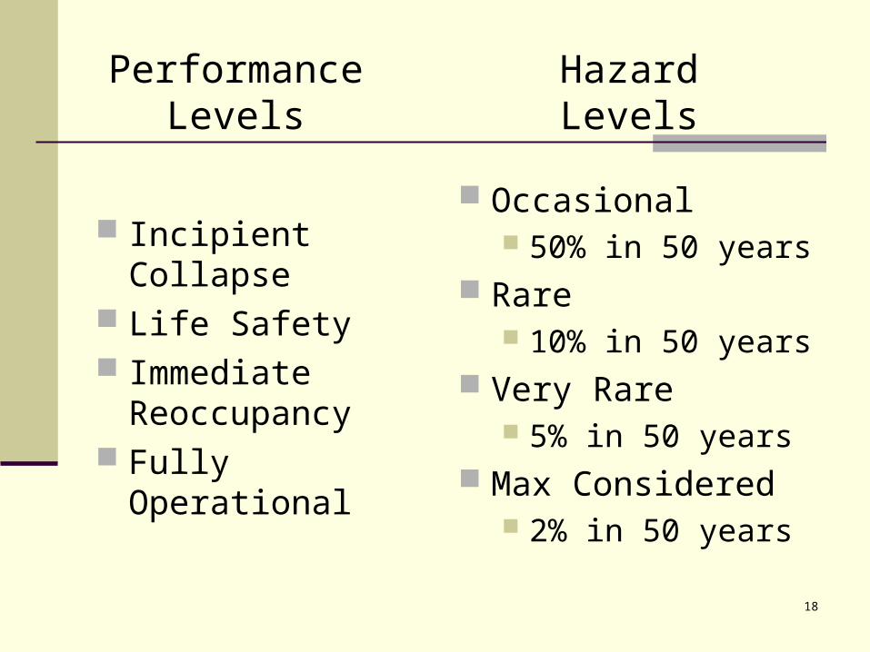
Hazard Levels
Incipient Collapse Life Safety Immediate
Reoccupancy Fully Operational
Occasional 50% in 50 years
Rare 10% in 50 years
Very Rare 5% in 50 years
Max Considered 2% in 50 years
Performance Levels
19
Design Objective Defined
A specific performance level given a specific earthquake hazard level
Stated basis of current codes: Life safety (+some damage control) at 10% in
50 year event (nominally)
20
Development of Performance-based Seismic Design Standards and Criteria
21
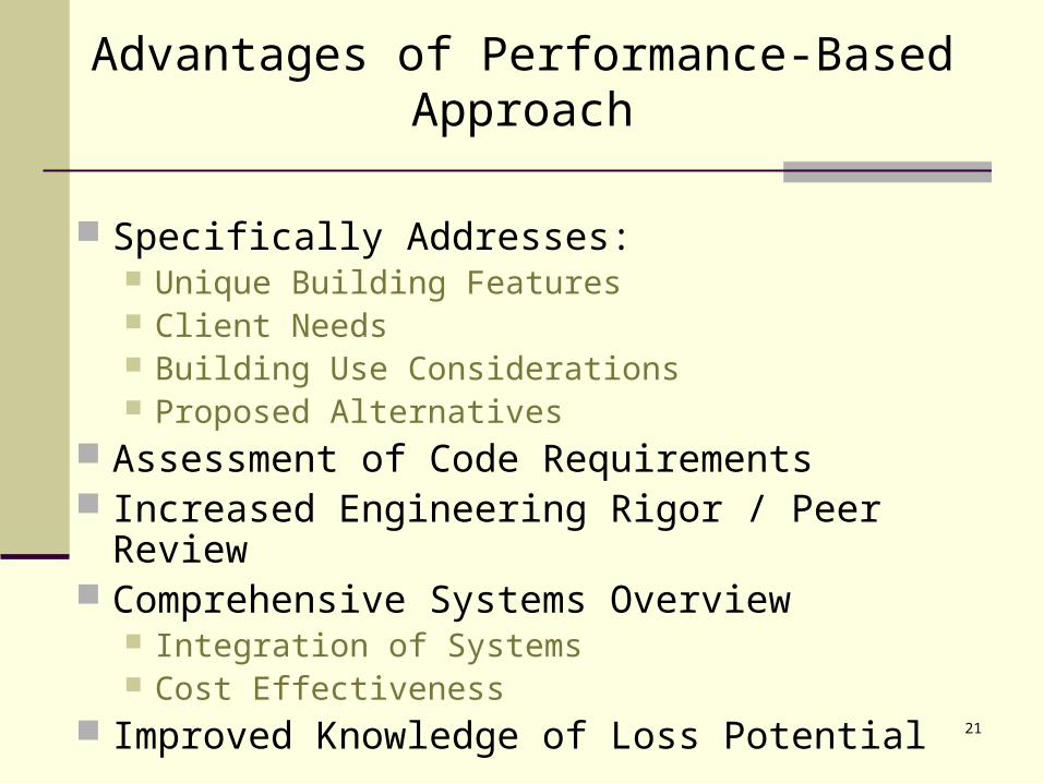
Advantages of Performance-Based Approach
Specifically Addresses: Unique Building Features Client Needs Building Use Considerations Proposed Alternatives
Assessment of Code Requirements Increased Engineering Rigor / Peer Review Comprehensive Systems Overview
Integration of Systems Cost Effectiveness
Improved Knowledge of Loss Potential
22
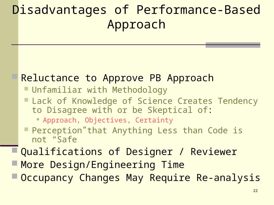
Disadvantages of Performance-Based Approach
Reluctance to Approve PB Approach Unfamiliar with Methodology Lack of Knowledge of Science Creates Tendency to
Disagree with or be Skeptical of: Approach, Objectives, Certainty
Perception that Anything Less than Code is not “Safe” Qualifications of Designer / Reviewer More Design/Engineering Time Occupancy Changes May Require Re-analysis
23
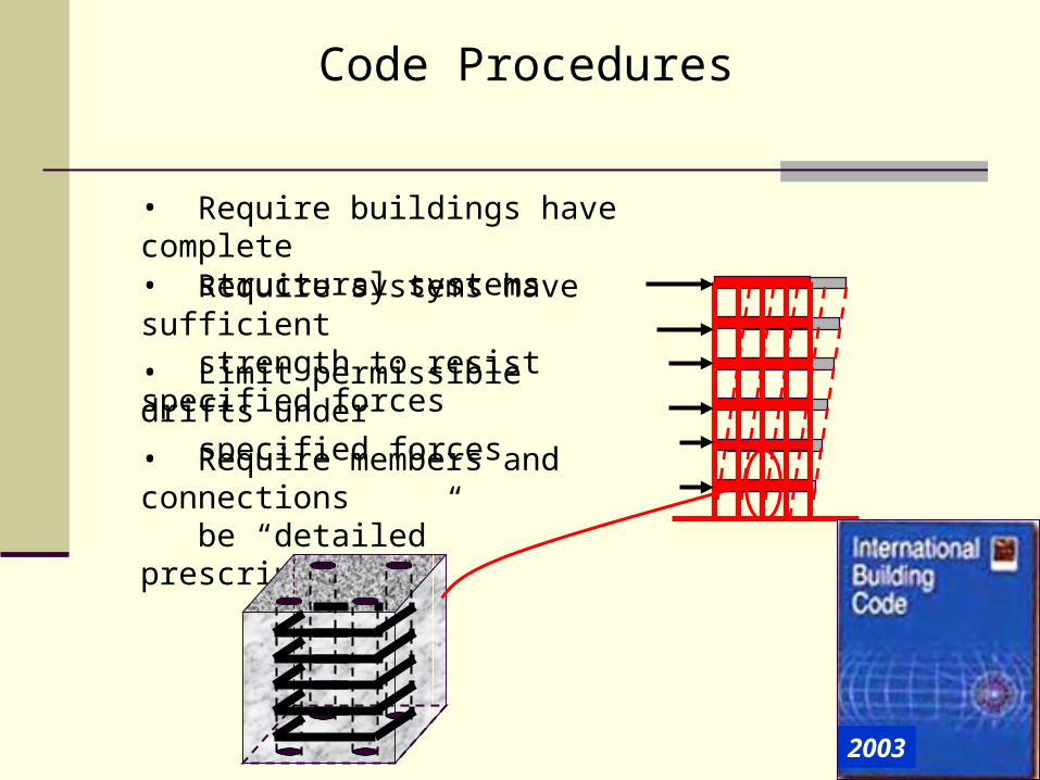
• Limit permissible drifts under specified forces
• Require buildings have complete structural systems
Code Procedures
• Require systems have sufficient strength to resist specified forces
• Require members and connections be “detailed” prescriptively
2003
24
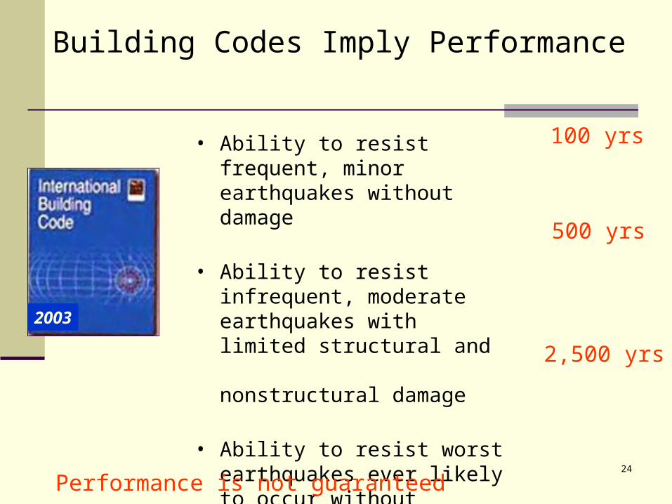
Building Codes Imply Performance
• Ability to resist frequent, minor earthquakes without damage
• Ability to resist infrequent, moderate earthquakes with limited structural and nonstructural damage
• Ability to resist worst earthquakes ever likely to occur without collapse or major life safety endangerment
100 yrs
500 yrs
2,500 yrs
Performance is not guaranteed
2003
25
Building Codes & Performance Warranties
• If a building is affected by an extreme event and performs poorly:– There is an expectation of how the building
should have performed but no implied warranty• The only warranty is that the engineer complied
with the standard of care– For most buildings, demonstration that a design
was performed in accordance with the building code will provide adequate proof of conformance to the standard of care
26
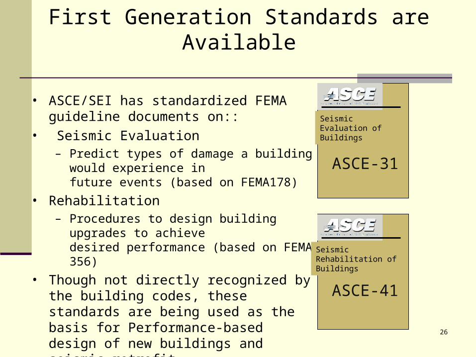
First Generation Standards are Available
• ASCE/SEI has standardized FEMA guideline documents on::
• Seismic Evaluation– Predict types of damage a building would
experience in future events (based on FEMA178)
• Rehabilitation– Procedures to design building upgrades to
achievedesired performance (based on FEMA 356)
• Though not directly recognized by the building codes, these standards are being used as the basis for Performance-based design of new buildings and seismic retrofit
SeismicEvaluation ofBuildings
ASCE-31
SeismicRehabilitation ofBuildings
ASCE-41
27
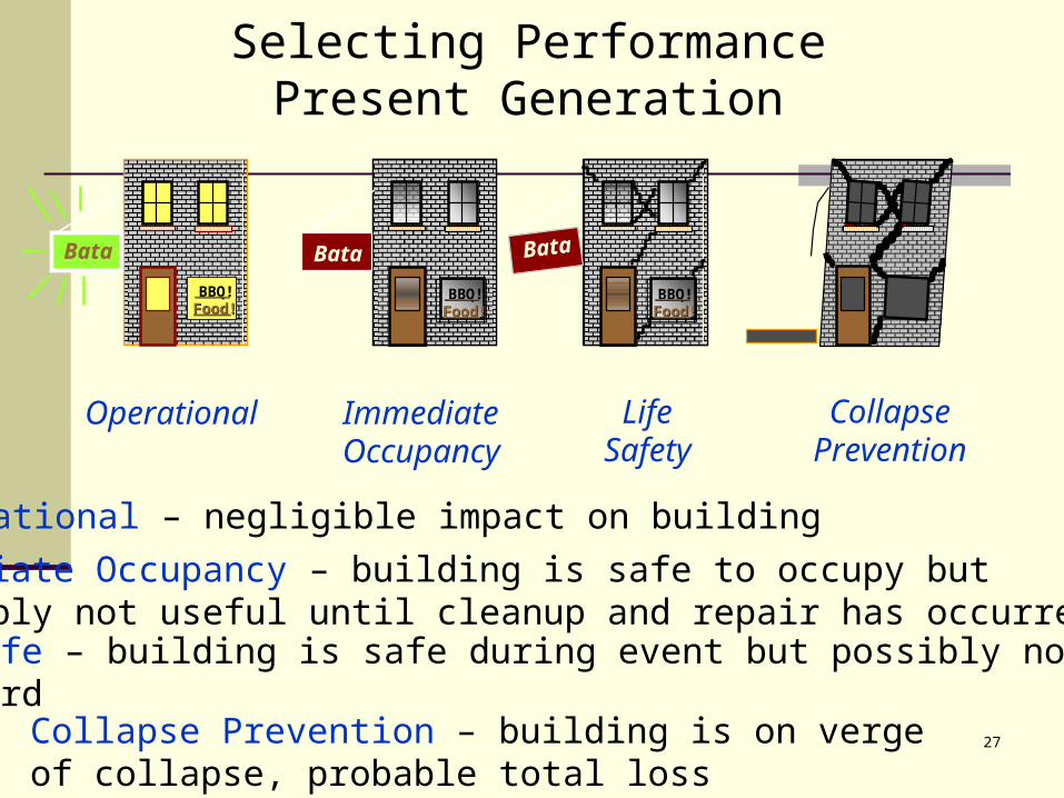
Selecting PerformancePresent Generation
Bata
BBQ!Food!Food!
Operational
Operational – negligible impact on building
Beer!Beer!Food!Food!
Joe’s
Beer!Beer!Food!Food!BBQ!Food!Food!
Joe’sBata
ImmediateOccupancy
Immediate Occupancy – building is safe to occupy butpossibly not useful until cleanup and repair has occurred
Beer!Beer!Food!Food!
Joe’s
Beer!Beer!Food!Food!BBQ!Food!Food!
Bata
LifeSafety
Life Safe – building is safe during event but possibly notafterward
CollapsePrevention
Collapse Prevention – building is on verge of collapse, probable total loss
28
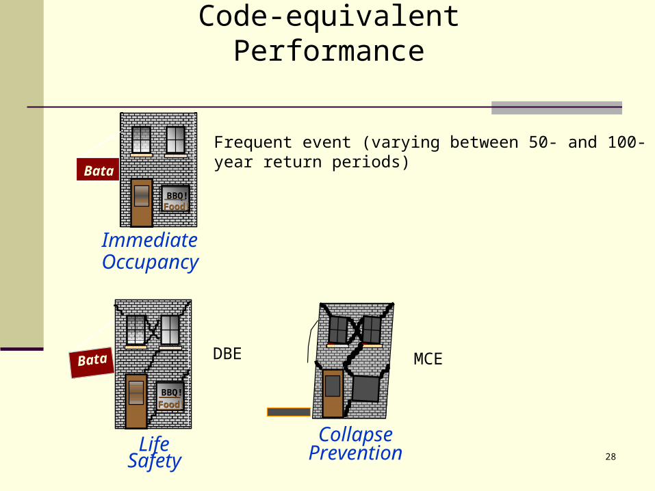
Code-equivalent Performance
Beer!Beer!Food!Food!
Joe’s
Beer!Beer!Food!Food!BBQ!Food!Food!
Joe’sBata
ImmediateOccupancy
Frequent event (varying between 50- and 100- year return periods)
Beer!Beer!Food!Food!
Joe’s
Beer!Beer!Food!Food!BBQ!Food!Food!
Bata
LifeSafety
DBE
CollapsePrevention
MCE
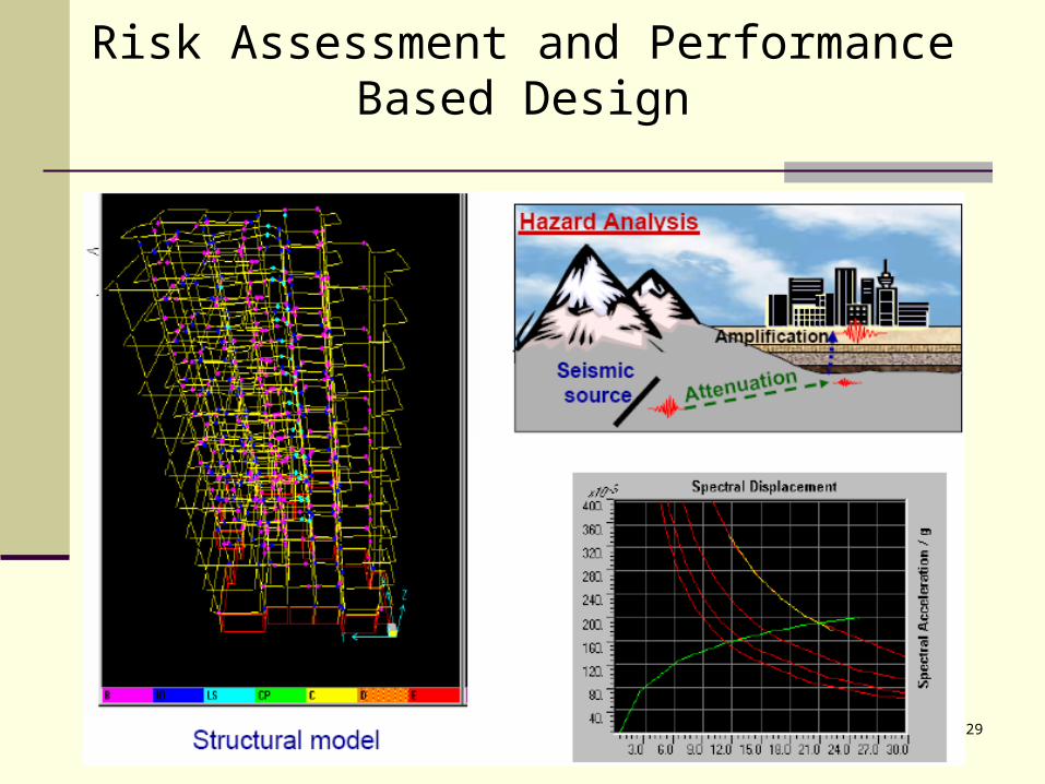
29
Risk Assessment and Performance Based Design

30
Thank you