byd battery-box premium hvs/hvm service guideline and
TRANSCRIPT

BYD Battery-Box Premium HVS/HVM Service Guideline and Checklist Version 1.4 Valid for HVS 5.1 / 7.7 / 10.2 / 12.8
HVM 8.3 / 11.0 / 13.8 / 16.6 / 19.3 / 22.1
Make sure to always use the latest version of this service document, available at: www.bydbatterybox.com
Important: The installation and all other kinds of works or measurements in combination with the Battery-Box Premium are only allowed by professional and qualified electricians. This checklist is a shortened assistance for the Battery-Box and does not replace the original manual, which can be found on www.bydbatterybox.com / www.eft-systems.de / www.alpspower.com.au. Subject to technical modifications; no responsibility is accepted for the accuracy of this information. Attention: High Voltage! Improper handling can cause danger and damage.

CONTENT 2
1. GENERAL STEPS 3
2. ERROR ANALYSIS 4 2.1 BCU shows no reaction / No LED 4 2.2 BCU switch cannot be pulled up / LED remains on 4 2.3 Communication problem with Inverter 5 2.4 Problem with the Firmware Update / App Configuration / Battery WIFI 6 2.5 Be Connect Plus (BCP) 7 2.6 BCU LED event code (EC) 8 2.7 Visual Check 9 2.8 Voltage measurement and undervoltage 10 2.9 Identifying a faulty module 11
3. SERVICE TASKS 12 3.1 BCU replacement 12 3.2 Module Replacement 12
SERVICE CHECKLIST AND CONTACT INFORMATION 13
2
CONTENT
Make sure to always use the latest version of this service document, available at: www.bydbatterybox.com Please proceed first with the installation steps by:
3
1. GENERAL STEPS
No. Name Description
1 Configuration Check if the configuration is correct. Refer to latest “BYD Battery-Box Premium HVS & HVM Compatible Inverter List” (V1.8 or above) available at: www.bydbatterybox.com Make sure the inverter is configured correctly.
2 Only HVS or HVM Do not mix up HVS-modules (“I”) with HVM-modules (“II”).
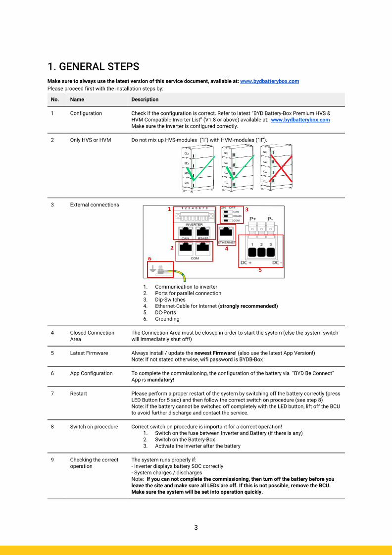
3 External connections
1. Communication to inverter 2. Ports for parallel connection 3. Dip-Switches 4. Ethernet-Cable for Internet (strongly recommended!) 5. DC-Ports 6. Grounding
4 Closed Connection Area
The Connection Area must be closed in order to start the system (else the system switch will immediately shut off!)
5 Latest Firmware
Always install / update the newest Firmware! (also use the latest App Version!) Note: If not stated otherwise, wifi password is BYDB-Box
6 App Configuration To complete the commissioning, the configuration of the battery via “BYD Be Connect” App is mandatory!
7 Restart Please perform a proper restart of the system by switching off the battery correctly (press LED Button for 5 sec) and then follow the correct switch on procedure (see step 8) Note: if the battery cannot be switched off completely with the LED button, lift off the BCU to avoid further discharge and contact the service.
8 Switch on procedure Correct switch on procedure is important for a correct operation! 1. Switch on the fuse between Inverter and Battery (if there is any) 2. Switch on the Battery-Box 3. Activate the inverter after the battery
9 Checking the correct operation
The system runs properly if: - Inverter displays battery SOC correctly - System charges / discharges Note: If you can not complete the commissioning, then turn off the battery before you leave the site and make sure all LEDs are off. If this is not possible, remove the BCU. Make sure the system will be set into operation quickly.
2.1 BCU shows no reaction / No LED LEDs do not light up, although the system switch is ON.
2.2 BCU switch cannot be pulled up / LED remains on The system switch switches off immediately (within 5 seconds) / LED remains on eventhough system switch is down
4
2. ERROR ANALYSIS
No. Name Description
10 Module quantity Check if module quantity fulfills minimum requirement (HVS: 2, HVM: 3 modules)
11 Voltage measurement See step 2.8
12 Use correct turn on procedure
NOTE: It is important that the battery is switched on before the inverter! Else, the BCU might not start properly. 1. Switch off the inverter and battery 2. Unplug all cables from the BCU (communication, DC, grounding), close panel 3. Lift BCU from the tower, then place the BCU back on the tower 4. Switch on the BCU. → The LED should light up again 5. Properly switch off BCU by pressing power button for 5 seconds 6. Open panel and connect external cables again (please check for communication wiring and preferably use CAT7). Close panel 7. Switch on the battery first, then switch on inverter Alternative: Switch off inverter and battery, wait for 30 minutes, turn on battery first, then turn on inverter
13 BCU exchange Only if cover is closed and voltage look good: Test another BCU, if available.
No. Name Description
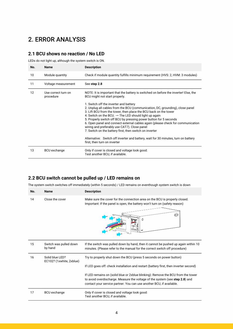
14 Close the cover Make sure the cover for the connection area on the BCU is properly closed. Important: If the panel is open, the battery won’t turn on (safety reason)
15 Switch was pulled down by hand
If the switch was pulled down by hand, then it cannot be pushed up again within 10 minutes. (Please refer to the manual for the correct switch off procedure)
16 Solid blue LED? EC102? (1xwhite, 2xblue)
Try to properly shut down the BCU (press 5 seconds on power button) If LED goes off: check installation and restart (battery first, then inverter second) If LED remains on (solid blue or 2xblue blinking): Remove the BCU from the tower to avoid overdischarge. Measure the voltage of the system (see step 2.8) and contact your service partner. You can use another BCU, if available.
17 BCU exchange Only if cover is closed and voltage look good: Test another BCU, if available.

2.3 Communication problem with Inverter
5
No. Name Description
18 Configuration Check if the configuration is correct. Refer to latest “BYD Battery-Box Premium HVS & HVM Compatible Inverter List” (V2.0 or above) available at: www.bydbatterybox.com Make sure the inverter is configured correctly.
19 Check DIP Switch If only one tower is in use (no parallel connection), all DIP switches should be in position: LEFT (except for Kostal PIKO MP plus - refer to manual)
If multiple HVS/HVM are in parallel connection, see manual for DIP configuration
20 Communication cable - Confirm PIN / Cable Configuration for the specific inverter model - Replace the communication cable (min. CAT5!)
21 Use another available communication port
Dependent on the Inverter model, one or two of the three options of communication ports shown below can be used (refer to the manual!). Please try the other port and communication option if available for the inverter.
22
Grounding Connect Battery-Box directly to the ground-bus of the house (do not connect over inverter casing!). Only with a correct grounding of the battery, a trouble-free and secure data transmission can be guaranteed. Use the correct connection, see picture:
23 App Configuration and Firmware
Please check if the App configuration was successful and the Firmware is the most recent one. If there are problems, please refer to Section 2.3 and 2.4
24 Restart the entire system - Switch off the Inverter - Switch off the battery (Press LED for 5 seconds until system switch falls - Note: if the Battery LED does not turn off afterwards, please contact the service) - Wait for 2 Minutes, Turn on the Battery first and then inverter second - Important: Please make sure the DC cable connection between battery and inverter is good and if there is a switch in between, it is open. The DC connection will prevent the system from operation, if it is not correct.

2.4 Problem with the Firmware Update / App Configuration / Battery WIFI The BCU consists of two components: the BMU and the BMS. The Firmware Update from the App will update the BMU, which will then update the BMS. The BMS will only be updated once there is communication between the battery and the inverter or just after the App configuration. It can take up to 20 Minutes until the firmware is updated on the BMS.
6
No Name Description
25 Correct App and Firmware
Make sure to have the latest App Version (>1.6.2) and Battery Firmware (download inside the App) on your mobile device before connecting the app with the battery WiFi. If the App cannot be installed, or other general Problems occur with the App:
- try with a different mobile device - Deinstall and reinstall the App - or try with PC Tool BCP (section 2.5).
26 WIFI cannot be found With the latest firmware, the Battery WIFI will turn off 5 hours after the start of the Battery. To reactivate the WIFI, press the LED button about 1 second or restart the system. To reset the WIFI, press the LED button three times 1 second within 6 seconds.
27 App reports: “Data connection busy”/“Data connection failure.”
Battery-Box is busy (e.g the battery could be updating the firmware). Please wait 10 minutes and try again.
28 BMS Version not updated
The App will only update the BMU. The BMU will update the BMS, but only if there is a stable and correct communication with the inverter or just after the configuration with the App. Once the BMU is updated and the inverter communication is established correctly or right after the configuration is done, the BMS update can take about 20 Minutes If the BMS Version is not updated after 20min with stable inverter communication, follow the below Process:
1. Update Firmware through the App again 2. Restart the system
a. Switch off the Inverter first, then switch off the battery second (Press LED for 5 seconds)
b. Wait for 30 Seconds c. Turn on the Battery first, then turn on the inverter second
3. Wait for 20 Minutes 4. Check BMS Firmware Version again with App. If Version is still wrong, do the
update process again (if possible with another mobile device).

2.5 Be Connect Plus (BCP) Be Connect Plus is a PC tool. With Be Connect Plus (BCP) you can:
- read the battery information, - configure the battery system - update BMU & BMS firmware - Export / download battery logs
BCP is constantly being improved and updated. Make sure to use the latest program version. You can download the latest version of the Tool on www.bydbatterybox.com / www.eft-systems.de / www.alpspower.com.au. For the service analysis, please download and provide the data / logs as described in the program instructions (see PDF manual inside of program ZIP archive). Note: You need a windows computer that will be connected to the battery Wifi.
7
2.6 BCU LED event code (EC) A constant white LED refers to standby mode. White blinking means charge or discharge. When the battery is initiating, the LED will flash white and blue with an interval time of 0.5 seconds (normal during startup). When the LED flashes blue with an interval time of 1 second it indicates an event code. We start to count when the white LED begins to flash, then we count how many times white and blue LED flashes. (also refer to the manual!) Examples: 1xwhite, 3xblue → EC 103 1xwhite, 11xblue → EC 111 3xwhite, 3xblue → EC 303 Most Errors come from a faulty communication line, incorrect app configuration or missing restart after app-configuration. Please go in detail through: Section 2.3 & 2.4 Note: if the battery is not correctly configured with the app, the event code (EC) might be misleading.
8
Event Code (EC) Measure
EC 101 EC 102
- Check DC-cable connection on battery, inverter and combiner box (if there is any). If problem remains: Test another BCU if available. - Try to properly shut down the BCU (press 5 seconds on power button) If LED goes off: check installation and restart (battery first, then inverter second). If LED remains on (solid blue or 2xblue blinking): Remove the BCU from the tower to avoid overdischarge. Measure the voltage of the system (see step 2.8) and contact your service partner. You can try another BCU, if available.
EC 103
- make sure all dip switches are in the correct position (For most configurations all on the left side (exception e.g. parallel connection and Kostal Piko MP). Refer to Manual!) - Remove the topmost module and check whether the event code disappears. If not, test another BCU if available. Note: A module with communication problems often works without restrictions at the lowest module position, since no communication with the stand is necessary.
EC 203 EC 303 EC 403 EC 503 EC 603 EC 703 EC 803
- Make sure app-configuration has been completed correctly (especially module type and quantity!). - Check whether the firmware is the latest. If not, update to the latest version firmware. - EC 203 to EC 803 means that a module is not recognized. The first number (= number of white flashes) indicates which module is probably affected. This module, or the module above it, can be responsible for the event code. Example: EC 203 = second module from the top / EC 403 = fourth-top module. - Check the modules for bent PINs (visual inspection, see section 2.7) - Remove the affected module and check whether the event code disappears. If not, check the module above. - Rearrange the modules in the tower. Note: A module with communication problems often works without restrictions at the lowest module position, since no communication with the stand is necessary.
EC 106 Make sure that the latest firmware is installed and that the battery has been properly restarted. If the problem remains: Test another BCU if available.

2.7 Visual Check The PINs should not be bent. A module with twisted pins will still work as long as it is the bottom module in the tower. So if you find twisted pins in a module, make sure to position that module in the bottom of the tower.
9
EC 107
Undervoltage. - Shut down the system quickly to avoid further discharge. Check whether the system can shut down normally (by pressing the LED button for 5s). - If the system cannot shut down normally, lift the BCU - Follow section 2.8 (Voltage measurement and undervoltage instruction)
EC 108 - Check DC-cable connection on battery, inverter and combiner box (if there is any). - Restart system according to manual. (note: to properly shut down you need to press the button for 5 seconds. Make sure to start the battery before starting the inverter!) If problem remains: Test another BCU if available.
EC 109 Make sure that the latest firmware is installed and that the battery has been properly restarted. If problem remains: Probably caused by a module. Follow the “Module exclusion method” (see Section 2.9).
EC 110
Low Voltage. The system needs to charge very soon and should not be discharged further! 1. Shut down the system quickly to avoid further discharge. Check whether the system can shut down normally (by pressing the LED button for 5s).
- If the system cannot shut down normally, lift the BCU - Follow section 2.8 (Voltage measurement and undervoltage)
2. Avoid further discharge of the battery, by searching the problem while the battery is completely off / BCU is lifted.
- Check the other steps in the service guideline and also check the inverter (latest FW / correct/defined restart?) and with the inverter service, why the force charge doesn’t work (e.g. any fault at the inverter). Do not turn on the battery before making sure the inverter should be able to charge the battery.
3. If everything has been checked and the system cannot be charged, make sure to avoid further overdischarge (e.g remove BCU) and contact the service.
EC 111
Normal when the battery has just started. It will turn to solid white when: - inverter communication works (--> Check inverter communication, Section 2.3 ) - right after saving / redoing the configuration (Be Connect: go through whole wizard // Be Connect Plus: resave the configuration by clicking on “Setup” and restart tool to refresh) Please also make sure all dip switches are in the correct position (For most configurations all on the left side (exception e.g. parallel connection and Kostal Piko MP). Refer to Manual!) If EC111 remains even after the inverter detects battery and even after redoing app configuration: Remove the topmost module and check whether the event code disappears. If not, test another BCU if available.
EC 112 Check inverter communication (Section 2.3)
10
2.8 Voltage measurement and undervoltage
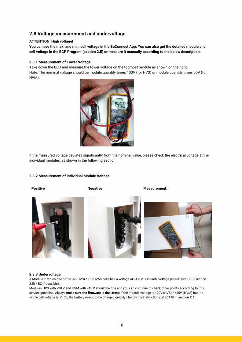
ATTENTION: High voltage! You can see the max. and min. cell voltage in the BeConnect App. You can also get the detailed module and cell voltage in the BCP Program (section 2.5) or measure it manually according to the below description: 2.8.1 Measurement of Tower Voltage Take down the BCU and measure the tower voltage on the topmost module as shown on the right. Note: The nominal voltage should be module quantity times 100V (for HVS) or module quantity times 50V (for HVM). If the measured voltage deviates significantly from the nominal value, please check the electrical voltage at the individual modules, as shown in the following section. 2.8.2 Measurement of Individual Module Voltage
2.8.3 Undervoltage A Module in which one of the 32 (HVS) / 16 (HVM) cells has a voltage of <1.5 V is in undervoltage (check with BCP (section 2.5) / BC if possible). Modules HVS with >90 V and HVM with >45 V should be fine and you can continue to check other points according to this service guideline. Always make sure the firmware is the latest! If the module voltage is <90V (HVS) / <45V (HVM) but the single cell voltage is >1.5V, the battery needs to be charged quickly - follow the instructions of EC110 in section 2.6
Positive
Negative
Measurement:
11
- If only one module is in undervoltage: remove that one and try commissioning without it (if the remaining modules still comply with the Compatible Inverter List). Otherwise, make sure to avoid further overdischarge (e.g. remove BCU) - If one, or all modules are in undervoltage: Contact the service as stated below and make sure to avoid any further discharge of the battery (e.g remove BCU from the system) When contacting the service, make sure to fill the service checklist completely and add the following information:
- Serial Numbers (of the BCU and all (affected) modules) - Tower voltage and individual module voltages of all modules (related to Serialnumber) - What was the status of the system switch on the BCU when the undervoltage (UV) happened? (tripped or not) - If possible: Logs from the battery using BCP (section 2.5) and Screenshots showing the cell voltages - Initial Firmware (FW) Version of the Battery when the UV happened (BMU and BMS) - Info if the BCU could shut down normally by pressing the LED button (note: if you have updated the FW after UV,
write down here whether the battery could be switched off manually before the FW update.) - Detailed description how and why the system reached Undervoltage if known. Information when the system was
installed and commissioned and in which circumstance and when the undervoltage happened. If the battery was never running before: Why did it never work before, and what was the Batteries status when the battery was left (on / off / LED).
- Inverter Model, Serial Number and Inverter Logs - Access to Inverter portal (add [email protected] and tell us the name of the system in the portal)
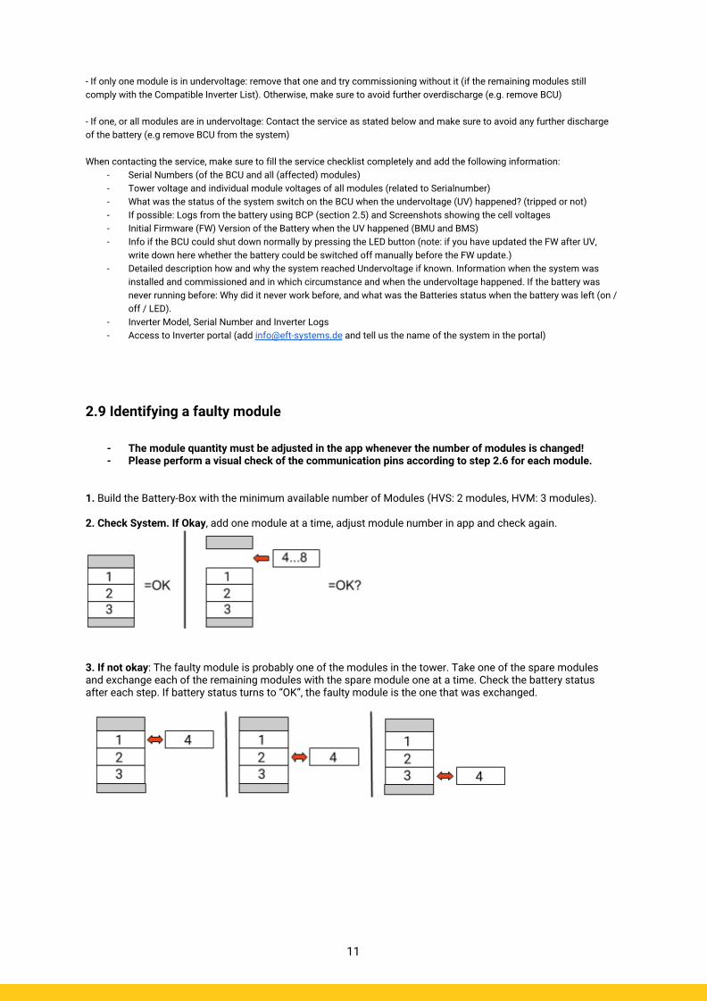
2.9 Identifying a faulty module
- The module quantity must be adjusted in the app whenever the number of modules is changed! - Please perform a visual check of the communication pins according to step 2.6 for each module.
1. Build the Battery-Box with the minimum available number of Modules (HVS: 2 modules, HVM: 3 modules). 2. Check System. If Okay, add one module at a time, adjust module number in app and check again.
3. If not okay: The faulty module is probably one of the modules in the tower. Take one of the spare modules and exchange each of the remaining modules with the spare module one at a time. Check the battery status after each step. If battery status turns to “OK”, the faulty module is the one that was exchanged.
3.1 BCU replacement Have you detected a faulty BCU?: After replacing the BCU, please do not forget to re-do the configuration and firmware-update in the app.
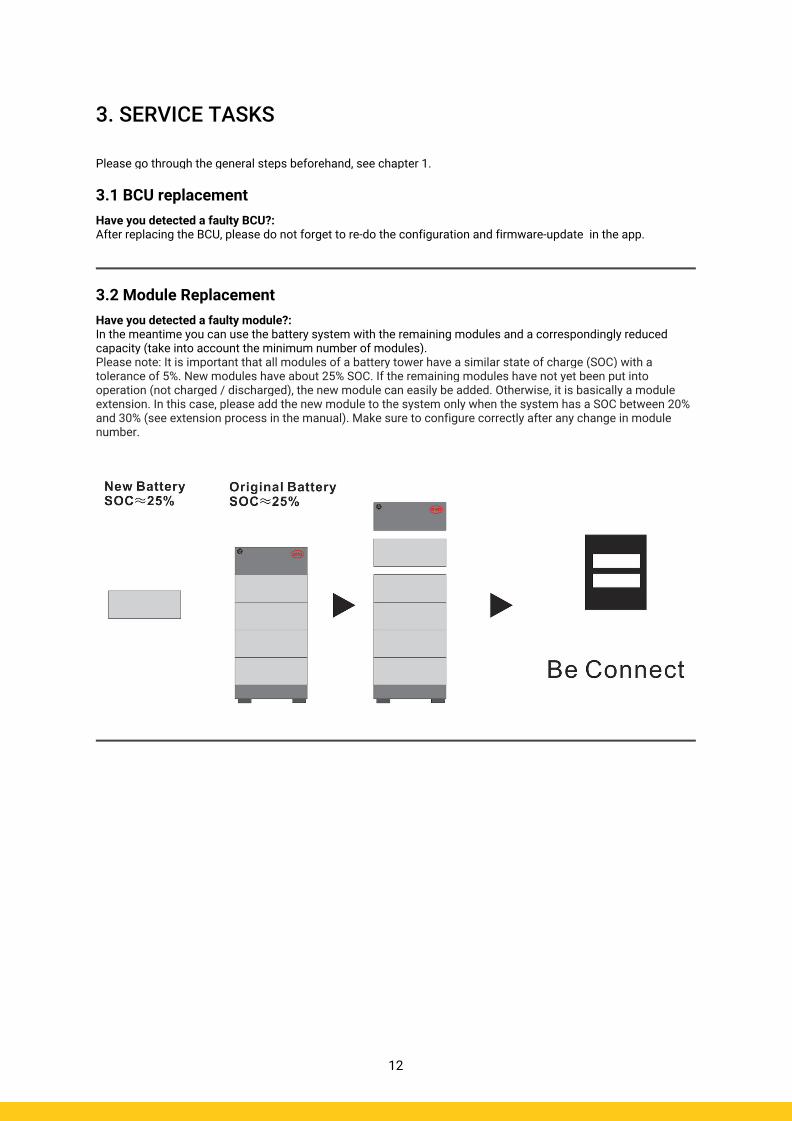
3.2 Module Replacement Have you detected a faulty module?: In the meantime you can use the battery system with the remaining modules and a correspondingly reduced capacity (take into account the minimum number of modules). Please note: It is important that all modules of a battery tower have a similar state of charge (SOC) with a tolerance of 5%. New modules have about 25% SOC. If the remaining modules have not yet been put into operation (not charged / discharged), the new module can easily be added. Otherwise, it is basically a module extension. In this case, please add the new module to the system only when the system has a SOC between 20% and 30% (see extension process in the manual). Make sure to configure correctly after any change in module number.
12
3. SERVICE TASKS Please go through the general steps beforehand, see chapter 1.

3.
2.
1.
Important: The installation and all other kinds of works or measurements in combination with the BYD Battery-Box are only allowed by professional and qualified electricians. Improper handling can cause danger and damage. This document does not replace the official BYD manuals and documents. No responsibility is accepted for the accuracy of the information..
BYD Battery-Box Premium HVS/HVM Service Checklist - V1.4 EN
Please fill all available information in below table. Some information like the Serial Number of the BCU is mandatory to receive service.
1.1 Configuration
1.2 Only HVS or HVM
1.3 External Connections
1.4 Closed Connection Area
1.5 Latest Firmware
1.6 App Configuration
1.7 Restart
1.8 Switch on Procedure
1.9 Correct Operation
SERVICE INFORMATION
GENERAL STEPS Please carefully check all 7 „General Steps“ from page 3 of the Service Guideline and confirm this in the boxes below
2.1 BCU shows no reaction / No LED
2.2 BCU switch shuts off immediately (within 5 seconds)
2.3 Communication problem with Inverter
2.4 Problem with the Firmware Update / App Configuration
ERROR RELATED ANALYSISPlease mark the error related Analysis from Chapter 2 (page 4-10) of the Service Guideline that you checked, and collect all the information related to those Sections
2.5 Be Connect Plus (BCP)
2.6 BCU LED event code
2.7 Visual Check
2.8 Voltage measurement
Company
Contact Person
Street / Nr.
ZIP / City
Phone
• Service Ticket Number or System ID:
• Installer / Delivery Address / Contact:
• System Information
Battery Configuration (HVS../HVM..)
BCU Serial Number
BCU Connected to Internet
Inverter Brand + Model
Inverter Serial Number
Commissioning Date
BMU Firmware
BMS Firmware
Inverter Firmware
Inverter Portal Name
(State the system name. Provide access)
• Service Information
Yes No
BCU EventCode (EC) Inverter Error Code
Was the battery charging / discharging before (was the system working normally before?)
Take pictures of open communication port in the BCU and Inverter clearly showing connection cables
Get Data of the Battery-Box with the Be Connect Plus (BCP) Programm (see chapter 2.5)
Yes No
Description of the Problem
Please provide any additional information that is necessary or could help in the analysis of the service case (e.g. serial number of a wrong module, video of a special behaviour; pictures; app screenshots; module voltages... )
By contacting us you confirm, that a qualified person has done the necessary control and collected all available information above.Service Contact: Europe: EFT-Systems GmbH Australia: Alps Power Pty Ltd www.eft-systems.de www.alpspower.com.au [email protected] [email protected] +49 9352 8523999 +61 02 8005 6688For Europe only: Register Ticket directly in the Online Service Center: https://support.eft-systems.de/
2.9 Identifying a faulty module