by order of the air force instruction 11-2f/qf · pdf filechapter 5—air-to-air weapons...
TRANSCRIPT

NOTICE: This publication is available digitally on the AFDPO WWW site at: http://afpubs.hq.af.mil.
COMPLIANCE WITH THIS PUBLICATION IS MANDATORY
BY ORDER OF THE SECRETARY OF THE AIR FORCE
AIR FORCE INSTRUCTION 11-2F/QF-4,VOLUME 3
1 JULY 2000
Flying Operations
F/QF-4--OPERATIONS PROCEDURES
OPR: HQ ACC/XOFS (Maj Warren A. Montgomery)
Certified by: HQ USAF/XOO(Brig Gen Robert D. Bishop, Jr.)
Supersedes MCR 55-4, 16 April 1993 Pages: 67Distribution: F
This volume implements AFPD 11-2, Aircraft Rules and Procedures; AFPD 11-4, Aviation Service; andAFI 11-202V3, General Flight Rules. It applies to all F-4 and QF-4 units. This publication does notapply to Air National Guard (ANG) or Air Force Reserve Command (AFRC) units and members. Majorcommands (MAJCOM)/direct reporting units (DRU)/field operating agencies (FOA) are to forward pro-posed MAJCOM/DRU/FOA-level supplements to this volume to HQ AFFSA/XOF, through HQ ACC/XOFS, for approval prior to publication in accordance with (IAW) AFPD 11-2. Copies of MAJCOM/DRU/FOA-level supplements, after approved and published, will be provided by the issuing MAJCOM toHQ AFFSA/XOF, HQ ACC/XOFS, and the user MAJCOM/DRU/FOA offices of primary responsibility(OPR). Field units below MAJCOM/DRU/FOA level will forward copies of their supplements to thispublication to their parent MAJCOM/DRU/FOA office of primary responsibility for post publicationreview. NOTE: The terms (DRU and FOA as used in this paragraph refer only to those DRUs/FOAs thatreport directly to HQ USAF. Keep supplements current by complying with AFI 33-360V1, PublicationsManagement Program. See paragraph 1.3. of this volume for guidance on submitting comments and sug-gesting improvements to this publication. Maintain and dispose of records created by processes pre-scribed in this volume IAW AFMAN 37-139, Records Disposition Schedule.
Chapter 1—INTRODUCTION 6
1.1. General ....................................................................................................................... 6
1.2. Waivers ...................................................................................................................... 6
1.3. Changes ...................................................................................................................... 6
Chapter 2—MISSION PLANNING 7
2.1. Responsibilities .......................................................................................................... 7
2.2. General Procedures .................................................................................................... 7

2 AFI 11-2F/QF-4V3 1 JULY 2000
2.3. Map/Chart Preparation ............................................................................................... 7
2.4. Briefing/Debriefing .................................................................................................... 7
2.5. Unit Developed Checklists/Local Aircrew Aids ....................................................... 8
Chapter 3—NORMAL OPERATING PROCEDURES 9
3.1. Ground Visual Signals ............................................................................................... 9
3.2. Cartridge Starts .......................................................................................................... 9
3.3. Taxi ............................................................................................................................ 10
3.4. Flight Line-up ............................................................................................................ 10
3.5. Before Takeoff Checks .............................................................................................. 10
3.6. Takeoff ....................................................................................................................... 10
3.7. Formation Takeoff ..................................................................................................... 10
3.8. Joinup/Rejoin ............................................................................................................. 11
3.9. Formation, General .................................................................................................... 11
3.10. Close Formation ......................................................................................................... 12
3.11. Tactical Formation ..................................................................................................... 12
3.12. Chase Formation ........................................................................................................ 13
3.13. Show Formation ......................................................................................................... 14
3.14. Maneuvering Parameters ........................................................................................... 14
Table 3.1. Airspeed/Altitude and AOA Restrictions .................................................................. 15
3.15. Operations Checks ..................................................................................................... 15
3.16. Radio Procedures ....................................................................................................... 16
3.17. Change of Aircraft Control Procedures ..................................................................... 17
3.18. General Low Altitude Procedures .............................................................................. 17
3.19. Air Refueling ............................................................................................................. 18
3.20. Night Operational Procedures .................................................................................... 18
3.21. Fuel Requirements ..................................................................................................... 19
3.22. Approaches and Landings .......................................................................................... 19
3.23. Overhead Traffic Patterns .......................................................................................... 20
3.24. Tactical Overhead Traffic Patterns ............................................................................ 20
3.25. Touch-and-Go Landings ............................................................................................ 20
3.26. Low Approaches ........................................................................................................ 21
3.27. Closed Traffic Patterns .............................................................................................. 21
AFI 11-2F/QF-4V3 1 JULY 2000 3
3.28. Back Seat Approaches and Landings ......................................................................... 21
3.29. Formation Approaches and Landings ........................................................................ 21
3.30. Automatic Flight Control System (AFCS) Restriction .............................................. 22
3.31. Crew Duties ............................................................................................................... 22
Chapter 4—INSTRUMENT PROCEDURES 26
4.1. Approach Category .................................................................................................... 26
4.2. Takeoff and Joinup .................................................................................................... 26
4.3. Trail Departures ......................................................................................................... 26
4.4. Formation Break-up ................................................................................................... 27
4.5. Formation Penetration ................................................................................................ 27
4.6. Formation Approach .................................................................................................. 27
4.7. Simulated Instrument Flight ...................................................................................... 27
Chapter 5—AIR-TO-AIR WEAPONS EMPLOYMENT 28
5.1. References .................................................................................................................. 28
5.2. Simulated Gun Employment ...................................................................................... 28
5.3. Maneuvering Limitations ........................................................................................... 28
Chapter 6—AIR-TO-SURFACE WEAPONS EMPLOYMENT 29
6.1. References .................................................................................................................. 29
6.2. Off-Range Attacks ..................................................................................................... 29
6.3. Weather Minimums ................................................................................................... 29
6.4. Pop-Up Attacks .......................................................................................................... 29
Chapter 7—ABNORMAL OPERATING PROCEDURES 30
7.1. General ....................................................................................................................... 30
7.2. Ground Aborts ........................................................................................................... 30
7.3. Takeoff Aborts ........................................................................................................... 30
7.4. Air Aborts .................................................................................................................. 30
7.5. Radio Failure .............................................................................................................. 31
7.6. Severe Weather Penetration ....................................................................................... 32
7.7. Lost Wingman Procedures ......................................................................................... 32
7.8. Spatial Disorientation (SD) ........................................................................................ 33
7.9. Armament System Malfunctions ............................................................................... 34

4 AFI 11-2F/QF-4V3 1 JULY 2000
7.10. Post Arresting Gear Engagement Procedures ............................................................ 35
7.11. In-flight Practice of Emergency Procedures .............................................................. 36
7.12. Search and Rescue (SARCAP) Procedures ............................................................... 36
Chapter 8—LOCAL OPERATING PROCEDURES 38
8.1. General ....................................................................................................................... 38
8.2. Procedures .................................................................................................................. 38
Chapter 9—QF-4 MANNED TARGET/AFCS PROCEDURES 39
9.1. General ....................................................................................................................... 39
9.2. Responsibilities .......................................................................................................... 39
9.3. General Manned Target Procedures .......................................................................... 40
9.4. Weather Restrictions and Operating Limits ............................................................... 40
9.5. Fuel Check Requirements .......................................................................................... 40
9.6. Chase Restrictions ...................................................................................................... 40
9.7. Landing Patterns ........................................................................................................ 41
9.8. Ordnance Release and Tank Jettison ......................................................................... 41
9.9. Mobile Control System (MCS) Pattern Rules of Engagement .................................. 41
Attachment 1—GLOSSARY OF REFERENCES AND SUPPORTING INFORMATION 43
Attachment 2—GENERAL BRIEFING GUIDE 46
Attachment 3—SPECIAL SUBJECT BRIEFING GUIDE 48
Attachment 4—ADVANCED HANDLING/INSTRUMENT BRIEFING GUIDE 49
Attachment 5—AIR REFUELING BRIEFING GUIDE 50
Attachment 6—AIR COMBAT TRAINING (ACBT)/INTERCEPT BRIEFING GUIDE 52
Attachment 7—LOW LEVEL NAVIGATION BRIEFING GUIDE 56
Attachment 8—AIR-TO-SURFACE WEAPONS EMPLOYMENT BRIEFING GUIDE-- RANGE MISSIONS 58
Attachment 9—AIR-TO-SURFACE WEAPONS EMPLOYMENT BRIEFING GUIDE-- SURFACE ATTACK TACTICS 62

AFI 11-2F/QF-4V3 1 JULY 2000 5
Attachment 10—CREW COORDINATION/PASSENGER/GROUND CREW BRIEFING GUIDE 66
Attachment 11—MISSION DEBRIEFING GUIDE 67

6 AFI 11-2F/QF-4V3 1 JULY 2000
Chapter 1
INTRODUCTION
1.1. General:
1.1.1. Scope. This volume outlines those procedures applicable to the safe operation of the F/QF-4aircraft. With the complementary references cited, this volume prescribes standard operational proce-dures to be used by all F/QF-4 aircrews.
1.1.2. Aircrew Responsibilities. This volume, in conjunction with other governing directives, pre-scribes procedures for F/QF-4 aircraft under most circumstances, but is not to be used as a substitutefor sound judgment or common sense. Operations or procedures not specifically addressed may beaccomplished if they enhance safe, effective mission accomplishment.
1.1.3. Deviations. Deviations from these procedures require specific approval of the HQ ACC/XOunless an urgent requirement or an aircraft emergency dictate otherwise, in which case the pilot incommand will take the appropriate action to safely recover the aircraft.
1.1.4. References. The primary references for F/QF-4 operations are: T.O.s 1F-4F-1, 1F-4(Q)E-1,1F-4E-1, 1F-4G-1, 1-1C-1, 1-1C-1-8; AFJI 10-220V1, Contractor’s Flight and Ground Operations;AFI 11-214, Aircrew, Weapons Director and Terminal Attack Controller Procedures for Operations;and this volume. Training units may develop phase manuals from the procedures contained in thesedocuments. Phase manuals may expand these basic procedures; in no case will they be less restrictive.
1.2. Waivers. Waiver requests will be forwarded through appropriate channels to the HQ ACC/XO forapproval. Waivers, if approved, will be issued for a maximum of 1 year from the effective date.
1.3. Changes. Submit recommendations for change to this volume on an AF Form 847, Recommenda-tion for Change of Publication, through channels, to HQ ACC/XOFS.
AFI 11-2F/QF-4V3 1 JULY 2000 7
Chapter 2
MISSION PLANNING
2.1. Responsibilities. The responsibility for mission planning is shared jointly by all flight members andthe operations and intelligence functions of fighter organizations.
2.2. General Procedures. Sufficient flight planning will be accomplished to ensure safe mission accom-plishment to include fuel requirements, map preparation, and takeoff and landing data.
2.3. Map/Chart Preparation:
2.3.1. Charts. Flight Information Publications (FLIP) en route charts may be used instead of mapson navigational flights within areas which are adequately covered by these charts.
2.3.2. Low Altitude Maps:
2.3.2.1. On low altitude flights, each aircraft in the flight will carry a minimum of one currentmap of the low altitude route/operating area. The map will be of such scale and quality that terrainfeatures, hazards, and chart annotations are of sufficient detail to allow individual navigation andsafe mission accomplishment.
2.3.2.2. Maps for low level navigation will be prepared and maintained as directed locally. High-light all man-made obstacles at or above the planned flight altitude. Additionally, annotate lowlevel maps with time and/or distance tick-marks to ensure positive positional awareness of obsta-cles along the planned route of flight plus or minus 5 NM.
2.3.2.3. Annotate all maps with a route abort altitude (RAA). Compute the RAA, for the entireroute/area, at a minimum of 1,000 feet above the highest obstacle/terrain feature (rounded up tothe next 100 feet) within the lateral limits of the route or training area, but in no case less than 5NM either side of the planned route corridor.
2.4. Briefing/Debriefing:
2.4.1. Flight leaders are responsible for presenting a logical briefing which will promote safe, effec-tive mission accomplishment. Briefing guides will be used to provide the flight leader/briefer with areference list of items which may apply to particular missions.
2.4.1.1. Items listed may be briefed in any sequence. Those items understood by all participantsmay be briefed as standard. Specific items not pertinent to the mission need not be covered.
2.4.1.2. When dissimilar aircraft are flown in formation, proper position (to ensure adequatewingtip clearance), responsibilities, and aircraft unique requirements will be briefed for eachphase of flight.
2.4.1.3. Briefings will begin at least 1.5 hours before scheduled takeoff.
2.4.1.4. Structure the flight briefing to accommodate the capabilities of each aircrew member inthe flight.
2.4.1.5. Weapon System Operators (WSO) should brief items applicable to rear cockpit dutiesduring the mission.

8 AFI 11-2F/QF-4V3 1 JULY 2000
2.4.1.6. Brief an appropriate alternate mission for each flight. The alternate mission will be lesscomplex than the primary and should parallel the primary mission. If not parallel, brief the spe-cific mission elements that are different. Unbriefed mission/events will not be flown.
2.4.1.7. Mission element/events may be modified and briefed airborne, if practical, and flightsafety is not compromised.
2.4.1.8. All missions will be debriefed.
2.4.2. Deployed Operations, Exercise, and Quick Turn Briefings. If all flight members attend aninitial or mass flight briefing, the flight lead on subsequent flights need brief only those items thathave changed from the previous flight(s).
2.4.3. Mission briefing guides are contained in the attachments. Units may supplement these guidesas necessary.
2.5. Unit Developed Checklists/Local Aircrew Aids:
2.5.1. Unit developed, expanded checklists may be used in lieu of flight manual checklists providedthey contain, as a minimum, all items, verbatim and in order, listed in the applicable checklist.
2.5.2. Units will produce an aircrew aid that, as a minimum, includes:
2.5.2.1. Briefing Guides.
2.5.2.2. Local UHF channelization and airfield diagrams.
2.5.2.3. Impoundment procedures, emergency action checklists and NORDO/divert information.
2.5.2.4. Barrier information at divert bases.
2.5.2.5. Bailout and Jettison Areas.
2.5.2.6. Cross-country procedures to include: command and control, Joint Oil Analysis Program(JOAP) samples, servicing.
2.5.2.7. Map of local training areas.

AFI 11-2F/QF-4V3 1 JULY 2000 9
Chapter 3
NORMAL OPERATING PROCEDURES
3.1. Ground Visual Signals. Normally, aircrew and ground crew will communicate by the intercom sys-tem during all start-engine, pretaxi, and End of Runway (EOR) checks. The intercom system, if operable,will also be used anytime maintenance technicians (specialists) are performing tasks on the aircraft toinclude "Redballs" on the ramp or at EOR. The aircrew will ensure that no system, which could pose anydanger to the ground crew, is activated prior to receiving proper acknowledgement from ground person-nel. When ground intercom is not used, visual signals will be in accordance with AFI 11-218, AircrewOperation and Movement on the Ground, and this volume. The crew chief will repeat the given signalwhen it is safe to operate the system. The following signals augment AFI 11-218:
3.1.1. TURN ON CNI GROUND POWER SWITCH. Cup hands over ears and point to left wheelwell with the left index finger. To turn off CNI power, repeat signal followed by a slicing motion withthe right index finger across throat.
3.1.2. START NUMBER TWO ENGINE. Rotate the hand at head level with the index and middlefingers extended to query "all clear." For the number one engine, use the index finger.
3.1.3. AUXILIARY AIR DOORS CLEAR. Form a clenched fist, palm down, extend the index andmiddle finger in a back and forth motion.
3.1.4. REFUELING RECEPTACLE OPEN/CLOSE. Display hand flat on top of the helmet withfingers extended. To open - raise fingers to the vertical position with heel of hand remaining station-ary. To close - reverse signal.
3.1.5. SLAT OVERRIDE CHECK. Make a "half-moon" arcing motion with the fist clenched palmdown and index finger extended. (Use the same signal to return the slats to the normal position.)
3.1.6. FLIGHT CONTROL CHECK. With clenched fist, make several circular movements as ifmoving the control stick around the cockpit. The crew chief will indicate the direction of travel ofeach flight control by the position of hands and arms. Rudder travel direction during yaw stab aug andemergency quick release lever engagement will be indicated by crew chiefs hand motions.
3.1.7. STAB AUG CHECK. Raise right hand, fist clenched followed by one, two, then three fingers,respectively, for yaw, roll, and pitch augmentation. The roll aug check will include both wings andeach check will be acknowledged by an "OK" signal from the crew chief.
3.1.8. LOWER/RAISE TAILHOOK. To lower, extend right fist, thumb down, and lower into hor-izontal palm of left hand. To raise, extend right fist, thumb up, and raise into horizontal palm of lefthand.
3.1.9. LOSS OF BRAKES WHILE TAXING. Lower tailhook.
3.1.10. GUN ARMAMENT CHECK. Point index finger forward with thumb upward simulating apistol and shake head "Yes" or "No."
3.1.11. ARMAMENT SAFETY OVERRIDE SWITCH "IN." Ground crewman places handsover head with right thumb pressed into palm of left hand. When switch is in, pilot gives "OK" signal.
3.2. Cartridge Starts. Cartridge starts require OG/CC or WEG/CC approval.

10 AFI 11-2F/QF-4V3 1 JULY 2000
3.3. Taxi:
3.3.1. Minimum taxi interval is 150 feet staggered or 300 feet in trail. Spacing may be reduced whenholding short of or entering the runway.
3.3.2. Quick Check and Arming. Place hands in view of ground personnel while the quick checkinspection, arming, or de-arming are in progress. If the intercom system is not used during EORchecks, the aircrew will establish and maintain visual contact with the maintenance team chief and/orweapons load chief to facilitate the use of visual signals.
3.3.3. Do not taxi in front of aircraft being armed/de-armed with forward firing ordnance.
3.4. Flight Line-up. Flights will line up as appropriate based on weather conditions, runway conditions,and runway width. Spacing between separated elements/flights will be a minimum of 500 feet. If forma-tion takeoffs are planned, wingmen must maintain wingtip clearance with their element leader. If runwaywidth precludes line-up with wingtip clearance between all aircraft in the flight, use 500 feet spacingbetween elements or delay run-up until the preceding aircraft/element has released brakes.
3.5. Before Takeoff Checks. After the "Before Takeoff Checks" have been completed and prior to take-off, all flight members will inspect each other for proper configuration and any abnormalities.
3.6. Takeoff:
3.6.1. Do not takeoff if the Runway Condition Reading (RCR) is less than 12.
3.6.2. Do not takeoff if the computed takeoff roll exceeds 80 percent of the available runway singleship or 70 percent for a formation takeoff.
3.6.3. Ensure a departure end cable is in place for all takeoffs and landings. Exceptions requiresquadron CC approval.
3.6.4. Takeoffs will be accomplished in afterburner.
3.6.5. Takeoff interval between aircraft/elements will be a minimum of 10 seconds. Takeoff intervalbehind a formation takeoff will be a minimum of 15 seconds. When joinup is to be accomplished ontop or when carrying live air-to-surface ordnance, takeoff interval will be increased to a minimum of20 seconds.
3.6.6. Aircraft/elements will steer toward the center of the runway at the start of the takeoff roll.
3.6.7. Aircraft will normally accelerate to 300 KIAS before coming out of afterburner.
3.7. Formation Takeoff:
3.7.1. Formation takeoffs are restricted to elements of two aircraft.
3.7.2. Elements will be led by a qualified flight leader unless an Instructor Pilot (IP) is in the element.
3.7.3. Aircraft will be within 3,000 pounds weight of each other and symmetrically loaded. For for-mation takeoff purposes, symmetrical loading is defined as those store loadings which will not requirea trim or control application to counter a heavy wing or yaw during takeoff and acceleration to climbairspeed.
3.7.4. Do not make formation takeoffs when:
AFI 11-2F/QF-4V3 1 JULY 2000 11
3.7.4.1. Runway width is less than 125 feet.
3.7.4.2. Standing water, ice, slush, or snow is on the runway.
3.7.4.3. The crosswind component including max gust exceeds 15 knots.
3.7.4.4. Loaded with live munitions (excluding air-to-air missiles, 20mm ammunition/gun pods,and chaff/flares).
3.7.4.5. Ferrying aircraft from contractor/depot facilities.
3.7.5. Formation Takeoff Procedures:
3.7.5.1. If the wingman overruns the leader, the leader will direct the wingman to assume the lead,at which time the wingman will select full afterburner, maintain his side of the runway, and makehis own takeoff.
3.7.5.2. Gear will be retracted after the flight leader observes the wingman to be safely airborne.Initial gear movement on the leader’s aircraft, head nod, or radio call is the signal for gear retrac-tion. Flaps will be raised 3 seconds after initiation of gear retraction.
3.8. Joinup/Rejoin:
3.8.1. Day weather criteria for a Visual Flight Rules (VFR) joinup underneath: ceiling 1,500 feet andvisibility 3 miles.
3.8.2. Flight leaders will maintain 350 KIAS until joinup is accomplished unless mission require-ments necessitate a different airspeed.
3.8.3. If a turning joinup is to be accomplished, the flight leader will not exceed 45 degrees of bank.
3.8.4. For further joinup procedures, see Night Operational Procedures (paragraph 3.23.) and Chap-ter 4.
3.9. Formation, General:
3.9.1. In Instrument Meteorological Conditions (IMC), maximum flight size is four aircraft exceptwhen flying in close formation with a tanker (refer to T.O. 1-1C-1-8).
3.9.2. Do not use exaggerated rolling maneuvers to maintain or regain position below 5,000 feetAbove Ground Level (AGL) or in airspace where aerobatics are prohibited.
3.9.3. Airborne visual signals will be in accordance with AFI 11-205, Aircraft Cockpit and FormationFlight Signals. When formation position changes are directed by radio, all wingmen will acknowl-edge prior to initiating the change. A radio call is mandatory when directing position changes at nightor under instrument conditions.
3.9.4. Flight leaders will not break up formations until each wingman has a positive fix from which tonavigate (visual, radar, Inertial Navigation System (INS), or TACAN).
3.9.5. Changing Leads:
3.9.5.1. During flight in limited visibility conditions (for example, haze, night, or IMC), initiatelead changes from a stabilized, wings level attitude.

12 AFI 11-2F/QF-4V3 1 JULY 2000
3.9.5.2. The minimum altitude for changing leads within a formation is 500 feet AGL over landor 1,000 feet AGL over water. For night or IMC, do not change leads below 1,500 feet AGL orradar downwind, whichever is lower.
3.9.5.3. Do not initiate lead changes with the wingman farther aft than normal fingertip or routeposition or greater than 30 degrees back from line abreast.
3.9.5.4. Prior to initiating the lead change, the leader will ensure that the wingman assuming thelead is in a position from which the lead change can be safely initiated and visual contact main-tained.
3.9.6. Battle Damage Checks. If circumstances permit, flight leads will direct a battle damage checkafter each mission prior to or during return to base (RTB). This check is mandatory following theexpenditure of ordnance (including all types of 20 mm ammunition), low level navigation flights, andACBT sorties exceeding 5 "Gs." Established deconfliction responsibilities and position change pro-cedures will be observed. Formation spacing will be no closer than normal fingertip.
3.10. Close Formation:
3.10.1. Echelon. Relative position is the same as fingertip. Turns into the echelon will be avoided.If a turn is made into the echelon, each aircraft will maintain the same relative position as in straightand level flight. On turns away from the echelon, the fuselages of all aircraft will be maintained in thesame horizontal plane.
3.10.2. Crossunders:
3.10.2.1. When the number two aircraft is required to cross under in a flight of three or more,number three (or the element) will move out to allow two sufficient spacing to move into position.Then number two will drop below and behind the leader maintaining nose-tail and vertical clear-ance and then move up into the wing position on number one. Number three will then move in onnumber two’s wing.
3.10.2.2. When an element is required to cross under, the element will drop below and behind thelead (element) maintaining nose-tail and vertical clearance, cross to the opposite side and thenmove up into position. Number four changes positions during the crossunder.
3.10.2.3. To return to fingertip formation, the flight leader will make a radio call.
3.11. Tactical Formation:
3.11.1. Apply the following rules for flight path deconfliction during tactical maneuvering:
3.11.1.1. Flight/element leads will consider wingman/element position and ability to safely per-form a maneuver before directing it.
3.11.1.2. Wingmen/elements maneuver relative to the flight lead/lead element and maintain sight.Trailing aircraft/elements will be responsible for deconflicting with lead aircraft/elements.
3.11.1.3. Wingmen/elements will cross above the lead/lead element for deconfliction when below1000 feet AGL.
3.11.2. Loss of Visual. The following procedures apply when one or more flight members/elementslose visual contact within the formation:

AFI 11-2F/QF-4V3 1 JULY 2000 13
3.11.2.1. If any flight member/element calls "Blind," then the appropriate flight member/elementwill immediately confirm a "Visual" with an informative call.
3.11.2.2. If the other flight member/element is also "Blind," then the flight leader will take actionto ensure altitude separation between flight members/elements. The flight lead will specify eitherAGL or MSL when directing the formation to deconflict. When directed to "deconflict," a mini-mum of 500 feet altitude separation will be used. Avoid climbs/descents through the deconflictionaltitude.
3.11.2.3. If there is no timely acknowledgment of the "Blind," call, then the flight member/ele-ment initiating the call will maneuver away from the last known position of the other flight mem-ber/element and alter altitude.
3.11.2.4. If visual contact is still not regained, the flight leader will take additional positive actionto ensure flight path deconfliction within the flight to include a Terminate/Knock-It-Off if neces-sary. Scenario restrictions such as sanctuary altitudes and/or adversary blocks must be considered.
3.11.2.5. Aircraft will maintain altitude separation until a visual is regained and, if necessary, willnavigate with altitude separation until mutual support is regained.
3.11.3. Two-Ship. The following rules apply for flight path deconfliction during tactical maneuver-ing of two-ship formations:
3.11.3.1. Normally, the wingman is responsible for flight path deconfliction.
3.11.3.2. The flight lead becomes primarily responsible for deconfliction when:
3.11.3.2.1. Tactical maneuvering places the leader in the wingman’s "blind cone" or forces thewingman’s primary attention away form the leader (e.g., wingman becomes engaged fighter)."
3.11.3.2.2. The wingman calls "Padlocked" or "Blind."
3.11.3.2.3. Primary deconfliction responsibility transfers back to the wingman once the wing-man acknowledges a visual on his lead.
3.11.4. Three/Four-Ship (or Greater). When flights of more than two aircraft are in tactical forma-tion:
3.11.4.1. Formation visual signals performed by a flight/element leader pertain only to the associ-ated element unless specified otherwise by the flight leader.
3.11.4.2. Trailing aircraft/element(s) will maintain a sufficient distance back so that primaryemphasis during formation maneuver/turns is on low altitude awareness and deconfliction withinelements, not on deconfliction between elements.
3.12. Chase Formation:
3.12.1. Restrictions. Any pilot may fly safety chase for another aircraft under emergency or impend-ing emergency conditions. All chase events may be flown by IP/Stan/Eval Flight Examiners (SEFEs)or upgrading IPs under the supervision of an IP. Qualified pilots (including Initial Qualification Train-ing/Mission Qualification Training pilots who have successfully completed an Instrument/Qualifica-tion Evaluation) may chase as safety observers for aircraft performing simulated instrument flight (butare not required) or hung ordnance patterns. Simulated emergency patterns may be chased by quali-fied flight leads.
14 AFI 11-2F/QF-4V3 1 JULY 2000
3.12.2. Procedures:
3.12.2.1. On transition sorties, the chase aircraft will perform a single ship takeoff. In-flight, thechase aircraft will maneuver as necessary but must maintain nose to tail separation. The chasewill not stack below the lead aircraft below 1,000 feet AGL. In the traffic pattern, the chase air-craft may maneuver as necessary to observe performance.
3.12.2.2. A safety observer in a chase aircraft will fly a position in a 30 to 60 degree cone withnose/tail clearance to 1,000 feet from which he can effectively clear and/or provide assistance.
3.12.2.3. For live ordnance missions, the chase aircrew is responsible for ensuring safe escape cri-teria is met for their aircraft.
3.13. Show Formation. These formations will be specifically briefed and flown in accordance with(IAW) AFI 11-209, Air Force Participation in Aerial Events (as supplemented). Refer to AFI 11-209 forspecific rules and appropriate approval levels to participate in static displays and aerial events.
3.14. Maneuvering Parameters:
3.14.1. Accomplish Rig checks IAW flight manual procedures. If external wing tanks are carried, arig check will be accomplished after the tanks indicate empty to ensure that the tanks are empty.
3.14.2. Stab aug/slat checks will be accomplished IAW flight manual procedures and are requiredprior to the performance of stalls, confidence maneuvers, ACBT, or any other maximum performance/high AOA maneuvering.
3.14.3. If an out-of-rig condition, malfunctioning stab aug, or asymmetrical load exists, do notmaneuver the aircraft at high AOA and fly a straight-in approach for landing. Chase ships will fly nocloser than route.
3.14.4. The roll channel of the stab aug will be disengaged for ACBT, stalls, confidence maneuversand other maneuvers in which rudder rolls or reversals will be accomplished.
3.14.5. External wing tanks will be empty prior to performing diving weapons delivery patterns,stalls, confidence maneuvers, aerobatics (except Lazy Eights and Chandelles), ACBT or advancedhandling maneuvers.
3.14.6. Altitude Restrictions:
3.14.6.1. Aircraft will not descend below 5,000 feet AGL during aerobatic maneuvering or stallrecoveries.
3.14.6.2. Minimum recovery altitude for Confidence Maneuvers is 10,000 feet AGL.
3.14.6.3. Minimum entry altitude for approaches to stalls (clean and configured) is 15,000 feetAGL. Maximum altitude for stall entry is 25,000 feet MSL.
3.14.6.4. If accelerated stall indications have not been observed before decelerating through 300KIAS, discontinue the maneuver.
3.14.7. Airspeed/AOA Restrictions:
3.14.7.1. Flight maneuvering, except stall demonstrations and confidence maneuvers, is limitedto a maximum of 25 units AOA, excessive wing rock, or 175 KIAS, whichever occurs first. Whenthese limits are exceeded, aircrews will devote primary attention to regaining an AOA condition

AFI 11-2F/QF-4V3 1 JULY 2000 15
of 25 units or less, and airspeed at/or above 175 KIAS. Should any delay be incurred in reestab-lishing operating parameters within these maximum and minimum limits, a "Terminate"/"Knock-it-off" will be initiated. Airspeed decreasing to 150 KIAS will result in an immediate"Terminate"/"Knock-It-Off" and recovery.
3.14.7.2. Confidence maneuvers and indexer light orientations are limited to 120 KIAS mini-mum.
3.14.7.3. Stall maneuvering demonstrations are limited to 120 KIAS, a maximum of 29 unitsAOA, nose rise, nose slice, 30 degrees of wing rock, or build-up of side forces. (Configured stalldemonstrations will be terminated at the pedal shaker.)
3.14.8. Flight through wingtip vortices/jet wash should be avoided. If unavoidable, the aircraftshould be unloaded immediately to approximately 1 G.
3.14.9. Manually selected flaps will not be used as an in-flight maneuvering aid in an attempt toimprove aircraft performance.
3.14.10. Approaches to Stalls/Confidence Maneuvers:
3.14.10.1. An IP is required in the aircraft for all stall demonstrations.
3.14.10.2. Stalls and confidence maneuvers will not be performed with an asymmetrically loadedaircraft.
Table 3.1. Airspeed/Altitude and AOA Restrictions.
3.15. Operations Checks:
ALTITUDE MINIMUM AIRSPEED
MAXIMUMAOA
NOTES
Aerobatics 5,000 feet AGL Minimum 175 KIAS 25 Units 1, 2
Confidence Maneuvers
Recover above 10,000 ft AGL
300 KIAS entry. 120 KIAS during maneuver.
25 Units 1, 2
StallDemonstrations
Enter between 15,000 feet AGL and 25,000 feet MSL. Recover above 5,000 feet AGL.
120 KIAS 29 Units (Clean)25 Units (Conf)
1, 3
AdvancedHandling/ACBT
5,000 feet AGL Minimum 175 KIAS 25 Units 1, 2
Low Altitude Navigation
500 feet AGL (300 feet AGL WIC)
300 KIAS 25 Units 1, 2, 4
Notes:1. Stab Aug/Slat check required.
2. Roll stab aug will be disengaged.
3. Instructor pilot required.
4. Minimum airspeed during offensive or defensive maneuvering is 350 KIAS.

16 AFI 11-2F/QF-4V3 1 JULY 2000
3.15.1. Sufficient operations checks will be accomplished to ensure safe mission accomplishment.Frequency will be increased during tactical maneuvering at high power settings. Operations checksare mandatory:
3.15.1.1. During climb or at level off after takeoff.
3.15.1.2. When external fuel tanks are empty.
3.15.1.3. Prior to each (D) ACBT engagement or intercept.
3.15.1.4. Prior to entering an air-to-surface range, once while on the range if multiple passes aremade and after departing the range.
3.15.2. Minimum items to check are engine instruments, total and internal fuel quantities, G-suit con-nection, oxygen system, cabin altitude and G-meter.
3.15.3. For formation flights, the flight leader will initiate ops checks by radio call or visual signal.
3.15.3.1. Response will be made by radio call or visual signal. It will include tape over counterreadings. (EXCEPTION: Total fuel only may periodically be used during high demand phasesof flight.)
3.15.3.2. For mandatory operations checks, when external fuel tanks are carried, each flight mem-ber will check the external tank(s) and add "Tank(s) feeding/empty" to the ops check. Once thetank(s) have been confirmed and called empty, this may be omitted from subsequent ops checks.
3.16. Radio Procedures:
3.16.1. Preface all communications with the complete flight call sign (except for wingman acknowl-edgment). Transmit only that information essential for accomplishment of the mission or to promotesafety of flight. Do not use any radio as a flight "intercom." Use visual signals whenever practical.
3.16.2. Make a "Terminate"/"Knock-It-Off" radio call to terminate maneuvering for any reason, par-ticularly when a dangerous situation is developing. This transmission may be made by any flightmember, and applies to all phases of flight and all types of missions. All participants will acknowl-edge by repeating the call in turn.
3.16.3. The flight/mission lead will initiate all radio checks and channel changes.
3.16.4. Acknowledge radio checks which do not require the transmission of specific data by individ-ual flight members in turn. Acknowledgement by the individual flight member indicates the appropri-ate check will be initiated or is in the process of being completed.
3.16.5. In addition to the standard radio procedures outlined in AFMAN 11-217V1, Instrument FlightProcedures; AFI 11-202V3, Specific Mission Guides; and FLIP, the following radio transmissions arerequired:
3.16.5.1. All flight members will acknowledge understanding the initial Air Traffic Control(ATC) clearance.
3.16.5.2. Gear Checks. Each pilot will make an individual gear check on base leg or if making aVFR straight-in approach not later than 3 miles on final. When conducting instrumentapproaches, gear checks will be made in response to ATC instructions or no later than the finalapproach fix. The wingman or chase need not make this call during a formation or chasedapproach.

AFI 11-2F/QF-4V3 1 JULY 2000 17
3.16.6. Use brevity code and other terminology IAW AFI 11-214 and local standards.
3.17. Change of Aircraft Control Procedures. Both aircrew members must know at all times who hascontrol of the aircraft. Transfer of aircraft control will be made with the statement "You have the aircraft."The aircrew member receiving control of the aircraft will acknowledge "I have the aircraft," Once assum-ing control of the aircraft, maintain control until relinquishing it as stated above. (EXCEPTION: If theintercom fails, the pilot in the front cockpit, if not in control of the aircraft, will shake the stick and assumecontrol of the aircraft, radios, and navigational equipment unless otherwise briefed.)
3.18. General Low Altitude Procedures:
3.18.1. Low level formation positions/tactics will be flown IAW the appropriate phase manuals.
3.18.2. Line abreast formation is authorized at or above 300 feet AGL.
3.18.3. During briefings, emphasis will be placed on low altitude flight maneuvering and observationof terrain features/obstacles along the route of flight. For low altitude training over water or feature-less terrain, include specific considerations for operations with emphasis on minimum altitudes andspatial disorientation.
3.18.4. At altitudes below 1,000 feet AGL, wingman will not fly at a lower AGL altitude than lead.
3.18.5. If unable to visually acquire or ensure lateral separation from known vertical obstructionswhich are a factor to the route of flight, flight leads will direct a climb not later than 3 NM prior to theobstacle to ensure vertical separation.
3.18.6. When crossing high or hilly terrain, maintain positive G and do not exceed approximately 120degrees of bank. Maneuvering at less than 1 G is limited to upright bunting maneuvers.
3.18.7. Minimum airspeed for low level navigation, including low level route entry, is 300 KIAS.
3.18.8. The radar altimeter will be on and set to the briefed minimum altitude.
3.18.9. Minimum Altitudes. The aircrews minimum altitude will be determined and certified by theunit commander IAW local guidance. Pilots participating in approved step-down training programswill comply with the requirements and restrictions of that program. Minimum altitude for pilots whohave not completed the step-down training program is 1000 feet AGL. The following minimum alti-tudes apply to low level training unless higher altitudes are specified by national rules, route restric-tions or a training syllabus.
3.18.9.1. 500 feet AGL for:
3.18.9.2. Flying Training Unit (FTU) students and instructors when conducting training IAWapplicable syllabus.
3.18.9.3. Over water flight if duration is more than 1 minute, if out of sight of land, or if there isan indefinite horizon.
3.18.9.4. F-4s will not fly night or IMC low levels.
3.18.10. During all low altitude operations, the immediate reaction to task saturation, diverted atten-tion, knock-it-off or emergencies is to climb to a prebriefed safe altitude (minimum 1,000 feet AGL).

18 AFI 11-2F/QF-4V3 1 JULY 2000
3.18.11. Weather minimums for visual low level training will be 1,500 feet and 3 miles for any routeor area, or as specified in FLIP for Military Training Routes/unit regulations/national rules, whicheveris higher.
3.18.12. Low Level Route/Area Abort Procedures:
3.18.12.1. Compute and brief a low level route abort altitude (RAA) IAW paragraph 2.3.2.3.
3.18.12.2. Visual Meteorological Conditions (VMC) route/area abort procedures:
3.18.12.2.1. Maintain safe separation from the terrain. (2000 feet AGL minimum.)
3.18.12.2.2. Comply with VFR altitude restrictions and squawk applicable Identification,Friend or Foe (IFF)/Selective Identification Feature (SIF) modes and codes.
3.18.12.2.3. Maintain VMC at all times. If unable, follow IMC procedures outlined below.
3.18.12.2.4. Attempt contact with controlling agency, if required.
3.18.12.3. IMC route/area abort procedures:
3.18.12.3.1. Immediately climb to or above the briefed RAA.
3.18.12.3.2. Maintain preplanned ground track. Execute appropriate lost wingman proce-dures if necessary.
3.18.12.3.3. If deviations from normal route/area procedures are required, or if the RAA ishigher than the vertical limits of the route/area, squawk emergency.
3.18.12.3.4. Attempt contact with the appropriate ATC agency for an Instrument Flight Rules(IFR) clearance. If required to fly in IMC without an IFR clearance, cruise at appropriate VFRhemispheric altitudes until IFR clearance is received.
3.19. Air Refueling. Pilots undergoing initial/recurrency training in air refueling will not refuel with astudent boom operator.
3.20. Night Operational Procedures:
3.20.1. Night Ground Operations. When ground personnel are working under the aircraft, the exte-rior light flasher switch will be placed to steady. Taxi spacing will be a minimum of 300 feet and onthe taxiway centerline. The taxi light will normally be used during all night taxiing. (EXCEPTION:When the light might interfere with the vision of the pilot of an aircraft landing or taking off, the taxi-ing aircraft will come to a stop if the area cannot be visually cleared without the taxi light.) For for-mation takeoffs, flight/element leaders will turn lights to DIM or BRIGHT-STEADY when reachingthe run-up position on the runway. Wingmen will maintain lights at BRIGHT-FLASH for takeoffs.All aircraft will turn formation strip lights on.
3.20.2. Night Takeoff. During a night formation takeoff, brake release and configuration changeswill be called on the radio. Following takeoff, each aircraft/element will climb on runway heading to1,000 feet AGL before initiating turns, except where departure instructions specifically preclude com-pliance.
3.20.3. Night Joinup. Weather criteria for night joinup underneath a ceiling is 3,000 feet and 5miles. After joinup, position lights to DIM or BRIGHT-STEADY for all except the last aircraft,which will maintain BRIGHT-FLASH unless otherwise directed by the flight lead.

AFI 11-2F/QF-4V3 1 JULY 2000 19
3.20.4. Night Formation Procedures:
3.20.4.1. When in positions other than fingertip or route, aircraft spacing will be maintained pri-marily by instruments, radar and/or timing with visual reference secondary. If aircraft spacingcannot be ensured, then altitude separation (minimum of 1,000 feet) will be established. At alltimes, aircrews will cross check instruments to ensure ground clearance.
3.20.4.2. Do not change lead or wing positions below 1,500 feet AGL or Ground ControlledApproach (GCA) downwind altitude, whichever is lower. Lead and position changes will becalled over the radio and should be initiated from a stabilized, wings level altitude.
3.20.5. Night Break-Up. Prior to a night formation break-up, the flight leader will transmit attitude,altitude, airspeed, and altimeter setting, which will be acknowledged by wingmen. Wingmen will alsoconfirm good navigational aids.
3.20.6. Night Landing. Night landings will normally be accomplished from a straight-in approach.Refer to AFI 11-202V3 as supplemented for specific procedures.
3.20.7. Night formation landings will only be performed when required for safe recovery of the air-craft.
3.21. Fuel Requirements:
3.21.1. Normal Recovery Fuel. The fuel on initial or at the FAF at the base of intended landing oralternate, if required. Fuel quantity will be 2,000 pounds (2,500 pounds for FTU students flying crewsolo).
3.22. Approaches and Landings:
3.22.1. The desired touchdown point for a VFR approach is 500 feet from the threshold.
3.22.2. Minimum pattern and touchdown spacing between landing aircraft is 3,000 feet for similaraircraft (e.g., F-4 versus F-4) or 6,000 feet for dissimilar aircraft (e.g., F-4 versus F-15) or as directedat the landing base, whichever is higher. Spacing should be increased whenever wake turbulence isanticipated.
3.22.3. Aircraft will land in the center of the runway and clear to the turnoff side of the runway whenspeed/conditions permit.
3.22.4. Landing Restrictions:
3.22.4.1. When the computed landing roll exceeds 80 percent of the available runway, select adifferent runway or land at an alternate, if possible.
3.22.4.2. When the RCR at the base of intended landing is less than 12, land at an alternate, if pos-sible. If an alternate is not available, make an approach-end arrestment.
3.22.4.3. Do not land over any raised web barrier (e.g., MA-1A, BAK 15).
3.22.5. Any pilot experiencing drag chute failure will make a radio call indicating drag chute failureand state intentions. If a cable engagement is anticipated, the aircraft should remain in the center ofthe runway.
3.22.6. Aircrews must accurately evaluate actual runway environment conditions, touchdown point,and speed when making no-chute landings. If circumstances suggest that safe operations cannot be

20 AFI 11-2F/QF-4V3 1 JULY 2000
ensured, then use the drag chute for landing. When an intentional no-chute landing is to be accom-plished, it must meet the following conditions:
3.22.6.1. Will be approved by squadron CC/DO in advance and briefed.
3.22.6.2. Only dry runway, daylight conditions.
3.22.6.3. The computed no-chute landing roll will be less than two-thirds of the available runway.(Computed from touchdown point.)
3.22.6.4. Operational arresting gear will be in place at the departure end of the runway.
3.22.6.5. Will not be performed during formation landings.
3.22.6.6. Runway will be completely clear of previous landing aircraft.
3.22.6.7. Zero tailwind component.
3.22.6.8. Advise ATC of intentional no-chute landings.
3.23. Overhead Traffic Patterns:
3.23.1. Overhead patterns can be flown with unexpended practice ordnance (including chaff andflares).
3.23.2. Initiate the break over the touchdown point or as directed.
3.23.3. The break will be executed individually in a level 180-degree turn to the downwind leg atminimum intervals of 5 seconds (except IP/SEFE chase or when in tactical formation).
3.23.4. Aircraft will be wings level on final at approximately 300 feet AGL and 1 mile from theplanned touchdown point.
3.24. Tactical Overhead Traffic Patterns. Tactical entry to the overhead traffic pattern is permittedwhen:
3.24.1. Published overhead pattern altitude is used.
3.24.2. Specific procedures are developed locally and coordinated with appropriate air traffic controlagencies.
3.24.3. No more than four aircraft are in the flight. Aircraft/elements more than 6,000 feet in trail areconsidered a separate flight.
3.24.4. No aircraft are offset from the runway in the direction of the break. The intent is to avoidrequiring a tighter than normal turn to arrive on normal downwind.
3.24.5. Normal downwind, base turn positions, and spacing are flown.
3.25. Touch-and-Go Landings:
3.25.1. Fly touch-and-go landings IAW AFI 11-202V3, as supplemented. (EXCEPTION: CaptiveQF-4 touch-and-go landings are authorized for pilot and/or remote controller continuation training).
3.25.2. Do not fly touch-and-go landings with live or hung ordnance or with fuel remaining in anyexternal tank (excluding unexpended chaff or flares).

AFI 11-2F/QF-4V3 1 JULY 2000 21
3.26. Low Approaches:
3.26.1. Observe the following minimum altitudes:
3.26.1.1. IP/SEFEs flying chase patterns - 50 feet AGL (100 feet AGL for QF-4 drone chase)
3.26.1.2. Formation low approaches - 100 feet AGL.
3.26.1.3. Chase aircraft during an emergency - 300 feet AGL unless safety or circumstances dic-tate otherwise.
3.26.2. During go-around, remain 500 feet below VFR overhead traffic pattern altitude until crossingthe departure end of the runway unless local missed approach/climbout procedures, or controllerinstructions dictate otherwise.
3.27. Closed Traffic Patterns. Initiate the pattern at the departure end of the runway unless directed/cleared otherwise by local procedures or the controlling agency. When in formation, a sequential closedmay be flown with ATC concurrence at an interval to ensure proper spacing.
3.28. Back Seat Approaches and Landings:
3.28.1. An upgrading IP may accomplish back seat landings only when an IP is in the front cockpit.
3.28.2. During back seat approaches and landings, the front seat pilot will visually clear the area,monitor aircraft parameters and configurations, and be prepared to direct a go-around or take controlof the aircraft (as briefed by the rear cockpit IP), if necessary.
3.29. Formation Approaches and Landings:
3.29.1. General:
3.29.1.1. Accomplish formation landings from the most precise approach available. Use a pub-lished instrument approach or a VFR straight-in approach using the Visual Approach Slope Indi-cator (VASI)/Precision Approach Path Indicator (PAPI), if available. In all cases, the rate ofdescent should be similar to a normal precision approach.
3.29.1.2. Continuation training formation landings will be led by a qualified flight leader unlessan IP is in the element.
3.29.1.3. Practice formation approaches will not be performed above 46,000 pounds gross weight(not applicable [N/A] for QF-4).
3.29.2. Formation Landing Restrictions:
3.29.2.1. Aircraft will be symmetrically loaded (as defined in paragraph 3.8.3.).
3.29.2.2. Establish an approach speed 10 knots higher than computed for the heavier aircraft.
3.29.2.3. Position the wingman on the upwind side if the crosswind component exceeds 5 knots.
3.29.3. Formation Landings are Prohibited:
3.29.3.1. When the crosswind component, including max gust, exceeds 15 knots.
3.29.3.2. When the runway is reported wet; or ice, slush, or snow are on the runway.
3.29.3.3. If runway width is less than 125 feet.

22 AFI 11-2F/QF-4V3 1 JULY 2000
3.29.3.4. On 125 feet wide runways that have arresting gear tape connectors extending onto therunway surface at the approach end, excluding overrun installations.
3.29.3.5. When landing with hung ordnance or unexpended live ordnance (excluding liveair-to-air missiles, 20 mm ammunition, 2.75 rockets, chaff and flares).
3.29.3.6. If the weather is less than 500 feet and 1.5 miles (or a flight member’s weather category,whichever is higher).
3.29.4. Wingman Procedures:
3.29.4.1. Maintain a minimum of 10 feet lateral wingtip spacing.
3.29.4.2. Stack level with the lead aircraft as briefed by the flight lead when aircraft are VMC andconfigured on final approach.
3.29.4.3. Cross-check the runway to ensure sufficient runway is available.
3.29.4.4. Go around or execute a missed approach if sufficient runway/aircraft clearance is notavailable.
3.29.5. Rollout Procedures:
3.29.5.1. Upon touchdown, power will be reduced to idle and the wingman will deploy the dragchute. The leader will momentarily delay drag chute deployment.
3.29.5.2. If the drag chute fails on either aircraft, that pilot will call "No-Chute."
3.29.5.3. Each pilot will maintain his landing side of the runway until both have slowed to normaltaxi speed, and after ensuring clearance, move to the turnoff side of the runway.
3.29.5.4. If the wingman overruns the leader, accept the overrun and maintain the appropriate sideof the runway and aircraft control. Do not attempt to reposition behind the leader. The mostimportant consideration is wingtip clearance.
3.30. Automatic Flight Control System (AFCS) Restriction. The basic aircraft autopilot will not beused below 5,000 feet AGL, during formation joinups or in close formation.
3.31. Crew Duties:
3.31.1. General:
3.31.1.1. Both crewmembers are responsible for the successful completion of each assigned mis-sion. A crew briefing will be conducted before each flight to ensure that both crew members arethoroughly familiar with all aspects of the mission.
3.31.1.2. The pilot will establish and brief the WSO on flight parameters anticipated during eachphase of flight. Both crewmembers will monitor aircraft instruments, aircraft position, navaids,fuel status, and armament.
3.31.2. WSO Flying. WSOs will not fly during:
3.31.2.1. Takeoff or landing.
3.31.2.2. Air refueling operations.
3.31.2.3. Close formation or rejoins to close formation.
AFI 11-2F/QF-4V3 1 JULY 2000 23
3.31.2.4. Tactical maneuvering.
3.31.2.5. Weapons delivery (actual or simulated).
3.31.2.6. Below 2,000 feet AGL (EXCEPTION: Instrument approaches may be flown to a min-imum of 500 feet AGL providing an IP is in the aircraft.)
3.31.2.7. VFR patterns.
3.31.3. Use of Checklist. The pilot and WSO will use the appropriate checklists in accomplishing allitems from preflight through engine shutdown. Both crewmembers are responsible for handlingin-flight emergencies.
3.31.4. Pre-Start. The pilot will accomplish the ground crew briefing (when required) IAW briefingguide contained in this volume.
3.31.5. Communications. The crewmember not in control of the aircraft will normally control theradio and navigational equipment.
3.31.6. Takeoff. The WSO will check the Minimum Go/Maximum Abort speed when required,monitor engine/flight instruments, check gear and flaps up, and advise the pilot of any discrepancies.
3.31.7. Climb/Departure:
3.31.7.1. The aircrew member flying the aircraft will call altimeter setting 29.92 when passing thetransition altitude.
3.31.7.2. The aircrew member not in control of the aircraft will monitor the published departureprocedures/clearance.
3.31.8. Cruise/Navigation/Instrument Flight. The WSO will:
3.31.8.1. Relay aircraft attitude/altitude/airspeed information to the pilot when departing a forma-tion in weather/night flying conditions.
3.31.9. Air-to-Air Procedures:
3.31.9.1. Pilot Responsibilities:
3.31.9.1.1. Acknowledge and comply with weapons controller instructions IAW AFI 11-214.
3.31.9.1.2. Acknowledge and comply with WSO directive commentary, as appropriate.
3.31.9.1.3. Monitor radar scope and attempt visual contact with target.
3.31.9.1.4. Monitor armament status.
3.31.9.1.5. Visually ensure required fighter-target separation.
3.31.9.1.6. Ensure that adequate verbal commentary is provided to the WSO to successfullyemploy the aircraft.
3.31.9.2. WSO Responsibilities:
3.31.9.2.1. Acknowledge target position information, acquire radar contact and control inter-cept IAW AFI 11-214.
3.31.9.2.2. Initiate all armament checks and monitor armament status.
3.31.9.2.3. Evaluate target position and initiate conversion as required to achieve parameters.
24 AFI 11-2F/QF-4V3 1 JULY 2000
3.31.9.2.4. Provide descriptive and directive commentary to the pilot to include target posi-tion (azimuth, elevation, range, and overtake), plan of attack, post-attack vector and break-away and/or reattack instructions.
3.31.9.2.5. Record intercept statistics using recording devices.
3.31.9.2.6. Maintain visual/radar area surveillance, issue descriptive commentary as to bogeylocation and give directive commentary as briefed by the flight leader. Request verificationthat armament switches are off/safe.
3.31.10. Visual Air-to-Surface Weapons Deliveries:
3.31.10.1. Pilot Responsibilities:
3.31.10.1.1. Ensure positive identification of the target.
3.31.10.1.2. Perform weapons delivery and escape maneuvers with particular emphasis onthreat and fragmentation envelopes.
3.31.10.2. WSO Responsibilities:
3.31.10.2.1. Aid the pilot in locating and identifying the target.
3.31.10.2.2. Monitor delivery and escape maneuvers with particular emphasis on altitude andairspeed.
3.31.10.2.3. Call altitudes, airspeeds, dive angles, release point and pullout as requested bythe pilot.
3.31.11. Air Refueling:
3.31.11.1. Pilot Responsibilities. Accomplish the air refueling and, if not accomplishing therefueling, be prepared to immediately press the air refueling release button when the IP/UIP in therear seat is accomplishing the refueling.
3.31.11.2. WSO Responsibilities:
3.31.11.2.1. Advise the pilot of boom position and call when boom is positively clear/discon-nected.
3.31.11.2.2. Be aware of the air refueling receptacle circuit breaker position to aid in emer-gency disconnect if required.
3.31.12. Penetration/Descents:
3.31.12.1. The aircrew member in control of the aircraft will advise the other crewmember of hisintentions when performing any penetration or descent. The Decision Height (DH)/MinimumDescent Altitude (MDA) for and approach, or the RAA/Minimum En route Altitude (MEA)/Min-imum Safe Altitude (MSA) altitude for descents into low level routes, will be confirmed by bothcrewmembers.
3.31.12.2. Both crewmembers will refer to appropriate FLIP publications during the holding,penetration, and approach.
3.31.12.3. The crewmember not in control of the aircraft will verbally check altimeter settingsand altitude when passing transition altitude. Additionally, advise the other crewmember when1,000 feet above any intermediate level off altitude, 100 feet above decision height/minimum

AFI 11-2F/QF-4V3 1 JULY 2000 25
descent altitude for the approach being flown or when 100 feet above the minimum altitude duringdescents into low level routes.
3.31.13. Landing. The crewmember not in control of the aircraft will:
3.31.13.1. Monitor the landing pattern with emphasis on engine power, altitude, airspeed, landinggear and flap position. Angle of attack indexer lights and aural tone will also be monitored.
3.31.13.2. Visually clear the area.
3.31.13.3. During formation landings, monitor the other aircraft’s position and drag chute deploy-ment.
3.31.14. After Landing. The pilot will:
3.31.14.1. Take control of the aircraft if the rear seat IP accomplishes the landing.

26 AFI 11-2F/QF-4V3 1 JULY 2000
Chapter 4
INSTRUMENT PROCEDURES
4.1. Approach Category:
4.1.1. The F-4 is Approach Category E. Accomplish missed approach IAW flight manual proce-dures.
4.1.2. Approach Category D minimums may be used to an emergency/divert airfield where no Cate-gory E minimums are published provided:
4.1.2.1. A straight-in approach is flown.
4.1.2.2. Final approach airspeed is 165 KIAS or less.
4.1.2.3. The aircraft is flown at 255 knots true airspeed (KTAS) or less for the missed approachsegment of the approach. At high pressure altitudes and temperatures, 255 KTAS may not becompatible with flight manual missed approach airspeeds and Category D approaches should notbe flown.
4.1.3. The F-4F INS is approved for Area Navigation (RNAV). En Route navigation may not exceed1.5 hours between INS updates. An update is defined as establishing a positive position using visualreferences, TACAN, or on-board radar. Do not fly RNAV approaches.
4.2. Takeoff and Joinup:
4.2.1. The flight leader must get an appropriate ATC clearance (altitude block or trail formation)when a flight joinup is not possible due to weather conditions or operational requirements. Formationtrail departures must comply with instructions for a nonstandard formation flight as defined in FLIP.
4.2.2. In IMC conditions, each aircraft/element will climb on takeoff heading to 1,000 feet AGLbefore initiating any turns, except when departure instructions specifically preclude compliance.
4.3. Trail Departures:
4.3.1. General:
4.3.1.1. During trail departures, basic instrument flying is the first priority and will not be sacri-ficed when performing secondary trail tasks. Strictly adhere to the briefed climb speeds, powersettings, altitudes, headings and turn points. If task saturation occurs, cease attempts to maintaintrail, immediately concentrate on flying the instrument departure and notify the flight lead.
4.3.1.2. Takeoff spacing will be no less than 20 seconds.
4.3.1.3. Each aircraft/element will call "tied" when radar contact is established with the precedingaircraft/element. The flight lead will acknowledge each "tied" call. Once all aircraft are tied, nofurther radio calls are required (except to acknowledge ATC instructions) unless radar contact islost. If radar contact is lost or not gained after takeoff, notify the flight lead and refer to proce-dures under No Radar Contact this paragraph.
4.3.1.4. In flights of three or more aircraft, every attempt should be made to use radar informationto help ensure that trail is maintained on the correct aircraft.

AFI 11-2F/QF-4V3 1 JULY 2000 27
4.3.1.5. Minimum spacing between aircraft is 2 NM.
4.3.2. No Radar Contact:
4.3.2.1. The flight leader will call initiating all turns and use 45 degrees of bank maximum.
4.3.2.2. Flight leads will call passing each 5,000 foot altitude increment with altitude and heading(or heading passing) until joinup or leveloff or the following aircraft/element calls "tied."
4.3.2.3. Flight leads will call initiating any altitude or heading change. Acknowledgments are notrequired; however, it is imperative that preceding aircraft/elements monitor the radio transmis-sions and progress of the succeeding aircraft/elements and immediately correct deviations fromthe planned route.
4.3.2.4. Each aircraft/element will maintain at least 1,000 feet vertical separation from the preced-ing aircraft/element during the climb and at leveloff until radar/visual contact is established,except in instances where departure instructions specifically preclude compliance. If the MEAcannot be complied with, the 1,000 foot vertical separation may be reduced to 500 feet.
4.3.2.5. In the event a visual joinup cannot be accomplished on top or at level-off, the flight leaderwill request 1,000 feet of altitude separation for each succeeding aircraft/element providing all air-craft can comply with MEA restrictions.
4.4. Formation Break-up. If possible, accomplish formation break-up in VMC. If IMC, accomplish thebreak-up in straight and level flight. Prior to a break-up in IMC, the flight lead will transmit attitude, air-speed, altitude, and altimeter setting which will be acknowledged by wingmen. Wingmen will confirmgood navigational aids.
4.5. Formation Penetration:
4.5.1. Formation penetrations are restricted to two aircraft when the weather at the base of intendedlanding is less than overhead traffic pattern minimums.
4.5.2. If a formation landing is intended, the wingman should be positioned on the appropriate wingprior to weather penetration.
4.6. Formation Approach. During IMC, formation flights will not change lead or wing positions below1,500 feet AGL or radar downwind altitude, whichever is lower.
4.7. Simulated Instrument Flight. Fly IAW AFI 11-202V3.

28 AFI 11-2F/QF-4V3 1 JULY 2000
Chapter 5
AIR-TO-AIR WEAPONS EMPLOYMENT
5.1. References. AFI 11-214 contains air-to-air procedures, to include operations with live ordnanceapplicable to all aircraft. This chapter specifies additional procedures or restrictions applicable to F-4operations.
5.2. Simulated Gun Employment. The nose gun/gun pod is considered SAFE and simulated gunemployment is authorized, provided the gun is mechanically safed IAW T.O. 1F-4F-34-1CL-1 and a trig-ger check is accomplished.
5.3. Maneuvering Limitations. (Also reference paragraph 3.15.)
5.3.1. Minimum airspeed during low altitude offensive, low altitude defensive maneuvering or otherlow altitude training (LOWAT) is 350 KIAS.
5.3.2. The following minimum maneuvering airspeeds apply during night or IMC intercepts:
5.3.2.1. Stern Visual Identification (VID) intercepts: 15 units AOA.
5.3.2.2. All other intercepts: 250 KIAS.
5.3.3. Negative "G" guns jinks are prohibited.
5.3.4. Minimum airspeed for ACBT is 175 KIAS (200 KIAS for B-Course syllabus sorties). A "Ter-minate/Knock-It-Off" is not normally required, however, at 175 KIAS (200 KIAS for B-Course sylla-bus sorties), terminate individual aircraft ACBT and devote primary attention to regaining airspeedabove 175 KIAS (200 KIAS for B-Course syllabus sorties). Airspeed decreasing to 150 KIAS (175KIAS for B-Course syllabus sorties) will result in an immediate "Terminate"/"Knock-It-Off" andrecovery.

AFI 11-2F/QF-4V3 1 JULY 2000 29
Chapter 6
AIR-TO-SURFACE WEAPONS EMPLOYMENT
6.1. References. AFI 11-214 contains air-to-surface procedures applicable to all aircraft. This chapterspecifies procedures or restrictions applicable to F-4 operations.
6.2. Off-Range Attacks. Restrictions in AFI-214 apply.
6.2.1. When conducting simulated attacks against off-range targets with expendable ordnance loadedon aircraft (including 20/30mm), the bomb button or trigger may be activated provided all stations aredeselected and the Master Arm Switch is confirmed SAFE.
6.2.2. On TGM-65 Maverick training sorties, the Maverick station may be selected, the Master ArmSwitch turned ON, and the bomb button or trigger activated provided releasable ordnance is not car-ried and the gun is mechanically safed IAW T.O. 1F-4F-34.
6.2.3. On TGM-65 training sorties where releasable ordnance is carried, the Maverick station may beselected and the trigger and bomb button activated provided all other stations are deselected and theMaster Arm Switch is confirmed SAFE.
6.2.4. Simulated weapon deliver passes will not be made against targets occupied by personnel.
6.3. Weather Minimums. Basic weather minimums established in AFI 11-214 apply. In no case will theceiling be lower than 2,000 feet AGL for climbing or diving deliveries, or 1,500 feet AGL for level deliv-eries.
6.4. Pop-Up Attacks. Pop-up attacks will be aborted if airspeed decreases below 350 KIAS for eventsless than 30 degrees or 320 KIAS for events 30 degrees or greater.

30 AFI 11-2F/QF-4V3 1 JULY 2000
Chapter 7
ABNORMAL OPERATING PROCEDURES
7.1. General. Follow the procedures in this chapter when other than normal operations occur.
7.1.1. Do not accept an aircraft for flight with a malfunction that is addressed in the emergency/abnormal procedures section of the flight manual until it has been corrected.
7.1.2. An aircraft with a known malfunction in the AOA aural tone warning system will not beaccepted for flight.
7.1.3. Do not use a malfunctioning system unless its use in a degraded mode is essential for saferecovery of the aircraft. Do not conduct ground or in-flight trouble-shooting after flight manual emer-gency procedures are completed.
7.1.4. Only conduct fuel dumping to reduce aircraft gross weight for safety of flight. When circum-stances permit, dump above 5,000 feet AGL over unpopulated areas. Ensure the dump switch isreturned to normal before landing.
7.1.5. Do not taxi aircraft with malfunctions that affect the nose wheel steering or brake system.
7.2. Ground Aborts:
7.2.1. A flight of two or more aircraft with only one designated flight lead in the formation musteither sympathetically abort or proceed on a prebriefed single-ship mission should the flight leadabort.
7.2.2. Flight members who do not take off with the flight may join the flight at a briefed rendezvouspoint prior to a tactical event or may fly a prebriefed alternate single ship mission. If accomplishing ajoinup, cease tactical maneuvering until the delayed aircraft is joined and all aircrews are ready tocontinue.
7.3. Takeoff Aborts:
7.3.1. Prior to flight, takeoff data will be reviewed and understood by every member of the flight.Particular emphasis should be placed on takeoff and abort factors during abnormal situations such asshort/wet runway, heavy gross weights, non-standard cable configurations and abort sequence in for-mation flights.
7.3.2. If aborting a takeoff at or above 100 KIAS, lower the tail hook. If aborting below 100 KIAS,lower the tail hook if there is any doubt about the ability to stop on the runway.
7.3.3. If an abort occurs during takeoff roll, give callsign and state intentions when practical. Follow-ing aircraft will alter takeoff roll to ensure clearance or abort takeoff if adequate clearance cannot bemaintained. Call "Cable, Cable, Cable" to indicate a departure-end arrestment.
7.3.4. Anytime brakes are applied above 100 KIAS during a takeoff abort or hot brakes are suspected,declare a ground emergency, taxi the aircraft to the designated hot brake area and perform hot brakeprocedures.
7.4. Air Aborts:

AFI 11-2F/QF-4V3 1 JULY 2000 31
7.4.1. If an abort occurs after beginning takeoff roll, all aircraft will maintain their original numericalcallsign.
7.4.2. Escort aborting aircraft with an emergency to the field of intended landing. In other cases, theflight leader will determine if an escort is required.
7.4.3. Abort the mission and land out of a straight-in, regardless of apparent damage or subsequentnormal operation, for any of the following:
7.4.3.1. Birdstrike/Foreign Object Damage.
7.4.3.2. Over-G.
7.4.3.3. Flight control malfunction.
7.4.3.4. Engine flameout or shutdown.
7.5. Radio Failure:
7.5.1. General. Individual aircraft experiencing radio failure will comply with procedures outlinedin FLIP, AFI 11-202V3, this volume, and local directives.
7.5.2. Formation:
7.5.2.1. Flight members who experience total radio failure while in close or route formation willgive the appropriate visual signals. Terminate the mission and escort the NORDO aircraft to baseof intended landing or a divert base. Perform a formation approach to a drop-off on final unlesssafety considerations dictate otherwise.
7.5.2.2. If flying other than close or route formation when radio failure occurs, the NORDO air-craft should rejoin to a route position of approximately 500 feet on another flight member. TheNORDO aircraft is responsible for maintaining clearance from other flight members until his pres-ence is acknowledged by a wing rock, signifying clearance to join. Once joined, the NORDO air-craft will give the appropriate visual signals. If not in visual contact and prebriefed, the NORDOaircraft may proceed to a rendezvous point and hold. If no one has rejoined prior to reachingBINGO fuel, the NORDO aircraft should proceed to the base of intended landing or a divert base.Aircraft experiencing any difficulty/emergency in addition to NORDO will proceed as required bythe situation.
7.5.3. Surface Attack NORDO Procedures:
7.5.3.1. Manned Ranges:
7.5.3.1.1. Attempt contact with the Range Control Officer (RCO) on the appropriate backupfrequency.
7.5.3.1.2. If unable to establish contact, make a pass by the range control tower on the attackheading while rocking wings and turn in the direction of traffic. The flight leader will eitherrejoin the flight and RTB or direct another flight member to escort the NORDO to a recoverybase.
7.5.3.1.3. If the NORDO aircraft has an emergency, make a pass by the range control tower, ifpractical, on the attack heading while rocking wings and turn opposite the direction of traffic.The flight leader will either rejoin the flight and RTB or direct another flight member to escortthe NORDO to a recovery base.

32 AFI 11-2F/QF-4V3 1 JULY 2000
7.5.3.2. Unmanned Ranges. Make a pass over the target while rocking wings. The leader willeither rejoin the flight in sequence and recover or direct another flight member to escort theNORDO aircraft to a recovery base. A NORDO aircraft with an emergency will, if practical,make a pass on the target, rocking wings, turn opposite direction of traffic and proceed to a recov-ery base. The flight leader will direct a flight member to joinup and escort the emergency aircraft.
7.5.3.3. If radio failure occurs and circumstances preclude landing with unexpended ordnance,safe jettison of ordnance may be accomplished provided the following conditions are met:
7.5.3.3.1. The NORDO aircraft joins on another flight member who has radio contact with theRCO and the remainder of the flight.
7.5.3.3.2. Stores jettison visual signals specified in AFI 11-205 are relayed to the NORDO air-craft to initiate jettison.
7.5.4. NORDO Recovery:
7.5.4.1. Apply the procedures in AFI 11-205 and FLIP.
7.5.4.2. If the NORDO aircraft intends to make an approach-end cable engagement, he will signalthe escorting aircraft by extending the tailhook.
7.5.4.3. If a formation straight-in approach is flown and a go-around becomes necessary, thechase will go around, pass the NORDO aircraft and rock his wings. The NORDO aircraft will fol-low, if the situation allows. If the NORDO aircraft is in formation as a wingman, the leader willinitiate a gentle turn into the wingman and begin the go around.
7.6. Severe Weather Penetration. Avoid flight through severe weather. If unavoidable, flights shouldbreak up and obtain separate clearances prior to adverse weather penetration.
7.7. Lost Wingman Procedures:
7.7.1. In any lost wingman situation, immediate separation of aircraft is essential. Upon losing sightof the leader or if unable to maintain formation due to spatial disorientation (SD), the wingman willsimultaneously:
7.7.1.1. Execute the applicable lost wingman procedures.
7.7.1.2. Transition to instruments. Refer to paragraph 7.8. for specific SD considerations.Smooth application of control inputs is imperative to minimize the effects of SD.
7.7.1.3. Inform lead by transmitting "C/S is lost wingman."
7.7.1.4. After executing lost wingman procedures, do not attempt rejoining with the flight untilobtaining permission from the flight lead.
7.7.1.5. When able, and necessary, obtain a separate clearance.
7.7.1.6. Observe all published terrain clearance limits.
7.7.2. Two or Three-Ship Flights. (For three-ship echelon, refer to four-ship procedures.)
7.7.2.1. Wings-Level Flight (Climbing, Descending, or Straight and Level). Turn away using15 degrees of bank for 15 seconds, then resume heading.
7.7.2.2. Turns:

AFI 11-2F/QF-4V3 1 JULY 2000 33
7.7.2.2.1. Outside the Turn. Reverse the direction of turn using 15 degrees of bank for 15seconds. Continue straight ahead to ensure separation prior to resuming the turn.
7.7.2.2.2. Inside the Turn. Momentarily reduce power to ensure nose-tail separation anddirect the flight leader to roll out of the turn. Maintain angle of bank to ensure lateral separa-tion. The leader may resume turn only when separation is ensured.
7.7.2.3. Final Approach. Momentarily turn away from lead to ensure clearance and commencethe published missed approach procedure.
7.7.2.4. Missed Approach. Momentarily turn away from lead to ensure clearance, inform leadand continue the published or assigned missed approach procedure while climbing to 500 feetabove missed approach altitude.
7.7.3. Four-Ship Flights. Number 2 and 3 follow the procedures outlined above. Number 4’s initialaction assumes that number 3 has also gone lost wingman. In addition to paragraph 7.7., number 4will:
7.7.3.1. Wings-Level Flight (Climbing, Descending, or Straight and Level). Turn away using30 degrees of bank for 30 seconds, to ensure separation from lead and number 3.
7.7.3.2. Turns:
7.7.3.3. Outside the Turn. Reverse direction of turn using 30 degrees of bank for 30 seconds toensure separation from lead and number 3.
7.7.3.4. Inside the Turn. Momentarily reduce power to ensure nose-tail separation and increasebank angle by 15 degrees. Direct the leader to roll out. The leader will only resume the turn whenseparation is ensured.
7.7.4. The flight leader will acknowledge the lost wingman’s radio call and transmit attitude, heading,altitude, airspeed, and other appropriate parameters.
7.7.5. If a wingman becomes separated and any aircraft experiences radio failure, the aircraft with theoperational radio will obtain a separate clearance. The NORDO aircraft will turn the IFF/SIF NOR-MAL code 7600 while proceeding with previous clearance. If an emergency situation arises alongwith radio failure, turn the IFF/SIF to EMERGENCY for the remainder of the flight.
7.7.6. Only practice lost wingman procedures in VMC.
7.8. Spatial Disorientation (SD). Conditions which prevent a clear visual horizon or increase pilot task-ing are conductive to SD. To prevent SD, the pilot must increase his instrument crosscheck rate. If SDsymptoms are detected:
7.8.1. Single Ship:
7.8.1.1. Concentrate on flying basic instruments with frequent reference to the attitude indicator.Defer nonessential cockpit tasks. The crewmember not in control of the aircraft will assist thespatially disoriented crewmember.
7.8.1.2. If symptoms persist and conditions permit, fly straight and level with reference to the atti-tude indicator until symptoms abate. Use the autopilot if required.
7.8.1.3. If necessary, declare an emergency and advise ATC.

34 AFI 11-2F/QF-4V3 1 JULY 2000
NOTE:It is possible for SD to proceed to the point where the aircrew is unable to see or interpret the flight instru-ments. In this situation, aircraft control may be impossible. If this occurs, the aircrew should considerejecting.
7.8.2. Formation Lead:
7.8.2.1. Advise the other crewmember and wingmen that he has SD and comply with proceduresin paragraph 7.8.1.
7.8.2.2. Use the other crewmember or wingmen to confirm attitude and provide verbal feedback.
7.8.2.3. If symptoms persist, terminate the mission and recover the flight by the simplest and saf-est means possible.
7.8.3. Wingman:
7.8.3.1. Advise the other crewmember and lead when disorientation makes it difficult to maintainposition.
7.8.3.2. The crewmember not in control of the aircraft or lead, if applicable, will advise wingmanof aircraft attitude, altitude, heading, and airspeed.
7.8.3.3. If symptoms persist and conditions permit, lead will establish straight and level flight for30-60 seconds.
7.8.3.4. If the above procedures are not effective, lead should consider passing the lead to thewingman, provided the leader will be able to maintain situational awareness from a wing/chaseposition. Transfer lead while in straight and level flight. Once assuming the lead, maintainstraight and level flight for 60 seconds. If necessary, terminate the tactical mission and recover bythe simplest and safest means possible.
7.8.4. Greater than Two-Ship Formation. Lead should separate the flight into elements to moreeffectively handle a wingman with persistent SD symptoms. Establish straight and level flight IAWparagraph 4.4. (Formation Breakup). The element with the SD pilot will remain straight and levelwhile the other element separates.
7.9. Armament System Malfunctions:
7.9.1. Inadvertent Release:
7.9.1.1. Record switch positions at the time of inadvertent release and provide to armament andsafety personnel. Record the impact point, if known.
7.9.1.2. Safe armament switches and do not attempt further release in any mode. Treat remainingstores as hung ordnance and obtain a chase aircraft during RTB, if practical.
7.9.1.3. If remaining stores present a recovery hazard, jettison in a suitable area on a single pass,if practical.
7.9.2. Failure to Release/Hung Ordnance. If ordnance fails to release when all appropriateswitches are set, proceed as follows:

AFI 11-2F/QF-4V3 1 JULY 2000 35
7.9.2.1. Hung live ordnance or aircraft malfunction which precludes further live weapons deliv-ery:
7.9.2.1.1. All release and fuzing switches should be noted then safed.
7.9.2.1.2. Attempt to release store(s) using an alternate delivery mode. If unsuccessful, con-sider attempting to jettison the rack if ordnance is unsecure or security cannot be determined.
7.9.2.1.3. If ordnance remains on the aircraft, follow the hung ordnance recovery procedures.
7.9.2.2. Practice/Inert Ordnance:
7.9.2.2.1. Recheck switch positions and make an additional attempt to expend. If no releaseoccurs, select another mode of delivery in an attempt to expend.
7.9.2.2.2. If the secondary release mode fails, ordnance from other stations/dispensers may bereleased providing the aircraft will remain within symmetrical load limits.
7.9.2.2.3. If remaining stores present a recovery hazard, jettison in a suitable area on a singlepass, if practical.
7.9.2.2.4. If ordnance remains on the aircraft, follow hung ordnance recovery procedures.
7.9.3. Hangfire/Misfire:
7.9.3.1. A missile that fires but fails to depart the aircraft is a hangfire. If this occurs, the missileshould be closely observed and safety checked by a chase pilot.
7.9.3.2. A missile that fails to fire when all appropriate switches were selected is a misfire. If thisoccurs, safe the Master Arm switch and follow hung ordnance recovery procedures.
7.9.3.3. MAVERICK Misfire. When a misfire occurs, safe the Master Arm switch and have themissile visually checked for smoke or fire. If either exists, jettison the missile on the range. If nei-ther is noted, another pass may be attempted. If the second attempt fails, either remain dry in thepattern for 15 minutes or proceed to the recovery base following hung ordnance recovery proce-dures.
7.9.4. Hung Ordnance/Weapons Malfunction Recovery:
7.9.4.1. If practical, visually inspect the aircraft for damage.
7.9.4.2. Declare an emergency (not required for hung practice/inert ordnance).
7.9.4.3. If available, obtain a chase aircraft and avoid populated areas and trail formations.
7.9.4.4. Land from a straight-in approach.
7.9.5. Miscellaneous Procedures:
7.9.5.1. Pilots will not attempt to expend ordnance using a delivery system with a known weap-ons release malfunction.
7.9.5.2. When abnormal missile launch or erratic missile flight is noted after the launch, thelaunching aircraft will be visually inspected (if possible) by another pilot to determine if any dam-age has occurred.
7.10. Post Arresting Gear Engagement Procedures:
36 AFI 11-2F/QF-4V3 1 JULY 2000
7.10.1. Do not shut down the engine(s) unless fire or other conditions dictate, or directed by theground gear crew.
7.10.2. Raise the tailhook on the ground crew’s signal.
7.10.3. Do not taxi until directed.
7.11. In-flight Practice of Emergency Procedures:
7.11.1. Simulated Emergency Procedure. Any procedure that produces an effect that would closelyparallel the actual emergency, such as retarding a throttle to idle.
7.11.2. Aborted Takeoff Practice. All practice and/or training related to aborted takeoffs will beaccomplished in the flight simulator, emergency procedures trainer or a static aircraft.
7.11.3. Practice in-flight engine shutdown is prohibited.
7.11.4. Simulated in-flight loss of both engines is prohibited.
7.11.5. Emergency Landing Patterns (Refer to AFI 11-202V3). Practice of emergency landingpatterns is authorized provided that:
7.11.5.1. Field Requirements. Adequate crash rescue and air traffic control facilities are avail-able and in operation.
7.11.5.2. Supervisory Requirements. IQT pilots require an instructor in the aircraft or an IP inchase.
7.11.5.3. Pilots simulating engine-out low approaches will initiate go-arounds in sufficient time toensure that the aircraft does not descent below 300 feet above the terrain. Simulated engine-outapproaches may descend below this established altitude provided the approach terminates in a fullstop landing or the go-around from a low approach or touch-and-go landing is performed withboth engines.
7.11.5.4. Simulated single-engine full stop landings will not be performed unless an IP is aboardthe aircraft (N/A for QF-4).
7.12. Search and Rescue (SARCAP) Procedures. If an aircraft is lost in flight, immediately attempt tolocate possible survivors and initiate rescue efforts. Many downed aircrews initially suffer from shock orhave delayed reactions to ejection injuries. The following procedures are by no means complete andshould be adjusted to meet each unique search and rescue situation.
7.12.1. Immediately knock off maneuvering.
7.12.2. Establish a SARCAP commander.
7.12.3. Squawk 7700 to alert ATC/GCI of the emergency situation.
7.12.4. Communicate the emergency situation and aircraft/flight intentions immediately to applicablecontrol agencies. Use GUARD frequency if necessary.
7.12.5. Mark the last known position of survivors/crash site using any means available (TACAN/INS,ATC/GCI positioning, or ground references).
7.12.6. Remain above the highest ejection altitude, if known, or the highest observed parachute untildetermining the position of all possible survivors.
AFI 11-2F/QF-4V3 1 JULY 2000 37
7.12.7. Deconflict other aircraft assisting in the SARCAP by altitude to preclude midair collision.Establish high/low CAPs as necessary to facilitate communications with other agencies.
7.12.8. Revise BINGO fuels or recovery bases as required to maintain maximum SARCAP coverageover survivors/crash site. Do not overfly BINGO fuel.
7.12.9. Relinquish SARCAP operation to designated rescue forces upon their arrival.

38 AFI 11-2F/QF-4V3 1 JULY 2000
Chapter 8
LOCAL OPERATING PROCEDURES
8.1. General. This supplement will be distributed to MAJCOM/NAF OPRs, as applicable. This supple-ment should not duplicate and will not be less restrictive than the provisions of this or any other publica-tion without prior authorization from the appropriate MAJCOM/NAF OPR. Specific items shouldinclude, but need not be limited to those specified in paragraph 8.2.
8.2. Procedures. Unless changed by ACC or subordinate agency, the following procedures apply:
8.2.1. When published, units will forward copies to HQ ACC/XOFS (53 WEG) and appropriateNAF/OV (49FW), who will review the Chapter 8 supplement and return comments/required changesback to the unit(s), if appropriate. The process need not delay distribution unless specified otherwiseby HQ ACC/XOFS or a subordinate agency. If a procedure is determined to be applicable to all F/QF-4 units, it will be incorporated into the basic volume.
8.2.2. Organize the local chapter supplement into the following format which will include, but is notlimited to, the following:
8.2.2.1. Section 8A--Introduction
8.2.2.2. Section 8B--General Policy
8.2.2.3. Section 8C--Ground Operations
8.2.2.4. Section 8D--Flying Operations
8.2.2.5. Section 8E--Weapons Employment
8.2.2.6. Section 8F--Abnormal Procedures
8.2.2.7. Attachments (Illustrations). Do not duplicate attachment numbers already in this vol-ume--start with the next number.
8.2.3. Include procedures for the following, if applicable:
8.2.3.1. Command and Control.
8.2.3.2. Fuel Requirements and Bingo Fuels.
8.2.3.3. Diversion Instructions.
8.2.3.4. Jettison Areas/Procedures/Parameters (IFR/VFR).
8.2.3.5. Controlled Bailout Areas.
8.2.3.6. Local Weather Procedures.
8.2.3.7. Unit Standards (Optional).
8.2.3.8. Approved Alternate Missions.
8.2.3.9. Cross-Country Procedures (if applicable).
8.2.3.10. Search and Rescue (SARCAP) Procedures.

AFI 11-2F/QF-4V3 1 JULY 2000 39
Chapter 9
QF-4 MANNED TARGET/AFCS PROCEDURES
9.1. General. The QF-4 aircraft is a test asset and is not normally used to deliver air-to-air orair-to-ground ordnance as described in the previous chapters. It has limited avionics for the safety pilotcompared to the F-4F, that is, there is no on-board radar or functional INS (other than platform). A lim-ited number of two-seat QF-4s exist, but they are used primarily for instructional, incentive/familiariza-tion and check ride sorties. For the purposes of this volume, the QF-4 is a single-seat aircraft. Logically,some procedures described in the previous chapters do not apply to the QF-4 (as noted in the chaptertexts). Also, procedures in this chapter reflect that QF-4 pilots are chosen from a pool of highly experi-enced fighter pilots and are tailored to that level.
9.1.1. The QF-4 flight manual and local operating procedures are the primary references for mannedtarget operation and remote-controlled flight with the automatic flight-control system (AFCS)engaged. Units will develop local procedures for operating NULLO QF-4s, which is beyond thescope of this volume.
9.1.2. QF-4 aircraft are expendable assets, and no mission is so important as to risk human life orendanger other assets. Pilots should, in all cases, consider ejection rather than attempt to recover anaircraft which might pose a greater risk.
9.1.3. The procedures contained in this chapter are designed to provide pilots and controllers withstandard methods of operation under normal conditions for qualification and continuation training.
9.1.4. To acquire additional knowledge and experience of the target system capabilities and limita-tions, units are encouraged to exploit the capabilities of the system and promote aircrew proficiency inthe target system in all anticipated environments.
9.1.5. Populated areas will be avoided as much as possible when carrying external ordnance, includ-ing chaff and flares.
9.1.6. Aircraft will not be flown with external ordnance on other than the primary mission. For exam-ple, aircraft scheduled for an ALE-40 mission will not be flown on an instrument sortie without down-loading the ordnance. If the primary mission is canceled after becoming airborne, an alternate missionmay be flown (e.g. formation, instruments, etc.) with the ALE-40 loaded.
9.2. Responsibilities:
9.2.1. A safety pilot in a captive QF-4 is responsible to monitor aircraft performance as commandedby the remote controller and to take control if safety of flight is jeopardized. Certain conditions suchas momentary loss of communication between the safety pilot and controller or loss of down-link databy the controller may interrupt or delay normal crew coordination. Therefore it is absolutely impera-tive that the safety pilot keep a high level of situational awareness (SA). If he feels he is losing SA heshould immediately take control of the aircraft. The safety pilot should disengage the AFCS at theearliest possible indication of a problem. The computer can out-perform human reaction, thereforethe initial indication of a minor malfunction may be the only warning of a more serious problem.Under no circumstances will the safety pilot rely solely on verbal warnings from the controller.
9.2.2. The safety pilot has ultimate authority and responsibility for safe conduct of the mission. Con-trollers of captive QF-4s are responsible for safety of flight of their aircraft until transferring control

40 AFI 11-2F/QF-4V3 1 JULY 2000
, therent that
elown.
n- read-adings
miles.
back to the safety pilot, or unless overridden by the safety pilot at any time. If the controller’s aircraftcontrol capability becomes degraded, he will inform the safety pilot. He will also notify the safetypilot to take control when appropriate.
9.2.3. The controller will verify the control console is correct and complete for all consoles to be usedbefore the mission is started. If circumstances preclude this, the mission will be delayed or canceledas necessary.
9.3. General Manned Target Procedures:
9.3.1. Prior to any captive flight, the safety pilot will perform an operational check of the AFCS dis-engage paddle switch and caution light. If the switch is inoperative or malfunctions, the mission willbe aborted.
9.3.2. After the wiggle check is complete, but prior to performing an Automatic Takeoff (ATO), thesafety pilot will disengage the AFCS and check the throttles for freedom of travel, particularly awayfrom the idle stops. This checks that the throttles are not stuck in the idle position resulting from thelast idle command during the wiggle check.
9.3.3. During an ATO or captive touch-and-go landing, the safety pilot will take control if the aircraftgets to within 25 feet of the runway edge. This does not preclude the safety pilot taking control whenin his judgement the situation is approaching abnormal operation.
9.3.4. Unless specifically briefed as a mission objective or requirement, the safety pilot will notengage the AFCS below 1000 feet AGL while on range.
9.3.5. Safety pilots will use extreme caution during captive flight at low altitude. The stick will beguarded whenever the aircraft is at or below 1500 feet AGL.
9.4. Weather Restrictions and Operating Limits:
9.4.1. The ceiling and visibility for captive takeoffs and landings will be at least 1500 feet and threestatute miles.
9.4.2. During captive flight in IMC, do not exceed 60º of bank or ±45º of pitch. While in VMCsafety pilot will disengage the AFCS if these parameters are exceeded and it becomes appaflight into IMC is imminent.
9.4.3. Remain clear of clouds during captive flight on-range below 2000 feet AGL. When b2000 feet AGL, do not exceed 30º of bank or ±15º of pitch unless there is a discernible horizo
9.5. Fuel Check Requirements. The controller will initiate a fuel check at level-off or upon taking cotrol (whichever occurs last) and periodically thereafter throughout the mission. Down-linked fuelings will be compared with cockpit readings (with S-3 and S-4 set to remote enable, cockpit fuel reare not available to the safety pilot).
9.6. Chase Restrictions:
9.6.1. The minimum altitude for drone chase (takeoff and landing) is 100 feet AGL.
9.6.2. Minimum weather for drone chase is a ceiling of 1500 feet and visibility of three statute
AFI 11-2F/QF-4V3 1 JULY 2000 41
9.7. Landing Patterns . The safety pilot will terminate the mission if at any time the aircraft commandand telemetry systems appear to operating abnormally.
9.7.1. Prior to the first captive approach and landing, the safety pilot will confirm "S9 - off" and leavethe switch off. Calls are not required for subsequent approaches and landings on the same sortie.
9.7.2. Touch-and-go landings are authorized on captive missions for controller continuation training,but a qualified safety pilot must be on board the aircraft. After touchdowns, the safety pilot or chasepilot (as briefed) will give appropriate descriptive commentary to the controller for steering, and willtake control of the aircraft with enough runway remaining to safely permit an abort or single-enginetakeoff should the need arise. After a touch-and-go takeoff, no attempt will be made to turn the air-craft until above 200 KIAS and above 200 feet AGL. Afterburner may be selected by the safety pilotif desired.
9.7.3. The controller will continue to fly the aircraft until positive transfer of control to the safetypilot is assured.
9.7.4. Captive full-stop landings will not use wheel brake, hook, or chute consent unless these itemsare specific mission objectives and have been covered in the mission briefing. Normally, the safetypilot will be responsible for deploying the drag chute and applying wheel brakes. The controller willprovide descriptive commentary regarding the drag chute and ground speed during the landing rollout.If stopping within the available runway remaining appears questionable while captive, the safety pilotwill take control and either stop or takeoff if circumstances permit. Do not attempt a captive full-stoplanding without sufficient fuel for a go-around.
9.7.5. Units may develop local guidance on criteria for using the tail hook during full stop landings(manual or captive).
9.8. Ordnance Release and Tank Jettison:
9.8.1. The controller will initiate the request and receive clearance from the safety pilot prior to ord-nance release or tank jettison.
9.8.2. Normal release/jettison will be performed using local procedures and applicable technical data.
9.8.3. Emergency jettison may be accomplished in any clear area.
9.9. Mobile Control System (MCS) Pattern Rules of Engagement. Unless pre-coordinated otherwise,the safety pilot will ensure:
9.9.1. 60º of bank is not exceeded.
9.9.2. 500 feet AGL minimum prior to final.
9.9.3. 190 KIAS minimum until on final (230 KIAS with flaps up).
9.9.4. Safety pilot executes the go-around.
9.9.5. Wheels remain on the runway.
9.9.6. No hard landings.
9.9.7. No zoom/balloons with throttles in idle.
9.9.8. Surface winds are in the following limits prior to performing the event:

42 AFI 11-2F/QF-4V3 1 JULY 2000
9.9.8.1. Takeoff. 15 knots maximum crosswind, 10 knots maximum tailwind.
9.9.8.2. Landing. 15 knots maximum crosswind, 5 knots maximum tailwind (20 knots maximumfor touch and go only).
MARVIN R. ESMOND, Lt General, USAFDCS, Air and Space Operations

AFI 11-2F/QF-4V3 1 JULY 2000 43
Attachment 1
GLOSSARY OF REFERENCES AND SUPPORTING INFORMATION
References
AFJI 10-220V1, Contractor’s Flight and Ground Operations
AFI 11-202V3, General Flight Rules
AFI 11-205, Aircraft Cockpit and Formation Flight Signals
AFI 11-209, Air Force Participation in Aerial Events
AFI 11-214, Aircrew, Weapons Director and Terminal Attack Controller Procedures for Operations
AFI 11-218, Aircrew Operation and Movement on the Ground
Abbreviations and Acronyms
AOA—Angle of Attack
ACBT—Air Combat Training
AFCS—Automatic Flight Control System
AGL— Above Ground Level
ATC—Air Traffic Control
ATO—Air Tasking Order (Joint Pub 1-02); [Automatic Takeoff] {this publication}
DH—Decision Height
EOR—End of Runway
FLIP— Flight Information Publications
FTU—Flying Training Unit
GCA—Ground Controlled Approach
IAW— In Accordance With
IFF— Identification, Friend or Foe
IFR— Instrument Flight Rules
IMC— Instrument Meteorological Conditions
INS—Inertial Navigation System
IP—Instructor Pilot
JOAP—Joint Oil Analysis Program
LOWAT— Low Altitude Training
MCS—Mobil Control System
MDA— Minimum Descent Altitude

44 AFI 11-2F/QF-4V3 1 JULY 2000
MEA— Minimum Enroute Altitude
MSA—Minimum Safe Altitude
N/A—Not Applicable
NORDO—No Radio
NULLO— Not Using Local Live Operator
PAPI—Precision Approach Path Indicator
RAA—Route Abort Altitude
RCO—Range Control Officer
RCR—Runway Condition Reading
RNAV—Area Navigation
RTB—Return to Base
SA—Situational Awareness
SARCAP—Search and Rescue Procedures
SD—Spatial Disorientation
SEFE—Stan/Eval Flight Examiners
SIF—Selective Identification Feature
VASI—Visual Approach Slope Indicator
VID— Visual Identification
VFR—Visual Flight Rules
VMC— Visual Meteorological Conditions
WSO—Weapon System Operator
Terms
ATO—Automatic Takeoff of a captive or NULLO QF-4.
Bingo Fuel—A prebriefed fuel state that allows the aircraft to return to the base of intended landing oralternate, if required, using preplanned recovery parameters and arriving with normal recovery fuel aslisted below:
Captive Flight—A manned QF-4 under remote-control from a ground facility (fixed or mobile).
Controller— A person qualified to remotely control the QF-4 from a ground site (fixed or mobile).
Dispense—The release of external stores through any normal mode.
Drone—An unmanned QF-4 mission aircraft (Not Using Local Live Operator).
Emergency Fuel—Declared whenever it becomes apparent that an aircraft will enter initial or start aninstrument final approach at the base of intended landing or alternate, if required, with 1,000 pounds orless.

AFI 11-2F/QF-4V3 1 JULY 2000 45
Hung Ordnance—Any externally mounted ordnance, store, or fuel tank which fails to release or jettison.
Inadvertent Release—The release of any store or ordnance which was not commanded by the pilot orcontroller.
Jettison—The release of external stores (either manually or remotely) through the use of the jettisonmode.
Joker Fuel—A prebriefed fuel needed to terminate an event and proceed with the remainder of themission.
Minimum Fuel— Declared whenever it becomes apparent that an aircraft will enter initial or start aninstrument final approach at the base of intended landing or alternate, if required, with 1,500 pounds orless.
NULLO— Not Using Local Live Operator (NULLO)--An unmanned QF-4 mission aircraft.
Unexpended Ordnance—No attempt has been made to fire or release the item.
Unintentional Release—The release of any store or ordnance mistakenly commanded by the pilot orcontroller.
Wiggle—A ground check of remote-controlled systems and flight controls to verify proper operation.
Addresses
HQ AFFSA/XOF1535 Command Dr, Suite D-309Andrews AFB MD 20762-7002
HQ ACC/XOFS204 Dodd Blvd, Suite 101Langley AFB VA 23665-2789

46 AFI 11-2F/QF-4V3 1 JULY 2000
Attachment 2
GENERAL BRIEFING GUIDE
A2.1. General Briefing Guide. See below.
MISSION DATA
1. Time Hack
2. EP/Threat of the Day
3. Mission Objective(s)
4. Mission Overview
5. Mission Data Card
a. Mission Commander/Deputy Lead
b. Joker/Bingo Fuel
c. Takeoff and Landing Data
d. Working Area
6. Weather/Sunrise/Sunset/Moon Illumination
7. NOTAMs/Bird Strike Potential
8. Personal Equipment
9. FCIF/Pubs/Maps
GROUND PROCEDURES
1. Pre-Flight
a. Aircraft
b. Armament
2. Check-In
3. Taxi/Marshaling/Arming
4. Spare Procedures
TAKEOFF
1. Runway Line-up
2. Formation Takeoff
3. Takeoff Interval
4. Abort
5. Jettison Procedures
6. Low Altitude Ejection
7. Landing Immediately After Takeoff

AFI 11-2F/QF-4V3 1 JULY 2000 47
DEPARTURE/EN ROUTE
1. Routing
2. Trail Departure
3. Join-up/Formation
4. Systems/Ops Checks
RECOVERY
1. Rejoin
2. Battle Damage Check
3. Type Recovery
4. Flight Break-up
5. Pattern and Landing
6. After Landing/De-arm
7. Emergency/Alternate Airfields
48 AFI 11-2F/QF-4V3 1 JULY 2000
Attachment 3
SPECIAL SUBJECT BRIEFING GUIDE
A3.1. Special Subject Briefing Guide. See below.
1. Instructor Responsibilities
2. Chase Procedures
3. IFF Procedures
4. Radar/Visual Search Responsibilities/Midair Collision Avoidance/Flight Path Deconfliction
5. Dissimilar Formations
6. Terrain Avoidance
a. Departure/En Route/Recovery
b. Use of Radar Altimeters/MSL Floor Settings
7. Bird Strike Procedures/Use of Visor(s)
8. Fuel Awareness/Use of AB/Consumption Rates
9. Maneuvering Limitations
a. Airspeed and G
b. Recognition/Prevention/Recovery from Adverse Yaw, Accelerated Stalls, and Loss of Control
10. G-Awareness
a. G-Suit Connection/G-Tolerance/G-Awareness Turn
b. L-1 Anti-G Straining Maneuver (AGSM)
11. Visual Illusions/Perceptions
12. Spatial Disorientation/Unusual Attitudes
13. Lost Wingman
14. Radio Inoperative
15. SARCAP
16. Recall Procedures
17. Hazards Associated with Human Factors (i.e., Channelized Attention, Task Saturation/Prioritization, and Complacency)
18. ORM/CRM
19. Special Interest Items (SIIs)
20. Training Rules

AFI 11-2F/QF-4V3 1 JULY 2000 49
Attachment 4
ADVANCED HANDLING/INSTRUMENT BRIEFING GUIDE
A4.1. Advanced Handling/Instrument Briefing Guide. See below.
AIRWORK
1. Airspace Restrictions
2. Area Orientation
3. Instructor Responsibilities
4. Maneuvers
APPROACHES
1. Frequencies
2. Holding
3. Penetration
4. Missed Approach/Climb Out
SPECIAL SUBJECTS
1. "G" Awareness
a. G-Suit Connection/G-Tolerance/G-Awareness Turn
b. L-1 Anti-G Straining Maneuver (AGSM)
2. Fuel Awareness/AB Use/Consumption Rates
3. Maneuvering Limitations
a. Airspeed and "G"
b. Recognition/Prevention/Recovery From Adverse Yaw, Accelerated Stalls, and Loss of Control
c. Maneuvering at Heavy Weight/High AOA/Asymmetrical Configuration/In the Transonic Region
d. Effects of CG throughout the Flight
e. Time to Ground Impact
(1) Wings Level
(2) Overbank/Under "G"
4. Hazards Associated with Human Factors (i.e., Channelized Attention, Task Saturation/Prioritization, and Complacency)

50 AFI 11-2F/QF-4V3 1 JULY 2000
Attachment 5
AIR REFUELING BRIEFING GUIDE
A5.1. Air Refueling Briefing Guide. See below.
GENERAL
1. Tanker Call Sign(s)/Receiver Assignments
2. Refueling Track(s)
a. Altitude
b. Airspeed
c. Airspace Restrictions
3. ARIPs, ARCPs, ARCTs
4. Radio Frequencies
BUDDY PROCEDURES
1. Departure
2. Joinup
EN ROUTE
1. Route of Flight
2. Formation
3. Ops Checks
RENDEZVOUS
1. Type Rendezvous
2. Holding Procedures/Formation
3. Ground Radar Assistance
4. Tanker Identification - TACAN/Radar/Visual
5. Radar Procedures/Techniques
6. Wingman/Deputy Lead Responsibilities
7. Receiver Formation/Join-up Procedures
8. Rendezvous Overrun
REFUELING
1. Checklist Procedures
2. Radio Calls
3. Refueling Order
4. Techniques

AFI 11-2F/QF-4V3 1 JULY 2000 51
5. Radio Silent Procedures
a. EMCON
b. Visual Signals
6. Fuel Off-Load
7. Bingo Fuel/(Abort Points/Abort Bases)
8. Drop-Off Procedures
9. Wake Turbulence
REFORM AND EXIT
1. Formation
2. Clearance
EMERGENCY PROCEDURES
1. Breakaway Procedures
2. Systems Malfunctions
3. Damaged Receptacle
IMC/NIGHT CONSIDERATIONS
1. Lost Wingman Procedures
2. Aircraft Lighting
SPECIAL SUBJECTS
1. Fuel Awareness/Afterburner Use/Consumption Rates
2. Flight Path Deconfliction/Other Receiver Considerations
3. Hazards Associated with Human Factors (i.e., Channelized Attention, Task Saturation/Prioritization, and Complacency)

52 AFI 11-2F/QF-4V3 1 JULY 2000
Attachment 6
AIR COMBAT TRAINING (ACBT)/INTERCEPT BRIEFING GUIDE
A6.1. Air Combat Training (ACBT)/Intercept Briefing Guide. See below.
GENERAL/ADVERSARY COORDINATION/GCI COORDINATION
1. Call Signs
2. Number and Type Aircraft
3. Scenario
a. Objective(s)
b. Type Threat Simulated/Tactics Limitations (if any)
c. CAP Points/Target Locations
d. Safe Areas/FEBA/Ground Threats
e. VID/EID/BVR Criteria
4. Mission Contingencies
a. Single Radar Scope/No GCI
b. Single Frequency
c. Area Weather/Alternate Mission
d. Minimum Participants (Primary/Alternate Missions)
5. Area Information
a. Controlling Agency (G-CI/AWACS/ACMI)
(1) GCI/Flight
(2) Comm Requirements
(3) Type/Level of Control
b. Airspace Restrictions
c. CAP Points/Target Locations
d. Frequencies
e. Squawks
f. Block Altitudes/Min Altitudes/Flight Parameters
g. Transmissions
(1) KIO
(2) Shots/Kills
(3) Fuel/Altitude Awareness
6. Rendezvous/Recovery Procedures

AFI 11-2F/QF-4V3 1 JULY 2000 53
a. Dissimilar Formation
7. Weapons Employment
a. Simulated Ordnance (Type/Quantity)
b. Shot Criteria
c. Kill Criteria/Removal
d. Shot/Kill Passage
8. Training Rules
9. Emergency Procedures
a. Recovery
b. Escort Procedures
10. Debriefing (Time/Place)
FLIGHT/ELEMENT TACTICS
1. Avionics Set-up
a. Radar
b. INS
c. IFF
d. Air-to-air TACAN
2. CAP/Patrol Phase
a. Type Pattern
b. Formation/Altitude/Airspeed
c. Search Responsibilities
d. Commit
(1) Criteria/Range
(2) Procedures
3. Ingress/Intercept Phase
a. Formation/Altitude/Airspeed
b. Detection
(1) Search Responsibilities (Radar/Visual)
(2) Radar Sorting
c. Targeting Plan
d. Intercept Type/Planned Tactics
(1) Plan (Direct Attack/Deception)
54 AFI 11-2F/QF-4V3 1 JULY 2000
(2) Mutual Support Requirements
(3) Identification Requirements/Procedures
(4) Minimum Altitudes/Airspeeds
(5) Vertical/Horizontal Conversions/Turning Room
e. Night/IMC Intercepts
(1) ECM/Chaff/Evasion Restrictions
(2) Radar Requirements
(3) Altitude Separation Requirements
4. Engagement Phase
a. Plan
(1) Turn and Fight
(2) Hit and Run
(3) Abort
b. Clearance for Wingman to Engage
(1) Offensive
(2) Defensive
c. Alternate Plan (Degraded Situation)
5. Egress/Separation Phase
a. Disengagement Plan (Why/When/How)
(1) Loss of Mutual Support
(2) Fuel
(3) Ordnance
b. Egress Formation/Responsibilities
6. Contingencies
a. Single Contact
b. Short Range Commit
c. Single Ship (Loss of Mutual Support)
d. Safe Escape/Rendezvous Point
7. Live Missile/Hot Gun Safety Procedures
8. Additional Considerations
a. Threat Reaction
b. Degraded Systems
AFI 11-2F/QF-4V3 1 JULY 2000 55
c. Tactical Lead Changes
d. Bandit Options
e. Film/CAVR
f. Codewords
g. Environmental Considerations
9. Alternate Mission
a. Type Mission (refer to appropriate mission briefing guide)
b. Mission Objectives
SPECIAL SUBJECTS
1. "G" Awareness
a. G-Suit Connection/G-Tolerance/G-Awareness Turn
b. L-1 Anti-G Straining Maneuver (AGSM)
2. Fuel Awareness/AB Use/Consumption Rates
3. Flight Path Deconfliction
4. Maneuvering Limitations
a. Airspeed and "G"
b. Recognition/Prevention/Recovery from Adverse Yaw, Accelerated Stalls, and Loss of Control
c. Maneuvering at Heavy Weight/High Angles of Attack/Asymmetrical Configuration/In the Transonic Region
d. Effects of CG Throughout the Flight
e. Time to Ground Impact:
(1) Wings Level
(2) Overbank/Under "G"
5. Hazards Associated with Human Factors (i.e., Channelized Attention, Task Saturation/Prioritization, and Complacency)

56 AFI 11-2F/QF-4V3 1 JULY 2000
Attachment 7
LOW LEVEL NAVIGATION BRIEFING GUIDE
A7.1. Low Level Navigation Briefing Guide. See below.
GENERAL
1. Route/Clearance/Restrictions
2. Flight Responsibilities
a. Navigation
b. Radar/Visual Search
3. Entry/Spacing/Holding/Initial Altitude (MSA)
ROUTE PROCEDURES
1. Fence Checks
2. Tactical Formation/Turns
3. Low Level Navigation
a. Dead Reckoning/Use of Navigation Aids/Equipment (i.e., INS)
b. Radar Procedures/Techniques/Predictions
c. Visual Procedures/Techniques
d. Updates/Calibrations
e. Time/Fuel Control
f. Terrain Following/Avoidance/Wingman Considerations
g. Leg Altitudes/Obstacles (MSL/AGL)
h. Turnpoint Acquisition
4. Threat Reactions
a. RWR/ECM/CHAFF/FLARES
b. Engagement Criteria
c. Flight Path Deconfliction
d. Termination
EMERGENCIES
1. Aircraft Malfunctions
2. Route Abort Procedures (RAA)/ATC Frequencies
TRAINING RULES/SPECIAL OPERATING INSTRUCTIONS/ALTERNATE MISSION
1. Type mission (refer to appropriate mission briefing guide)
2. Mission Objectives

AFI 11-2F/QF-4V3 1 JULY 2000 57
SPECIAL SUBJECTS
1. Airspace Restrictions
2. "G" Awareness/Ops Checks
a. G-Suit Connection/G-Tolerance/G-Awareness Turn
b. Anti-G Straining Maneuver (AGSM)
3. Fuel Awareness/AB Use/Consumption Rates
4. Flight Path Deconfliction
5. Maneuvering Limitations
a. Airspeed and "G"
b. Recognition/Prevention/Recovery From Adverse Yaw Accelerated Stalls and Loss of Control
c. Maneuvering at Heavy Weight/High Angles of Attack Asymmetrical Configuration/In the Transonic Region
d. Effects of CG Throughout the Flight
6. Time to Ground Impact
a. Wings Level
b. Overbank/Under "G"
7. Night Considerations
8. Hazards Associated with Human Factors (i.e., Channelized Attention, Task Saturation/Prioritization, and Complacency)
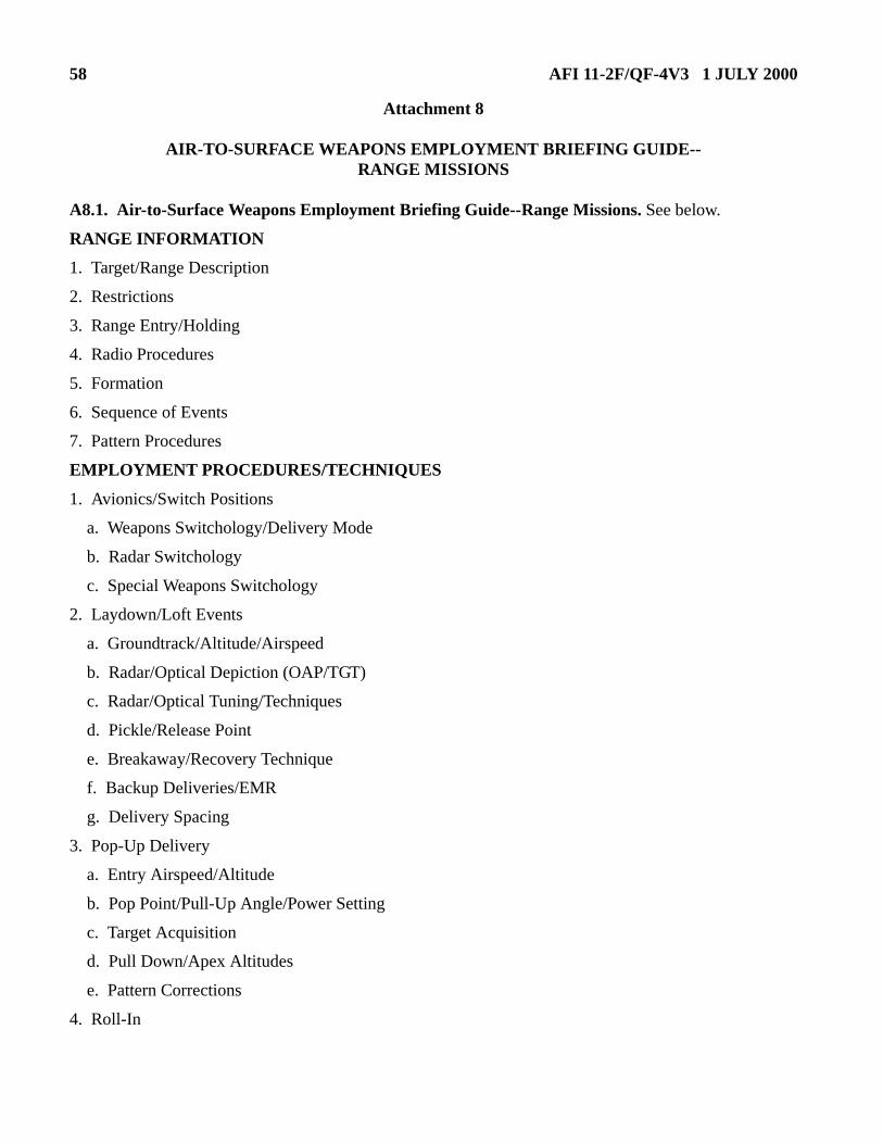
58 AFI 11-2F/QF-4V3 1 JULY 2000
Attachment 8
AIR-TO-SURFACE WEAPONS EMPLOYMENT BRIEFING GUIDE--RANGE MISSIONS
A8.1. Air-to-Surface Weapons Employment Briefing Guide--Range Missions. See below.
RANGE INFORMATION
1. Target/Range Description
2. Restrictions
3. Range Entry/Holding
4. Radio Procedures
5. Formation
6. Sequence of Events
7. Pattern Procedures
EMPLOYMENT PROCEDURES/TECHNIQUES
1. Avionics/Switch Positions
a. Weapons Switchology/Delivery Mode
b. Radar Switchology
c. Special Weapons Switchology
2. Laydown/Loft Events
a. Groundtrack/Altitude/Airspeed
b. Radar/Optical Depiction (OAP/TGT)
c. Radar/Optical Tuning/Techniques
d. Pickle/Release Point
e. Breakaway/Recovery Technique
f. Backup Deliveries/EMR
g. Delivery Spacing
3. Pop-Up Delivery
a. Entry Airspeed/Altitude
b. Pop Point/Pull-Up Angle/Power Setting
c. Target Acquisition
d. Pull Down/Apex Altitudes
e. Pattern Corrections
4. Roll-In

AFI 11-2F/QF-4V3 1 JULY 2000 59
a. Position
b. Techniques (Pitch/Bank/Power)
c. Roll-Out/Wind Effect
5. Final
a. Aim-Off Distance
b. Dive Angle
c. Airspeed
d. HUD Depiction
e. Sight Picture/Corrections/Aim-Point
f. Release Parameters
g. Release Indications
h. Recovery Procedures
SPECIAL PROCEDURES
1. Live Ordnance Considerations
a. Safe Escape/Safe Separation
b. Fuse Arming/Frag Avoidance
2. RBS Operations
NIGHT PROCEDURES
1. Aircraft Lighting
2. Radio Calls
3. Target ID/Range Lighting
4. Night Spacing Techniques
5. Instrument Crosscheck/Disorientation
6. Flare Pattern
a. Flare Release Points and Interval
b. Wind Effect/Offset
c. Dud Flare Procedures
d. Switching Aircraft Patterns
OVER WATER RANGE OPERATIONS
1. Employment Techniques
a. Depth Perception/Reduced Visual Cues
b. Distance/Altitude Estimation

60 AFI 11-2F/QF-4V3 1 JULY 2000
c. Pop-Up Positioning
(1) Timing
(2) Visual/Aircraft References to Establish Pull-Up Point
2. Special Considerations
a. Adjusted Minimum Altitudes
b. Training Rules/Special Operating Procedures
RANGE DEPARTURE PROCEDURES
1. Armament Safety Checks
2. Rejoin
3. Battle Damage/Bomb Check
4. Jettison Procedures/Parameters
5. Hung/Unexpended Ordnance
6. Inadvertent Release
7. Gun Unsafe/Jam
TRAINING RULES/SPECIAL OPERATIONS INSTRUCTIONS ALTERNATE MISSION
1. Type Mission (refer to appropriate mission briefing guide)
2. Mission Objectives
SPECIAL SUBJECTS
1. Error Analysis
2. Fouls
3. Minimum Altitudes
4. Target Fixation
5. "G" Awareness
6. Fuel Awareness/Ops Checks/AB Use/Consumption Rates
7. Maneuvering Limitations
a. Airspeed/"G"/Stress (Carriage/Release)
b. Recognition/Prevention/Recovery From Adverse Yaw Accelerated Stalls, and Loss of Control
c. Maneuvering at Heavy Weight/High Angles of Attack
d. Effects of CG Throughout the Flight
8. Time to Ground Impact
a. Wings Level
b. Overbank/Under "G"

AFI 11-2F/QF-4V3 1 JULY 2000 61
9. Hazards Associated with Human Factors (i.e., Channelized Attention, Task Saturation/Prioritization, and Complacency)

62 AFI 11-2F/QF-4V3 1 JULY 2000
Attachment 9
AIR-TO-SURFACE WEAPONS EMPLOYMENT BRIEFING GUIDE--SURFACE ATTACK TACTICS
A9.1. Air-to-Surface Weapons Employment Briefing Guide--Surface Attack Tactics. See below.
GENERAL MISSION DATA
1. Intelligence/Threat Scenario
2. Low Level (See Low Level Briefing Guide)
3. Fence Checks
4. Operating Area Entry/Description/Boundaries
5. Target Area/Clearing Pass
a. Location/Description/Elevation/TOT
b. Visual Cues in the Target Area
c. Target Area Weather
(1) Ceiling/Visibility
(2) Winds/Altimeter
(3) Sun Angle/Shadows
(4) IR Considerations
6. Threat Array
a. Type/Capabilities
b. Locations
c. Countermeasures
(1) Chaff/Flare
(2) Terrain masking
(3) Radio Silent Procedures
d. Threat Reactions
(1) LOWAT
(2) IP to Action Point
(3) During Delivery
7. Ordnance/Weapons Data
a. Type/Fuzing
b. Weapons Settings
c. Desired Effects

AFI 11-2F/QF-4V3 1 JULY 2000 63
d. Specific Aim Points
e. Minimum Altitudes
(1) Safe Escape/Safe Separation
(2) Fuze Arming/Frag Avoidance
8. Laser Operations
EMPLOYMENT PROCEDURES
1. Tactics
a. Overview
b. Ingress
(1) Formation
(2) Speed/Altitude
c. Weapons Delivery
(1) Type Delivery
(2) Switchology
(3) Attack Parameters
(a) Action Point/Pop Point
(b) Altitudes (Pull-Down/Apex/Release/Minimum)
(c) Visual Lookout/Mutual Support Responsibilities
d. Egress
(1) Recovery/Return to Low Altitude
(2) Loss of Mutual Support/Rendezvous Point
RANGE DEPARTURE PROCEDURES
1. Armament Safety Checks
2. Rejoin
3. Battle Damage/Bomb Check
4. Jettison Procedures/Parameters
5. Hung/Unexpended Ordnance
6. Inadvertent Release
7. Gun Unsafe/Jam
MISSION REPORTING (BDA/IN-FLIGHT REPORT)
CONTINGENCIES
1. Two/Three Ship Options

64 AFI 11-2F/QF-4V3 1 JULY 2000
2. Tactical Lead Changes
3. Air-to-Air TACAN
4. Codewords
5. Weather Backup Deliveries
6. Degraded Systems
7. Reattack
8. Wounded Bird/Escort Procedures
NIGHT PROCEDURES
1. Aircraft Lighting
2. Radio Calls
3. Target ID/Range Lighting
4. Night Spacing Techniques
5. Instrument Crosscheck/Disorientation
6. Flare Pattern
a. Flare Release Points and Interval
b. Wind Effect/Offset
c. Dud Flare Procedures
d. Switching Aircraft Patterns
TRAINING RULES/SPECIAL OPERATING INSTRUCTIONS
ALTERNATE MISSION
1. Type Mission (refer to appropriate mission briefing guide)
2. Mission Objectives
SPECIAL SUBJECTS
1. Error Analysis
2. Fouls
3. Minimum Altitudes
4. Target Fixation
5. "G" Awareness
6. Fuel Awareness/Ops Checks/AB Use/Consumption Rates
7. Maneuvering Limitations
a. Airspeed/"G"/Stress (Carriage/Release)
b. Recognition/Prevention/Recovery From Adverse Yaw Accelerated Stalls, and Loss of Control
AFI 11-2F/QF-4V3 1 JULY 2000 65
c. Maneuvering at Heavy Weight/High Angles of Attack Asymmetrical Configuration/In the Transonic Region
d. Effects of CG Throughout the Flight
8. Time to Ground Impact
a. Wings Level
b. Overbank/Under "G"
9. Hazards Associated with Human Factors (i. e., Channelized Attention, Task Saturation/Prioritization, and Complacency)

66 AFI 11-2F/QF-4V3 1 JULY 2000
Attachment 10
CREW COORDINATION/PASSENGER/GROUND CREW BRIEFING GUIDE
A10.1. Crew Coordination/Passenger/Ground Crew Briefing Guide. See below.
CREW COORDINATION/PASSENGER
1. Pre-Flight
2. Prohibited Items
3. Cockpit Layout
4. Flight Maneuvering Parameters
5. Mission Duties
6. Change of Aircraft Control
7. WSO Flying Parameters
8. Rear Seat Landing Procedures
9. Emergencies
a. Runway Departure
b. Canopy Loss
c. Ejection/Egress (With and Without Intercom)/Command Selector Valve Position
d. Loss of Intercom
e. Bird Strike Procedures/Use of Visor(s)
GROUND CREW
1. Act only on pilot’s instructions
2. Ground emergency procedures
3. Hand signals
4. Aircraft danger areas

AFI 11-2F/QF-4V3 1 JULY 2000 67
Attachment 11
MISSION DEBRIEFING GUIDE
A11.1. Mission Debriefing Guide. See below.
GROUND PROCEDURES
TAKEOFF/JOINUP/DEPARTURE
ENROUTE PROCEDURES
RECOVERY/LANDING/AFTER LANDING
GENERAL
1. Special Interest Items (SIIs)
2. Radio Procedures
3. Flight Discipline/Effectiveness
MISSION ACCOMPLISHMENT/ANALYSIS
1. Mission Reconstruction
2. Mission Support
3. CAVR/Film Assessment
4. Anti-G Straining Maneuver Effectiveness
5. Learning Objectives Achieved
6. Lessons Learned
7. Recommendations for Improvement
COMMENTS/QUESTIONS