by carlisle brass · 2015-12-17 · eurospec door control collection by carlisle brass. carlisle...
TRANSCRIPT

DOOR CONTROL COLLECTION 2013By Carlisle Brass
The Home of Quality Architectural Ironmongery

Eurospec Door Control Collection by Carlisle Brass
Carlisle Brass is an ISO 14001:2004 and ISO 9001:2008 accredited company.
High Performance Door Controls Extreme Performance Door Controls
Welcome to the Eurospec door control collection brochure. Our comprehensive, fully tested range of door closers are suitable for a wide variety of private, commercial and public sector applications.
Standard arm, high efficiency, cam action, electromagnetic and various concealed closers.
Next day delivery on orders placed before 5:30pm.
A fast and efficient call centre where 98% of sales calls are answered in under 40 seconds.
Carlisle Brass has full traceability of all its product lines from point of manufacture to customer, through its quality management systems.
We offer...

1
Contents
DCF2003
DCT2024
DCS2024
6
7
8
9
10
DCS2025
DCS2026
13DCC2024SM
14DCC2003SM
15DCC2024SM/36
16DCC2024CF
17DCC2003CF
18DCC2024CF/36
20DCFS150/EN3DCFS250/EN4
21DCTS100/EN3DCTS150/EN4
22H2N1900H2N1950
24DCCEM3024
25DCEM2003
26DCEM2004
29AA45, CDC85SC/RCDG003

2
Key to Finishes and Symbols
Finishes
BSS
CP
EB
EBP
PB
Bright Stainless Steel
Polished Chrome
Electro Brass
Electro Brass Plate
Polished Brass
PC
PNP
Polished Chrome
Polished Nickel Plate
PVD
SNP
SC
Stainless Brass
Satin Chrome
Satin Nickel Plate
SSS
SV
WHT
Satin Stainless Steel
Silver
White
Suitable Environments for Use
Housing/Domestic Office/RetailCommercial
Hospitals/Government Education Sports Stadia/Institution
Symbols
APPROVED PRODUCT
FD30 FD120/240
BS EN 1634 PART1:2000 European Fire Safety standard for determining the fire resistance of door and shutter assemblies, including door hardware. FD30 (30 Minute Fire Doors) FD60 (60 Minute Fire Doors) FD120 (120 Minute Fire Doors)FD120 (120 Minute Metal Fire Doors) FD240 (240 Minute Metal Fire Doors).The UK Construction Products Directive requires that door hardware for use on fire doors be safe and durable. It is recommended that door hardware fitted to fire doors should be CE marked.
Certifire is an independent 3rd party scheme providing high quality, voluntary, product conformity for the passive fire sector. The requirements are based on those of CE marking, but whereas the CE mark reflects compliance with minimum regulatory requirements Certifire is product certification at a higher level. Additional requirements are ISO9001:2008 certification, independent audit testing and a comprehensive field of application document based on carefully chosen tests. Designed to give confidence to specifiers, enforcement authorities and building owners/occupiers, the Certifire scheme is recognised by regulatory authorities both in the UK and overseas.
10 Year Mechanical Guarantee
G
UARANTEE
MECHANICA
L
yr
2 Year Electrical Guarantee
G
UARANTEE
MECHANICA
L
yr 2 Year Mechanical Guarantee
CE Marking is certification to the highest levels of attestation required by the Construction Products Directive. The CE mark indicates that the product has been successfully 3rd party performance/fire tested and that the producing factory has passed stringent Factory Production Control audits, carried out by a UKAS notified certification body.
BS EN 1154
British/European standard requirements and testing methods covering controlled door closing devices.
BS EN 1155
British/European standard requirements and testing methods covering electrically powered hold open devices for swing doors.
FD30/60 FD60 FD30/60/120 BS 8300 is the design of buildings and their approaches to meet the needs of disabled people. NOTE: BS 8300 Requirements are for the
whole door set and therefore the
minimum width of suitable door will
increase when the door is fitted with all
other items of ironmongery on site.
G
UARANTEE
yr
EC ICAL
RT
EL

3
BS EN 1154:1996 Explained...
BS EN 1154:1996 is the European standard for controlled door closing devices and, as such, tests mechanical door closer performance.Adopted by EU member states, it became a mandatory requirement for CE marking in 2004. It prescribes the test methodology and subsequent classification of randomly selected production line products. The test data, together with supporting technical evaluation, results in a classification code.This coding allows comparison across a range of closers according to their compliance with the standard.
Door closers for fire doors are covered by a Constructive Products Directive mandate. Compliance with BS EN 1154:1996, supported by suitable evidence, therefore allows the application of the CE mark. All conforming door closers consequently will be marked with their BS EN 1154:1996 coding and details of the notified certification body.
Door controls with electrical components, such as electromagnetic hold open devices, must also satisfy the requirements of both BS EN 1154:1996 and the supplementary standard, BS EN 1155:1997 for electrically controlled door operators.
4 8 3 1 1 3
Category of UseDefines the angle from which the closer will close the door in a controlled manner. Grade 3 will control the door from 105°. Most Carlisle Brass closers will operate from 180° - Grade 4.
Test CyclesIncluded in a 500,000 cycle test as defined by Grade 8 the only grade available.
Door Size/MassThe number identifies the power size of the closer as defined by the door size and mass. Adjustable power closers are defined by the upper and lower power sizes.
Closer Size Max Door Size
1 750mm - 20Kg2 850mm - 40Kg3 950mm - 60Kg4 1100mm - 80Kg5 1250mm - 100Kg6 1400mm - 120Kg7 1600mm - 160Kg
Corrosion ResistanceA salt spray test is used to ascertain corrosion resistance thereby establishing suitability for use in varying environmental conditions. Five grades are identified from 0 (no identified resistance) to 4 (very high resistance). All Carlisle Brass closers achieve at least Grade 3 and are suitable for use in wet, polluted environments and most exterior applications.
Fire BehaviourBased on the results of fire testing to BS EN 1634 ensuring the door remains closed under temperatures which can exceed 1000°C. Grade 1 is for closers which are deemed suitable for use on fire doors. Grade 0 are not suitable for use on fire doors.
SafetyThe part of the standard which ensures the operation and suitability of the closer is hazard free. It provides peace of mind that the closer operates without risk to the user. Only Grade 1 is identified.

4
Select the Correct Door Closer For Your Application
Which Door Closer?
Entry Closers forGeneral Applications
Medium FrequencyCommercial Applications
High FrequencyCommercial Applications
DCF2003SV
CDG003
AA45
Fixed Range
Jamb Mounted Range
CDC85SC/R
Variable Position Template Range
DCT2024
Variable Position Spring Range
DCS2024-2026
High Efficiency Slide ChannelConcealed and Surface
Mounted Range
DCC2003CF-DCC2024SM
Electromagnetic Range
DCEM2003-DCEM3024
Floor Springs Range
DCFS150/EN3-DCFS250/EN4
DCF2003SV
DCS2024-2026
DCC2003CF-DCC2024SM
Transom Closers Range
DCTS100/EN3-DCTS150/EN4

5

DCF2003Overhead Door Closer Fixed Power Size 3
64
BSS DCF2003BSS/FCP
EBP DCF2003EBP/FCP
PNP DCF2003PNP/FCP
PVD DCF2003PVD/FCP
SNP DCF2003SNP/FCP
SSS DCF2003SSS/FCP
SV DCF2003SV/FCP
Specification Cover Packs Finishes Suitable Environments
6
G
UARANTEE
MECHANICA
L
yr
APPROVED PRODUCTCF646
BS EN 1154
FD30/60/120
17
52
63
3042
178
180
Max Closing Moment (EN)Opening Moment
The DCF2003 overhead door closer has an opening force (0-30°) less than 30N when fitted to a minimum width door of 926mm, and has an opening force (30-60°) less than 22.5N when fitted to a minimum width door of 838mm tested in laboratory conditions. Therefore the suitable width of door for the DCF2003 overhead door closer fixed in the above fixing position is 926mm.
Torq
ue (N
m)
Door Angle (°)
10
20
30
40
50
0 906030 120 150
Closing MomentMin Closing Moment (EN)
Efficiency %: 70Max Opening 0°- 4° (Nm): 29.26Max Opening 0°- 60° (Nm): 29.63Max Closing 4° - 0° (Nm): 20.58Max Closing 92° - 88° (Nm): 11.64
BS EN 1154:1996 - Fig 1 Fitting
4 8 1 1 33
1121-CPD-AD0196
BS EN 1154:1996 - Fig 6 Fitting
4 8 1 1 33
1121-CPD-AD0196
EBP
SNP
BSS
PVD
SSS
SV
PNP
Closing Force EN Size 3
Efficiency 70%
Max Door Width 950mm
Max Weight 60Kg
Angle of Opening Max 180°
Suitable for LH/RH Use
Easi Fix Template Supplied
Adjustable Closing Speed
Adjustable Latching Speed
10 Year Mechanical Guarantee
Accessory Packs Available

DCT2024Overhead Door Closer Variable Power Size 2-4
Specification Cover Packs Finishes Suitable Environments
The Home of Quality Architectural Ironmongery
7
G
UARANTEE
MECHANICA
L
yr
BS EN 1154
FD30/60/120
DCT2024SVBSS DCT2024BSS/FCPEBP DCT2024EBP/FCPPNP DCT2024PNP/FCPPVD DCT2024PVD/FCPSNP DCT2024SNP/FCPSSS DCT2024SSS/FCPSV DCT2024SV/FCP
DCT2024BC/SV & PB*BSS DCT2024BC/BSS/FCPEBP DCT2024BC/EBP/FCPPNP DCT2024BC/PNP/FCPPVD DCT2024BC/PVD/FCPSNP DCT2024BC/SNP/FCPSSS DCT2024BC/SSS/FCPSV DCT2024BC/SV/FCP
40207
55
40Max Closing Moment (EN)Opening MomentClosing MomentMin Closing Moment (EN)
180
Max Closing Moment (EN)Opening Moment
The DCT2024 & DCT2024BC overhead door closer has an opening force (0-30°) less than 31N when fitted to a minimum width door of 948mm, and has an opening force (30-60°) less than 22.5N when fitted to a minimum width door of 838mm tested in laboratory conditions. Therefore the suitable width of door for the DCT2024 & DCT2024BC overhead door closer fixed in the above fixing position is 948mm.
Torq
ue (N
m)
Door Angle (°)
10
20
30
40
50
0 906030 120 150
Closing MomentMin Closing Moment (EN)
Efficiency %: 60%Max Opening 0°- 4° (Nm): 30.37Max Opening 0°- 60° (Nm): 30.37Max Closing 4° - 0° (Nm): 18.25Max Closing 92° - 88° (Nm): 10.17
65 78
BS EN 1154:1996 - Fig 1 Fitting
4 8 1 1 3
1121-CPD-AD0197
BS EN 1154:1996 - Fig 6 Fitting
4 8 1 1 33
1121-CPD-AD0197
42
APPROVED PRODUCTCF646
EBP
SNP
BSS
PVD
SSS
SV
PNP
Closing Force EN Size 2-4
Efficiency 60%
Max Door Width 1100mm
Max Weight 80Kg
Angle of Opening Max 180°
Suitable for LH/RH Use
Easi Fix Template Supplied
Adjustable Closing Speed
Adjustable Latching Speed
10 Year Mechanical Guarantee
Accessory Packs Available
Optional Backcheck DCT2024BC
*Backcheck not covered by CE or Certifire.

DCS2024BCOverhead Door Closer Variable Power Size 2-4
Specification Cover Packs Finishes Suitable Environments
8
G
UARANTEE
MECHANICA
L
yr
APPROVED PRODUCTCF646
BS EN 1154
FD30/60/120
39
39
60
236
180
Max Closing Moment (EN)Opening Moment
The DCS2024BC overhead door closer has an opening force (0-30°) less than 30N when fitted to a minimum width door of 926mm, and has an opening force (30-60°) less than 22.5N when fitted to a minimum width door of 838mm tested in laboratory conditions. Therefore the suitable width of door for the DCS2024BC overhead door closer fixed in the above fixing position is 926mm.
Torq
ue (N
m)
Door Angle (°)
10
20
30
40
50
0 906030 120 150
Closing MomentMin Closing Moment (EN)
Efficiency %: 70Max Opening 0°- 4° (Nm): 29.26Max Opening 0°- 60° (Nm): 29.63Max Closing 4° - 0° (Nm): 20.58Max Closing 92° - 88° (Nm): 11.64
78
BS EN 1154:1996 - Fig 1 Fitting
4 8 1 1 3
1121-CPD-AD0198
BS EN 1154:1996 - Fig 6 Fitting
4 8 1 1 3
1121-CPD-AD0198
42
42
BSS DCS2024BC/BSS/FCP
EBP DCS2024BC/EBP/FCP
PNP DCS2024BC/PNP/FCP
PVD DCS2024BC/PVD/FCP
SNP DCS2024BC/SNP/FCP
SSS DCS2024BC/SSS/FCP
SV DCS2024BC/SV/FCP
EBP
SNP
BSS
PVD
SSS
SV
PNP
Closing Force EN Size 2-4 Efficiency 70% Max Door Width 1100mm Max Weight 80Kg Angle of Opening Max 180° Suitable for LH/RH Use Power Adjustment by Spring Adjustable Closing Speed Adjustable Latching Speed 10 Year Mechanical Guarantee Accessory Packs Available Backcheck Meets recommendations of BS 8300 and Approved Document M

DCS2025BC Overhead Door Closer Variable Power Size 2-5
Specification Cover Packs Finishes Suitable Environments
The Home of Quality Architectural Ironmongery
9
G
UARANTEE
MECHANICA
L
yr
APPROVED PRODUCTCF646
BS EN 1154
FD30/60/120
39
60
236
Max Closing Moment (EN)Opening MomentClosing MomentMin Closing Moment (EN)
180
Max Closing Moment (EN)Opening Moment
The DCS2025BC overhead door closer has an opening force (0-30°) less than 30N when fitted to a minimum width door of 926mm, and has an opening force (30-60°) less than 22.5N when fitted to a minimum width door of 838mm tested in laboratory conditions. Therefore the suitable width of door for the DCS2025BC overhead door closer fixed in the above fixing position is 926mm.
Torq
ue (N
m)
Door Angle (°)
10
20
30
40
50
0 906030 120 150
Closing MomentMin Closing Moment (EN)
Efficiency %: 67Max Opening 0°- 4° (Nm): 29.16Max Opening 0°- 30° (Nm): 29.16Max Closing 30° - 60° (Nm): 20.15Max Closing 4° - 0° (Nm): 19.42
39
78
BS EN 1154:1996 - Fig 1 Fitting
4 8 1 1 3
1121-CPD-AD0199
BS EN 1154:1996 - Fig 6 Fitting
4 8 1 1 3
1121-CPD-AD0199
52
42
*Delayed Action not covered by CE or Certifire.
DCS2025BCBSS DCS2025BC/BSS/FCPEBP DCS2025BC/EBP/FCPPNP DCS2025BC/PNP/FCPPVD DCS2025BC/PVD/FCPSNP DCS2025BC/SNP/FCPSSS DCS2025BC/SSS/FCPSV DCS2025BC/SV/FCP
DCS2025BCDA*BSS DCS2025BCDA/BSS/FCPEBP DCS2025BCDA/EBP/FCPPNP DCS2025BCDA/PNP/FCPPVD DCS2025BCDA/PVD/FCPSNP DCS2025BCDA/SNP/FCPSSS DCS2025BCDA/SSS/FCPSV DCS2025BCDA/SV/FCP
EBP
SNP
BSS
PVD
SSS
SV
PNP
Closing Force EN Size 2-5 Efficiency 67% Max Door Width 1250mm Max Weight 100Kg Angle of Opening Max 180° Suitable for LH/RH Use Power Adjustment by Spring Adjustable Closing Speed Adjustable Latching Speed 10 Year Mechanical Guarantee Accessory Packs Available Backcheck Optional Delayed Action DCS2025BCDA Meets recommendations of BS 8300 and Approved Document M

DCS2026BCOverhead Door Closer Variable Power Size 2-6
Specification Cover Packs Finishes Suitable Environments
10
G
UARANTEE
MECHANICA
L
yr
APPROVED PRODUCTCF646
BS EN 1154
FD30/60/120
45
62
27545
BSS
PVD
SSS
SV
DCS2026BC
BSS DCS2026BC/BSS/FCP
PVD DCS2026BC/PVD/FCP
SSS DCS2026BC/SSS/FCP
SV DCS2026BC/SV/FCP
DCS2026BCDA*
BSS DCS2026BCDA/BSS/FCP
PVD DCS2026BCDA/PVD/FCP
SSS DCS2026BCDA/SSS/FCP
SV DCS2026BCDA/SV/FCP
80
180
Max Closing Moment (EN)Opening Moment
The DCS2026BC overhead door closer has an opening force (0-30°) less than 33N when fitted to a minimum width door of 1030mm, and has an opening force (30-60°) less than 22.5N when fitted to a minimum width door of 926mm tested in laboratory conditions. Therefore the suitable width of door for the DCS2026BC overhead door closer fixed in the above fixing position is 1030mm. (Power trace taken at 0 cycles).
Torq
ue (N
m)
Door Angle (°)
10
20
30
40
50
0 906030 120 150
Closing MomentMin Closing Moment (EN)
Efficiency %: 76.9Max Opening 0°- 4° (Nm): 32.2Max Opening 0°- 30° (Nm): 32.2Max Closing 30° - 60° (Nm): 29.7Max Closing 4° - 0° (Nm): 24.8
BS EN 1154:1996 - Fig 1 Fitting
4 8 1 1 3
1121-CPD-AD0200
BS EN 1154:1996 - Fig 6 Fitting
3 8 1 1 3
1121-CPD-AD0200
62
54
*Delayed Action not covered by CE or Certifire.
Closing Force EN Size 2-6 Efficiency 76% Max Door Width 1400mm Max Weight 120Kg Angle of Opening Max 180° Suitable for LH/RH Use Power Adjustment by Spring Adjustable Closing Speed Adjustable Latching Speed 10 Year Mechanical Guarantee Accessory Packs Available Backcheck Optional Delayed Action DCS2026BCDA Meets recommendations of BS 8300 and Approved Document M
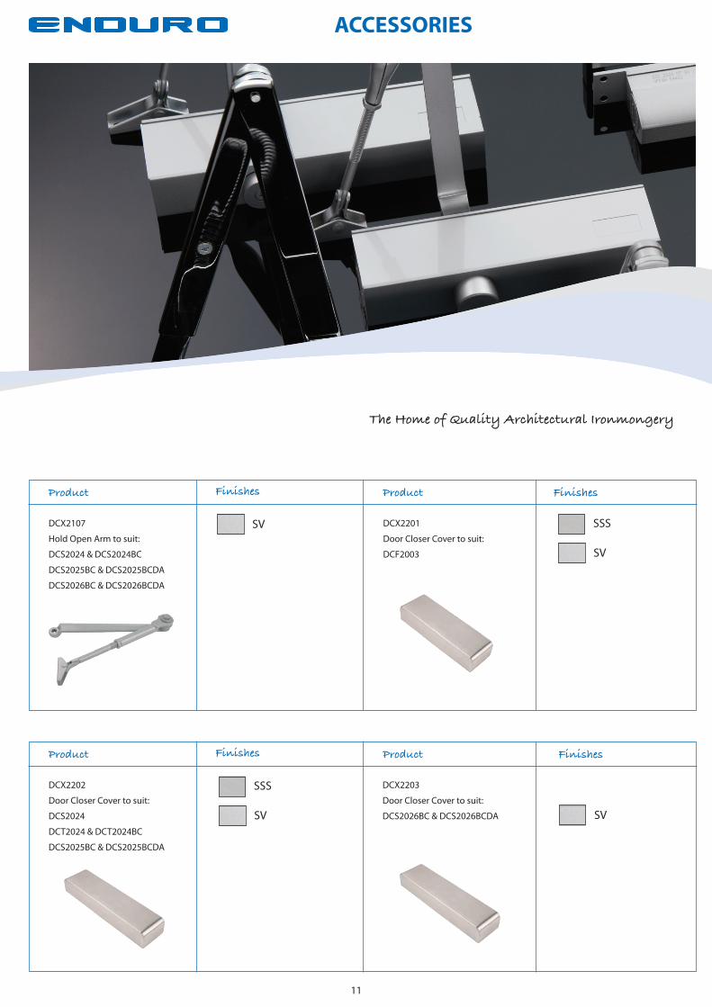
ACCESSORIES
The Home of Quality Architectural Ironmongery
11
Product Finishes Product Finishes
SV
SSSDCX2202
Door Closer Cover to suit:
DCS2024
DCT2024 & DCT2024BC
DCS2025BC & DCS2025BCDA
Product Finishes Product Finishes
SV
SV SSSDCX2107
Hold Open Arm to suit:
DCS2024 & DCS2024BC
DCS2025BC & DCS2025BCDA
DCS2026BC & DCS2026BCDA
DCX2201
Door Closer Cover to suit:
DCF2003
DCX2203
Door Closer Cover to suit:
DCS2026BC & DCS2026BCDA SV
Max Closing Moment (EN)Opening MomentClosing MomentMin Closing Moment (EN)


DCC2024SMSurface Mounted Slim H.E Door Closer Power Size 2-4
180
Max Closing Moment (EN)Opening Moment
The DCC2024SM surface mounted slim H.E door closer has an opening force (0-30°) less than 30N when fitted to a minimum width door of 747mm, and has an opening force (30-60°) less than 22.5N when fitted to a minimum width door of 542mm tested in laboratory conditions. Therefore the suitable width of door for the DCC2024SM surface mounted slim H.E door closer fixed in the above fixing position is 747mm.
Torq
ue (N
m)
Door Angle (°)
10
20
30
40
50
0 906030 120 150
Closing MomentMin Closing Moment (EN)
Efficiency %: 80.1Max Opening 0°- 30° (Nm): 22.4Max Opening 30°- 60° (Nm): 12.2Max Closing 4° - 0° (Nm): 18.0
1121 - CPD - AD5036
EN 1154:1996 + A1:2002 + AC:2006
12
3 8 4 1 1 32
Specification Cover Packs Finishes Suitable Environments
The Home of Quality Architectural Ironmongery
13
G
UARANTEE
MECHANICA
L
yr
APPROVED PRODUCTCF5087
BS EN 1154
FD30/60/120
FD120/240
BSS DCP3000/BSS
EBP DCP3000/EBP
PNP DCP3000/PNP
PVD DCP3000/PVD
SNP DCP3000/SNP
SSS DCP3000/SSS
32
54
21532
(SV = Cover Only)
EBP
SNP
BSS
PVD
SSS
SV
PNP
Closing Force EN Size 2-4 Efficiency 80% Max Door Width 1100mm Max Weight 80Kg Angle of Opening Max 120° Suitable for LH/RH Use Power Adjustment by Spring Adjustable Closing Speed Adjustable Latching Speed 10 Year Mechanical Guarantee Accessory Packs Available Slide Channel Slimline Body Meets recommendations of BS 8300 and Approved Document M

DCC2003SMSurface Mounted Slim Door Closer Fixed Power Size 3
Specification Cover Packs Finishes Suitable Environments
1121 - CPD - AD5036
EN 1154:1996 + A1:2002 + AC:2006
12
3 8 1 1 33
14
G
UARANTEE
MECHANICA
L
yr
APPROVED PRODUCTCF5087
BS EN 1154
FD30/60/120
FD120/240
36
59
23636
180
Max Closing Moment (EN)Opening Moment
The DCC2003SM surface mounted H.E door closer has an opening force (0-30°) less than 30N when fitted to a minimum width door of 753mm, and has an opening force (30-60°) less than 22.5N when fitted to a minimum width door of 569mm tested in laboratory conditions. Therefore the suitable width of door for the DCC2003SM surface mounted H.E door closer fixed in the above fixing position is 753mm. (Power trace taken at 0 cycles).
Torq
ue (N
m)
Door Angle (°)
10
20
30
40
50
0 906030 120 150
Closing MomentMin Closing Moment (EN)
Efficiency %: 77.9Max Opening 0°- 4° (Nm): 28.3Max Opening 0°- 60° (Nm): 28.3Max Closing 4° - 0° (Nm): 22.0
BSS DCP3202/BSS
EBP DCP3202/EBP
PNP DCP3202/PNP
PVD DCP3202/PVD
SNP DCP3202/SNP
SSS DCP3202/SSS
SV DCP3202/SV
EBP
SNP
BSS
PVD
SSS
SV
PNP
Closing Force EN Size 3 Efficiency 77% Max Door Width 950mm Max Weight 60Kg Angle of Opening Max 120° Suitable for LH/RH Use Adjustable Closing Speed Adjustable Latching Speed 10 Year Mechanical Guarantee Accessory Packs Available Slide Channel Slimline Body Meets recommendations of BS 8300 and Approved Document M
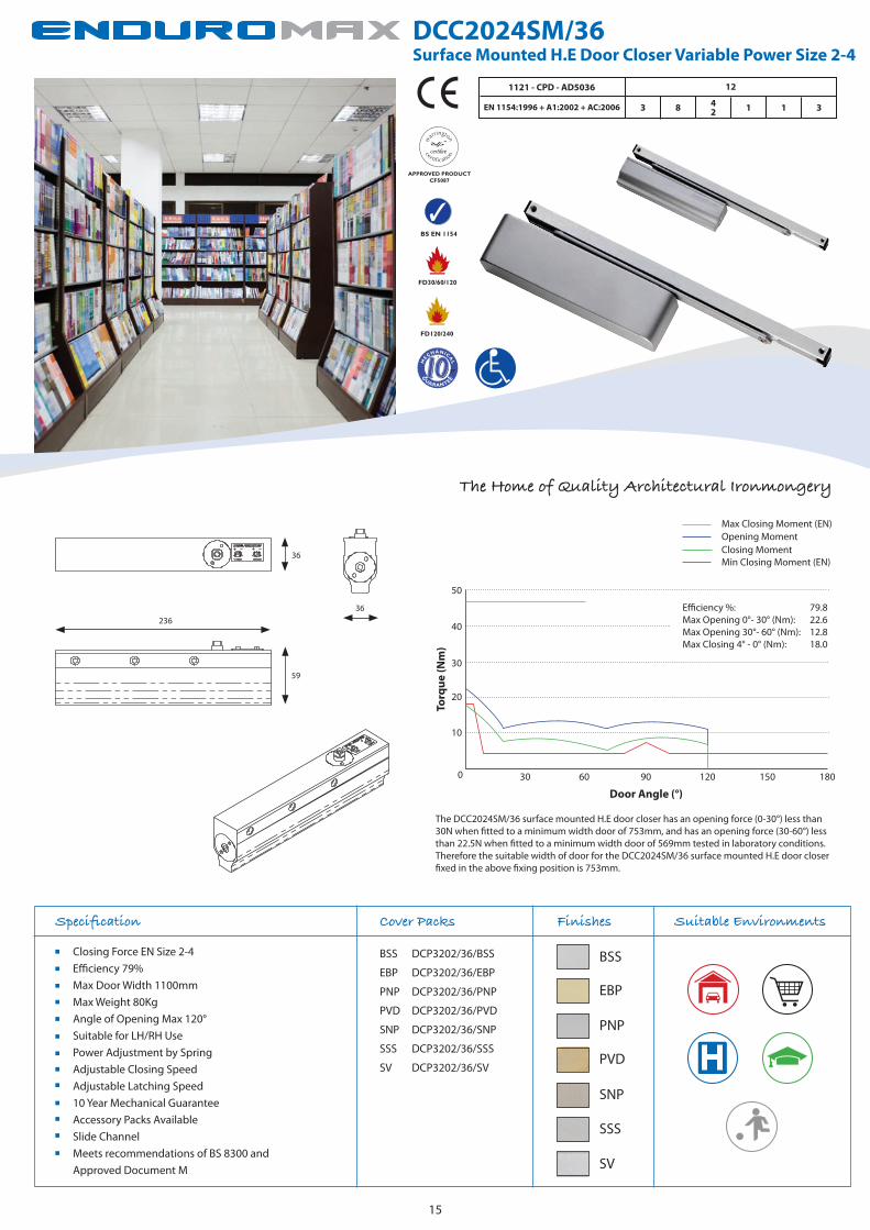
DCC2024SM/36Surface Mounted H.E Door Closer Variable Power Size 2-4
1121 - CPD - AD5036
EN 1154:1996 + A1:2002 + AC:2006
12
3 8 4 1 1 32
Specification Cover Packs Finishes Suitable Environments
The Home of Quality Architectural Ironmongery
15
G
UARANTEE
MECHANICA
L
yr
APPROVED PRODUCTCF5087
BS EN 1154
FD30/60/120
FD120/240
180
Max Closing Moment (EN)Opening Moment
The DCC2024SM/36 surface mounted H.E door closer has an opening force (0-30°) less than 30N when fitted to a minimum width door of 753mm, and has an opening force (30-60°) less than 22.5N when fitted to a minimum width door of 569mm tested in laboratory conditions. Therefore the suitable width of door for the DCC2024SM/36 surface mounted H.E door closer fixed in the above fixing position is 753mm.
Torq
ue (N
m)
Door Angle (°)
10
20
30
40
50
0 906030 120 150
Closing MomentMin Closing Moment (EN)
Efficiency %: 79.8Max Opening 0°- 30° (Nm): 22.6Max Opening 30°- 60° (Nm): 12.8Max Closing 4° - 0° (Nm): 18.0
36
59
23636
Max Closing Moment (EN)Opening MomentClosing MomentMin Closing Moment (EN)
EBP
SNP
BSS
PVD
SSS
SV
PNP
BSS DCP3202/36/BSS
EBP DCP3202/36/EBP
PNP DCP3202/36/PNP
PVD DCP3202/36/PVD
SNP DCP3202/36/SNP
SSS DCP3202/36/SSS
SV DCP3202/36/SV
Closing Force EN Size 2-4 Efficiency 79% Max Door Width 1100mm Max Weight 80Kg Angle of Opening Max 120° Suitable for LH/RH Use Power Adjustment by Spring Adjustable Closing Speed Adjustable Latching Speed 10 Year Mechanical Guarantee Accessory Packs Available Slide Channel Meets recommendations of BS 8300 and Approved Document M

DCC2024CFConcealed Slim Door Closer Variable Power Size 2-4
180
Max Closing Moment (EN)Opening Moment
The DCC2024CF concealed door closer has an opening force (0-30°) less than 30N when fitted to a minimum width door of 760mm, and has an opening force (30-60°) less than 22.5N when fitted to a minimum width door of 600mm tested in laboratory conditions. Therefore the suitable width of door for the DCC2024CF concealed door closer fixed in the above fixing position is 760mm.
Torq
ue (N
m)
Door Angle (°)
10
20
30
40
50
0 906030 120 150
Closing MomentMin Closing Moment (EN)
Efficiency %: 79.8Max Opening 0°- 30° (Nm): 22.8Max Opening 30°- 60° (Nm): 13.5Max Closing 4° - 0° (Nm): 18.2
215
Specification Accessories Finishes Suitable Environments
1121 - CPD - AD5036
EN 1154:1996 + A1:2002 + AC:2006
12
3 8 4 1 1 32
16
G
UARANTEE
MECHANICA
L
yr
APPROVED PRODUCTCF5087
BS EN 1154
FD30/60/120
FD120/240
PNP
SNP
Arm Only
EBP DCX2002/EBP
PNP DCX2002/PNP
SNP DCX2002/SNP
Intumescent Pack
INT2024
EBP
54
32285
Closing Force EN Size 2-4 Efficiency 79% Max Door Width 1100mm Max Weight 80Kg Angle of Opening Max 120° Suitable for LH/RH Use Power Adjustment by Spring Adjustable Closing Speed Adjustable Latching Speed 10 Year Mechanical Guarantee Accessory Packs Available Slide Channel Slimline Body Meets recommendations of BS 8300 and Approved Document M

DCC2003CFConcealed Slim Door Closer Fixed Power Size 3
Max Closing Moment (EN)Opening MomentClosing MomentMin Closing Moment (EN)
1121 - CPD - AD5036
EN 1154:1996 + A1:2002 + AC:2006
12
3 8 1 1 33
Specification Accessories Finishes Suitable Environments
The Home of Quality Architectural Ironmongery
17
G
UARANTEE
MECHANICA
L
yr
APPROVED PRODUCTCF5087
BS EN 1154
FD30/60/120
FD120/240
180
Max Closing Moment (EN)Opening Moment
The DCC2003CF surface mounted H.E door closer has an opening force (0-30°) less than 33N when fitted to a minimum width door of 797mm, and has an opening force (30-60°) less than 22.5N when fitted to a minimum width door of 600mm tested in laboratory conditions. Therefore the suitable width of door for the DCC2003CF surface mounted H.E door closer fixed in the above fixing position is 797mm. (Power trace taken at 0 cycles).
Torq
ue (N
m)
Door Angle (°)
10
20
30
40
50
0 906030 120 150
Closing MomentMin Closing Moment (EN)
Efficiency %: 70.9Max Opening 0°- 4° (Nm): 33.4Max Opening 0°- 60° (Nm): 33.4Max Closing 4° - 0° (Nm): 23.7
305
235
63
36
PNP
SNP
Arm Only
EBP DCX2002/EBP
PNP DCX2002/PNP
SNP DCX2002/SNP
Intumescent Pack
INT2024/36
EBP Closing Force EN Size 3 Efficiency 70% Max Door Width 950mm Max Weight 60Kg Angle of Opening Max 120° Suitable for LH/RH Use Adjustable Closing Speed Adjustable Latching Speed 10 Year Mechanical Guarantee Accessory Packs Available Slide Channel Slimline Body Meets recommendations of BS 8300 and Approved Document M
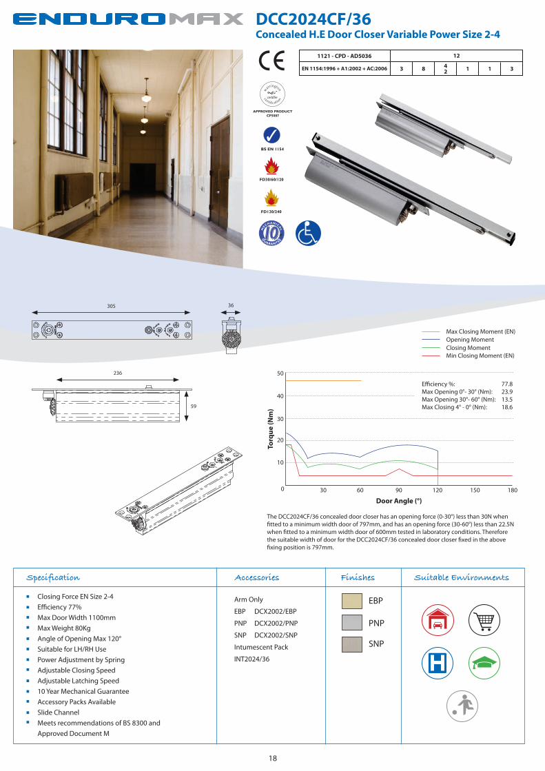
DCC2024CF/36Concealed H.E Door Closer Variable Power Size 2-4
180
Max Closing Moment (EN)Opening Moment
The DCC2024CF/36 concealed door closer has an opening force (0-30°) less than 30N when fitted to a minimum width door of 797mm, and has an opening force (30-60°) less than 22.5N when fitted to a minimum width door of 600mm tested in laboratory conditions. Therefore the suitable width of door for the DCC2024CF/36 concealed door closer fixed in the above fixing position is 797mm.
Torq
ue (N
m)
Door Angle (°)
10
20
30
40
50
0 906030 120 150
Closing MomentMin Closing Moment (EN)
Efficiency %: 77.8Max Opening 0°- 30° (Nm): 23.9Max Opening 30°- 60° (Nm): 13.5Max Closing 4° - 0° (Nm): 18.6
Specification Accessories Finishes Suitable Environments
1121 - CPD - AD5036
EN 1154:1996 + A1:2002 + AC:2006
12
3 8 4 1 1 32
18
G
UARANTEE
MECHANICA
L
yr
APPROVED PRODUCTCF5087
BS EN 1154
FD30/60/120
FD120/240
236
59
36305
PNP
SNP
Arm Only
EBP DCX2002/EBP
PNP DCX2002/PNP
SNP DCX2002/SNP
Intumescent Pack
INT2024/36
EBP Closing Force EN Size 2-4 Efficiency 77% Max Door Width 1100mm Max Weight 80Kg Angle of Opening Max 120° Suitable for LH/RH Use Power Adjustment by Spring Adjustable Closing Speed Adjustable Latching Speed 10 Year Mechanical Guarantee Accessory Packs Available Slide Channel Meets recommendations of BS 8300 and Approved Document M

ACCESSORIES
Max Closing Moment (EN)Opening MomentClosing MomentMin Closing Moment (EN)
19
The Home of Quality Architectural Ironmongery
Product Finishes Product Finishes
DCX3202/36
Door Closer Cover to suit:
DCC2024SM/36
DCC2003SM/36
Product Finishes Product Finishes
DCX2002
Plated Arm to suit:
DCC2024SM & DCC2024SM36
DCC2003SM
DCC2024CF & DCC2024CF36
DCX2003
Chanel Forend to suit:
DCC2024SM & DCC2024SM36
DCC2003SM
DCC2024CF & DCC2024CF36
DCX3202
Door Closer Cover to suit:
DCC2024SM
PNP
SNP
EBP BSS
PVD
SSS
PNP
SNP
EBP
SV
PNP
SNP
EBP
SV
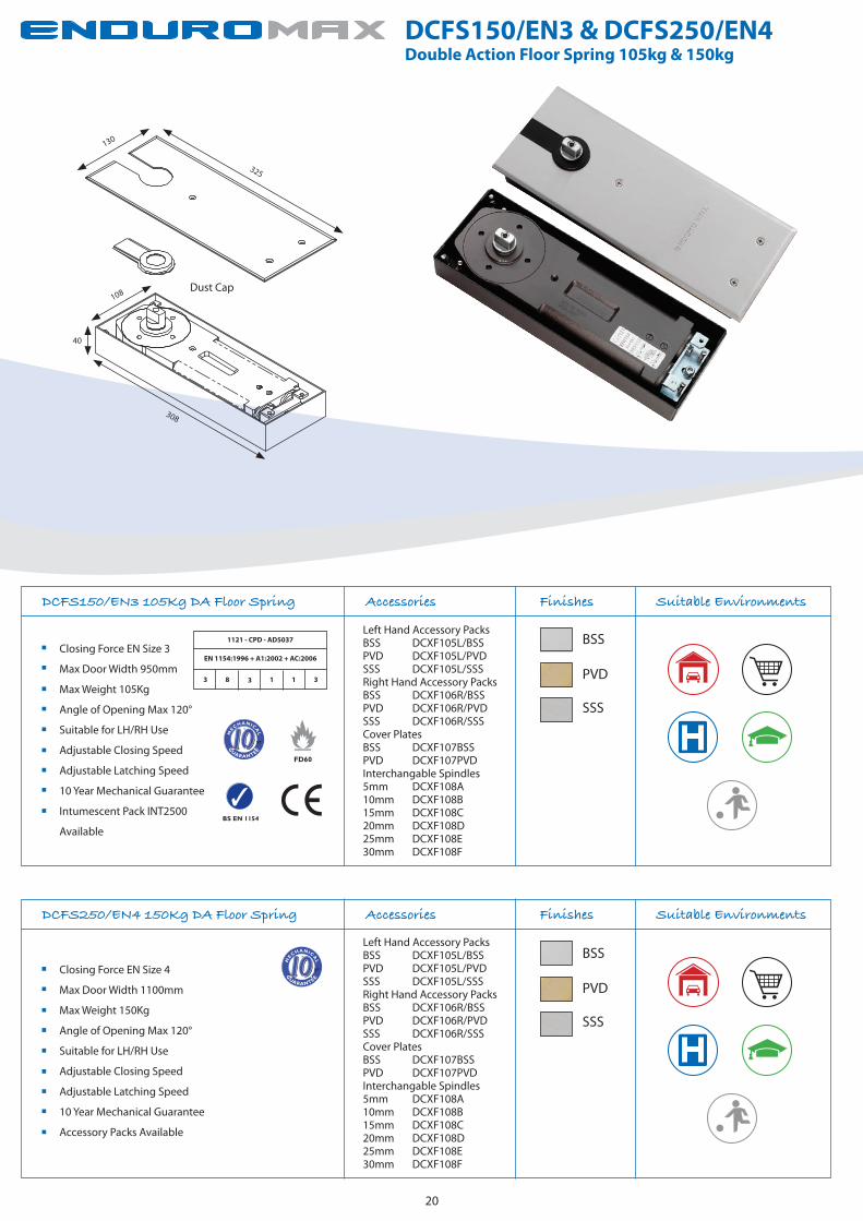
DCFS150/EN3 & DCFS250/EN4Double Action Floor Spring 105kg & 150kg
20
Closing Force EN Size 4
Max Door Width 1100mm
Max Weight 150Kg
Angle of Opening Max 120°
Suitable for LH/RH Use
Adjustable Closing Speed
Adjustable Latching Speed
10 Year Mechanical Guarantee
Accessory Packs Available
DCFS250/EN4 150Kg DA Floor Spring Accessories Finishes Suitable Environments
G
UARANTEE
MECHANICA
L
yr
BS EN 1154
FD60
DCFS150/EN3 105Kg DA Floor Spring Accessories Finishes
Closing Force EN Size 3
Max Door Width 950mm
Max Weight 105Kg
Angle of Opening Max 120°
Suitable for LH/RH Use
Adjustable Closing Speed
Adjustable Latching Speed
10 Year Mechanical Guarantee
Intumescent Pack INT2500
Available
Suitable Environments
Left Hand Accessory PacksBSS DCXF105L/BSSPVD DCXF105L/PVDSSS DCXF105L/SSSRight Hand Accessory PacksBSS DCXF106R/BSSPVD DCXF106R/PVDSSS DCXF106R/SSSCover PlatesBSS DCXF107BSSPVD DCXF107PVDInterchangable Spindles5mm DCXF108A10mm DCXF108B15mm DCXF108C20mm DCXF108D25mm DCXF108E30mm DCXF108F
BSS
PVD
SSS
Left Hand Accessory PacksBSS DCXF105L/BSSPVD DCXF105L/PVDSSS DCXF105L/SSSRight Hand Accessory PacksBSS DCXF106R/BSSPVD DCXF106R/PVDSSS DCXF106R/SSSCover PlatesBSS DCXF107BSSPVD DCXF107PVDInterchangable Spindles5mm DCXF108A10mm DCXF108B15mm DCXF108C20mm DCXF108D25mm DCXF108E30mm DCXF108F
BSS
PVD
SSS
G
UARANTEE
MECHANICA
L
yr
130
325
108
40
308
Dust Cap
1121 - CPD - AD5037
EN 1154:1996 + A1:2002 + AC:2006
3 8 3 1 1 3

DCTS100/EN3 & DCTS150/EN4Concealed NHO Transom Closer Power Size 3 & Power Size 4 with Side Load Accessories
The Home of Quality Architectural Ironmongery
21
Side Load Accessory Pack
DCXT100/SL
DCTS150/EN4 Accessories Finishes
Closing Force EN Size 4
Efficiency 63%
Max Door Width 1100mm
Max Weight 150Kg
Angle of Opening Max 130°
Suitable for LH/RH Use
Adjustable Closing Speed
Adjustable Latching Speed
2 Year Mechanical Guarantee
HO90 Mechanism Only Version Available DCTS150/EN4/HO
Suitable Environments
SV
Side Load Accessory Pack
DCXT100/SL
DCTS100/EN3 Accessories Finishes
Closing Force EN Size 3
Efficiency 63%
Max Door Width 950mm
Max Weight 105Kg
Angle of Opening Max 130°
Suitable for LH/RH Use
Adjustable Closing Speed
Adjustable Latching Speed
2 Year Mechanical Guarantee
HO90 Mechanism Only Version Available DCTS100/EN3/HO
Suitable Environments
SV
G
UARANTEE
MECHANICA
L
yr
G
UARANTEE
MECHANICA
L
yr
29338
91

H2N1900 & H2N1950 Thrust Bearing Pivot Set & Emergency Release Door Stop
22
H2N1950 Emergency Release Door Stop Finishes
Secure (Pin-Lok) Release
Stainless Steel Construction
10 Year Mechanical Guarantee
Suitable for use in hospital/
disabled toilets
Suitable Environments
H2N1900 Thrust Bearing Pivot Set Finishes
Radius Version Available H2N1900/R
Max Weight 80Kg (Frame/Wall Mounted)
Max Weight 120Kg (Floor Mounted)
Stainless Steel Construction
Phospher Bronze Thrust Bearing
10 Year Mechanical Guarantee
Suitable for use in hospital/
disabled toilets
Suitable Environments
SSS
SSS
8 110
130
30 65
5
14
110
25
20
45 52
5
12
32
5
2542
59 74
80
40
25
30.2
50.8
G
UARANTEE
MECHANICA
L
yr
G
UARANTEE
MECHANICA
L
yr

23
BS EN 1155:1997 Explained...
4 8 4 1 1 3
Category of UseOnly one category of use is identified for electrically powered hold-open devices. Grade 3 - For doors for use by the public, and others with little incentive to take care. i.e. where there is some chance of misuse of the door. Note: For electrically powered hold-open and free-swing door closers, where the opening angle is limited by the device, provision of a separate door stop should be used.
Test CyclesTwo test durations are identified for devices manufactured to this European standard. Grade 5 - 50,000 test cycles. For all electrically powered hold-open devices. Grade 8 - 500,000 test cycles. For all electrically powered hold-open and free-swing door closers and devices that contain operating arms.
Door Size/MassFive door mass grades and related hold-open power sizes are identified according to Table 1 of this European standard. Where an electrically powered hold-open device is suitable for a range of door closers power sizes, both the minimum and maximum power sizes should be shown.
Closer Size Max Door Size
3 950mm - 60Kg4 1100mm - 80Kg5 1250mm - 100Kg6 1400mm - 120Kg7 1600mm - 160Kg
Corrosion ResistanceA salt spray test to ascertain corrosion resistance thereby establishing suitability for use in varying environmental conditions. Five grades are identified from 0 (no identified resistance) to 4 (very high resistance). All Carlisle Brass closers achieve at least Grade 3 and are suitable for use in wet, polluted environments and most exterior applications.
Fire ResistanceOnly one grade of fire resistance is identified for electrically powered hold-open devices manufactured to this European standard: Grade 1 - Suitable for use on fire/smoke door assemblies subject to satisfactory assessment of the contribution of the electrically powered hold-open device to the fire resistance of specified fire/smoke door assemblies.
SafetyElectrically powered hold-open devices are required to satisfy the Essential Requirement of safety in use. Therefore only grade 1 is identified.
Table 1
BS EN 1155:1997 is the European standard for controlled door closing devices and, as such, tests mechanical door closer performance.Adopted by EU member states, it became a mandatory requirement for CE marking in 2004. It prescribes the test methodology and subsequent classification of randomly selected production line products. The test data, together with supporting technical evaluation, results in a classification code.This coding allows comparison across a range of closers according to their compliance with the standard.
Electrically powered hold open devices for fire doors are covered by a Constructive Products Directive mandate. Compliance with BS EN 1155:1997, supported by suitable evidence, therefore allows the application of the CE mark. All conforming door closers consequently will be marked with their BS EN 1155:1997 coding and details of the notified certification body.
Door controls with electrical components, such as electromagnetic hold open devices, must also satisfy the requirements of both BS EN 1154:1996 and the supplementary standard, BS EN 1155:1997 for electrically controlled door operators.

DCCEM3024Electromagnetic HO/FS Door Closer Variable Power Size 2-4
Specification Finishes Suitable Environments
24
BSS
SS
SV
180
Max Closing Moment (EN)Opening Moment
The DCCEM3024 surface mounted H.E door closer has an opening force (0-30°) less than 30N when fitted to a minimum width door of 781mm, and has an opening force (30-60°) less than 22.5N when fitted to a minimum width door of 573mm tested in laboratory conditions. Therefore the suitable width of door for the DCCEM3024 surface mounted H.E door closer fixed in the above fixing position is 781mm.
Torq
ue (N
m)
Door Angle (°)
10
20
30
40
50
0 906030 120 150
Closing MomentMin Closing Moment (EN)
Efficiency 0° - 4°%: 78Max Opening 0°- 4° (Nm): 23.42Max Opening 0°- 30° (Nm): 23.42Max Opening 30° - 60° (Nm): 12.90Max Closing 4° - 0° (Nm): 18.16
1121 - CPD - AD0191
EN 1154:1996 + A1:2002 + AC:2006
08
3 8 1 1 342
EN 1155:1997 + A1:2002 + AC:2006 3 8 1 1 343
228
38
51
38
BS EN 1154
FD30/60/120
BS EN 1155
G
UARANTEE
yr
EC ICAL
RT
EL
G
UARANTEE
MECHANICA
L
yr
Closing Force EN Size 2-4 Efficiency 78% Max Door Width 1100mm Max Weight 80Kg Angle of Opening Max 120° Suitable for LH/RH Use Power Adjustment by Spring Adjustable Closing Speed Adjustable Latching Speed 2 Year Electrical Guarantee 10 Year Mechanical Guarantee Slide Channel Meets recommendations of BS 8300 and Approved Document M

DCEM2003Electromagnetic HO/FS Door Closer Fixed Power Size 3
Specification Finishes
Closing Force EN Size 3
Max Door Width 950mm
Max Weight 60Kg
Angle of Opening Max 170°
Suitable for LH/RH Use
Hold Open Swing Free Arm Included
Adjustable Closing Speed
Adjustable Latching Speed
2 Year Electrical Guarantee
10 Year Mechanical Guarantee
Meets recommendations of BS 8300 and Approved Document M
Suitable Environments
The Home of Quality Architectural Ironmongery
25
1121 - CPD - AE5001
EN 1154:1996 + A1:2002 + AC:2006
12
3 8 1 1 33
EN 1155:1997 + A1:2002 + AC:2006 3 8 1 1 33
EB
PC
SS
SV
275
224
47 7860
Max Closing Moment (EN)Opening MomentClosing MomentMin Closing Moment (EN)
BS EN 1154
FD30/60/120
BS EN 1155
G
UARANTEE
yr
EC ICAL
RT
EL
G
UARANTEE
MECHANICA
L
yr
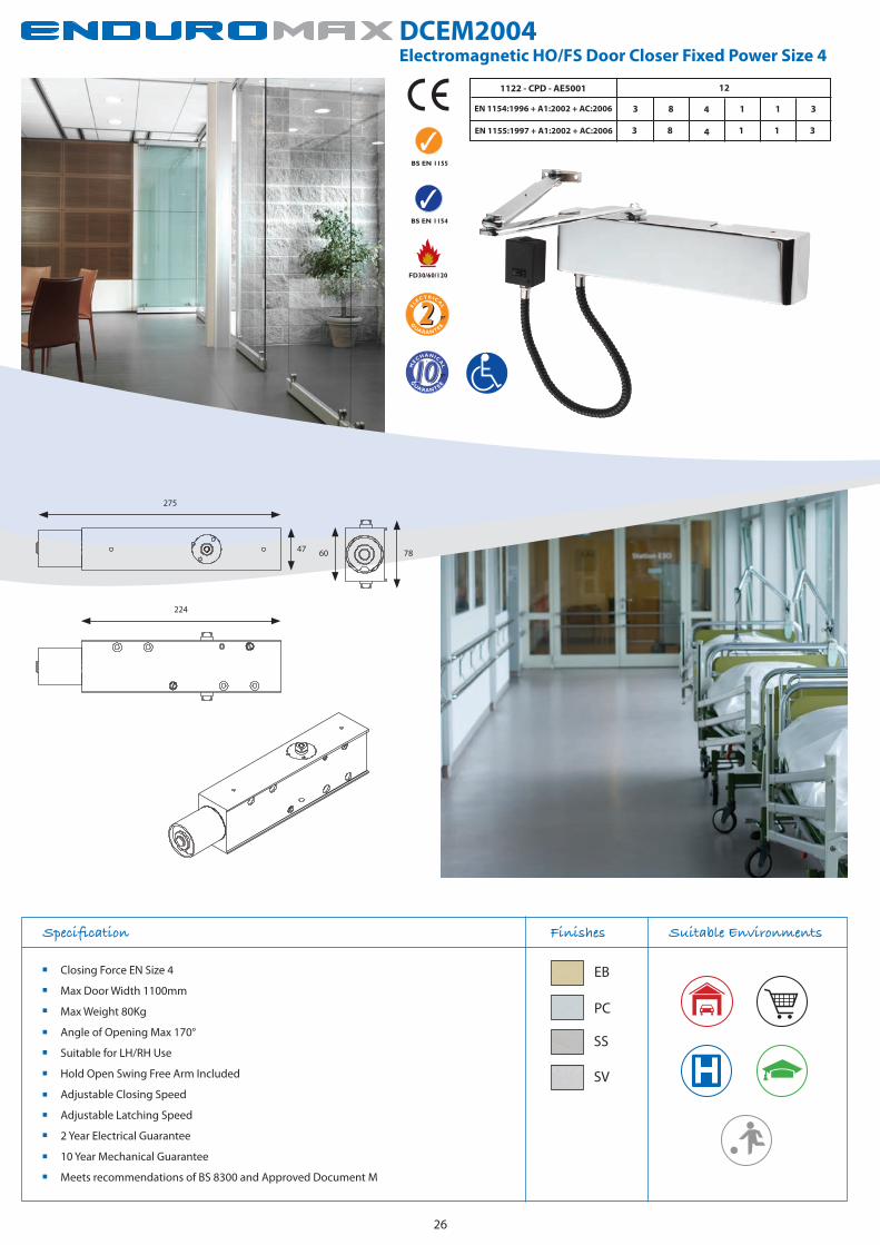
DCEM2004Electromagnetic HO/FS Door Closer Fixed Power Size 4
Specification Finishes
Closing Force EN Size 4
Max Door Width 1100mm
Max Weight 80Kg
Angle of Opening Max 170°
Suitable for LH/RH Use
Hold Open Swing Free Arm Included
Adjustable Closing Speed
Adjustable Latching Speed
2 Year Electrical Guarantee
10 Year Mechanical Guarantee
Meets recommendations of BS 8300 and Approved Document M
Suitable Environments
26
1122 - CPD - AE5001
EN 1154:1996 + A1:2002 + AC:2006
12
3 8 1 1 34
EN 1155:1997 + A1:2002 + AC:2006 3 8 1 1 34
EB
PC
SS
SV
275
224
47 7860
BS EN 1154
FD30/60/120
BS EN 1155
G
UARANTEE
yr
EC ICAL
RT
EL
G
UARANTEE
MECHANICA
L
yr

ELECTROMAGNETIC ACCESSORIES
27
The Home of Quality Architectural Ironmongery
Product Finishes Product Finishes
DEM100S
Surface Mounted Wall Magnet
Product Finishes Product Finishes
DEFB100
Floor Mounting Bracket
DEM100F
Flush Mounted Wall Magnet
PSUA8/WHT
1 Amp 24v DC Power Supply Unit
Optional Special Order Only:
3 Amp PSUA8/3/WHT
5 Amp PSUA8/5/WHT
* see page 28 for technical details.
SV SS
SV
SS
SV
WHT
G
UARANTEE
yr
EC ICAL
RT
EL

28
Transformer Rectifiers Explained...
Transformer Rectifiers 24V DC
Our range of Transformer Rectifiers are designed for our DCEM range of Electronic door closers where a smooth 24v dc supply is required. Each power supply features full monitoring of all circuitry with fault conditions displayed by means of a single yellow LED indicator.
The Transformer Rectifiers will also monitor mains fail and output fuse fail. The output voltage is regulated throughout the Transformer Rectifier range and all models are able to supply full rated output.
Our Transformer Rectifiers have a relay fitted which controls the output in either energised or de energised state through two methods of switching. The relay can be triggered by either applying 24v to coil from a remote source or through the use of a remote volt free switch connected to the “THRU LINK” terminals. The relay can be operated by any external switching source such as a fire alarm panel or other control system.
Our Transformer Rectifiers also feature the incorporation of an additional fault relay which can be used to signal the power supply status to a remote monitoring system, remote indicator or buzzer unit. In addition the relay can also be used to provide an input to an addressable switch monitor in order to make the Transformer an integral part of any addressable system.
All Transformer Rectifiers we supply carry the CE mark and are fully compliant with the LVD9 Low Voltage Directive.
PSUA8/WHT = 1 Amp
Will power upto 6 units when using
1.5mm wire or will power upto 8 units
when using 2.5mm wire
Rating: 1A@24v dc
Input Voltage: 240AC, 230AC
Output Volts: 24v dc
Floating Voltage: 27.4 - 29.0
PSUA8/3/WHT = 3 Amp*
Will power upto 18 units when using
either 1.5mm or 2.5mm wire.
Rating: 3A@24v dc
Input Voltage: 240AC, 230AC
Output Volts: 24v dc
Floating Voltage: 27.4 - 29.0
PSUA8/5/WHT = 5 Amp*
Will power upto 44 units when using
1.5mm wire or will power upto 50 units
when using 2.5mm wire.
Rating: 5A@24v dc
Input Voltage: 240AC, 230AC
Output Volts: 24v dc
Floating Voltage: 27.4 - 29.0
Fully compliant with LVD9 low voltage directive.
CE marking.
Suitable for all options of fire alarm systems.
In-built relay.
“THRU LINK” terminals to suit older fire alarm systems.
NOTE:
50 metre max total cable length from power supply unit for above calculations.
As a guideline e.g if using 100m of cable, reduce the amount of unit coverage by 50%.
*Special Order Only *Special Order Only

29
Suitable for LH/RH Use
Radius Version Available AA45R
AA45 Concealed Chain Spring Door Closer Finishes Suitable Environments
CP
PB
CDG003 Contract Overhead Door Closer Fixed Power Size 3 Finishes
Closing Force EN Size 3
Efficiency 66%
Max Door Width 950mm
Max Weight 60Kg
Angle of Opening Max 180°
Suitable for LH/RH Use
Adjustable Closing Speed
Adjustable Latching Speed
2 Year Mechanical Guarantee
Accessory Packs Available
Suitable Environments
Max Door Width 940mm
Max Weight 80Kg
Angle of Opening Max 110°
Suitable for LH/RH Use
CDC85/R Adjustable Jamb Mounted Door Closer Finishes Suitable Environments
SC
G
UARANTEE
MECHANICA
L
yr
FD30
SC
SV
G
UARANTEE
MECHANICA
L
yr
BS EN 1154:1996 - Fig 1 Fitting
4 8 1 1 33
BS EN 1154:1996 - Fig 6 Fitting
4 8 1 1 33
BS EN 1154FD30/60
G
UARANTEE
MECHANICA
L
yr
144.5
3.5
R 22.5
25
50
59.4
25.5
170
25
4.2
123
25.5
ANCILLARY PRODUCTS
PSUA8/5/WHT = 5 Amp*
Will power upto 44 units when using
1.5mm wire or will power upto 50 units
when using 2.5mm wire.
Rating: 5A@24v dc
Input Voltage: 240AC, 230AC
Output Volts: 24v dc
Floating Voltage: 27.4 - 29.0
FD30/60

30
Troubleshooting and Maintenance
Door closer cannot close easily
For o/hd closers disconnect arms
Does closer mechanismoperate freely?
Adjust or replace door closer
Does the door move freely? Are the hinges plumb? Adjust or ease hinges
Are the hinges stiff? Lubricate hinges
Re-connect closer arms Is the door scraping the floor?
Re-hand door or plane bottom rail
Is latch resistance too strong?
Adjust strike plate and lubricate latch
Is the door catching the frame?
Ease door and/or frame
Is the closer correctly installed?
Re-position closer according to template/instructions
Is the closer the right size for the door?
Replace closer or adjust spring strength where possible
Door closer closes the door easily
NO
NO NO
YES
YES
YES
YES
NO
NO
YES
YES
YES
NO
NO
NO
1. Check that all instructions provided by the manufacturer are adhered to and that the door closer closes the door correctly.
2. Ensure that all fixing screws, including the connection of arm to body are tight.
3. Check the spring strength is set correctly and adjust if necessary.
4. Perform checks on any controls relating to delay, closing speed, latching action and back check, and adjust as required.
5. Lightly lubricate arm joints and rollers with light oil or grease.
6. Ensure that at all times, care and maintenance are carried out by competent personnel and that records are kept.
7. Use chart below as a guide to checking your doorset.

31
Fitting Applications
Figure 61 (Fig 61) Transom Mounted Application
Figure 66 (Fig 66) (Fig 6) Parallel Arm Application
Figure 1 (Fig 1) Straight Arm ; Standard Application
Our comprehensive range of Enduro and Enduromax door closers all come with detailed fitting instructions and technical information.
The three common ways to fit surface mounted overhead closers are as follows. The full range of fitting instructions in PDF format can be obtained from
www.carlislebrass.com
The closer is mounted on the pull side of the door with the arm fixed to the frame on the hinge knuckle side of the door.
Door Application: Offices, stores, toilets etc, where doors open into areas which are usually small.
The closer is mounted on the push side of the door and the arm is fixed to the Figure 66 bracket, parallel to the door on the opposite side of the door to the hinge knuckle.
Door Applications: Doors opening outwards to exterior, where aesthetics or space mean Figure 1 cannot be used.
The closer is mounted on the push side of the frame over the door and the arm is fixed to the door on the opposite side to the hinge knuckle.
Door Applications: Doors where there is insufficient material in the top rail to allow the closer to be fitted on glazed doors with unsufficient fixing for closer body.

32
Index
AA45 29
29
29
14,17
13,15,16,18
24
25
26
6
20
20
8
9
10
7
21
21
19
19
11
11
11
11
19
20
20
20
21
27
27
22
22
27
CDC85SC/R
CDG003
DCC2003
DCC2024
DCCEM3024
DCEM2003
DCEM2004
DCF2003
DCFS150
DCFS250
DCS2024
DCS2025
DCS2026
DCT2024
DCTS100
DCTS150
DCX2002
DCX2003
DCX2107
DCX2201
DCX2202
DCX2203
DCX3202
DCXF105
DCXF107
DCXF108
DCXT100
DEFB100
DEM100
H2N1900
H2N1950
PSUA8

Notes

Carlisle BrassParkhouse Road
CarlisleCA3 0JU
Email: [email protected]: www.carlislebrass.com
Tel: 01228 511030Fax: 01228 511885