building information modeling (bim) application in civil ... · building information modeling (bim)...
TRANSCRIPT
RESEARCH ARTICLE
Building information modeling (BIM) application in civilconstructions intending the increase of service life
A. Marchini1 • J. O. Patzlaff1
Received: 27 June 2016 / Accepted: 5 October 2016 / Published online: 2 November 2016
� Springer International Publishing Switzerland 2016
Abstract The use of building information modeling
methodology in project design and planning of civil con-
struction processes can contribute throughout the building
lifecycle. In the various stages, the degree of assertiveness
tends to increase because the information is worked toge-
ther, allowing a better understanding of the details to be
met. In addition, to facilitate the implementation, this
process can also work in the post-project phase, through the
support to the user before the need of building mainte-
nance. These two stages, construction process and after
work, when worked together, can directly influence the
service life of the systems that make up the building. In this
context, this paper aims to demonstrate how the project
(three-dimensional model) can be worked along in the
planning process and how the information on the mainte-
nance process can be linked to the project. Its method
consists in the implementation of 4D planning in a build-
ing, linking model and schedule, and listing the major
maintenance of the major building systems, linking them to
the project as parameterized information. Among the
results, there is the viability of 4D planning and the linking
of routines associated with the maintenance activities of the
building project. Finally, it is concluded that the use of new
technologies for the development of projects and support in
the planning stages can directly influence the quality of the
enterprise and the service life of the buildings when used
properly.
Keywords BIM � Management � Planning � Design �Service life � Construction � Maintenance
1 Introduction
The building information modeling (BIM), has become a
promising field in regards of the integration and com-
patibility of both projects and information, as in plan-
ning, management, projective or executive, providing
support to the steps of the construction process [1]. This
technology is no longer seen only as a non-conformities
or conflicts identifier through the integrating process
management activities, resulting in a higher degree of
reliability and quality by reducing design errors and thus
reducing costs [2].
The technology can also assist in the information in a
management context where the whole process of imple-
mentation of buildings is based on paper documents, gen-
erating such a large volume of material that facilitates the
occurrence of errors that bring consequences to the project,
usually associated with unforeseen costs. BIM technology
incorporates all relevant information to the project in a
single model, reducing the possibility of the occurrence of
errors and increasing the speed of communication [1].
In this context, the possibility of integrating a three-
dimensional model of the building in their planning,
becomes important in the management of the executional
process, where all the elements of the model will be joint
together in a particular activity, contributing to its correct
execution. This binding process within the architectural
Electronic supplementary material The online version of thisarticle (doi:10.1007/s41024-016-0009-2) contains supplementarymaterial, which is available to authorized users.
& A. Marchini
J. O. Patzlaff
1 UNISINOS, Av. Unisinos, 950, Bairro Cristo Rei,
Sao Leopoldo, RS CEP 90.022-750, Brazil
123
J Build Rehabil (2016) 1:12
DOI 10.1007/s41024-016-0009-2

design methodology is called as the fourth dimension of
BIM or BIM 4D methodology.
In addition to the benefits related to the management of
the activities with the consequent reduction of failures and
increased quality, through BIM 4D there is an improve-
ment in the safety during the work, due to the possibility of
virtually planning the construction, including temporary
elements such as cranes, trucks, hoists, fences, service
elevators, among others [3].
The management of the planned work day by day can
also be improved and developed with the help of data
provided by BIM tools, due to the ability to generate
accurate bills of all stages of work, facilitating the purchase
planning and storage of materials. This process makes the
job leaner because it optimizes time and space, reducing
storage space within the site.
Having access to the model in three dimensions, ques-
tions regarding storage sites or even how to perform a
certain task can be quickly answered verifying the model.
This way, there may be more emphasis on quality of
executive steps over tasks of lesser importance of the
implementation process [1]. In short, through integrated
methodologies of project management, including the sum
of many benefits at all stages, there’s a tendency to the
decrease the construction errors, increasing the construc-
tion quality and, consequently, increased service life of the
construction or systems that compose it.
Adding to the 4D construction planning process, the
benefits can also extend to after work, through the man-
agement of building maintenance cycle within the BIM
methodology, called the sixth dimension of BIM or BIM
6D, where it’s possible to enter information concerning the
warranty of equipment, maintenance of equipment and
planning systems, manufacturing data and life and even
illustrations [4].
In the BIM 6D, the final model will contain all
information relevant to the construction described in the
operation manual and maintenance of systems, such as
preventive maintenance, warranties and specifications.
The process of maintenance of buildings is an essential
requirement to reach or extend the service life expected
the building. Thus it is of utmost importance that main-
tenance activities are of the user’s knowledge, whether
through the use of manual and operation or through 6D
BIM models [3]. The maintenance of the building is a set
of activities and interventions that must be performed in
the building during its service life so that it remains
preserved or regain the ability to use [5], and its execu-
tion is the user’s responsibility [6]. The sixth dimension
models can be accessed and viewed by users through
facilitated means of view as PDF or 3D PDF due to the
need to apply knowledge of BIM software for viewing
within the platform.
The main objective of this paper is to demonstrate the
applicability of BIM in the design phase to ensure a better
schedule during the construction phase and also during the
service life, through the specification of the needed main-
tenance of each component of the building. The service life
of the building and its systems can be best understood from
Fig. 1, which notes the need to perform maintenance pro-
cesses to achieve it. In the image, ‘‘T0’’ represents the
beginning of the service life of the construction, ‘‘T1’’
represents a theoretical service life without maintenance,
while ‘‘T2’’ represents a theoretical service life with
maintenance.
2 Research method
2.1 Planning management through BIM 4D
BIM 4D means the integration of schedules with the
building’s design and 3D model. 4D planning BIM is one
of the main applications of this technology, because it
gives designers a new way to view the generated schedules,
through computer simulations, created by the linking of the
construction schedule to the three-dimensional model,
enabling the work to be performed as previously defined in
the design phase.
For this part of the paper, it was used the design and
construction schedule of a multifamily residential condo-
minium, located in the city of Novo Hamburgo, consisting
of eighteen high standard two story housing units. The
condo is also comprised of a ballroom, playground and
guardhouse. The design of this condo was fully realized in
BIM, including architectural design, plumbing and struc-
tural design, using Revit Architecture.
To start the development of 4D planning, it was
attempted to perform two activities schedules so that they
could later be compared side by side in video form. Thus
two schedules were prepared, called A and B, using
Fig. 1 Performance recovery for maintenance actions [5]
12 Page 2 of 9 J Build Rehabil (2016) 1:12
123

Microsoft Project. The schedule A refers to the initial
proposal of the work, disregarding any delays resulting
from climatic variations, the delivery of materials and lack
of manpower. The B schedule is the schedule supposedly
real (at the end of the production period), covering all
possible delays that may occur during the implementation
period. The schedules have been created in this way
because of the inability to be based on a real schedule of
implementation due to fact that there has not been any
activity of this kind during the development of this
research. Thus, in the schedule B it was added a correction
factor of 30 % to simulate the possible delays during the
construction period.
To do the integration of schedules developed, Autodesk
Navisworks was used. The software has the function to
associate the schedule to their respective items on the
three-dimensional model, generating, automatically, virtual
simulations of the building. In a previous analysis, focusing
only on schedule simulation the designer can already see
the building being built virtually, according to the schedule
created and examine whether the steps thought initially
comply with the predictions, or if you can optimize the
schedule through better sequencing activities.
In a second step, in possession of the two simulations, it
is possible to perform the comparison of both. Thus the
simulations were compared and placed side by side, in the
form of video, enabling a new way of viewing the stages of
progress of the two schedules. This procedure has the main
function of allowing the comparison of the difference
between the timelines, that is, to provide a physical and
comparative visualization of the stages of progress of the
work, delays or advances, which is usually given in days
and months in the three-dimensional model, in addition to
providing a tool that allows new and different analyzes on
the schedule.
2.2 Management building maintenance process
The ABNT NBR 15575-1:2013 (Brazil’s residential
building’s performance standard) made the role of the
owner or user even more important in the maintenance
process and the life cycle of the building systems, because
to achieve the proposed service life, its intervention is
essential. This process made the development of the
manual of use and operation a fundamental requirement for
the development of this new and growing need, also
seeking new ways to link this information to the project. It
is known that BIM platform design allows multiple pos-
sibilities of integration, and to include information about
maintenance program is one of them. This process of
integration of these data aims to facilitate the user main-
tenance process, in addition to making the design more
complete, covering a large part of the building’s life cycle.
Having access to the virtual building design, which will
contain the maintenance data, the user now has a global
vision of the systems that make up the building and their
preventive maintenance, as well as a practical view of these
local maintenance.
In order to facilitate the linkage of maintenance infor-
mation to the design of residential condominium men-
tioned above, it was sought to use methods that the
software itself (Revit Architecture) provides, the creation
of parameters or maintenance parameters. Revit Architec-
ture is a parametric software, i.e. works by parameters that
can be color, type, shape, size, thickness, and any other
type of information and detail of the project components.
Thus, maintenance of information was linked to the project
and their respective systems via a parameter in text form.
To initiate this process, first, a parameter group called
maintenance needed to be created. Within this group sub-
parameters were created to the types of maintenance that
must be performed in a given family project.
Subsequently to the creation of sub-parameters, they
were bound to their respective families, for example, sub-
parameters Maintenance Paint-type have been linked to
walls family, maintenance-type glasses were linked to the
frames family.
After these bindings were done, spaces are created
(white gaps) within the properties of families, so that the
maintenance program information is described. Once the
necessary information is entered, it can be said that it is
already part of the project or family, or the 6D. For this
project, it is desired that this information can be viewed on
the project, in floor plans, sections, elevations and three-
dimensional views, so labels for each type of sub-param-
eter were created, allowing the information to be read in
the project and not only within the family of properties.
All information related to the maintenance program of
the building systems were based on the Brazil National
Guide to Drafting Manual of Use, Operation and Mainte-
nance of Buildings (CBIC, 2014). The CBIC manual fol-
lows the guidelines and provisions of the ABNT NBR
14037: 2011 (operating manual, use and maintenance of
buildings—content and recommendations for preparation
and presentation), ABNT NBR 5674: 2012 (maintenance
of buildings—procedure) and ABNT NBR 15575: 2013
(residential buildings—performance). Due to the fact that
the maintenance program of the CBIC manual extends to
all systems that make up a building, some systems were
selected for the demonstration of its application viability.
Thus, the frame systems, painting, textures, varnishes,
glass and cover were addressed.
The program consists of fifty-two different systems, of
which four were chosen to be linked to the project in order
to demonstrate the process. The data used in the project are
shown in tabular form for each verified system.
J Build Rehabil (2016) 1:12 Page 3 of 9 12
123
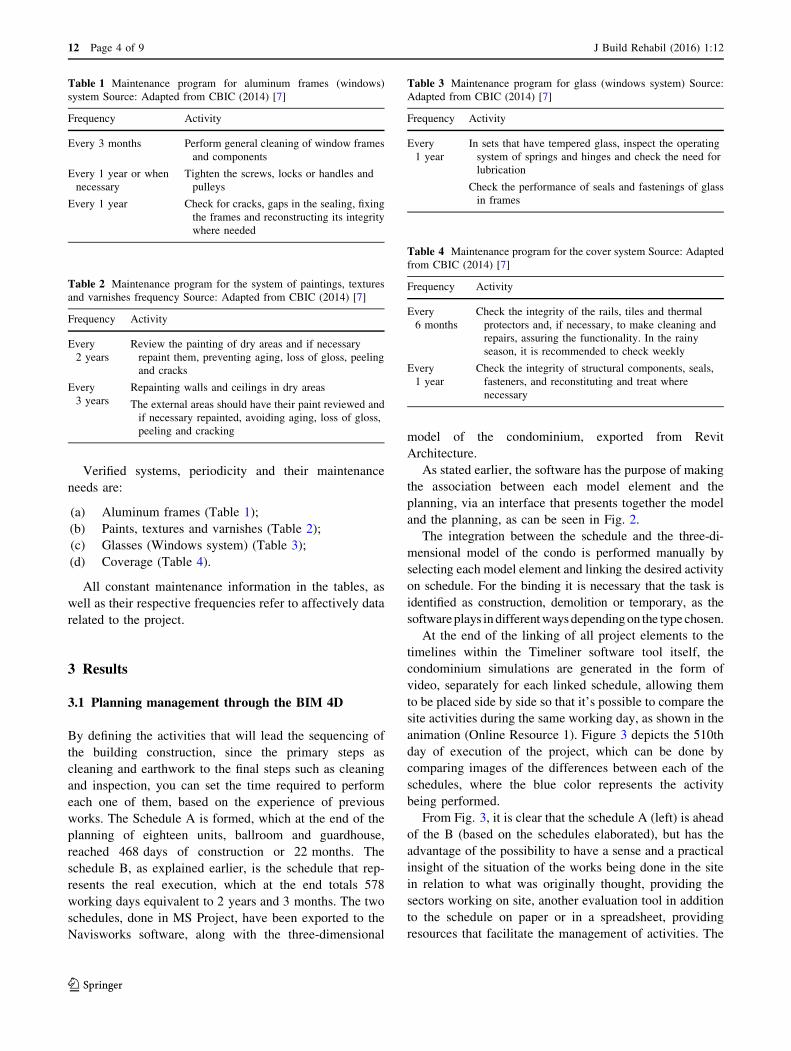
Verified systems, periodicity and their maintenance
needs are:
(a) Aluminum frames (Table 1);
(b) Paints, textures and varnishes (Table 2);
(c) Glasses (Windows system) (Table 3);
(d) Coverage (Table 4).
All constant maintenance information in the tables, as
well as their respective frequencies refer to affectively data
related to the project.
3 Results
3.1 Planning management through the BIM 4D
By defining the activities that will lead the sequencing of
the building construction, since the primary steps as
cleaning and earthwork to the final steps such as cleaning
and inspection, you can set the time required to perform
each one of them, based on the experience of previous
works. The Schedule A is formed, which at the end of the
planning of eighteen units, ballroom and guardhouse,
reached 468 days of construction or 22 months. The
schedule B, as explained earlier, is the schedule that rep-
resents the real execution, which at the end totals 578
working days equivalent to 2 years and 3 months. The two
schedules, done in MS Project, have been exported to the
Navisworks software, along with the three-dimensional
model of the condominium, exported from Revit
Architecture.
As stated earlier, the software has the purpose of making
the association between each model element and the
planning, via an interface that presents together the model
and the planning, as can be seen in Fig. 2.
The integration between the schedule and the three-di-
mensional model of the condo is performed manually by
selecting each model element and linking the desired activity
on schedule. For the binding it is necessary that the task is
identified as construction, demolition or temporary, as the
softwareplays indifferentwaysdependingon the typechosen.
At the end of the linking of all project elements to the
timelines within the Timeliner software tool itself, the
condominium simulations are generated in the form of
video, separately for each linked schedule, allowing them
to be placed side by side so that it’s possible to compare the
site activities during the same working day, as shown in the
animation (Online Resource 1). Figure 3 depicts the 510th
day of execution of the project, which can be done by
comparing images of the differences between each of the
schedules, where the blue color represents the activity
being performed.
From Fig. 3, it is clear that the schedule A (left) is ahead
of the B (based on the schedules elaborated), but has the
advantage of the possibility to have a sense and a practical
insight of the situation of the works being done in the site
in relation to what was originally thought, providing the
sectors working on site, another evaluation tool in addition
to the schedule on paper or in a spreadsheet, providing
resources that facilitate the management of activities. The
Table 1 Maintenance program for aluminum frames (windows)
system Source: Adapted from CBIC (2014) [7]
Frequency Activity
Every 3 months Perform general cleaning of window frames
and components
Every 1 year or when
necessary
Tighten the screws, locks or handles and
pulleys
Every 1 year Check for cracks, gaps in the sealing, fixing
the frames and reconstructing its integrity
where needed
Table 2 Maintenance program for the system of paintings, textures
and varnishes frequency Source: Adapted from CBIC (2014) [7]
Frequency Activity
Every
2 years
Review the painting of dry areas and if necessary
repaint them, preventing aging, loss of gloss, peeling
and cracks
Every
3 years
Repainting walls and ceilings in dry areas
The external areas should have their paint reviewed and
if necessary repainted, avoiding aging, loss of gloss,
peeling and cracking
Table 3 Maintenance program for glass (windows system) Source:
Adapted from CBIC (2014) [7]
Frequency Activity
Every
1 year
In sets that have tempered glass, inspect the operating
system of springs and hinges and check the need for
lubrication
Check the performance of seals and fastenings of glass
in frames
Table 4 Maintenance program for the cover system Source: Adapted
from CBIC (2014) [7]
Frequency Activity
Every
6 months
Check the integrity of the rails, tiles and thermal
protectors and, if necessary, to make cleaning and
repairs, assuring the functionality. In the rainy
season, it is recommended to check weekly
Every
1 year
Check the integrity of structural components, seals,
fasteners, and reconstituting and treat where
necessary
12 Page 4 of 9 J Build Rehabil (2016) 1:12
123

same tool can be used to evaluate various types of sched-
ule, defining what best fits constructively to the company’s
standards, that is, there are many practical uses in this type
of comparison view.
3.2 Management building maintenance process
Preventive maintenance of buildings has always been of
utmost importance to its life cycle, as they ensure quality,
comfort and safety for a longer period. But this is not
always the understanding of owners who end up not
making the necessary treatment, either by carelessness,
forgetfulness or the costs to perform these maintenances.
Over time, concerns for the maintenance began to gain
more importance, both for manufacturers and for the
owners, through the preparation of manuals of use and
operation, which must present the terms of warranty and
maintenance plans.
A fact that made these interventions become even more
important was the emergence of NBR 15575: 2013, because
the maintenance is necessary for the systems to reach the
Design Service Life, exacerbating the responsibility of
owner and/or user facing the maintenance of its building,
plus the fact that it is the owner’s responsibility to carry them
out, asNBR5674:2012 points out, andmeet the provisions of
the operating manual and property operation. Within the
BIM methodology, there is BIM 6D, which is the denomi-
nation of the link between the information in the manual of
use and operation, with regard to post-work, i.e. the entire life
cycle of the building, after delivering the keys to the owner.
Along with the house keys, the manual of use and operation
of the buildingmust be delivered to the owner, aswell, whose
elaboration is of responsibility of the builder or developer.
One of the parts of this manual is the maintenance program,
which provides a list of key systems that constitute the
building and the indication of maintenance and deadlines to
be met for each of these systems.
In this way we sought to link the maintenance program
of some systems to the project of the residential condo-
minium units mentioned above, aiming to demonstrate the
process of executing a 6D model. The analyzed mainte-
nance program was based on the National Guide for the
Preparation of the Manual of Use, Operation and Mainte-
nance of Buildings [7].
The linkage of the information shown in the
tables above was conducted with Revit Architecture, by
creating parameters for each type of maintenance required,
allowing the linking of them to the project.
In this software, the project consists of families that
must be developed during the design process. In addition to
the geometric shape, these families are made up of
parameters that characterize the objects as a material,
width, length, and every other necessary information of the
object. In this way the program allows you to delete, edit
and even create new parameters, enabling the inclusion of
varied characteristics families.
This process also allows the linking of any kind of
information to the project, by setting parameters, to be
inserted in text form, or the inclusion of a feature that will
not affect the shape or appearance. Through this process,
the information becomes part of the object and is linked to
it at all locations where it is used in the project.
Fig. 2 Example of schedule linking (4thD) on the dimensional model (3D) in the software
J Build Rehabil (2016) 1:12 Page 5 of 9 12
123

Thus sub-parameters were created to insert the desired
information related to the maintenance program. To create
the sub-parameter, a parameter group called maintenance
had to be created. Within this group of parameters sub-
parameters were created related to each type of service.
Maintenance sub-parameters were created based on the
names of each system, as shown in Fig. 4.
After the creation of all the sub-parameters, it’s reported
to the software to which family the parameter should be
added. The coverage parameters must be added to the roof
family, frames parameters to the windows family, painting
parameters to the walls family and the glasses parameters
as well as the windows family.
Completed the insertion of the parameters of the cor-
responding families, a field is available in its properties,
next to each parameter set up, which is part of the main-
tenance data of each system, as shown in Fig. 5.
After entering the information for all the parameters cre-
ated within their corresponding families, the integration of
data from the completed maintenance program is considered
and linked to the project and the three-dimensional model,
making this data part of the families that compose them. Data
can be read or viewed through the properties of each system.
The link makes it possible to create automatic labels for
identifying information on floor plans, views, elevations,
sections and three-dimensional views.
The label serves to identify, automatically, a determined
information within the systems that should be indicated by
the designer which information you want the label to
interpret, so that its needed only to select the family in the
project and the information will be searched automatically,
becoming visible and indicated through the lines or arrows.
This way, as it’s wanted to identify all project parameters,
we created a label for each parametermaintenance, so that all
data entered are visible in selected views as Figs. 6 and 7.
The integration of the maintenance program in the design
meets the objectives of this design methodology, which is to
seek the integration of all kinds of information to the project,
within a single model capable of portraying all stages of the
building, from its initial conception, modeling, construction,
life cycle until its final destination, either demolition or reuse.
In addition to being linked to the families of the project, this
kind of identification allows the user the practical visualiza-
tion of where maintenance should bemade through simplified
viewing platforms, such as PDF or 3D PDF. Figure 7 shows
the construction in a general point of view, but it’s possible to
get tomore specific details and exact position ofmaintenance,
even in plumbing and electrical systems when modeled.
The maintenance program within the BIM is the first
step of linking information comprising the model 6D, in
order to have a more complete project within a single
platform, not only in manuals or other sources, facilitating
the obligations of designers and users.
4 Final
The use of more advanced methods for the preparation of
projects, in this case referring to the Building Information
Modeling can bring some advantages to the project, for the
Fig. 3 Comparison of the schedules A (schedule done during the design phase) and B (real schedule) during the 510th day
12 Page 6 of 9 J Build Rehabil (2016) 1:12
123

Fig. 4 Creating sub-parameters for the Maintenance Program
Fig. 5 Inserting the performance specifications of the parameters
J Build Rehabil (2016) 1:12 Page 7 of 9 12
123

Fig. 6 Identification of the Demo Floor Plan of Maintenance Information for Walls Systems, Frames and windows
Fig. 7 Identification of the demonstration in view of the three-dimensional Maintenance Information for Walls Systems, Frames, Glass and
coverage
12 Page 8 of 9 J Build Rehabil (2016) 1:12
123

construction and the post-work management. When plan-
ning the construction of a building through the BIM 4D
methods, the probability of having a better planning tends
to increase as the deadlines may be better suited to the
tasks (avoiding work overload and consequent decrease in
quality), identifying critical tasks and especially defining in
project all the details before it goes to the site, reducing
decisions in situ, which may end up compromising some
systems due to the non-correct procedures performed.
Maintenance activities during the life cycle of the building,
after the occupation, has a very important role in the
conservation of all systems, working directly in the service
life of the building. It is known that the performance
required over the years tends to diminish, needing these
activities to achieve the minimum performance and to
increase the time that the building can be used for its
original purpose. Thus, it is considered extremely impor-
tant to the user’s role on these activities. The development
of the model 6D has to assist the user’s role and promote
greater effectiveness of maintenance, in cooperation with
the use of manual of maintenance and operation. With the
6D template, the user becomes aware of all systems that
compose the building (resulting in a three-dimensional
model), and see the exact location where maintenance
should be made. That is, the 6D model is a three-dimen-
sional summary maintenance program, where the infor-
mation is grouped together for each system type and
displayed in the project, aiming a better experience and
interpretation of the user front before maintenance is
needed.
Together, all these steps can actively interfere and allow
the considerable increase of service life to the building and
systems that make them up. The use of these methods alone
do not guarantee the increase of service life to the building,
it is necessary that they are well thought out and properly
executed to be effective, as a bad project using new
methodologies, will remain a bad project regardless of the
platform that it is made on. However, on a good design,
these methods can bring positive results to the service life
and the building as a whole.
References
1. Eastman C et al (2011) BIM handbook—a guide to building
information modeling for owners, managers, designers, engineers
and contractors. Digital Version
2. Silva FAC (2015) Construtoras, entidades e fornecedores se
mobilizam e aumentam uso do processo de Modelagem da
Informacao da Construcao Civil. Construcao, Sao Paulo, v. 162,
jan. http://construcaomercado.pini.com.br/negocios-incorporacao-
construcao/162/construtoras-entidades-setoriais-e-fornecedores-
se-mobilizam-e-aumentam-uso-335413-1.aspx. Accessed 16 Mar
2015
3. Rendeiro JE (2013) Apresentando o BIM—primeira parte. Engen-
haria do Futuro, 2013. http://engdofuturo.com.br/apresentando-o-
bim-1a-parte/. Accessed 11 Mar 2015
4. Mattos AD (2014) BIM 3D, 4D, 5D e 6D. Pini Blogs. http://blogs.
pini.com.br/posts/Engenharia-custos/bim-3d-4d-5d-e-6d-335300-
1.aspx/. Acesso em 12 Mar 2015
5. Associacao Brasileira de Normas Tecnicas (ABNT) (2013) NBR
15575-1: Edificacoes habitacionais—Desempenho—Parte 1:Req-
uisitos Gerais. Rio de Janeiro
6. ASSOCIACAO BRASILEIRA DE NORMAS TECNICAS
(ABNT) (2012) NBR 5674: Manutencao de edificacoes—Proced-
imentos. Rio de Janeiro
7. CBIC (2014) GUIA NACIONAL PARA ELABORACAO DO
MANUAL DE USO, OPERACAO E MANUTENCAO DAS
EDIFICACOES. Brasılia, DF
J Build Rehabil (2016) 1:12 Page 9 of 9 12
123