building an computer adder. building an adder no matter how complex the circuit, or how complex the...
Post on 20-Dec-2015
230 views
TRANSCRIPT

Building an Computer Adder
Building an Adder
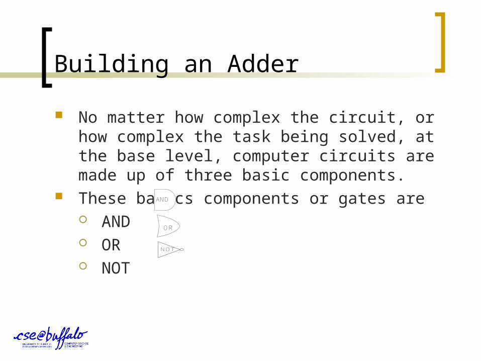
No matter how complex the circuit, or how complex the task being solved, at the base level, computer circuits are made up of three basic components.
These basics components or gates are AND OR NOT NOT
AND
OR
Building an Adder
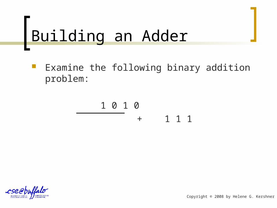
Examine the following binary addition problem:
1 0 1 0
+ 1 1 1
Copyright © 2008 by Helene G. Kershner

Building an Adder
Examine the following binary addition problem:
1 0 1 0
+ 1 1 1
1
Copyright © 2008 by Helene G. Kershner

Building an Adder
Remember that in binary addition there are only five possible numeric combinations. 1 Carry In
0 0 1 1 1
+ 0 + 1 + 0 + 1 1
0 1 1 1 0 and 1 1
Carry Out
to next digit
Copyright © 2008 by Helene G. Kershner

Building an Adder
Let’s put this information in a table.
If we rotate this table placing the A, B and Sum at the top we get what looks like a standard turth table.
A 0 0 1 1
+
B 0 1 0 1
Sum 0 1 1 10
A B Sum
0 0 0
0 1 1
1 0 1
1 1 10

Building an Adder A computer will treat each column of digits in our binary
addition as one operation.
1 0 1 0 + 1 1 1
1 Essentially the computer uses the circuit designed to
implement the table below to solve each column.A B S
0 0 0 0 1 1 1 0 1 1 1 (1) 0
Ignore the 1 which carries to
next column for the moment!
Copyright © 2008 by Helene G. Kershner
Building an Adder
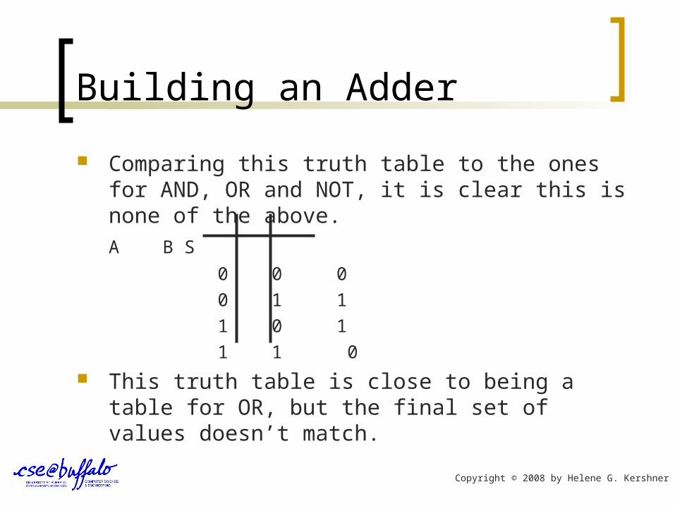
Comparing this truth table to the ones for AND, OR and NOT, it is clear this is none of the above.
A B S
0 0 0
0 1 1
1 0 1
1 1 0
This truth table is close to being a table for OR, but the final set of values doesn’t match.
Copyright © 2008 by Helene G. Kershner

Building an Adder
Using basic logic gates computer architects designed the following circuit to match the truth table for adding two binary digits.
A
B
S
Copyright © 2008 by Helene G. Kershner
Building an Adder
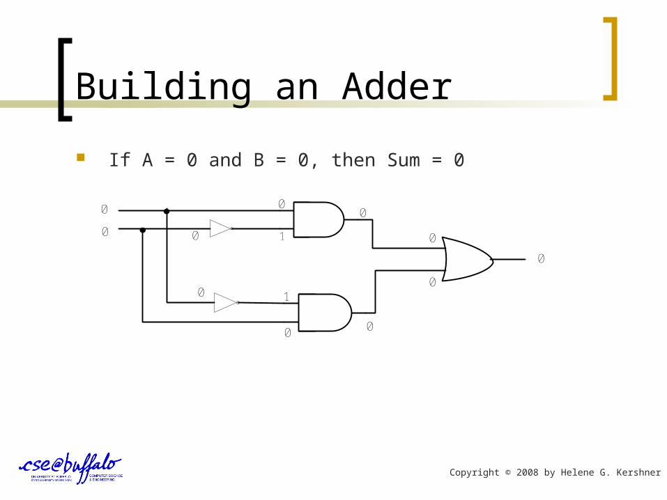
If A = 0 and B = 0, then Sum = 0
0
0
0
0
1
1
0 0
0
0
0
0
0
Copyright © 2008 by Helene G. Kershner

Building an Adder
If A = 0 and B = 1, then Sum = 1
0
1
1
0
01
10
1
0
1
Copyright © 2008 by Helene G. Kershner

Building an Adder
If A = 1 and B = 0, then Sum = 1
1
0
1
1
10
01
0
1
0
Copyright © 2008 by Helene G. Kershner

Building an Adder
If A = 1 and B = 1, then Sum = 0.
1
1
0
1
1
1
0 0
0
0
0
0
0
0
Copyright © 2008 by Helene G. Kershner
Building an Adder
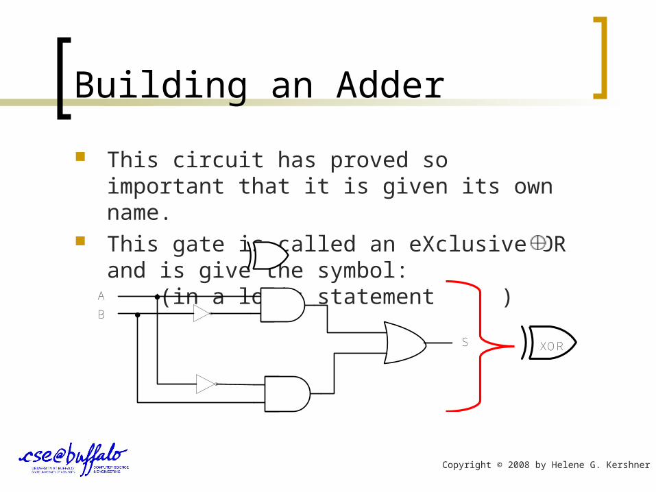
This circuit has proved so important that it is given its own name.
This gate is called an eXclusive OR and is give the symbol: (in a logic statement )
A
B
S
XOR
Copyright © 2008 by Helene G. Kershner
Building an Adder
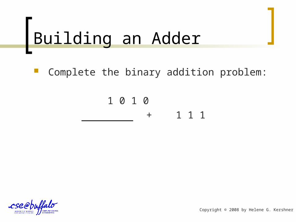
Complete the binary addition problem:
1 0 1 0
+ 1 1 1
Copyright © 2008 by Helene G. Kershner
Building an Adder
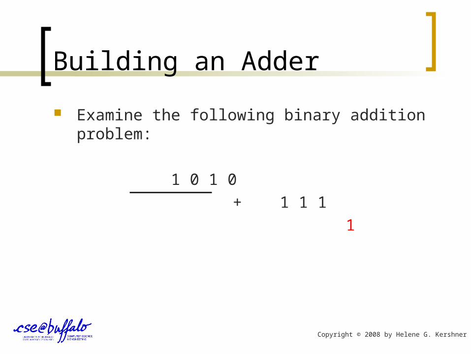
Examine the following binary addition problem:
1 0 1 0
+ 1 1 1
1
Copyright © 2008 by Helene G. Kershner
Building an Adder
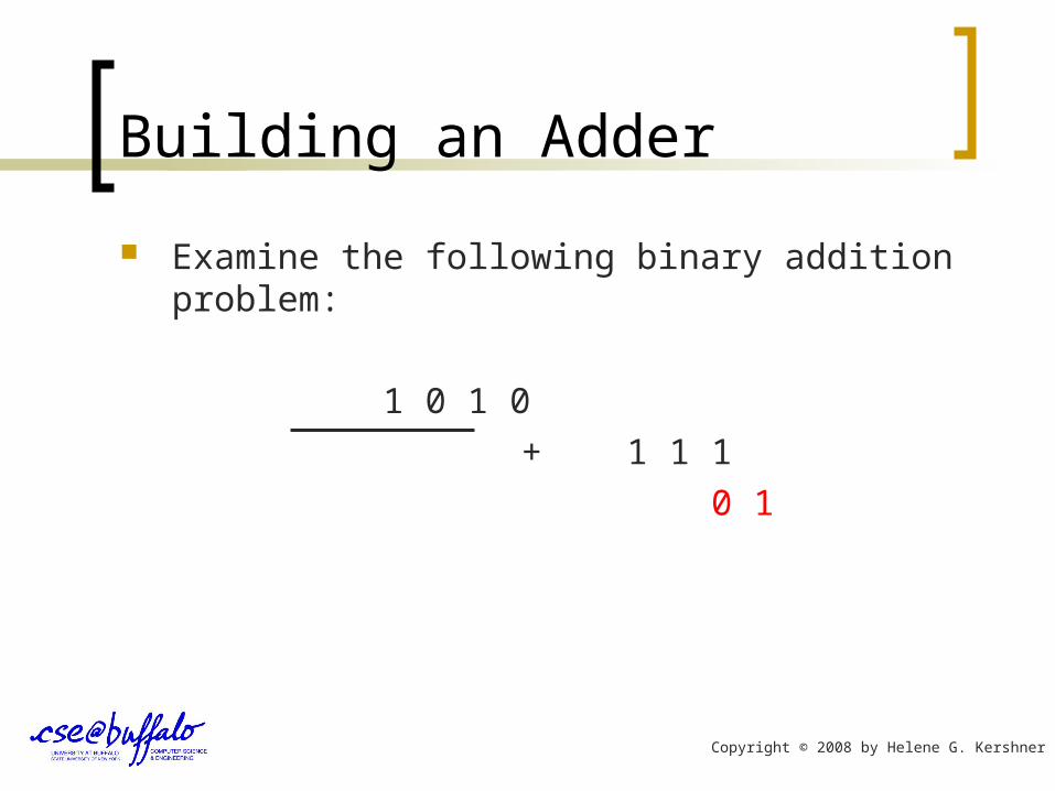
Examine the following binary addition problem:
1 0 1 0
+ 1 1 1
0 1
Copyright © 2008 by Helene G. Kershner

Building an Adder
Examine the following binary addition problem:
1
1 0 1 0
+ 1 1 1
0 1
Copyright © 2008 by Helene G. Kershner

Building an Adder
Examine the following binary addition problem:
1 1
1 0 1 0
+ 1 1 1
0 0 1
Copyright © 2008 by Helene G. Kershner
Building an Adder
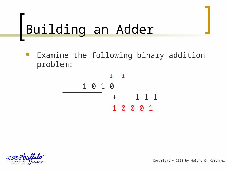
Examine the following binary addition problem:
1 1
1 0 1 0
+ 1 1 1
1 0 0 0 1
Copyright © 2008 by Helene G. Kershner

Building an Adder
When reviewing the example, the addition is not quite as simple as A + B = Sum.
In many cases a “carry” impacts our addition.
1 0 1 0
+ 1 1 1
10 1
Copyright © 2008 by Helene G. Kershner
Building an Adder
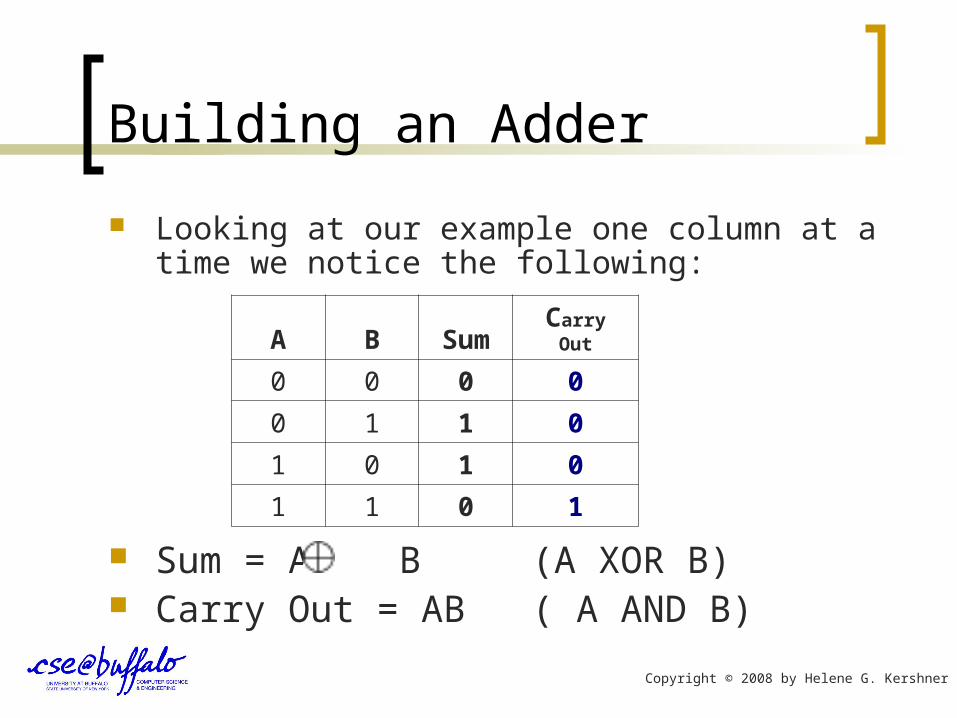
Looking at our example one column at a time we notice the following:
Sum = A B (A XOR B) Carry Out = AB ( A AND B)
A B SumCarry
Out
0 0 0 0
0 1 1 0
1 0 1 0
1 1 0 1
Copyright © 2008 by Helene G. Kershner
Building an Adder
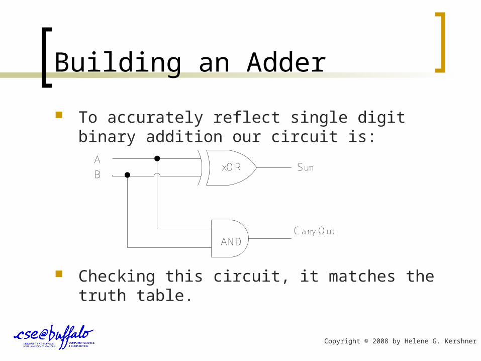
To accurately reflect single digit binary addition our circuit is:
Checking this circuit, it matches the truth table.
A
BSum
Carry Out
xOR
AND
Copyright © 2008 by Helene G. Kershner

Building an Adder
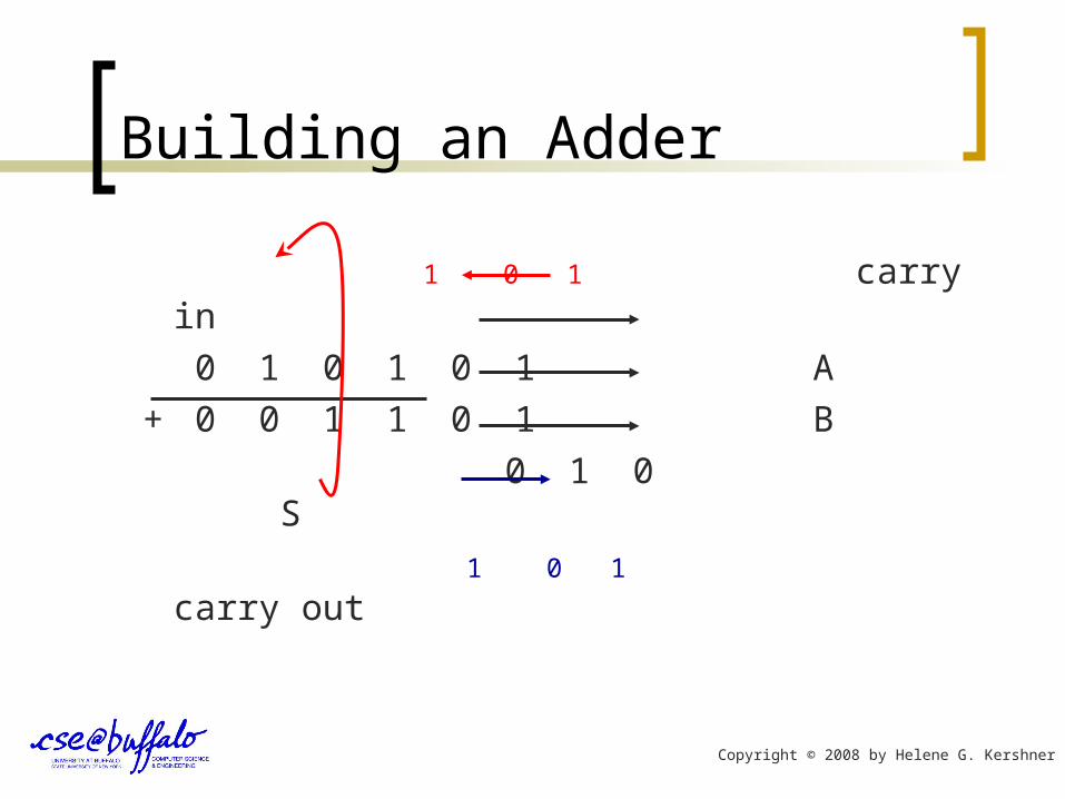
This is still not quite accurate. Going back to our binary addition problem, we find
that in reality we are not adding two bits, and getting a two bit answer.
Rather, our Carry Out from one column become the Carry In to the next column.
Copyright © 2008 by Helene G. Kershner

Building an Adder
1 carry in
0 1 0 1 0 1 A
+ 0 0 1 1 0 1 B
0 S
1 carry out
Copyright © 2008 by Helene G. Kershner
Building an Adder
0 1 carry in
0 1 0 1 0 1 A
+ 0 0 1 1 0 1 B
1 0 S
0 1 carry out
Copyright © 2008 by Helene G. Kershner
Building an Adder
1 0 1 carry in
0 1 0 1 0 1 A
+ 0 0 1 1 0 1 B
0 1 0 S
1 0 1 carry out
Copyright © 2008 by Helene G. Kershner
Building an Adder
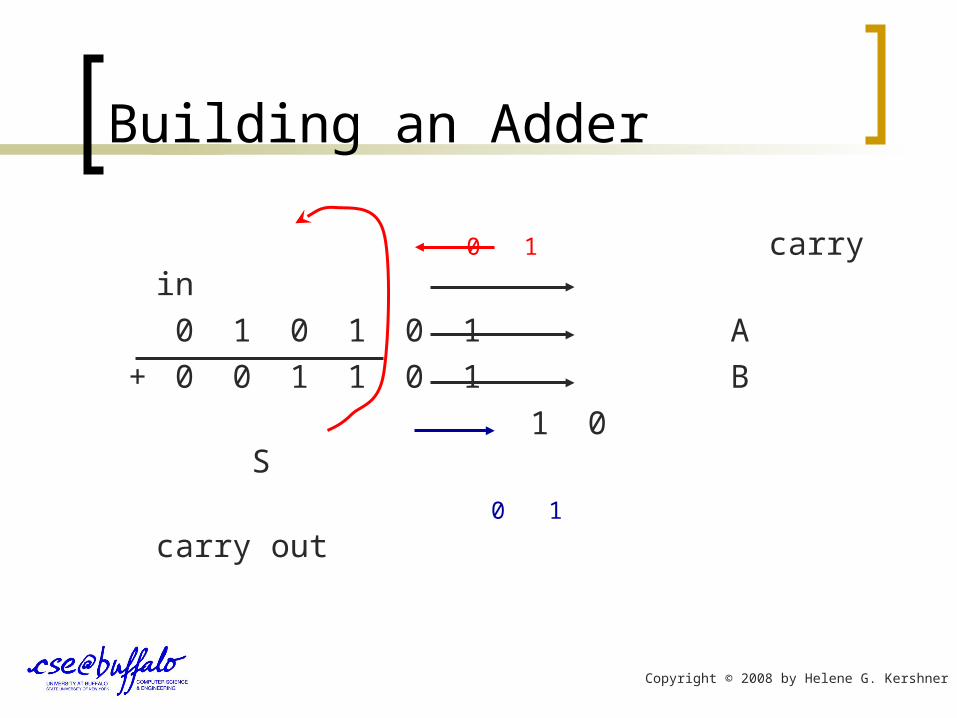
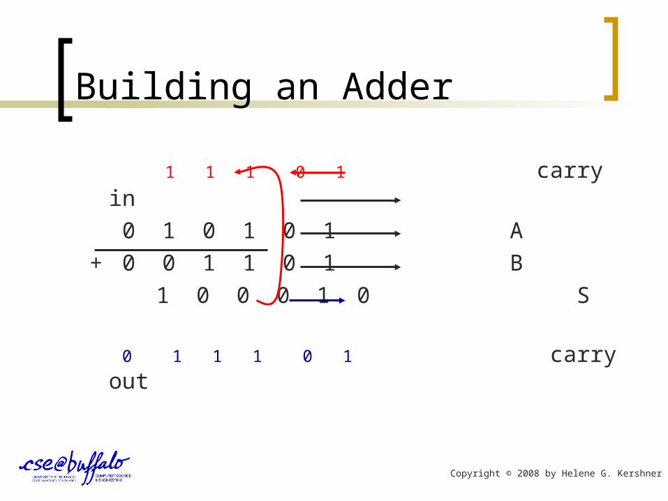
1 1 1 0 1 carry in
0 1 0 1 0 1 A
+ 0 0 1 1 0 1 B
1 0 0 0 1 0 S
0 1 1 1 0 1 carry out
Copyright © 2008 by Helene G. Kershner
Building an Adder
Adding two 1-bit numbers together turns out to really require that we add 3-bits together (including our Carry In) and producing an answer that is 2-bits (including our carry out).
A complete or “full” adder 3-bits, Cin, A, B and produces a Sum and a Carry Out.
Copyright © 2008 by Helene G. Kershner
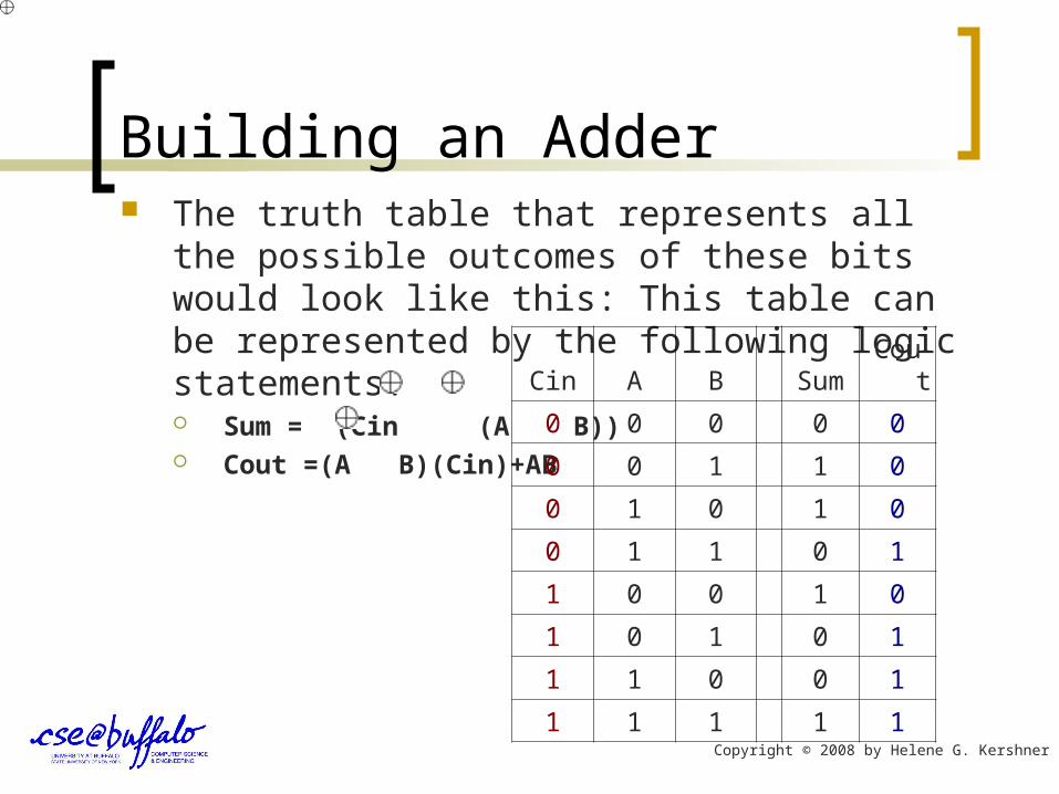
Building an Adder The truth table that represents all the possible
outcomes of these bits would look like this: This table can be represented by the following logic statements: Sum = (Cin (A B)) Cout =(A B)(Cin)+AB
Cin A B Sum Cout
0 0 0 0 0
0 0 1 1 0
0 1 0 1 0
0 1 1 0 1
1 0 0 1 0
1 0 1 0 1
1 1 0 0 1
1 1 1 1 1
Copyright © 2008 by Helene G. Kershner

Building an Adder
The circuit that represents this truth table, is called a Full Adder.
A
B
Sum (Half Adder 1)
Carry Out
(Half Adder 1)
XOR
AND
CinXOR
AND
OR
Sum
Carry Out
Half Adder (1) Half Adder (2)
Carry Out
(Half Adder 2)
Copyright © 2008 by Helene G. Kershner

Building an Adder
Another way to look at this is:
Half Adder (1)
Half Adder (2) Sum (Half Adder 1)
Cin
A
B
OR
Sum
Carry Out/Carry In
Copyright © 2008 by Helene G. Kershner

Building an Adder
A Full Adder then looks like this:
Half Adder (1)
Half Adder (2) Sum (Half Adder 1)
Cin
A
B
OR
Sum
Carry Out/Carry In
Full Binary Adder
Copyright © 2008 by Helene G. Kershner
Building an Adder
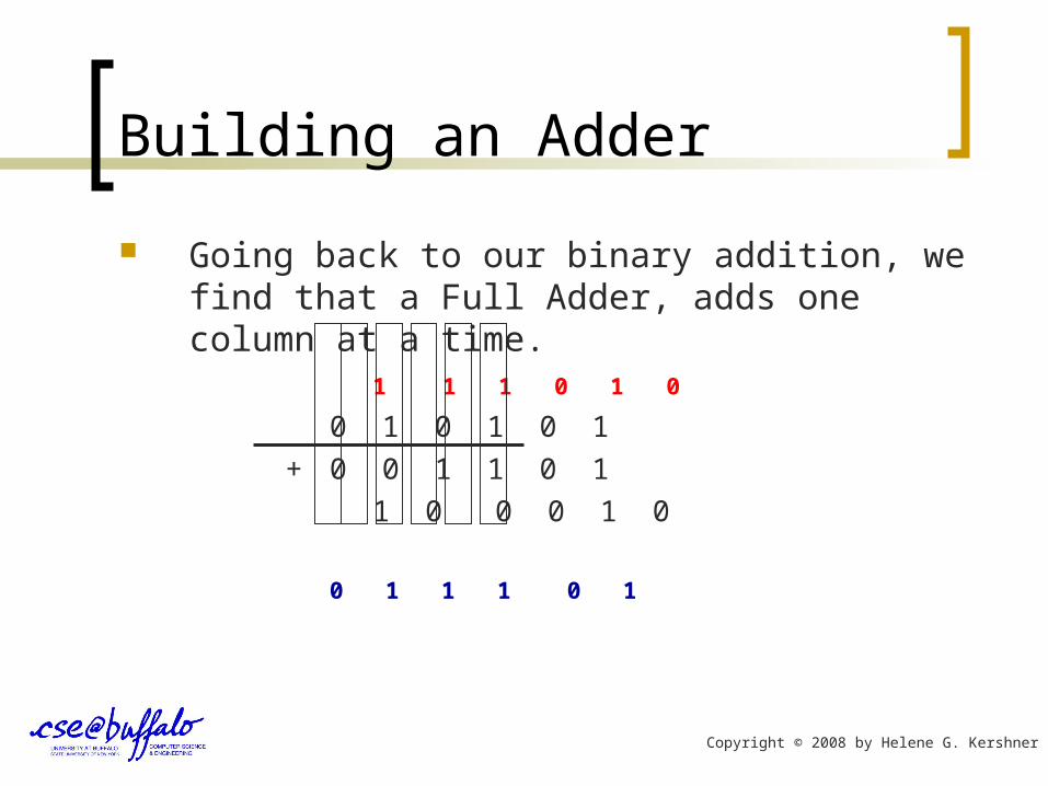
Going back to our binary addition, we find that a Full Adder, adds one column at a time.
1 1 1 0 1 0
0 1 0 1 0 1
+ 0 0 1 1 0 1
1 0 0 0 1 0
0 1 1 1 0 1
Copyright © 2008 by Helene G. Kershner
Building an Adder
To perform real binary addition, a series of binary adders are linked together.
The number of linked adders is determined by the manufacturer and reflects the finite-length a particular computer can handle.
This is usually, 8-bits, 16-bits, 32-bits or more.
Copyright © 2008 by Helene G. Kershner
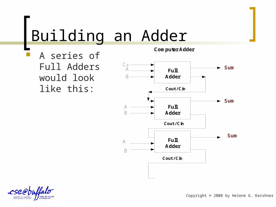
Building an Adder A series of Full
Adders would look like this:
CinA
B
Sum
Sum
Sum
Cout / Cin
Cout / Cin
Cout / Cin
A
A
B
B
Full Adder
Full Adder
Full Adder
Computer Adder
Copyright © 2008 by Helene G. Kershner