building a cisco ip fabric - grass valley home · 2017-07-21 · building a cisco ip fabric chris...
TRANSCRIPT

Building a Cisco IP FabricChris Merrill, Senior Product Manager Infrastructure, Strategic Marketing Alexandre Gagne, Senior Product Manager, Monitoring & Control, Strategic Marketing July 2017

WHITEPAPER BUILDING A CISCO IP FABRIC
2www.grassvalley.com
TABLE OF
CONTENTS
3.Introduction
3. COTS vs Proprietary Solution3. Building an IP Fabric with Cisco Products3. Why Buy from Grass Valley?
Building Blocks3. Switches4. SFPs and QSFPs
6.Cisco Data Center Network Manager 10 (DCMN 10)
7. PTPArchitecting a Non-blocking System
8. Vertically Accurate Switching8. Redundancy8. Control
9.Glossary of IP Standards Used in an IP Fabric
AES-67AMWA NMOS IS-04SMPTE ST 2022SMPTE ST 2022-6SMPTE ST 2022-7SMPTE ST 2110VSF TR-03VSF TR-04

WHITEPAPER BUILDING A CISCO IP FABRIC
3www.grassvalley.com
COTS vs Proprietary Solution
There are a variety of IP solutions for broadcast on the market today. They can be simplified into two main camps: Proprietary and Commer-cial off-the-Shelf (COTS). The four major trends leading to decreased usage of proprietary software are (1) faster development time, (2) more complex projects, (3) ease of use and predictability, and (4) the desire of senior management to avoid risks and to focus on core competen-cies. All four of those trends are present in today’s broadcast market.
While either a proprietary or a COTS solution can help you transition to UHD, a COTS solution that builds on existing data center models provides:
1. Infrastructure scalability
2. Ability to implement new services more quickly
3. Remote production
4. Ability to distribute content in multiple formats
5. Long-term lower ROI for processing costs based on Moore’s Law
In light of the advantages to our customers as discussed above, Grass Valley has chosen to innovate around a COTS IP core.
Grass Valley is actively qualifying COTS vendors. In this paper we will address a COTS solution based on Cisco switches.
Building an IP Fabric with Cisco Products
Cisco’s IP fabric for media solution uses Cisco Nexus 9200/9300-EX and 9508 platform switches in conjunction with the Cisco non-block-ing multicast (NBM) algorithm (an intelligent traffic management algo-rithm). By incorporating a variety of switches into the IP fabric, Cisco
is able to support either a fixed, single switch design or a flexible spine and leaf architecture in a reliable, scalable IP fabric for the broadcast industry. In addition, this IP fabric solution provides zero-drop multi-cast transport and support for PTP media profiles.
When discussing the architecture of an IP fabric, keep in mind that an IP Fabric based on a particular vendor’s products is not generic. Al-though Grass Valley works with other IP switch vendors, it should not be assumed that another vendor’s products may be easily substituted into the architecture described in this white paper. Each switch vendor has its own recommended architecture and products that are required to create a zero-drop, non-blocking multicast fabric.
For more information on Cisco-based solutions, see the following Cisco collateral: IP fabric for media release notes, solution guide, and video.
Why Buy from Grass Valley?
An IP network for media is different from a standard IP network. The overall architecture of the system is different, and Cisco switches must be appropriately licensed and provisioned with the correct algorithms. While we are working hard to educate Cisco resellers on the require-ments for broadcast and other media installations, most resellers still do not understand the requirements to create a non-blocking multi-cast system for media. To ensure qualified systems, Grass Valley has entered into an STI Partnership with Cisco that allows Grass Valley to sell or license products and services from Cisco as part of Grass Val-ley solutions. Customers who wish to source their own switches with-out oversight from Grass Valley do so at their own risk. Grass Valley will not be responsible for negotiating exchanges of network switches ordered by a customer that are inappropriately ordered or provisioned.
Building Blocks
Switches
The Nexus 9200, 9300 and 9500 series of switches from Cisco are currently the only switches with the correct Non-Blocking Multicast (NBM) algorithm (Cisco NX-OS Release 7.0(3)I4(2) or later) required to create a zero-drop, non-blocking multicast network for media. In these series, the models shown below best meet the need of the Grass Valley Broadcast Data Center solution.
Commercial Reference Description
N9K-C9236C CISCO switch with ports 36X100G QSFP28 breakable to 4X10/25G
N9K-C9272Q CISCO switch with ports 35 QSFP+ breakable to 4X10G and 37X40G
N9K-C92160YC-X CISCO switch with ports 48X10G QSFP+ and 2X50G and 4X40/100G
N9K-C93180YC-EX CISCO switch with ports 48X10/25G SFP+ and 6X40/100G QSFP28
N9K-C9508 Nexus 9508 Chassis with 8 linecard slots. Note that this platform is modular and must be provisioned with the correct number of Fabric Modules and Linecards.
Table 1: Cisco switch part numbers.
Notes:
• There is an earlier generation of the Nexus 9000 with a third-party ASIC. These switches will NOT work for Grass Valley’s Broadcast Data Center solution. Newer model switches with a Cisco ASIC are required.
• The part numbers shown above are base part numbers and do not include all licenses required to create a fully functioning switch.
• GV Node requires 40 Gb/s ports that break out to 4 x 10G. The N9K-C9272Q has only 35 ports that breakout to 4 x 10 Gb/s, while the N9K-C9236C has 36 ports that break out to 4 x 10G. The correct switch to use depends on the overall system architecture.
• Most designs using GV Node will use N9K-C9236C or N9K-C9272Q switches. Some designs using IPGs can use the Nexus N9K-C92160YC-X or 93180XY-EX as an alternative.
• Where possible, an architecture that takes advantage of the N9K-C9236C ability to aggregate data flows into 100 Gb/s uplinks between leaf and spine will result in fewer cables and potentially lower cost.
• Cisco’s IP Fabric for Media is not supported on all versions of 9500 linecards.

WHITEPAPER BUILDING A CISCO IP FABRIC
4www.grassvalley.com
SFPs and QSFPs
Small Form-factor Pluggable (SFP) interface converters and Quad Small Form-factor Pluggable (QSFP) interface converters, also known as transceivers provide the interface required for connecting equip-ment within an IP network. The transceivers are hot-swappable input/output (I/O) devices that connect a device’s ports with either a copper or a fiber-optic network cable. Each active port on a connected device such as GV Node or a network switch must have an SFP or QSFP to re-ceive and transmit audio or video data flows. Among other factors, the choice of which SFP or QSFP to use depends on bandwidth required by the data flows and distance the signal must travel (see Table 2).
DAC — Direct Attach Copper vs AOC — Active Optical Cable SFPs
Direct Attach Copper (also called passive) SFPs are generally less expensive than Active Optical Cable SFPs. In a large system, this can make a notable difference in the total price. However, there are tradeoffs in selecting DAC vs AOC SFPs.
Direct Attach Copper
While we have not done exhaustive testing of all DAC SFPs, the gen-eral performance of these SFPs has a much higher rate of signal deg-radation and dropped packets than comparable AOC SFPs. DAC ca-ble is bulky and vulnerable to electromagnetic interference. The cable is also limited to a maximum bandwidth of 40 Gb/s. We will continue to test DAC options but at the moment we do not recommend DAC SFPs for use between Cisco switches.
Active Optical Cable
AOC consist of multimode optical fiber, fiber optic transceivers, control chip and modules. It uses electrical-to-optical conversion on the cable ends to improve speed and distance performance of the cable without sacrificing compatibility with standard electrical interfaces. Compared with DAC for data transmission, AOC provides lighter weight, higher performance, lower power consumption, lower interconnection loss, EMI immunity and flexibility. All SFPs currently recommended for use between Cisco switches are AOC. LC and MPO transceivers with the appropriate fiber optic cable may also be used per the manufacturer’s specifications.
Transceiver LC
Transceiver MPO
Direct-AttachActive Optical Cable
WHITEPAPER BUILDING A CISCO IP FABRIC
5www.grassvalley.com
Commercial Reference Description
QSFP-100G-AOC10M= 100 GBASE QSFP Active Optical Cable, 10m
QSFP-100G-AOC15M 100 GBASE QSFP Active Optical Cable, 15m
QSFP-100G-AOC1M 100 GBASE QSFP Active Optical Cable, 1m
QSFP-100G-AOC2M 100 GBASE QSFP Active Optical Cable, 2m
QSFP-100G-AOC3M 100 GBASE QSFP Active Optical Cable, 3m
QSFP-100G-AOC5M 100 GBASE QSFP Active Optical Cable, 5m
QSFP-100G-AOC7M 100 GBASE QSFP Active Optical Cable, 7m
QSFP-100G-CWDM4-S= 100 GBASE CWDM4 QSFP Transceiver, LC, 2 km over SMF
QSFP-100G-LR4-S= 100 GBASE LR4 QSFP Transceiver, LC, 10 km over SMF
QSFP-100G-SR4-S= 100 GBASE SR4 QSFP Transceiver, MPO, 100m over OM4 MMF
QSFP-4SFP25G-CU3M= 100 GBase QSFP to 4xSFP25G Passive Copper Splitter Cable, 3m
QSFP-40G-BD-RX= QSFP40G Bidirectional Short-reach Transceiver, RX
QSFP-40G-CSR4= QSFP 4x10 GBASE-SR Transceiver Module, MPO, 300m
QSFP-40GE-LR4= QSFP 40 GBASE-LR4 Transceiver Module, LC, 10 km
QSFP-40G-ER4= QSFP 40 GBASE-ER4 Transceiver Module, LC, 40 km
QSFP-40G-LR4= QSFP 40 GBASE-LR4 OTN Transceiver, LC, 10 km
QSFP-40G-LR4-S= QSFP 40 GBASE-LR4 Transceiver Module, LC, 10 km, Enterprise-class
QSFP-40G-SR4= 40 GBASE-SR4 QSFP Transceiver Module with MPO Connector
QSFP-40G-SR4-S= 40 GBASE-SR4 QSFP Transceiver Module, MPO Connector, Enterprise-class
QSFP-40G-SR-BD= QSFP40G Bidirectional Short-reach Transceiver
QSFP-4X10G-AOC7M= 40 GBASE Active Optical QSFP to 4SFP Breakout Cable, 7m
QSFP-4X10G-LR-S= QSFP 4x10G Transceiver Module, SM MPO, 10 km, Enterprise-class
QSFP-H40G-AOC10M= 40 GBASE Active Optical Cable, 10m
QSFP-H40G-AOC15M= 40 GBASE Active Optical Cable, 15m
QSFP-H40G-AOC1M= 40 GBASE Active Optical Cable, 1m
QSFP-H40G-AOC2M= 40 GBASE Active Optical Cable, 2m
QSFP-H40G-AOC3M= 40 GBASE Active Optical Cable, 3m
QSFP-H40G-AOC5M= 40 GBASE Active Optical Cable, 5m
QSFP-H40G-AOC7M= 40 GBASE Active Optical Cable, 7m
SFP-10G-LR 10 GBASE-LR SFP Module
SFP-10G-SR 10 GBASE-SR SFP Module
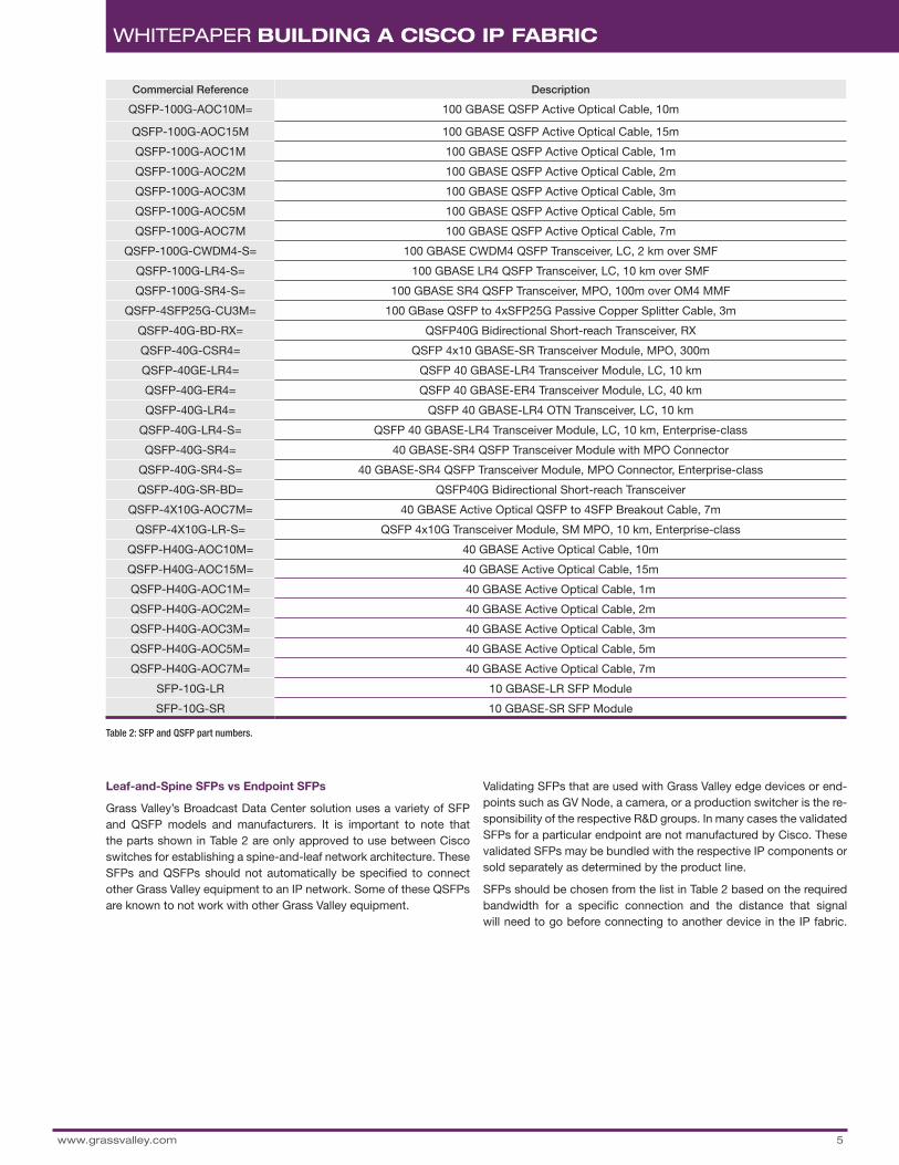
Table 2: SFP and QSFP part numbers.
Leaf-and-Spine SFPs vs Endpoint SFPs
Grass Valley’s Broadcast Data Center solution uses a variety of SFP and QSFP models and manufacturers. It is important to note that the parts shown in Table 2 are only approved to use between Cisco switches for establishing a spine-and-leaf network architecture. These SFPs and QSFPs should not automatically be specified to connect other Grass Valley equipment to an IP network. Some of these QSFPs are known to not work with other Grass Valley equipment.
Validating SFPs that are used with Grass Valley edge devices or end-points such as GV Node, a camera, or a production switcher is the re-sponsibility of the respective R&D groups. In many cases the validated SFPs for a particular endpoint are not manufactured by Cisco. These validated SFPs may be bundled with the respective IP components or sold separately as determined by the product line.
SFPs should be chosen from the list in Table 2 based on the required bandwidth for a specific connection and the distance that signal will need to go before connecting to another device in the IP fabric.

WHITEPAPER BUILDING A CISCO IP FABRIC
6www.grassvalley.com
Cisco Data Center Network Manager 10 (DCMN 10)Cisco Data Center Network Manager 10 (DCMN 10) software provides an advanced network management system for an IP fabric based on a Cisco Nexus switch infrastructure. Key features that DCNM provides in Grass Valley’s Broadcast Data Center solution include:
• Authorizing endpoints and flows
• Managing audio, video, and ancillary data flows of varying band-width. Without the DCNM, bandwidth must be allocated at the same fixed rate for every flow in the fabric
• Managing non-drop flows across multiple spines
• Interface to GV Convergent
• Providing flow statistics
• A fabric using DCNM requires a server with a Data Center Network Manager server license and an advanced feature license for each switch in the fabric
Web browsers that support HTML5 are qualified for use with Data Center Network Manager 10, including Internet Explorer, Firefox, Sa-fari and Chrome.
Note: A single switch configuration (directly connected endpoints with no leaf switches) such as a standalone 9508 topology does not require DCNM to manage flow sizes or non-drop, but it does require DCNM to have the other features shown above for Host Policy and interface to GV Convergent.
To add DCNM to a fabric:
Step 1: Select a server.
Although DCNM will support larger deployments, most Broadcast Data Center solutions will be a small deployment based on the server resource requirements shown below for deploying the Data Center Network Manager 10 ISO virtual appliance.
Small Deployment: Up to 50 Switches
Commercial Reference Description
UCSC-C240-M4S UCS C240 M4 SFF 8 HD w/o expdr, CPU, mem, HD, PCIe, PS, railkt
UCSC-MRAID12G-1GB Cisco 12 Gb/s SAS 1 GB FBWC Cache module (RAID 0/1/5/6)
Table 3: DCNM server requirements.
Step 2: Add a base license for the server.
The majority of Broadcast Data Center fabrics will use the license shown below. The license is installed on the Data Center Network Manager server.
Commercial Reference Description
DCNM-SVR-10-K9 Base DCNM Server — DVD
Step 3: Add an advanced feature license for each switch in the fabric.
A license must be installed on the server for each switch in the fabric — regardless of whether the switch is functioning as leaf or spine. Licens-es should be chosen according to the series of switch that they support.
Part Number Description
DCNM-LAN-N95-K9 DCNM for LAN Advanced Edt. for Nexus 9500 switches
DCNM-LAN-N93-K9 DCNM for LAN Advanced Edt. for Nexus 9300 switches
DCNM-LAN-N92-K9 DCNM for LAN Advanced Edt. for Nexus 9200 switches
Example
An IP fabric topology with two spines and six leafs based on N9272 would have the following bill of materials for DCNM.
Qty Part Number Description
1 UCSC-240-M4S UCS C240 M4 SFF w/o CPU, mem, HD, PCIe, w/ rail kit, expdr
1 UCSC-MRAID12G-1GB Cisco 12 Gb/s SAS 1 GB FBWC Cache module (RAID 0/1/5/6)
1 DCNM-SVR-10-K9 Base DCNM Server — DVD
8 DCNM-LAN-N92-K9 DCNM for LAN Advanced Edt. for Nexus 9200 switches
Additional information on Cisco DCNM v10 may be found in the Cisco DCNM datasheet.

WHITEPAPER BUILDING A CISCO IP FABRIC
7www.grassvalley.com
Figure 1: Non-blocking spine-leaf architecture.
PTPThe Precision Time Protocol (PTP) is used to synchronize clocks for all devices in the Broadcast Data Center. In a spine-leaf configuration, the “grandmaster clock” generates system time. “Boundary clocks” may be slaved to the grandmaster. All devices that use the same grandmaster must reside in the same network domain.
Note: While PTP also has a transparent clock option, Cisco supports boundary clock only. PTP is not supported on 9508-R line cards prior to October 2017
Architecting a Non-blocking System
N9K-C9272Q/ 12 / / 12 / N9K-C9272Q
N9K-C9272Q
/ 12 / / 12 / N9K-C9272Q/ 12 / / 12 /
/ 24 // 24 / / 24 /
Spine
Leaf
Endpoint
Spine and Leaf
In spine-leaf architecture, the leaf layer consists of access switches that connect to endpoints such as GV Node, a camera or a produc-tion switcher. The spine layer is the backbone of the network and is responsible for interconnecting all leaf switches. A spine switch does not connect directly to another spine. Even when there are multiple spines, every leaf switch is connected to each of the spine switches.
Edge Device or Endpoint
Unlike switches which manage the join and leave patterns for flows, an edge device, also known as an endpoint, is something that eats or makes flows (video, audio and/or ancillary data). Most of the equip-ment Grass Valley manufactures for the Broadcast Data Center is an endpoint.
Design Rules
Figure 2: Balancing bandwidth between spine and leaf.
N9K-C9236C N9K-C9236C
N9K-C9236C
N9K-C9236C
Spine
Leaf
Endpoint
/ 12x40G / / 12x40G / / 12x40G / / 12x40G / / 12x40G / / 12x40G /
/ 10x100G / / 10x100G / / 10x100G /
Figure 2: Balancing bandwidth between leaf and spine

WHITEPAPER BUILDING A CISCO IP FABRIC
8www.grassvalley.com
To create a fully non-blocking system the following design rules should be observed:
• As shown in Figure 2, the total bandwidth between a spine switch and a leaf switch must be greater than or equal to the total band-width between a leaf switch and the endpoint(s). Note that band-width is the size of the data flows, not the number of ports.
• Where possible, use of the higher bandwidth ports for flow aggre-gation in the N9K-C9236C will result in fewer cables and potentially lower cost.
• Requirement for breakout ports must match the requirement of the connected device.
• 8000 simultaneous routes is the current limit of Cisco software for the 9200 series.
• 32,000 simultaneous routes is the limit of the fabric when using the 9508 switch.
• Balance leaves so that not all input sources are on a single leaf in a multiple leaf system.
• All devices that rely on the same PTP must reside in the same net-
work domain.
Vertically Accurate Switching
In an IP fabric, vertically accurate switching is accomplished by joining the new flow that is selected before dropping the previous flow in a join-before-leave switch. To accomplish a seamless join-before-leave switch, the IP fabric must have enough available bandwidth to con-nect both flows before one is dropped.
If the network infrastructure is redundant, then the additional band-width required for redundancy can be used to achieve join-before-leave. If the network infrastructure is not redundant then free band-width between the leaf and endpoint(s) needs to be reserved. For example, a studio where every flow was switched in a salvo at the top of the hour would require double the amount of bandwidth between leaf and endpoint (e.g., six 10 Gb/s flows would require 120 Gb/s of non-blocking network bandwidth).
Normally, not all flows sent to a fabric require a vertically accurate switch. However, overall bandwidth allocation should be reviewed and approved by the Sales Engineering team as part of a system design.
Redundancy
While it is possible to achieve some redundancy in other ways, the preferred method is to create two identical and completely independent IP fabrics that connect to endpoints that function according to SMPTE ST 2022-7. As shown in Figure 3, the connections between these inde-pendent fabrics take place at the endpoint with duplicate cables going to each fabric. There is no other connection between the two fabrics. Both fabrics send duplicate streams to the endpoint. The endpoint then determines from the parallel data flows which packet is the best to use.
Figure 3: Redundant system architecture.
Control
Control of a Broadcast Data Center is a collaboration between GV Convergent and Cisco DCNM. Cisco DCNM manages the IP fabric. GV Convergent interfaces with DCNM and also with the endpoints such as GV Node or the Densité IPG to control the entire Broadcast Data Center solution.
N9K-C9272Q
N9K-C9272Q
N9K-C9272Q
/ 6 x 40G /
N9K-C9272Q
N9K-C9272Q
N9K-C9272Q
/ 6 x 40G /
/ 6 x 40G /
/ 6 x 40G /
/ 6 x 40G /
/ 6 x 40G /
/ 35 x 40G /
/ 35 x 40G /
/ 35 x 40G /
/ 35 x 40G / / 6 x 40G /
/ 6 x 40G /
/ 6 x 40G /
/ 6 x 40G /
/ 5 x 40G /
/ 6 x 40G /
/ 6 x 40G /
/ 6 x 40G /
/ 6 x 40G /
/ 6 x 40G /
/ 5 x 40G /
/ 6 x 40G /
/ 6 x 40G /
/ 6 x 40G /
/ 6 x 40G /
/ 6 x 40G /
/ 5 x 40G /
/ 6 x 40G /
/ 5 x 40G /
DCNMDCNM
Fabric A Fabric B

WWW.GRASSVALLEY.COMJoin the Conversation at GrassValleyLive on Facebook, Twitter, YouTube and Grass Valley - A Belden Brand on LinkedIn.
9
WHITEPAPER BUILDING A CISCO IP FABRIC
GVB-1-0620C-EN-WP
Belden, Belden Sending All The Right Signals and the Belden logo are trademarks or registered trademarks of Belden Inc. or its affiliated companies in the United States and other jurisdictions. Grass Valley, GV Convergent and GV Node are trade-marks or registered trademarks of Grass Valley Canada. Belden Inc., Grass Valley Canada and other parties may also have trademark rights in other terms used herein.
Copyright © 2016-2017 Grass Valley Canada. All rights reserved. Specifications subject to change without notice.
Glossary of IP Standards Used in an IP Fabric
AES-67
Developed by the Audio Engineering Society, AES-67 is the most widely accepted standard for audio-over-IP interoperability. The audio flows in VSF TR-03 and TR-04 are AES-67 compliant. AES-67 is a lay-er 3 protocol suite based on existing standards and allows interop-erability between previously competing audio-over-IP systems such as RAVENNA, Livewire, Q-LAN and Dante. It also identifies common-alities with Audio Video Bridging (AVB) and documents AVB interop-erability scenarios.
AMWA NMOS IS-04
Network Media Open Specifications (NMOS) is a family name for open source specifications produced by the Advanced Media Workflow As-sociation related to networked media for professional applications. The Discovery and Registration Specification (IS-04) enables discov-ery and registration of the parts of the system in a vendor-neutral way, catalogs the streams being generated, and provides minimal endpoint control.
SMPTE ST 2022
SMPTE ST 2022 is a standard from the Society of Motion Picture and Television Engineers (SMPTE) that describes how to send digital vid-eo over an IP network. The standard is published in seven parts.
SMPTE ST 2022-6
This standard specifies a way to transport high bit-rate media signals, including uncompressed 3 Gb/s 1080p video, over IP networks.
SMPTE ST 2022-7
Required for system redundancy, this standard for seamless protec-tion switching of SMPTE ST 2022 IP datagrams describes a way to send two matching streams of packets from a source to an endpoint over different paths, and have the receiver switch automatically be-tween them. This allows a perfect video signal to be reconstructed at the receiver as long as both paths do not fail simultaneously.
SMPTE ST 2110
Currently in draft stage, this is the SMPTE designation which will in-clude protocols comparable to the VSF TR-03 and TR-04 standards to transport separate audio and video essences over IP networks.
VSF TR-03
Video Services Forum Technical Recommendation 03 provides for the carriage of video, audio and ancillary data as separate elementary streams or essences that can be individually forwarded through an IP network. Audio, video and ancillary data are separate streams multi-plexed with PTP to keep them in sync. Sending individual essences allows data flows to be targeted to the specific endpoints that require it while reducing overall bandwidth requirements for the IP fabric.
VSF TR-04
Video Services Forum Technical Recommendation 04 builds upon the system defined in VSF TR-03 by adding SMPTE ST 2022-6 as a video payload. The resulting method allows for the SDI multiplex, as well as the individual audio and metadata streams, to be individually forward-ed through a network. This protocol works well in production environ-ments that require both ST 2022-6 compatibility and separate audio.