bu kitabın baskı versiyonu bildirilerin tam metinlerini
TRANSCRIPT

Bu kitabın baskı versiyonu bildirilerin tam metinlerini içermektedir. E-kitaba
www.uludag.edu.tr/ulpas adresinden ulaşılabilir.
This printed book contains the full texts of the papers presented at the symposium. The pdf
version of the Book of Proceedings can be downloaded from the website
www.uludag.edu.tr/ulpas.

Ocak 2020
Editörler
Prof. Dr. Yusuf ULCAY
Prof. Dr. Ali DEMİR
Doç. Dr. Ali KILIÇ
Dr. Öğretim Üyesi Şule SELÇUK
Uluslararası Lif ve Polimer Araştırmaları Sempozyumu (1: 2020: Bursa)
6. Uluslararası Lif ve Polimer Araştırmaları Sempozyumu: 24 – 25 Ocak 2020 / editörler
Yusuf Ulcay, Ali Demir … [ve başkaları]
1.Tekstil lifleri-Türkiye-Kongreler 2.Polimerler-Türkiye-Kongreler
Bilim Komitesi / Scientific Committee
Prof. Dr. Yusuf ULCAY, Bursa Uludağ Üniversitesi
Prof. Dr. Ali DEMİR, İTÜ
Prof. Dr. Behnam POURDEYHIMI, NCSU, USA
Prof. Dr. Mohammad JAWAID, UPM, Malaysia
Prof. Dr. Seyed Ali MOUSAVI SHAEGH, MUMS, İRAN
Prof. Dr. Ömer Berk BERKALP, İTÜ
Prof. Dr. Kenan YILDIRIM, BTÜ
Prof. Dr. Hasan Basri KOÇER, BTÜ
Prof. Dr. Mehmet KANIK, Bursa Uludağ Üniversitesi
Prof. Dr. Esra KARACA, Bursa Uludağ Üniversitesi
Prof. Dr. Aslı HOCKENBERGER, Bursa Uludağ Üniversitesi
Prof. Dr. Gökhan GÖKTALAY, Bursa Uludağ Üniversitesi
Prof. Dr. Asım OLGUN, Bursa Uludağ Üniversitesi
Prof. Dr. Mustafa Erdem ÜREYEN, Eskişehir Teknik Üniversitesi
Doç. Dr. Ali KILIÇ, İTÜ
Doç. Dr. Burhan COŞKUN, Bursa Uludağ Üniversitesi
Doç. Dr. Ayşe ÇELİK BEDELOĞLU, BTÜ
Doktora Öğretim Üyesi, Şule SELÇUK, İTÜ
Doç. Dr. Hüseyin AVCI, Eskişehir OGÜ
Assist. Prof. Dr. Tamer HAMOUDA, National Science Foundation, Egypt
Assist. Prof. Dr. Ahmed HASSANIN, Egypt Japan University, Egypt
Assist. Prof. Dr. Abdelrahman ABDELGAWAD, NCSU, USA
Pınar Taşdelen ENGİN, Polyteks-Bursa
Gülşen TARDÜ, Polyteks-Bursa

Organizasyon Komitesi / Organization Committee
Prof. Dr. Yusuf ULCAY, Bursa Uludağ Üniversitesi
Prof. Dr. Ali DEMİR, İTÜ
Prof. Dr. Behnam POURDEYHIMI, NCSU, USA
Prof. Dr. Mohammad JAWAID, UPM, Malaysia
Prof. Dr. Kenan YILDIRIM, BTÜ
Prof. Dr. Mustafa Erdem ÜREYEN, Eskişehir Teknik Üniversitesi
Doç. Dr. Ali KILIÇ, ITÜ
Doç. Dr. Ayşe ÇELİK BEDELOĞLU, BTÜ
Doç. Dr. Hüseyin AVCI, Eskişehir OGÜ
Doktora Öğretim Üyesi Şule SELÇUK, İTÜ
Assist. Prof. Dr. Tamer HAMOUDA, National Science Foundation, Egypt
Assist. Prof. Dr. Ahmed HASSANIN, Egypt Japan University, Egypt
Assist. Prof. Dr. Abdelrahman ABDELGAWAD, NCSU, USA
Dr. İsmail BORAZAN, Bartın Üniversitesi
Araş. Gör. Rumeysa ÇELEN, Bursa Uludağ Üniversitesi
Araş. Gör. Gizem MANASOĞLU, Bursa Uludağ Üniversitesi
Araş. Gör. Nazlı ARMAN, Bursa Uludağ Üniversitesi
Araş. Gör. Yasin ALTIN, BTÜ
Araş. Gör. Ahmet AYDIN, BTÜ
Araş. Gör. Fatma Nur PARIN, BTÜ
Tuğba BAYSAL, İTÜ
Ömer Fırat TURŞUCULAR, Bursa Uludağ Üniversitesi
Merve Nur SAĞIRLI, İTÜ TEMAG Lab


6. Uluslararası Lif ve Polimer Araştırmaları Sempozyumu (6.ULPAS)
3 Mayıs 2019'da İTÜ, Gümüşsuyu Yerleşkesinde 5. ULPAS’ı “Medikal Tekstiller” vurgusuyla
gerçekleştirdik. Böyle yapmamızın sebebi, bu sempozyumların ana unsurlarından birisi olan
İTÜ’de Tekstil Teknolojileri ve Tasarımı Fakültesinde 30 yıldır faaliyet gösteren “İTÜ
TEMAG Laboratuvarı”nın İstanbul Kalkınma Ajansı (İSTKA) destekli yürüttüğü bir proje olan
“TR10/18/YMP/0075-MEDİTEKS: Medikal tekstiller Ar-Ge Merkezi”nin kuruluş lansman
toplantısıyla birlikte gerçekleştirmekti. İyi de oldu. Sempozyum bu sayede daha farklı bir
kitleye daha erişti.
6. ULPAS’da “uluslararası sempozyum” vurgusu ile ve sponsorlarımızın destekleriyle tüm
dünyadan konularında öne çıkmış araştırmacıları davet ettik. Yurtdışından gelen bu
davetlilerimizi sempoyumda “Ana Konuşmacı” yaptık ve oturumları da aşağıdaki gibi konulara
göre düzenlemeye gayret ettik;
- Doku Mühendisliği - Medikal Tekstiller
- Nanoyapılar
- Nanolif Uygulamaları
- Nanolif Üretim Teknikleri – Electrospinning
- Kompozitler ve Doğal Elyaf Takviyetli Kompozitler
- Nonwovenlar
- Lif ve Tekstil Teknolojileri
Bu Bildiriler Kitabı sempozyum esnasında katılımcıların elinde olduğu gibi sempozyum
internet sayfası (www.uludag.edu.tr/ulpas) adresinden önceki sempozyumların bildiri kitapları
ile birlikte her zaman erişebilecektir.
6. Uluslararası Lif ve Polimer Araştırmaları Sempozyumu'nun da şimdiye kadar olduğu gibi
başarılı, katılımcılara için yararlı ve ülkemiz için katkı verici olacağına inancımız tamdır.
Lif ve Polimer Araştırmaları Enstitüsü adına
Prof. Dr. Yusuf ULCAY
Prof. Dr. Ali DEMİR

6th International Fiber and Polymer Research Symposium (6th IF&PRS)
On the 3rd May 2019, we have organised the 5th International Fiber and Polymer Research
Symposium (5th IF&PRS) at İTÜ, Gümüşsuyu Campus-Istanbul with an emphasis on “Medical
Textiles”. It was due to the fact that as the main components of these sysmposia, ITU TEMAG
Lab had the first announcement meeting for their reserach and developmet Project
“TR10/18/YMP/0075-MEDİTEKS: Medical Textiles R&D Center” supported by Istanbul
Develeopment Agency (ISTKA). It was a real success and the symposium had a chance to reach
a different audience.
As an international reserach and developemtn symposium, we have invited some distiguished
researchers in the field of fiber and polymers from all over the world with the the kind financial
support of our sponsors. Those internationally pionering names will be our “Keynote Spekers”
during the symposium. We have also divided the papers into subject groups as follws;
- Tissue Engineering - Medical Textiles
- Nanostructures
- Nanofiber Applications
- Nanofiber Production Techniques – Electrospinning
- Composites and Natural Fiber reinforced Composites.
- Nonwovens
- Fiber, Polymer and Textile Technologies.
The book of proceedings will be available in printed form during the sysmposium. It can alos
be accessed by the link (www.uludag.edu.tr/ulpas) together will all of the previous symposium
Book of Proceedings.
As we have experienced so far, we believe that this 6th IF&PRS will also be another success
story for all those who have attended as well as our beloved city for Istanbul as well as our
country.
On behalf of the Fiber and Polymer Research Institute
Prof. Dr. Yusuf ULCAY
Prof. Dr. Ali DEMİR

İÇİNDEKİLER
Biomimetic Approaches to Tissue Engineering of Organoids
AVCI, Huseyin……………………………………………………………………………….... 1
Bioactive Polypropylene Nonwovens via Immobilization of Proteins-embedded Silver
Nanoparticles
ABDELGAWAD, Abdelrahman, ROJAS, Orlando……………………………………………. 3
Biofunctionalization of hydrogels for tissue engineering applications
AVCI-ADALI, Meltem…………………………………………………………………………. 5
Biodegradable Polymers for Tissue Engineering
ARMAN, Nazlı, ULCAY, Yusuf………………………………………………………………... 6
Design and Development of a Personalized Medicine Oriented Microfluidic Organ on a
Chip Platform
KIZILKURTLU, Ahmet Akif, AKPEK, Ali…………………………………………………….. 8
Enhancement of Mechanical Properties of Poly(lactic acid) by Blending with Epoxidized
Natural Rubber
GUMUS, Omer Yunus, OZBAY, Ceren……………………………………………………… 11
Tıbbi Plaster Kumaşı Üretimi İçin İplik Haşıl Kriterlerinin Araştırılması ve Performans
Testleri
KOPTAGEL, Hüner, GÜRLER, Hale, TURGUT, Halil İbrahim……………………………. 13
Characterization Study of Drug Loaded PLA Electrospun Nanofibers
BARBAK, Zarife, KARAKAŞ Hale, SARAÇ, A.Sezai…………………………………………15
Photocatalytic Activities of ALD (Atomic Layer Deposition) TiO2 and ZnO films on
Glass Fabrics
ISLAM, Shafiqul, AKYILDIZ, Halil I………………………………………………………... 18
Immobilization of Cu-BTC on The Cotton Fibers For Sensor Applications
SAYGI, Gizem, ÇAKICIOĞLU ÖZKAN, Fehime, GÜNER, Cemal…………………………. 20
One-step preparation and characterization of a nanostructured hybrid electrode
material through a microwave energy-based approach
POYRAZ, Selçuk……………………………………………………………………………... 22
Production of Fibrous Gelatin Mat as Antibacterial Wound Dressing Material via
Centrifugal Spinning Method
GUNGOR, Melike, SAGIRLI, Merve Nur, CALISIR, D. Mehmet, KILIC, Ali………………. 26
Manufacture of Nanofibers: Current Status and Promising Developments
BORAZAN, İsmail, KAPLAN, Müslüm, ÜZÜMCÜ, Memik Bünyamin……………………… 28

Poliamid 6,6’nın Isıl İletkenliğinin Geliştirilmesinde Karbon Elyafın Etkisi
BEYAZ, Rumeysa, ÖKSÜZ, Mustafa………………………………………………………… 31
A Comparative Study of Silica Fibers Prepared by Solution Blowing (SB) and Electro-
Solution Blowing (ESB) Methods
CALISIR Mehmet D, GUNGOR Melike, KILIC Ali…………………………………………. 34
Antibakteriyel HEPA Filtrelerin Elektro Üfleme Yöntemi ile Üretimi
TOPTAŞ, Ali, AKGÜL, Yasin, GÜNGÖR, Melike, KILIÇ, Ali, DEMİR, Ali………………… 36
Grafen Katkılı Karbon Nanoliflerin Süperkapasitörlerde Kullanımı
ALTIN, Yasin, BEDELOĞLU, Ayşe…………………………………………………………. 40
Usage of Polyacrylonitrile Nanofibers Containing MgO Nanoparticles on Particulate
Filtration and Toluene Adsorption
DEMIR, Ali, BAYSAL, Tugba………………………………………………………………... 42
Interaction of Phosphate-Buffered Saline on the Surface of Carbon Nanofiber
Electrodes
SAHTANİ Karima, ALADAĞ TANİK Nilay, AYKUT Yakup………………………………… 45
Understanding the Electrospinnability of Polyvinyl Alcohol (PVA) and Controlled
Release of Curcumin Through the Electrospun Mat
MAHMUD, Md Musavvir, PARVEEN, Asma, ZAMAN, Sumaiya, JAHAN, Rumana A,
ARAFAT, M Tarik……………………………………………………………………………. 49
Nanolif Esaslı Piezoelektrik Nanojeneratörlerde Elektrosprey Yoluyla Elektrot
Uygulamaları
ÜNSAL, Ömer Faruk, ÇELİK BEDELOĞLU, Ayşe…………………………………………. 51
An Innovative Development Towards The Industrialization of Electrospinning Process -
Hybrid Electrospinning Technology
DEMİR, Ali, SAAT, Gülbahar, KESKİN, Yusuf, BÜLBÜL, Ertuğrul………………………... 54
Development of Self-healing EVA Films
SEZER HİÇYILMAZ, Ayşe, ÇELİK BEDELOĞLU, Ayşe…………………………………… 60
Potential of Ethiopian Enset Fiber for Textile Application
TEMESGEN, Alhayat G, TURŞUCULAR, Ömer F, EREN, Recep, AYKUT, Yakup………... 63
Thermal Insulation Properties of Glass Fiber Epoxy Composite with Stonewool Fiber,
Nanofiber Web, Silica Aerogel Layers
GÜNAL, Sevde Rana, SAYAR, Ersin, GEYGEL, Berkay, ÖZKAN HACIOĞULLARI, Selcen,
KARACA, Neslihan, UÇAR, Mehmet, SELVER, Erdem, SOLAK, Nuri, BAYDOĞAN, Murat,
ÖNEN, Ayşen, UÇAR, Nuray………………………………………………………………... 67

Investigation of Wear Properties of Polyethylene/Carbon Fiber Composites
AKGUL, Yasin, AHLATCI, Hayrettin, SIMSIR, Hamza, TOPTAS, Ali, ERDEN, Mehmet Akif,
KILIC, Ali……………………………………………………………………………………. 70
Vollastonit ve Kalsiyum Karbonat Katkılı Polipropilen Kompozitlerde Katkı
Malzemelerinin Yüzey Enerjisine Etkisi
SONCU, Serkan, AKKOYUN, Meral………………………………………………………… 72
Hijyen Ürünlerinde Kullanılabilecek Spunlace Nonwoven Kumaşlarda Lif Tipi ve
Karışım Oranının Ürün Performansına Etkilerinin İncelenmesi
ÇELİKTEN, Ebru, SATIL, Eyüp Ali, YAYLA, Osman……………………………………….. 75
Evaluating the Potential Use of Lightweight Nonwovens as Adhesive Webs
SUVARI, Fatih, KESIMCI, Mahmut Oguz…………………………………………………... 77
Improving flame retardancy of PE with halogen-free materials
GUNAYDIN, Beyza Nur, SEYHAN, Aybeniz, POLAT, Yusuf, KILIC, Ali, DEMIR, Ali,
UREYEN, Mustafa Erdem, AVCI, Huseyin………………………………………………….. 79
Reaktif Boyalı Pamuklu Kumaşlarda Kullanılan Fiksatör Tipleri ve
Kompozisyonlarının Renk Haslığı Üzerine Etkisi
OĞUZ, Damla, YILDIRIM, Kenan…………………………………………………………... 81
Örme Kumaşlarda Lif Türünün Isıl Konfora Etkisi
KERTMEN Mehmet, TANDOĞAN Gökhan, GÖRKEM Gamze Rabia……………………… 84
Karışım Kumaşlarda Pilling Değerlerini İyileştiren Fonksiyonel Polimerin Tasarımı,
Sentezi ve Tekstil Uygulamaları
BÜYÜKKORU, Burcu, KARA, Ali…………………………………………………………… 86
Mikroemülsiyon Yöntemi ile Limon Yağı İçeren Aromatik Mikrokapsül Üretimi ve
Tekstil Uygulaması
KOPTUR TASAN, Perinur, YILDIRIM, Filiz, ELİBÜYÜK ARAS, Sultan, YUMRU, Şaban,
ÇÖREKCİOĞLU, Mustafa, ALAY AKSOY, Sennur…………………………………………. 91
Investigation of Structural Changes after Texturizing of Acrylic Filament Yarn
MUTLU, Aras, DEMİR, Ali………………………………………………………………….. 94
PVA ve PVP ultra ince lif kaplı Yün/PVA kumaşlardan hidrojel kompozitlerin üretimi
ve zamanla su kaybı tayini
BULGURCUOĞLU, Emre, BOSTANCI, Ayşe, KOÇ, Ümit, EREN, Recep, AYKUT, Yakup.. 97
Pamuk Lifindeki Hasar Seviyesinin FT-IR Cihazı Kullanarak Tespit Edilebilirliği
PARIN, Fatma Nur, ŞEN, İbrahim, YILDIRIM, Kenan……………………………………. 102
Microwave energy-based approach for carbonization and characterization of
conducting polymers covered by simultaneously grown carbon nanotubes and metal
oxide nanowires
POYRAZ, Selçuk…………………………………………………………………………….106
Electro-solution Blown Polyacrylonitrile Nanofibers for Air Filtration Application
CALISIR Mehmet D, GUNGOR Melike, KILIC Ali………………………………………... 111
İzotaktik Polipropilen/Poli(etilen tereftalat) Karışımlarının SEM İle İncelenmesi
EKİNCİ, Aysun, ÖKSÜZ, Mustafa…………………………………………………………. 113
Atık Haldeki Ayçiçeği Gövdesi Kullanılarak Selüloz Esaslı, Isıl Yalıtım Özellikli Elyaf
Eldesi
ÇAVUŞLAR, Ersin, BOZAR, Deniz, ERGÜL, Eren, Leyla GİRGİNTAŞ…………………... 116
Effects of HALS and Nano-TiO2 on the Flammability of Cyclic Phosphonate-based
Flame Retardant/Polypropylene System
YÜKSEL, Gamze, ÜREYEN, Mustafa Erdem……………………………………………… 119
Investigation of Polymer Foams (Expanded Polymers) and Their Use in Textile
CELEN, Rumeysa, ULCAY, Yusuf…………………………………………………………. 122
Comparative Study on the Mechanical Properties and Potential Uses of Enset Yarn in
Bio Composite and Technical Textile
TURŞUCULAR, Ömer Fırat, TEMESGEN, Alhayat Getu, ULCAY, Yusuf………………... 126
Şerbetçi otu (Humulus lupulus L.)Bitkisi Gövde Lif Özelliklerinin İncelenmesi
TURAN CANDAN Nurcan, ALBAYRAK Mert, DESTİCİ İrem, EVREN Ayşegül, BALKAN
Berk, CANDAN Alp Eren…………………………………………………………………... 131
Tekstil Uygulamaları İçinTDI-PEG400, PG400 Etkileşimi ile Üretilen Poliüretan Koku
Kapsülleri ve Salım Davranışları
ÖZSEVİNÇ, Ali , ALKAN, Cemil…………………………………………………………... 133
Surface modification of polyethylene by a simple posttreatment method
SEYHAN, Aybeniz, GUNAYDIN, Beyza Nur, POLAT, Yusuf, KILIC, Ali, DEMIR, Ali, AVCI,
Huseyin……………………………………………………………………………………...136
Flame Retardant and UV Resistant Polypropylene: A Study of Phosphorus and NOR
HALS Compounds
KAYNAK Elif, ÜREYEN Mustafa E, YÜKSEL Gamze, KARABULUT Deniz, KOPARAL A.
Savaş……………………………………………………………………………………….. 138
Cam Fiber/Epoksi Çatlaklı Kompozit Borularda Yama Analizi
AVCI, Ahmet………………………………………………………………………………...141
AHP Yöntemi ile En İyi Fiziksel Özellikli Kumaş Seçimi
ERCAN, Emel, YILDIRIM, F. Filiz, KOPTUR TASAN, Perinur, ARAS ELİBÜYÜK, Sultan,
ÇÖREKCİOĞLU, Mustafa………………………………………………………………….144
On the use of micromilling for the development of thermoplastic-based microfluidic
devices
SHAEGH, SA Mousavi, BANEJAD, Amirhesam, PASANDIDEH-FARD, Mohammad…… 146
The Effect of Pique Weave Pattern on the Poisson’s Ratio of Woven Fabric
AKGUN, Mine, EREN, Recep, SUVARİ, Fatih, YURDAKUL, Tuğba, SERİNÇAY, Harun.. 149
Recycled Carbon Fiber For Protective Clothing Applications
KAYNAK, İdris……………………………………………………………………………... 152
A Study on Particulates Release when Machining Nano-structured Polymeric
Composites
SHYHA, Islam, DEARY, Michael, HUO, Dehong…………………………………………. 153

1
Biomimetic Approaches to Tissue Engineering of Organoids
AVCI, Huseyin1-3
1Metallurgical and Materials Engineering Department, Eskisehir Osmangazi University, Eskisehir, Turkey, 2Cellular
Therapy and Stem Cell Research Center (ESTEM), Eskisehir Osmangazi University, Eskisehir, Turkey, 3AvciBio
Research Group, Eskisehir Osmangazi University, Eskisehir, Turkey www.avcibio.com
PURPOSE
Recently, in vitro, ex-situ, and etc. methods have gained
importance in tissue engineering approaches. Among
these methods, the organ on a chip is a recently
developed in vitro technique that has the potential to
mimic human tissue or organs. On the other hand,
textile techniques such as weaving, knitting and
braiding using fiber-based scaffolds is a promising
platform in tissue engineering. Here, we discuss how
engineering efforts by research groups can generate the
basis for the assembly on highly complex self-
organizing cellular systems.
INTRODUCTION
Today, the treatment of diseases and the development
of drugs are closely related to organ physiology and
disease etiology with their complex relation. There is a
critical need for improved models that can accurately
predict the effects of drugs, chemicals and biological
agents in the human body. Organ on a chip is a recently
developed in vitro technique that has the potential to
mimic human tissue or organs in a practical manner. In
fact, more than one tissue or 3D organoids in
microfluidics are brought together to form human on
chip platforms1-4. Thanks to these platforms, the
mechanical and physiological responses and
interactions 3D and micro-dimensional structures in
microfluidics can be investigated just like organs in the
human body5-7. Some of the drugs withdrawn from the
pharmaceutical market have been successfully used on
these platforms to monitor the side effects as occurs in
the human body.
On the other hand, the control of scaffold
microarchitecture and mechanical properties to mimic
intrinsic morphologies and functions of target living
tissue is a crucial to obtain scale of human-sized,
clinically effective tissues and organs. Tunable
flexibility and structural stability are important
parameters for the cells to provide necessary physical,
chemical, and biological cues that determine cell
growth and function. Depending on the application, the
importance of certain mechanical properties of the
biomaterials are more pronounced than others. For
example, distinct and controlled elastic property is
necessary for cardiac muscle and blood vessels,
whereas the Young's modulus and strength become
more significant for bone, tendons and ligaments.
In the present study, we will discuss a liver on a chip
platform which is expected to have a very important
milestone in drug development and medical field. In
addition, a textile-based polymeric 3D braided
structures for tissue-engineered muscle by using core-
shell composite fibers (CFs) will be highlighted.
EXPERIMENTAL
Material
Gold-based microelectrode, polydimethylsiloxane
(PDMS), chemicals for immobilization such as 11-
mercaptoundodecanoicacid, N-Hydroxysuccinimide,
streptavidine, biot-Ab, antijens (GST-α), primary
human hepatocytes, GelMA and hydrogel were used
for liver on a chip and tissue-engineered muscle
structures4,8.
Method
Briefly e-beam evaporation for electrode production,
photo and soft lithography for bioreactor and
microfluidics, 3D bioprinting for organoids,
PrestoBlue® assay, BioTech UV/vis snergy 2
microplate reader, real-time PCR analysis were
used4,8.
EXPERIMENTAL RESULTS AND
DISCUSSIONS
Recently, various studies have been conducted to
obtain 3D liver micro-devices in different types of
chips to investigate the potential side effects of drugs
and treatments. In one of these studies, 3D liver
organoid has been reported via microfluidic
electrochemical (EC) biosensor chip designed for
continuous measurement of soluble biomarkers
secreted from the cells4 (Figure 1). In this study, it was
determined that hepatotoxicity can be developed by
measuring the amount of albumin and GST-α secreted
in the medium as a result of successful application of
APAP as a model drug with impedance-based
biosensors for running approximately one week. The
obtained results were confirmed by cell viability and
ELISA test results4. Here, the effect-response
reactions that can be seen in vivo were performed by
liver on chip platform without any animal and clinical
studies.

2
Figure 1. A photo image of liver cells developed in the
bioreactor (top), fluorescence image of time-varying
administration of APAP at different concentrations
(bottom-left); time-varying drug concentration versus
albumin and GST- α secreted from the cells (right)4.
In another study, to obtain different braided structures,
four fibers were attached to a single point and they were
braided together with a control, all fibers were parallel,
pattern. In the second step of the research, these braided
patterns were again braided together with 16 (4x4)
filaments per pattern (Figure 2) to control better
mechanical properties of the patterns. Resulted fibers
for engineering of skeletal muscles in which the core
was obtained from biocompatible and/or biodegradable
polymeric fibrils with a mechanically rigid property and
the soft-shell portion from hydrogel containing living
cells and other additives8.
Figure 2. Microscopes images of braid patterns after
hydrogel coatings from left to right: 1x1 and 2x2
biaxial; 1x1 triaxial patterns.
CONCLUSIONS
As a result, information obtained from living micro-
structures produced with organ on chip platforms is
expected to accelerate drug development and treatment
of diseases with greatly reduce costs.
Textile braiding technique was demonstrated as a
suitable platform to build muscle-like fibrous structures
in a facile and highly reproducible with tuning the
biomimetic architectures and mechanical properties.
SUGGESTION FOR FURTHER WORK
We are working on personalized organ on chip systems
to investigate cancer environments and treatment. In
addition, studies are being carried out on the
constructions with controlled mechanical, biological
and electrochemical properties in engineering tissues
using weaving technique via cell-laden ‘live’ core-
shell composite fibers.
ACKNOWLEDGEMENTS/SOURCES OF
FUNDING
The author greatly thankful to Prof. Ali
Khademhosseini for providing a great research
environment. The author also would like to thank
Profs. Mehmet R. Dokmeci, Su Ryon Shin, Yu Shrike
Zhang and Ali Tamayol for their guidance and help.
Dr. Avci would like to thank Scientific and
Technological Research Council of Turkey
(TUBITAK).
LITERATURE
1. Zhang, Y. S., Zhang, Y. N., & Zhang, W. 2017.
“Cancer-on-a-chip systems at the frontier of
nanomedicine”, Drug Discovery Today, 22(9),
1392-1399.
2. Wainwright, O. Human ‘organs-on-chips’ could
accelerate personalized medicine, eliminate
animal testing. Guardian. 29 Haziran 2015.
3. Zhang, Y. S., Aleman, J., Shin, S. R., Kilic, T.,
Kim, D., Shaegh, S. A. M., Massa, S., Riahi, R.,
Chae, S., Hu, N., Avci, H....Atala, A.,
Khademhosseini, A. 2017. “Multisensor-
integrated organs-on-chips platform for
automated and continual in situ monitoring of
organoid behaviors”, Proceedings of the National
Academy of Sciences, 114(12), E2293-E2302.
4. Shin, S. R., Kilic, T., Zhang, Y. S., Avci, H., Hu,
N., Kim, D., ... Kang, J. 2017. “Label‐free and
regenerative electrochemical microfluidic
biosensors for continual monitoring of cell
secretomes”, Advanced Science, 4(5), 1600522.
5. Esch, M. B., King, T. L., Shuler, M. L. 2011.
“The role of body-on-a-chip devices in drug and
toxicity studies”, Annual Review of Biomedical
Engineering, 13, 55-72.
6. Ghaemmaghami, A. M., Hancock, M. J.,
Harrington, H., Kaji, H., Khademhosseini, A.
2012. “Biomimetic tissues on a chip for drug
discovery”, Drug Discovery Today, 17(3-4),
173-181.
7. Avci, H., Guzel, F. D., Erol, S., Akpek, A. 2018.
“Recent advances in organ-on-a-chip
technologies and future challenges: a review”,
Turkish Journal of Chemistry, 42(3), 587-610.
8. Fallahi, A., Yazdi, I., Serex, L., Lasha, E.,
Faramarzi, N., Tarlan, F., …, Gomes, M. E. 2019.
“Customizable composite fibers for engineering
skeletal muscle models”, ACS Biomaterials
Science & Engineering.
Day 1 Day 3
Co
ntr
ol
Day 5 Day 7
5 m
MA
PA
P1
0 m
MA
PA
P
200 µm1 cm1 cm
50 µm 50 µm 500 µm 50 µm
50 µm50 µm 50 µm 400 µm
50 µm50 µm 200 µm 200 µm
Albumin
GST-α
3
Bioactive Polypropylene Nonwovens via Immobilization of
Proteins-embedded Silver Nanoparticles ABDELGAWAD, Abdelrahman; ROJAS, Orlando
1Aachen-Maastricht Institute for Biobased Materials, Maastricht, the Netherlands, 2 Department of Bioproducts and Biosystems, Aalto University, Finland,
3 Department of Forest Biomaterials, North Carolina State University, USA
PURPOSE
Multifunctional wound dressing based on PP nonwoven
via immobilization of thrombin protein and silver
nanoparticles to acquire hemostatic and antimicrobial
properties.
INTRODUCTION
Patients who suffer from kidney failure and need
to go for hemodialysis several times a week in order to
remove body waste1. A flexible tube, catheter, is put
into patient neck vein, below the collarbone. There is a
high risk of infection due to the movement of the
catheter or leakage of body fluids. A wound dressing or
bandage is used to cover the catheter and keep the
insertion site clean. A functional wound dressing is
needed not only to prevent any bacterial growth and
promote the granulation and growth of epithelial cells
but also to stop any bleeding that might occu2. Passive
dressings like cotton gauze and polypropylene (PP)
nonwovens are being used widely as wound dressing.
Soybean protien isolates (SPI) has been used to
hydrophilize PP surfaces wth proven efficiency3. Silver
nanoarticles is considered a very reliable and efficient
antimicrobial agent. This might be attributed to their
enormous surface to volume ratios and crystallographic
surface arrangement for such small structure4.
EXPERIMENTAL
Material
Soybean protein isolate, silver nitrate, thrombin from
bovine, isopropanol, sodium hydroxide, and deionized
water.
Method
A layer-by-layer technique was employed for the
functionalization of PP surface. Firstly, a layer from
soybean proteins will be absorbed on PP surface.
Secondly, silver nanoparticles will be prepared in-situ
during the denaturation of soybean protein and
immobilized on PP surface. A third layer from thrombin
protein, which is essential in blood clotting cascade,
will be absorbed on the top to acquire hemostatic
function. Pad-dry technique is being used for this
experiment.
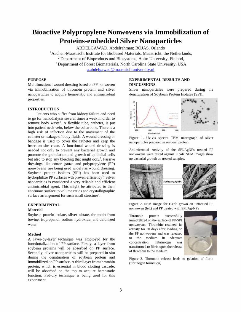
EXPERIMENTAL RESULTS AND
DISCUSSIONS
Silver nanoparticles were prepared during the
denaturation of Soybean Protein Isolates (SPI).
Figure 1. Uv-vis spectra TEM micrograph of silver
nanoparticles prepared in soybean protein
Antimicrobial Activity of the SPI/AgNPs treated PP
nonwovens were tested against E.coli. SEM images show
no bacterial growth on treated samples.
Figure 2. SEM image for E.coli grown on untreated PP
nonwoven (left) and PP treated with SPI/Ag-NPs
Thrombin protein successfully
immobilized on the surface of PP/SPI
nonwovens. Thrombin retained its
activity for 30 days after loading on
the PP nonwovens and was released
to the medium in adequate
concentration. Fibrinogen was
transformed to fibrin upon the release
of thrombin to the medium.
Figure 3. Thrombin release leads to gelation of fibrin
(fibrinogen formation)
Soybean/AgNPs

4
CONCLUSIONS
Antimicrobial and hemostatic properties were acquired
to the surface of polypropylene nonwovens through the
immobilization of soybean and thrombin proteins.
Silver nanoparticles were prepared in-situ during the
denaturation of soybean protein. The functionalized
nonwovens remained active for 30 days when stored at
room temperature.
SUGGESTION FOR FURTHER WORK
Solvent free (solid state) and large scale synthesis of
silver nanoparticles using soybean isolate. In addition,
in-vitro blood coagulation assessment should be done
on the treated PP nonwovens.
ACKNOWLEDGEMENTS/SOURCES OF
FUNDING
The authors are thankful to the United Soybean Board
of the United States for providing soybean isolates for
the experiments.
LITERATURE
1-Abdelgawad, A. M., et al. (2014). "Antimicrobial
wound dressing nanofiber mats from
multicomponent (chitosan/silver-NPs/polyvinyl
alcohol) systems." Carbohydrate polymers 100: 166-
178.
2-Kamoun, E. A., et al. (2017). "A review on
polymeric hydrogel membranes for wound dressing
applications: PVA-based hydrogel dressings."
Journal of advanced research 8(3): 217-233.
3-Mermel, L. A. (2000). "Prevention of intravascular
catheter–related infections." Annals of internal
medicine 132(5): 391-402.
4-O'grady, N. P., et al. (2011). "Guidelines for the
prevention of intravascular catheter-related
infections." Clinical infectious diseases 52(9): e162-
e193.

5
Biofunctionalization of hydrogels for tissue
engineering applications AVCI-ADALI, Meltem1
1University Hospital Tübingen, Dept. of Thoracic and Cardiovascular Surgery, Tübingen, Germany
PURPOSE
Functionalization of hydrogels for improved tissue
regeneration
INTRODUCTION
Hydrogels are one of the most attractive biomaterials
for tissue engineering, since they can be used to
generate three-dimensional scaffolds to support the cell
growth and to improve the healing of tissues 1.
EXPERIMENTAL
Material
For the generation of hydrogels, gelatin methacryloyl
(GelMA) or circularized single-stranded DNA were
used. VEGF binding aptamers were covalently
incorporated into the hydrogels.
Method
Three-dimensional GelMA and DNA hydrogels were
generated2. These hydrogels were functionalized with
VEGF binding aptamers. The functionalization of the
hydrogels with the aptamer was analyzed by application
of FAM-labelled complementary oligonucleotides. The
successful loading of hydrogels with VEGF was
determined by using ELISA. The bioactivity of the
VEGF in hydrogels was verified by incubation of
HUVECs with hydrogels.
EXPERIMENTAL RESULTS AND
DISCUSSIONS
The successful loading of the hydrogels with VEGF
was demonstrated. Furthermore, improved
angiogenesis was shown after the incubation with
HUVECs. These results demonstrated the promising
application possibilities of aptamers as capturing
molecules in three-dimensional hydrogels.
CONCLUSIONS
The generation of aptamer-functionalized hydrogels
has a huge potential for regenerative medicine.
Aptamers against different targets can be applied to
produce hydrogels with altered functions.
SUGGESTIONS FOR FURTHER WORK
In the future, three-dimensional structures will be
generated using 3D printing technology. Furthermore,
in vivo studies will be performed to verify the
obtained in vitro results.
LITERATURE
1 Guan X, Avci‐Adali M, Alarçin E, Cheng H, Kashaf
SS, Li Y, Chawla A, Jang HL, Khademhosseini A.
Development of hydrogels for regenerative
engineering. Biotechnology journal. 2017,
12(5):1600394.
2 Stoll H, Steinle H, Stang K, Kunnakattu S,
Scheideler L, Neumann B, Kurz J, Degenkolbe I,
Perle N, Schlensak C, Wendel HP, Avci-Adali M.
Generation of Large‐Scale DNA Hydrogels with
Excellent Blood and Cell Compatibility.
Macromolecular bioscience. 2017, 17(4):1600252.

6
Biodegradable Polymers for Tissue Engineering ARMAN, Nazlı 1, ULCAY, Yusuf1
Bursa Uludag University, Faculty of Engineering, Department of Textile Engineering [email protected]
PURPOSE
Scaffolds are vital for tissue engineering researching.
Through manufacturing technologies and studies to
improve the properties of polymers biocompatible,
scaffolds are made by more compatible with the body.
In this article, considering the chemical structure of
biodegradable polymers with their relationship with
mechanical, biocompatibility, electrical conductivity
properties will be examined.
INTRODUCTION
Accidents or various diseases result in tissue or organ
losses that significantly affect human’s lives. At this
point, tissue engineering; provides interdisciplinary
studies of health sciences and various engineering to
improve or repair existing tissue functions. In
therapeutic applications, the mimetic tissue may
develop in the patient's body (in vivo), may also
develop in the laboratory environment.
2. Polymers Used in Tissue Engineering
The extracellular matrix consists of various proteins
and polysaccharides, providing physical support as well
as providing organization of cells. The surface of the
tissue scaffold to be produced must be considered for
the specific chemical and morphological structure
(extracellular matrix) for each cell to hold and
proliferation. This review article will be discussed
commonly used polymers in scaffold applications.
Aliphatic Polyester
Polylactic acid (PLA), polyglycolic acid (PGA), and
copolymers of these polymers are poly (lactide-co-
glycolide) (PLGA). They are degraded by hydrolysis of
ester groups in their main chains. PGA is highly
crystalline and rapidly soluble in water. The
disadvantage is that it loses its mechanical strength
considerably within 2-4 weeks of implantation.
Degredation rate; molecular weight, the design of the
tissue scaffold and the structure of the environment in
which it is placed. PLA, the second most widely used
biodegradable polymer, is more hydrophobic than PGA
due to the extra methyl group in the structure, and thus
loses its mechanical strength significantly, although it
takes several years to degrade in the body completely.
Poly (ε-caprolactone) (PCL) is a semi-crystalline
material and has a rubbery behavior throughout the
body since its glass transition temperature is about -60
° C [3].
Polyurethanes
Due to the easy modification of the chemical structure
of the polyurethane, which consists of two different
segments (diisocyanate and polyol), materials with
very different physical and biocompatibility
properties, can be produced. The products formed as
a result of degradation do not show toxic effects. In
recent studies, it has been observed that by using
amino acid-derived diisocyanate, more cells are
attached and produced on the surface of the material
than polyurethane produced by toluene diisocyanate.
Today, artificial capillaries, cartilage and hard bone
tissue, nerve tissue, and is used in areas such as drug
transport [1,4].
Poly (glycerol sebacic acid)
The Langer research group synthesized it in 2002,
during the search for new materials with better
mechanical and chemical properties for soft tissue
production. It is synthesized by condensation of
glycerol and sebacic acid. It shows cross-linked
elastomer behavior due to the hydrogen bond formed
between hydroxyl groups. In order to adjust the rate
of degradation by considering the characteristics of
the target tissue to be imitated, curing time and
temperature, monomer concentration, the ratio of
acrylate group in the structure by changing the
different properties of polyglycerol sebacic acid
derivatives can be produced. It has various
applications such as hard bone tissue, drug delivery
[3].
CONCLUSİON
The studies in the field of tissue engineering are
increasing day by day. It is predicted that the success
rate will increase with the developments in the
materials and production technologies whose
properties are developed. Following the production of
tissues such as vascular and nerve tissues, which are
very difficult to imitate, the next stage is the
production of artificial organs.
RESOURCES
1-Bergmeister H., 2014. “Biodegradable,
thermoplastic polyurethane grafts for small diameter
vascular replacements”, Acta Biomaterialia, 2.
2-Christiaan L. E. Nijst, 2007. “Synthesis and
Characterization of Photocurable Elastomers

7
from Poly(glycerol-co-sebacate)”, Biomacromolecules,
3067-3073.
3-GUO BaoLin, 2014. “Synthetic biodegradable
functional polymers for tissue engineering:
a brief review”, Science China Chemistry, 2.
4-Skarjia G. A., 2001. “In vitro degradation and erosion
of degradable, segmented polyurethanes containing an
amino acid-based chain extender”, J. Biomater. Sci.
Polymer Edn, Vol. 12, No. 8, pp. 851–873.

8
DESIGN AND DEVELOPMENT OF A PERSONALIZED
MEDICINE ORIENTED MICROFLUIDIC ORGAN ON A
CHIP PLATFORM
KIZILKURTLU, Ahmet Akif1, AKPEK, Ali1 1Gebze Technical University
PURPOSE The main purpose of the experiment was fabricating a
novel skin-on-a-chip system via using PMMA plate
that was consisting of ten layers with eight bolt and
loafs insertion holes. Furthermore, two different
GelMA-Sodium Alginate solution was prepared to be
used as bio-ink for skin scaffold.
INTRODUCTION
Bringing a drug in health sector costs about 2 billion
dollars and the process takes from 12 to 15 years. One
of the most important step of these studies is
preclinical testing, the other names is animal testing,
which is also so crucial in cosmetic toxicity testing and
disease modelling. Preclinical testing consists of two
different implementations as in vitro analyses by using
proper cell line models and in vivo studies via using
animal models. All of these processes are conducted to
determine not only validity and toxicity, but also
pharmacokinetic and pharmacological characteristics
testing to analyze the absorption, distribution,
metabolism and excretion rate of the substance, which
is crucial for detecting the he basic safety and potential
usefulness of the drug (candidate). Eventually, the
compounds that are passed the previous procedures are
subjected to clinical trials (human trials) in order to
specify the ultimate validity, effectivity, and
usefulness of the drug. Although the investigation and
researches on new drug candidates for acute, chronic
and genetic diseases are being performed accelerando,
the rate of finding successful and effective drug
reagents is dramatically low [3, 5, 6]. That is because
either lack of clinical efficacy or intolerable toxicity of
the drug candidates during investigation process [2, 4].
Since the mentioned processes are expensive and time
consuming [1], it is very important to detect the
compounds that are potentially ineffective or have an
unacceptable toxicity and dismiss in early stages of
drug development. Therefore, development of in vitro
cell-based testing methods are crucial and necessary to
provide possibility to predict precisely for efficacy and
safety of drug candidates. Cell cultures for both drug
development and disease modelling can be categorized
as 2D cell culture, 3D cell culture (involves 3D bio-
printing technology), and microfluidic systems.
Microfluidic systems that are most advanced discovery
and the whole of the applications of engineering
disciplines such as bioengineering, chemical
engineering, and material engineering. These systems
have demonstrated that they can be suitable candidates
and platforms for drug development, cosmetic toxicity
testing, and disease modelling implementation instead
of animal models by the studies of organ-on-a-chip
systems.

9
EXPERIMENTAL Material The materials that were used in this study can be
specified as: PMMA plate, 8 bolts, 8 loafs, injection
pipe (silicon), Mouse fibroblast cells, micropipettes,
confocal microscopy, glass-plastic petri dishes (120 x
15, 90 x 15), injectors (50 ml, 20 ml), syringe pump
Method Fabrication of skin chip via using PMMA plate by
utilizng laset etching machine. Production of skin
scaffold by using GelMA- Sodium Alginate solution
as bioink. Mouste fibroblast cell culture on skin
scaffold that placed on skin chip. Utilizng Confocal
microscopy for analyzing cell viability.
EXPERIMENTAL RESULTS AND
DISCUSSION
The results of the experiments has shown that the skin
chip system has demonstrated that it was more
successful compared to petri dihes. The general
composition of the scaffold was more stable in the
chip, because the scaffold in petri dishes were torn
apart in second day. Furhermore, detected amount of
fibroblast cells were higher in the chip system.
Besides, dead-alive cell ratio was better in the chip
system. The chip system has proven that it was better
and more effective against petri dish. Therefore it can
be used as disease modelling, durg validity, effectivity,
and cosmetic toxicicty testing. Figure 1 shows an
example of cells in chip and Figure 2 shows an
example of cells in petri. Figure 3 shows the detected
amount of cells in the systems and Figure 4 shows the
detected amount of dead-alive cell ratio.
Figure 1, and image of second day image of
cells in the microfluidic system
Figure 2, an image of second day image of
cells in the petri,
Figure 3, detected amount of the cells in the
chip and in the petri
3655
106
19 17 15
0
50
100
150
1 . D A Y 3 . D A Y 7 . D A Y
DTE
CTE
D A
MO
UN
T O
F C
ELL
1 0 % - 7 % G E L M A - S O D I U M A L G I N A T E C O N T A I N I N G S C A F F O L D
Chip Petri

10
Figure 4, detected amount of dead-alive cell
in 10%-7% GelMA-Sodium Alginate
containing scaffold
CONCLUSION
In this study, PMMA was utilized as main material of
the skin-on-a-chip. It was fabricated ten-layered
structure. Eight hole in the same size were inserted in
the system during the design in order to provide easy
integration and disintegration for reproducibility. The
bolts were used to integrate the layers of the chip.
Besides, two different scaffolds were printed. The
former one was comparing the chip system with glass
petri with 7%-5% GelMA-Sodium Alginate mixture
and the latter one was comparing the chip system with
plastic petri with 10%-7%. Mouse fibroblast cells were
used for cell culturing.
SUGGESTION FOR FURTHER WORK The further and more detailed optimizations such as
optimizing the cell chamber dimeter, width of the inlet
and outlet channels, tighter integration of the layers
and the flow rate of the medium from injection pump
are the following objectives of this study. If the
mentioned enhancements can be executed, the chip
will have shown a great promise to use as a platform
for drug delivery, toxicity, and effectivity testing
instead of animal models , cosmetics toxicity testing,
disease modelling and most importantly personal-
oriented disease modelling.
LITERATURE 1. DiMasi, J.A., R.W. Hansen, and H.G.
Grabowski, The price of innovation: new
estimates of drug development costs. Journal
of health economics, 2003. 22(2): p. 151-185.
2. Hopkins, A.L., Network pharmacology: the
next paradigm in drug discovery. Nature
chemical biology, 2008. 4(11): p. 682.
3. Hutchinson, L. and R. Kirk, High drug
attrition rates—where are we going wrong?
2011, Nature Publishing Group.
4. Kola, I., The state of innovation in drug
development. Clinical Pharmacology &
Therapeutics, 2008. 83(2): p. 227-230.
5. Kola, I. and J. Landis, Can the
pharmaceutical industry reduce attrition
rates? Nature reviews Drug discovery, 2004.
3(8): p. 711.
6. Pangalos, M.N., L.E. Schechter, and O.
Hurko, Drug development for CNS disorders:
strategies for balancing risk and reducing
attrition. Nature Reviews Drug Discovery,
2007. 6(7): p. 521.
0
20
40
60
80
100
120
Chip -1. Day
Chip -3. Day
Chip -7. Day
Petri -1. Day
Petri -3. Day
Petri -7. Day
36
55
106
19 17 151
14
51
6 11 15
DET
ECTE
D A
MO
UN
T O
F C
ELLS
10%-7% GelMA-SODIUM ALGINATE CONTAINING SCAFFOLD
Alive Dead

11
Enhancement of Mechanical Properties of Poly(lactic acid)
by Blending with Epoxidized Natural Rubber GUMUS, Omer Yunus1, OZBAY, Ceren2
1Bursa Technical University, Department of Fiber and Polymer Engineering, Bursa, Turkey. 2Brisa Bridgestone Sabanci Tyre Manufacturing and Trading Inc., Material Development
Department, Kocaeli, Turkey.
PURPOSE
In this study, imporovement in mechanical properties of
poly(lactic acid) (PLA) is aimed by blending with
natural rubber (NR). NR was epoxidized in order to
ensure compatibility with PLA. Mechanical properties
and optical microscope images of PLA blends with NR
and epoxidized natural rubber (ENR) were
comperativly investigated.
INTRODUCTION
Demand on polymeric materials have been increasing
for decades due to their supreme properties over other
class of materials such as lightness, corrosion
resistance, easy processing, elasticity etc. The annual
global production of polymers elevated from about 100
million tonnes in 1990 to 200 million tonnes and
reached 350 million tonnes in 2017 (Nova Institute
report). As a consequence of the unconscious
consumption, polymeric wastes have become one of the
main environmental problem for the planet. In recent
years some measures and solutions have been seeking
to overcome this issue. Usage of biodegradable
polymers has been evaluated as one of the promising
solution for the pollutions.
Beside the negative effect on the environment,
petroleum based polymers have also some economical
risks. Finite reservoir of crude oil and its fluctuating
prices imposed by political inconsistencies may be
shown as major reasons for the economic concerns. Bio
based polymers can be considered as substantial
alternative in terms of resource diversity. Hence
decreasing of dependence on petroleum in polymer
industry may sustain stability of the prices.
PLA is one promising polymer as it is both bio based
and biodegradable. However, it is usage in many
application is limited because of high brittleness. Many
efforts have been done to remove this drawback of
PLA. Preparation of blends and composites is the main
strategy to enhance mechanical properties of PLA
(Hedayati et al.) (Eselini et al.). However, in order to
conserve bio material classification, all the materials
used in blend or composite besides PLA should be also
bio-based. In this sense, natural rubber (NR) with its
high toughness is a good candidate for PLA blends. At
that point, the weak compatibility of NR with PLA
appears as a problem to achieve a homogenous
structure in the blend.
To improve the miscibility between PLA and NR
many study have been carried out in the literature.
Cao et al. (Cao et al.) used cellulose nanocrystals as a
compatibilizer for PLA/NR blends. In another work,
Huang and coworkers prepared NR-PMMA
copolymers to achieve homogeneity in PLA/ NR-
PMMA/NR ternary blend (Huang et al.). Maleic
anhydride (Klinkajorn and Tanrattanakul),
multiwalled carbon nanotube (Desa et al.), PMMA-
grafted-cellulose (Rosli et al.) were also used as a
compatibilizer.
In this study, epoxidized natural rubber (ENR) was
used as a toughening material for PLA. Firstly, ENR
was obtained from NR. Then PLA/ENR blends were
prepared. Morphological and mechanical properties
of PLA/NR and PLA/ENR blends were investigated
and the results were comparatively evaluated.
EXPERIMENTAL
Material
In this study NR (SVR3L grade) and PLA
(NatureWorks Ingeo 4043D Natural) were used. H2O2
(50%) and glacial acetic acid were purchased from
Sigma-Aldrich. Toluen, chloroform, acetone and
methanol were purchased from Merck.
Method
ENR was obtained from reaction of NR with peracetic
acid at room temperature.
Solution casting method was used to prepare the blend
films.
Morphologies of the blend films were investigated by
optical microscope. Mechanical tests were carried out
by using SHİMADZU - AGS-X universal test
instruments.
EXPERIMENTAL RESULTS AND
DISCUSSIONS
In order to investigate miscibility of PLA with NR and
ENR, optical microscope images of the blend films
were recorded. As seen from Figure 1a, a phase
separation occurred in %50PLA/NR blend film. This
result clearly shows that there is not adequate

12
compatibility between PLA and NR which results in a
heterogeneous structure formation. A phase separation
is not desired to achieve good mechanical properties. In
contrast, formation of an entirely homogeneous
structure was observed for %50PLA/ENR blend films.
This result is attributed to the introduction of polar
epoxy rings to the NR structure which enables a
demanded interaction with ester moieties in the PLA
structure.
Figure 1. Optical microscope images of
(a)%50PLA/NR, (b) %50PLA/ENR blend films
Stress and strain curves of the samples were given in
Figure 2. It is clearly seen that stress and strain values
of PLA/ENR blend at break is four and three times
higher, respectively, than those of PLA/NR blend
owing to the better miscibility and homogeneous
structure.
Figure 2. Stress and strain curves of %50PLA/NR and
%50PLA/ENR blend films
CONCLUSIONS
PLA has better miscibility with ENR than NR, since
interaction between polar moieties. Therefore, a
homogeneous structure was achieved with PLA/ENR
blend. PLA/ENR blend film exhibits better mechanical
propertied than PLA/NR blend due to its homogenous
structure.
SUGGESTION FOR FURTHER WORK
Blend films can be prepared with various PLA content.
Thermal properties and crystallinities of the blends may
also be investigated in order to further discuss
mechanical properties.
ACKNOWLEDGEMENTS/SOURCES OF
FUNDING
We are grateful to Scientific Research Projects Units
of Bursa Technical University for the financial
support (Project No: 172L21)
LITERATURE
Cao, L. M., C. Liu, D. J. Zou, S. D. Zhang, and Y. K.
Chen. 2020. 'Using cellulose nanocrystals as
sustainable additive to enhance mechanical and shape
memory properties of PLA/ENR thermoplastic
vulcanizates', Carbohydrate Polymers, 230: 8.
Desa, Mszm, A. Hassan, A. Arsad, and R. Arjmandi.
2019. 'Effect of core-shell rubber toughening on
mechanical, thermal, and morphological properties of
poly(lactic acid)/multiwalled carbon nanotubes
nanocomposites', Journal of Applied Polymer
Science, 136: 7.
Eselini, N., S. Tirkes, A. O. Akar, and U. Tayfun.
'Production and characterization of poly (lactic acid)-
based biocomposites filled with basalt fiber and flax
fiber hybrid', Journal of Elastomers and Plastics: 16.
Hedayati, F., N. Moshiri-Gomchi, M. Assaran-
Ghomi, S. Sabahi, N. Bahri-Laleh, S. Mehdipour-
Ataei, J. Mokhtari-Aliabad, and S. A.
Mirmohammadi. 'Preparation and properties of
enhanced nanocomposites based on PLA/PC blends
reinforced with silica nanoparticles', Polymers for
Advanced Technologies: 8.
Huang, J. M., W. J. Mou, W. T. Wang, F. Lv, and Y.
K. Chen. 'Influence of DCP content on the toughness
and morphology of fully biobased ternary PLA/NR-
PMMA/NR TPVs with co-continuous phase
structure', Polymer-Plastics Technology and
Materials: 11.
Klinkajorn, J., and V. Tanrattanakul. 2020.
'Compatibilization of poly(lactic acid)/epoxidized
natural rubber blend with maleic anhydride', Journal
of Applied Polymer Science, 137: 9.
Rosli, N. A., I. Ahmad, F. H. Anuar, and I. Abdullah.
2019. 'Application of polymethylmethacrylate-
grafted cellulose as reinforcement for compatibilised
polylactic acid/natural rubber blends', Carbohydrate
Polymers, 213: 50-58.
13
Tıbbi Plaster Kumaşı Üretimi İçin İplik Haşıl Kriterlerinin
Araştırılması ve Performans Testleri KOPTAGEL, Hüner1, GÜRLER, Hale1, TURGUT, Halil İbrahim1
1Harput Tekstil San. ve Tic. A.Ş., Ar-Ge Merkezi
AMAÇLAR
Çalışmada Türkiye’de üretimi yapılmayan ve ülkemize
ithal olarak giren, yara üzerine yapıştırılarak
mikroplardan koruyan tıbbi ipek görünümlü plaster
kumaşının üretilebilmesi için ipek görünümlü selüloz
asetat (CA) ipliğinin haşıllanma süreçleri çalışılmıştır.
GİRİŞ
Tekstilin tıp alanında kullanımı tıbbi tekstiller olarak
bilinen yeni bir şubeye yol açmıştır1. Tıbbi tekstil
malzemeleri, farklı elyaf ve tekstil yapılarına sahip çok
çeşitli elyaf bazlı ürünleri içerir. Tıbbi tekstiller, tıbbi
bir ortamda ya bir yaralanmanın tedavisi için ya da bir
yaranın ya da bir hastalığın klinik tedavisinde uygun bir
koşulun sağlanması için kullanılmaktadır2.
Uygulamalara bağlı olarak, tıbbi tekstiller için ana
gereklilikler emicilik, dayanıklılık, esneklik,
yumuşaklık, biyouyumluluk ve zaman zaman biyolojik
kararlılık veya biyobozunurluktur. Bu gereksinimler,
çeşitli son kullanıcıların ihtiyaçlarını karşılamak için
doğru yapılara sahip liflere ve tekstillere işlenmiş
uygun polimerler kullanılarak karşılanır. Biyouyumlu,
biyobozunur ve toksik olmayan doğal polimerlerin
kullanımına yönelik genel bir hareket vardır 2.
Selüloz asetat (CA) lifleri yenilenebilirlik, non-toksik
ve bozunabilirlik gibi avantajlara sahiptir. Ek olarak,
CA elyafları mükemmel nem adsorpsiyonu ve nem
serbest bırakma özelliklerine sahiptir. Bu nedenle, CA
elyafları kullanım rahatlıkları ve ipek benzeri hisleriyle
tanınmaktadır3. Selüloz asetatın çeşitli uygulamaları
arasında tıbbi gazlı bez, kurdela, tabut astarı, ev
eşyaları, dokuma kadife, dokuma satenler ve diğerleri
sayılabilir. Ek olarak, ürün iyi tokluk, derin parlaklık ve
yüksek şeffaflık sunar. Nem tutma ve bakteriyel türlere
(Staphylococcus aureus, Escherichia Coli ve Candida
albicans mayası) karşı antibakteriyel özellikleri
nedeniyle yara pansumanlarında, kişisel hijyen
ürünlerinde ve emici çamaşır ve mendillerde kullanılır.
Uygulama segmentinde sigara filtreleri, fotoğraf
filmleri, bantlar ve etiketler, gözlük çerçeveleri de yer
almaktadır4.
Bu çalışmada,biyobozunur özelliğe sahip çevre dostu,
yenilenebilir ve sağlık açısından herhangi bir tehdit
oluşturmayan selüloz asetat liflerine sentetik haşıl
maddesinin aplikasyonu çalışılmıştır.
DENEYSEL
Malzeme
Çalışmada 50 denye ham parlak selüloz asetat lifleri
ile çalışılmıştır. Dokuma yapısı oluşturabilmek için
çözgü ipliklerine fiziksel ve yapısal olarak
mukavemet kazandırılması için polyester reçine esaslı
haşıl maddesi kullanılmıştır. Ayrıca SSM bobin
aktarma makinesi kullanılmıştır.
Yöntem
Çalışmada 2 yöntem ile çalışılmıştır. Bunlar tek tel
soğuk haşıl ve soğuk haşıldan sonra ısıtıcı yardımıyla
kurutulması şeklindedir. Her iki yöntemde de farklı
hız denemeleri yapılmıştır.
İplik numarası ISO 2060, iplik kopma mukavemeti ve
uzama değerleri ISO 2062 standartlarına göre
belirlenmiştir.
DENEYSEL SONUÇLAR/TARTIŞMA
Çalışma kapsamında asetat ipliğine işletme
şartlarında haşıl teknesinde işlem yapılması
öngörülmüştür. Haşıl teknesinde iş akışında temel
adımlar çözgü hazırlama, haşıllama işlemi, haşıllı
ipliğin kurutulması, haşıllanan ipliğin dokuma
levendine sarımı şeklindedir. Ancak hem ipliğin 50
denye ve filamenti yapıda olması hemde otomasyon
tabanlı tansiyonel sebeplerle çözgü hazırlıktan haşıl
prosesine geçiş prosesinde başarılı olunamamıştır.
Bu sebeple selüloz asetat ipliğini tek tel halinde
haşıllamak üzere arge çalışmaları başlatılmıştır.
Öncelikle çalışmalar haşıl dairesinden iplik aktarma
dairesine taşınmıştır. Bobin aktarma ünitelerinde,
ipliğin sakal yapmasını,elektriklenmesini ve
kopmasını engellemek amacıyla, içinin endüstriyel
yağ ile dolu olduğu bir hazne mevcuttur.
Bu hazne içerisine polyester reçine esaslı haşıl
maddesi konularak haşıl kimyasalının ipliğe aplike
edilmesi sağlanmıştır.

14
Tablo 1. Polyester reçine uygulanmış selüloz asetat
ipliği test sonuçları
Tablo 2. İnfrared kurutma sistemli polyester reçine
uygulanmış selüloz asetat ipliği test sonuçları
Tablo 1 ve 2 de yapısına aynı haşıl malzemesi aplike
edilmiş selüloz asetat ipliklerinin test sonuçları
verilmiştir. Bobin sarım hızı ve yağ rulo hızlarında
değişkilikler yapılarak yapıya alınan haşıl madde
miktarının iplik mukavemetine etkisi gözlemlenmiştir.
Tablolar incelendiğinde 250/4 ve 450/4 denemelerinde
mukavemet değerlerinin daha fazla iyileştiği
görülmektedir. İnfrared kurutuculu sistemin ise iplik
mukavemetine olumsuz yönde etki ettiği görülmüştür.
GENEL SONUÇLAR
Kateter, sargı bezi ve yara örtüsü gibi tıbbi malzemeleri
cilt üzerine sabitlemek için üretilmesi amaçlanan
selüloz asetat esaslı plasterin ilk ve en önemli adımı
olan haşıl süreci verimli geçmiştir.
Bobin aktarma makinasında yapılan küçük
değişikliklerin iplik mukavemeti ve uzama değerlerinde
önemli ölçüde değişiklikler meydana getirdiği
görülmüştür.
KAYNAKLAR
1 Vaishya, R. Agarwal, A. K. Tiwari, M. Vaish, A.
Vijay, V. Nigam, Y. 2018. “Medical textiles in
orthopedics: An overview”, Journal of Clinical
Orthopaedics and Trauma, 9, 26-33.
2 Qin, Y. 2016. Medical Textile Materials. Woodhead Publishing.
3 Yuan W. Wu K. Liu N. Zhang Y. Wang H. 2018.
“Cellulose acetate fibers with improved mechanical
strength prepared with aqueous NMMO as solvent”,
Cellulose, 25, 6395–6404.
4 “Cellulose Acetate Market 2019: by Type, by Type,
by Application, by Region- Global Market Size,
Share, Development, Growth, and Demand Forecast-
2023”. https://www.marketwatch.com/press-
release/cellulose-acetate-market-2019-by-type-by-
type-by-application-by-region--global-market-size-
share-development-growth-and-demand-forecast---
2023-2019-03-27,
SONRAKİ DÖNEM ÇALIŞMALARI
Verimli geçen ipik haşıllama sürecinden sonra
kontrüksüyonu tasarlanan plaster kumaşı dokuma
prosesi gerçekleştirilmesi ve performans testlerinin
bünyede bulunan test ekipmanları ile yapılması
amaçlanmaktadır.
TEŞEKKÜR/BILGILENDİRME/FON
KAYNAĞI
Çalışmada emeği geçen iplik büküm departmanına,
iplik performans testlerinin yapılmasında destek
veren Harput Tekstil çatısı altındaki Miranlı İplik
firmamıza ve finansman sağlayıcısı olan Harput
Tekstil San. Ve Tic A.Ş. ye teşekkürü borç biliriz.
Analizi yapılan numune
(bobin dönüş hızı/yağ rulo
dönüş hızı) (dev/dk)
Dtex Uzama (% )Mukavemet
(cN/dtex)
Ham İplik 57,5 16,32 1,14
250/4 62 16,97 1,34
250/6 64,5 17,14 1,30
450/4 59,5 17,89 1,41
450/6 63 17,10 1,32
Analizi yapılan numune
(bobin dönüş hızı/yağ rulo
dönüş hızı) (dev/dk)
Dtex Uzama (% )Mukavemet
(cN/dtex)
Ham İplik 57,5 16,32 1,14
250/4 infrared kurutmalı 64 18,10 1,32
250/6 infrared kurutmalı 63,5 14,58 1,24
450/4 infrared kurutmalı 62,5 16,78 1,26
450/6 infrared kurutmalı 64 18,22 1,32
15
Characterization Study of Drug Loaded PLA Electrospun
Nanofibers
BARBAK, Zarife1, KARAKAŞ Hale1, SARAÇ, A.SEZAİ2
1Istanbul Technical University, Faculty of Textile Technologies and Design, ISTANBUL
2Istanbul Technical University, Faculty of Science and Letters, ISTANBUL
PURPOSE OF THE STUDY
This study was aimed to fabrication and
characterization of silversulfadiazine (SSD) loaded
poly(lactic acid) (PLA)/Polyetyleneoxide (PEO)
composite nanofiber patches for drug delivery
systems. The SSD loaded nanofibers were
investigated by SEM and XRD.
INTRODUCTION
Nanofibers have unique properties such as high
porosity, high surface area, imitating the Extra
Cellular Matrix (ECM), formation of suitable
conditions for cell proliferation and enabling drug
delivery. Because of these desirable characteristics,
nanofibers are widely used in biomedical
applications such as wound dressings, drug delivery
systems, scaffolds and artificial blood vessels [1].
Drug-delivery systems consist of a formulation or a
device that facilitates introduction of a drug in the
body and enhances the treatment efficiency, supplies
sufficient drug content in the blood during the
release action and carries drug to target point safely
and reduces side effects of release within the body
[2].
Silver sulfadiazine (SSD) is a non-ionised, water
insoluble complex silver salt. SSD is used
extensively in topical treatment of infected burns.
However, the solubility problem of SSD lacks
treatment efficiency. Thence, some authors focused
on to increase the solubility of SSD with using
different dosage forms [3].
Hydrophilic / hydrophobic polymer blends have
been electrospun into nanofibers to control of drug
delivery. The hydrophobic polymer degrades slowly
that makes release at a steady state whereas the
hydrophilic polymer degrades rapidly that
accelerates the drug release [4]. In this context,
hydrophilic PEO and hydrophobic PLA were
blended and utilized for controlled drug release.
PEO is a widely used polymer in drug delivery
because of water solubility, low toxicity,
biocompatibility and biodegradability. PEO interacts
with the body fluid due to hydrophilicity quickly that
results in degradation. PEO was utilized in the
polymer matrix to enhance solubility and
bioavailability of SSD due to its high water
solubility. Furthermore, PEO provides
homogenuous drug distribution [5]. While PEO is a
hydrophilic polymer, PLA is a hydrophobic
aliphatic polyester and has a renewable source,
making it favorable for biomedical applications.
Hydrophobicity of PLA provides long term
degradation rate thus sustained and controlled drug
release could be achieved [6].
In this study, firstly process and solution parameters
were optimized for the nanofiber production, SSD
was used as a drug and added into the PEO solution.
SSD was loaded into PEO. Then PEO+SSD and

16
PLA solutions were blended thus composite
electrospun nanofibers were fabricated.
XRD analysis was performed with SSD loaded and
pure nanofibers. Also surface morphology of
nanofibers were carried out by SEM.
EXPERIMENTAL
Materials
Poly (lactic acid) (PLA), Polyetileneoxide (PEO)
Silversulfadiazine were purchased from Sigma
Aldrich.
3,5% PEO solution was prepared in
Acetonitrile/acetic acid. SSD was loaded into 3.5%
PEO solution at a concentration of 12%, respect to
the PEO polymer. 6% PLA solution was prepared in
Acetonitrile/Chloroform. Finally, to obtain a
homogenous blend solution, PLA and SSD loaded
PEO solutions were mixed 7:3 (w/w).
Method
Electrospinning method was used to produce
nanofibers. Electrospun nanofibers were fabricated
with 14 kV high voltage and 1 mL/h feeding rate.
The grounded electrode plate was utilized as a
collector with a fixed distance from the tip to the
collector (12–14 cm).
EXPERIMENTAL RESULTS AND
DISCUSSION
SEM images show that (Figure 1), SSD loaded
smooth and bead free nanofibers were obtained. PEO
fiber diameter decreases from 330 to 290 nm with
the addition of SSD. This is related to the conductive
nature of SSD. When SSD was added into the
polymer solution, the electrical conductivity of the
polymer jet increases that resulting in smaller fiber
diameters. Otherwise, there are bead defects in
native PLA however smooth, uniform, bead free
fibers were obtained in PLA/PEO+SSD composite
nanofiber morphology (Figure 2). This indicates that
blend of PLA, PEO and SSD molecules have good
interaction in the fiber structure. Moreover, SSD was
dissolved and distributed in PLA/PEO matrix
perfectly.
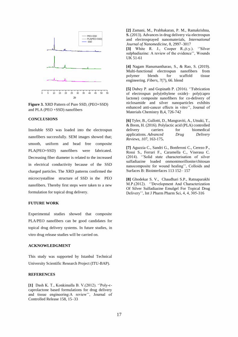
XRD analysis was carried out to determine the
crystallinity of the SSD loaded into the nanofibers.
XRD pattern of silver sulfadiazine loaded PEO
nanofibers and pure PEO nanofibers shown in Figure
3. The diffraction pattern of SSD loaded nanofibers
showed the microcrystalline nature of SSD, as
indicated by the distinctive peaks at 9.7-10,4° and
19,3°[7,8] .
Figure 1. SEM Images of Pure and SSD loaded
PEO nanofibers
Figure 2. SEM Images of a) Pure PLA b) SSD
loaded PLA/PEO (7:3) Composite Nanofiber
X
Pure PEO PEO+SSD
Pure PLA PLA(PEO+SSD
)
17
0 5 10 15 20 25 30 35 40 45 50 55
2
PEO+SSD
PLA(PEO+SSD)
SSD
Figure 3. XRD Pattern of Pure SSD, (PEO+SSD)
and PLA (PEO +SSD) nanofibers
CONCLUSIONS
Insoluble SSD was loaded into the electrospun
nanofibers successfully. SEM images showed that;
smooth, uniform and bead free composite
PLA(PEO+SSD) nanofibers were fabricated.
Decreasing fiber diameter is related to the increased
in electrical conductivity because of the SSD
charged particles. The XRD patterns confirmed the
microcrystalline structure of SSD in the PEO
nanofibers. Thereby first steps were taken to a new
formulation for topical drug delivery.
FUTURE WORK
Experimental studies showed that composite
PLA/PEO nanofibers can be good candidates for
topical drug delivery systems. In future studies, in
vitro drug release studies will be carried on.
ACKNOWLEDGMENT
This study was supported by Istanbul Technical
University Scientific Research Project (ITU-BAP).
REFERENCES
[1] Dash K. T., Konkimalla B. V.(2012). ‘’Poly-є-
caprolactone based formulations for drug delivery
and tissue engineering:A review’’, Journal of
Controlled Release 158, 15–33
[2] Zamani, M., Prabhakaran, P. M., Ramakrishna,
S. (2013). Advances in drug delivery via electrospun
and electrosprayed nanomaterials, International
Journal of Nanomedicine, 8, 2997–3017
[3] White R. J., Cooper R.,(t.y.). ‘’Silver
sulphadiazine: A review of the evidence’’, Wounds
UK 51-61
[4] Nagam Hanumantharao, S., & Rao, S. (2019).
Multi-functional electrospun nanofibers from
polymer blends for scaffold tissue
engineering. Fibers, 7(7), 66. blend
[5] Dubey P. and Gopinath P. (2016). ‘’Fabrication
of electrospun poly(ethylene oxide)– poly(capro
lactone) composite nanofibers for co-delivery of
niclosamide and silver nanoparticles exhibits
enhanced anti-cancer effects in vitro’’, Journal of
Materials Chemistry B,4, 726-742
[6] Tyler, B., Gullotti, D., Mangraviti, A., Utsuki, T.,
& Brem, H. (2016). Polylactic acid (PLA) controlled
delivery carriers for biomedical
applications. Advanced Drug Delivery
Reviews, 107, 163-175.
[7] Aguzzia C., Sandri G., Bonferoni C., Cerezo P.,
Rossi S., Ferrari F., Caramella C., Viserasa C.
(2014). ‘’Solid state characterisation of silver
sulfadiazine loaded onmontmorillonite/chitosan
nanocomposite for wound healing’’, Colloids and
Surfaces B: Biointerfaces 113 152– 157
[8] Ghodekar S. V., Chaudhari S.P., Ratnaparakhi
M.P.(2012). ‘’Development And Characterization
Of Silver Sulfadiazine Emulgel For Topical Drug
Delivery’’, Int J Pharm Pharm Sci, 4, 4, 305-316

18
Photocatalytic Activities of ALD (Atomic Layer Deposition)
TiO2 and ZnO films on Glass Fabrics Islam, Shafiqul 1, Akyıldız, Halil I1
1Bursa Uludag University, Department of Textile Engineering
PURPOSE
The photocatalytic activities of TiO2 and ZnO thin films
fabricated on glass fabrics by atomic layer deposition
were investigated for possible environemental
applications.
INTRODUCTION
Important environmental elements such as water, air
and soil are contaminated, which is damaging the
ecological balance on earth. Among them water is the
most essential element for life cycle of all living
species. Fresh water sources has been contaminated by
industries and agricultural activities leaving hazardous
waste such as pharmaceuticals waste, pesticide,
herbicides, textile dyes, resins, and phenolic
compounds[1,2]. Various methods have been proposed
to treat waste waters but cheaper and less time
consuming is the prime interest in this matter. Among
the porposed techniques are adsorption on activated
carbon, ultrafiltration via reverse osmosis, coagulation
by chemical agents, ion exchange on synthetic
adsorbent, etc. These methods can remove the pollutant
from the water without changing the toxicity of them.
The photocatalytic method offers a way to eliminate the
organic pollutants out of waste water, ideally using
sunlight as a stimulant and reducing toxicity of the
componuds by reducing or oxidizing them.
Semioconductor metal oxides like TiO2 and ZnO have
the ability to create radical species upon absorption of
the light[3,4]. Performance of a catalytic material
increases with increasing surface area. Therefore many
photocatalysis studies being conducted on nanoparticle
materials requiring removal of the particles from water.
As a solution to the problem thin film materials of
photocatalytic materials can be coated on high surface
area substrates such as textiles.
Thin film materials can be formed via chemical vapor
deposition (CVD) and physical vapor deposition
techniques. Atomic layer deposition (ALD) is a CVD
technique in which highly conformal films can be
created even on high surface area substrates due to self
liiting nature of the reactions. ALD also provides
precise thickness and composition control during film
formation making the technique advantegous over other
thin film methods[5]. In this study, phocatalytic
activities of TiO2 and ZnO films deposited on glass
fiber fabrics via ALD. Especially effect of annealing on
photocatalytic activity as well as structure of the films
was investigated.
EXPERIMENTAL
Material Glass fabric, fused quatrz, silicon wafer and glass
slide was used as substates. Tetrakis (Dimethylamido)
Titanium (TDMAT) and Diethyl Zinc (DEZ) were
used as ALD precursors for TiO2 and ZnO
respectively. Water was used for all thin films as
oxygen source.Methylene blue (MB) was used as the
organic pollutant for photocatalytic activity tests.
Method
A 300W solar simulator (UVA) and a 100W UV were
used to as light sources of photocatalytic test. ALD
thin film deposited glass fabrics were placed into 50
ml of MB (5×10⁻⁵ M) solution placed 10 cm below the
light source. UV-Vis spectrophotometer (Shimadzu
3600) was used to measure the relative concentration
(c/c0) change of MB. Absorption spectra of the
materials were obtained using same
spectrophotometer.
RESULTS AND DISCUSSIONS
Fig 1: Photocatalytic activity of a) TiO2 ALD thin film b) ZnO
ALD thin films under solar simulator.
Photocatalytic activity of approximately 10 nm of
TiO2 and ZnO films before and annealing is given in
Figure 1. As coated TiO2 film shows no
photocatalytic activity attributed to the amorphous
nature of the ALD TiO2 films.After annealing TiO2
films photocatalytic activity first increases then
decreases slightly suggesting the annealing as
annealing temperatures increases either larger crsytals
are forming or phase is changing[6]. As coated ZnO
show highiest photocatalytic activity since films are
crystalline. Upon annealing photocatalytic activity
decreases which is attributed to the growth of the

19
crystal grains therefore reducing the defect sites such as
grain boundaires.[7,8]
CONCLUSIONS
ALD coated fabrics substrates showed promising
photocatalytic activity. Annealing of the films
crsytallize the films in some cases increasing the
photocatalytic activity. However annealing at very high
temperatures can have adverse effect on the
photocatalytic activity. Changes in photocatalytic
activity can be explained by the changes in the optical
properties of the films.
ACKNOWLEDGEMENTS/SOURCES OF
FUNDING
Authors acknowledge and would like to thank for
partial funding from Bursa Uludag University (Bilimsel
Araştırma Projeleri, OUAP-2018/7) and TUBİTAK
(Project Numbers; 118M617 and 218M275).
LITERATURE
1. Chong, M. N., Jin, B., Chow, C. W., & Saint, C.
(2010). Recent developments in photocatalytic
water treatment technology: a review. Water
research, 44(10), 2997-3027.
2. Gupta, V. K., Ali, I., Saleh, T. A., Nayak, A., &
Agarwal, S. (2012). Chemical treatment
technologies for waste-water recycling—an
overview. Rsc Advances, 2(16), 6380-6388.
3. Lee, C. S., Kim, J., Son, J. Y., Choi, W., & Kim,
H. (2009). Photocatalytic functional coatings of
TiO2 thin films on polymer substrate by plasma
enhanced atomic layer deposition. Applied
Catalysis B: Environmental, 91(3-4), 628-633.
4. Di Mauro, A., Fragalà, M. E., Privitera, V., &
Impellizzeri, G. (2017). ZnO for application in
photocatalysis: from thin films to
nanostructures. Materials Science in
Semiconductor Processing, 69, 44-51.
5. Johnson, R. W., Hultqvist, A., & Bent, S. F.
(2014). A brief review of atomic layer deposition:
from fundamentals to applications. Materials
today, 17(5), 236-246.
6. Sugapriya, S., Sriram, R., & Lakshmi, S. (2013).
Effect of annealing on TiO2 nanoparticles. Optik-
International Journal for Light and Electron
Optics, 124(21), 4971-4975.
7. Raoufi, D., & Raoufi, T. (2009). The effect of
heat treatment on the physical properties of sol–
gel derived ZnO thin films. Applied Surface
Science, 255(11), 5812-5817.
8. Umar, A., Kumar, R., Kumar, G., Algarni, H., &
Kim, S. H. (2015). Effect of annealing
temperature on the properties and photocatalytic
efficiencies of ZnO nanoparticles. Journal of
Alloys and Compounds, 648, 46-52.

20
IMMOBILIZATION OF CU-BTC ON THE COTTON
FIBERS FOR SENSOR APPLICATIONS SAYGI, Gizem1, ÇAKICIOĞLU ÖZKAN, Fehime1, GÜNER, Cemal1
1Izmir Institute of Technology, Department of Chemical Engineering, İzmir, Turkey
PURPOSE
The aim of this study is to synthesize Cu-BTC and
immobilize onto the cotton fabric using for sensor
activity. The chemical sensing property of Cu-BTC
deposited cotton aganist NH3 gas was studied.
INTRODUCTION
Metal-organic frameworks (MOFs) which are
prepared in the form of one, two or three-
dimensional networks using inorganic salts and
multidentate organic linkers have recently gained
considerable attention due to their large surface
areas, large internal pore volume and ability to bear
various functionalities. Due to these reasons, MOFs
have a wide range of application areas such as gas
storage, sensor, adsorption/separation, and catalysis.
They could be prepared in some various forms such
as beads, pellets and thus, a low-pressure drop and
high performance could be obtained in the industrial
applications 1,5.
The detection of toxic chemicals is a significant issue
to protect people to prevent the inhalation of toxic
chemicals. If the toxic chemicals were not detected,
then many people could be affected from the toxic
chemicals. MOFs have chemical sensing properties
and they could be used to detect several hazardous
gases such as ammonia, chlorine, cyanogen chloride,
hydrogen sulfide, nitrogen dioxide, nitrogen oxide,
sulfur dioxide, phosphine, arsine, radon 6.
Cu-BTC has ability to interact with chemicals so that
it has chemical sensing property. Cu-BTC is used to
detect the hydride gases which are ammonia, arsine,
and hydrogen sulfide 3. Hazardous gases which are
sulfur dioxide, chlorine, radon, cyclohexane,
tetrahydrothiophene, benzene, toluene,
dichloromethane, and ethylene oxide are also
detected by Cu-BTC 6.
The deposition of Cu-BTC on different substrates
provides an easy way to use for sensor activity in
various fields. The deposition of Cu-BTC on
different substrates could be obtained by
solvothermal and non-solvothermal processes 7.
Before the deposition process, sometimes the surface
of the support material should be charged with
required ions to increase the effectiveness of the
deposition process. For deposition of the Cu-BTC,
carboxymethylation is used to obtain a suitable
charge on the surface of cellulose substrates 2.
Pinto et al.4 deposited Cu-BTC on cotton, a
cellulosic fibrous, substrate and then tested for gas
selectivity and toxic chemicals removal. In order to
investigate the importance of carboxylate groups
onto the surface of anionic cellulose. According to
the results, the attachment of Cu-BTC on the cotton
surface was obtained successfully and the order of
addition of Cu(OAc)2-copper acetate, BTH3 4.
In this study, Cu-BTC was deposited onto the cotton
fabric to investigate the sensing properties. Cotton
fabric consists of cellulose which is an abundant
material in nature. A characterization study was
performed to comprehend whether the deposition of
Cu-BTC was achieved successfully or not. Cu-BTC
deposited cotton fabric was characterized by XRD,
SEM, and ATR-IR analysis to investigate the
crystalline structure, surface morphology and
framework vibration of all samples, respectively.
EXPERIMENTAL
Material
Cotton fabric were purchased from Viking Kağıt ve
Selüloz A.Ş. Copper (II) nitrate trihydrate, trimesic
acid, ethanol, N-dimethylformamide (DMF), sodium
hydroxide and sodium chloroacetate were obtained
from Emsure, Sigma Aldrich and Merck.
Method
In order to deposite Cu-BTC on cotton fabric, firstly,
the cotton fabric was carboxymethylated to obtain
anchoring points. Then, Cu-BTC was immobilized
onto the cotton fabric using layer by layer method.
EXPERIMENTAL RESULTS AND
DISCUSSIONS
The Cu-BTC was deposited onto the cotton fibers
successfully. SEM analysis shows that Cu-BTC
crystals were orderly distributed along the cotton
fabrics (Figure 1). Additionally, the surface of the
cotton fabric was intensely covered with Cu-BTC
crystals.

21
The effect of deposition cycle number for layer by
layer method on the amount of deposited Cu-BTC on
cotton fabrics was investigated and the optimum
cycle number was chosen as 10.
Figure 1. SEM micrographs of the cotton fabric (1)
and Cu-BTC deposited cotton fabric (2).
Cu-BTC deposited cotton fabrics have initially light
blue color. After NH3 exposure, the color of the Cu-
BTC deposited cotton fabrics changed and their
color turned to dark blue (Figure 2). Therefore, they
have NH3 sensing property.
Figure 2. Cu-BTC deposited cotton fabric (1), NH3
exposed Cu-BTC deposited cotton fabric (2).
CONCLUSIONS
Cu-BTC was synthesized and immobilized onto the
cotton fabric. Consequently, the results of the
characterization study revealed that the Cu-BTC was
deposited on the cotton fibers successfully. The
optimum cycle number of layer by layer method was
found as 10. Besides, their sensing properties against
the NH3 gas was investigated. The Cu-BTC
deposited substrates showed sensing activity against
NH3 gas.
REFERENCES
1. Abdelhameed, R. M.; Emam, H. E. ; Rocha,
J. ; Silva, A. M. S. 2017. ''Cu-BTC Metal-
Organic Framework Natural Fabric
Composites for Fuel Purification'', Fuel
Processing Technology, 159, 306-312.
2. Küsgens, P., et al. 2009. "Characterization
of metal-organic frameworks by water
adsorption", Microporous and Mesoporous
Materials 120(3), 325-330.
3. Peterson, G. W. ; Britt, D. K. ; Sun, D. T. ;
Mahle, J. J. ; Browe, M. ; Demasky, T, ;
Smith, S. ; Jenkins, A. ; Rossin, A. 2015.
''Multifunctional Purification and Sensing
of Toxic Hydride Gases by CuBTC Metal-
Organic Framework'', Industrial &
Engineering Chemistry Research, 54, 3626-
3633.
4. Pinto, S. ; Augusto, C. ; Hinestroza, J. P.
2012. ''In Situ Synthesis of a Cu-BTC
Metal–Organic Framework ( MOF 199 )
onto Cellulosic Fibrous Substrates:
Cotton'', Cellulose, 19, 1771-1779.
5. Siegle, S.; Kaskel, S. 2009. ''Crystal
Growth of the Metal-Organic Framework
Cu3(BTC)2 on the Surface of Pulp Fibers'',
Advanced Engineering Materials, 3, 93–95.
6. Woellner, M. ; Hausdorf, S. ; Klein, N. ;
Mueller, P. ; Smith, M. W. ; Kaskel, S.
2018. ''Adsorption and Detecdion of
Hazardous Trace Gases by Metal-Organic
Frameworks'', Advanced Materials, 30,
1346-1370.
7. Zhuang, J.; Kind, M. ; Grytz, C. M. ; Farr,
F. ; Diefenbach, M. ; Tussupbayev, S. ;
Holthausen, M. C. ; Terfort, A. 2105.
''Insight into the Oriented Growth of
Surface-Attached Metal−Organic
Frameworks: Surface Functionality,
Deposition Temperature, and First Layer
Order'', Journal of the American Chemical
Society, 137, 8237-8243.
22
One-step preparation and characterization of a
nanostructured hybrid electrode material through a
microwave energy-based approach POYRAZ, Selçuk1
1Department of Textile Engineering, Faculty of Engineering, Adıyaman University, 02040 Adıyaman/TURKEY
PURPOSE
To prepare a hybrid electrode material (HEM)
composed of carbonized conducting polymer (CP), e.g.
polypyrrole (PPy), nanofibers (CNFs) decorated with
nanostructured zinc oxide (nano-ZnO) and carbon
nanotubes (CNTs) through a one-step, hassle-free, rapid
and highly efficient microwave (MW) energy-based
approach.
INTRODUCTION
The growing global demand for clean and renewable
energy,1 the gradual exhaustion of natural fossil fuel
sources,2 and common concerns about the air pollution
and global warming issues3 have stimulated the
academic and industrial societies to spend intense
research efforts on both the development/improvement
of efficient energy storage devices and on sophisticated
energy conversion systems from available natural
sources.4 In this context, the electrochemical energy
storage systems, i.e. supercapacitors (SCs),2,3,5-9 have
attracted a great deal of attention, and in recent years,
they have gained a great technological significance10
upon emerging as an ideal frontline technology11 to
answer these needs and concerns. An ideal hybrid
SC13,14 is mainly composed of both the electric double-
layer carbon (EDLC)-based electrode materials with
high surface area, conductivity and chemical
stability,2,13 and also the pseudo-capacitor (PC) ones
with much higher specific capacitance,10-12 but with
much lower stability and conductivity.8,12-14 The logic
behind the nanostructured synthesis of all these
materials lies beneath the great enhancement
opportunity of their final performance in SCs as the
active electrode materials. For instance, PPy and ZnO-
based electrodes have been observed to exhibit many-
fold increases in their capacitive properties if they
possess nanostructured morphologies. However, most
of the synthetic approaches to obtain these materials in
nano-size, have the potential drawbacks of being; (i)
wet-chemistry dependent (involving volatile organic
solvents, harsh acids/bases, hazardous reducing agents
and potential impurity carry-overs), (ii) time
consuming, and (iii) having multiple steps with high
temperature and pressure requirements.12,20,21 As an
attempt to tackle such drawbacks in synthetic
approaches and to lower the electrode material
fabrication costs,13 in recent years, people have come
up with the idea of using MW energy,10,19 which have
emerged as an affordable, facile, versatile and
promising one-step alternative, based on heating the
MW energy absorbing polar reactants up to elevated
temperatures within very short time frames. In order
to fully benefit from all different components in one
hybrid nano-architecture,22 in this study, a HEM with
accrued advantages,11 i.e. the EDLC property of
CNTs and PC properties of both nano-ZnO and PPy
NFs, was prepared through a well-established and
universal one-step MW energy-based approach called
Pop tube.23 It was reasonably envisaged18 and
speculated that the as-prepared nanostructured HEM
would exhibit enhanced; (i) energy density (via the
synergistic contribution of its each component’s
electro-active features),1,6,11-13,15 and (ii) power
density values (by providing an efficient solution for
the common electrolyte ion diffusion problem). Last
but not the least, other significant advantages of the
one-step MW energy-based approach can be
summarized as being; (i) sustainable,15,21 (ii)
commercially viable,11 (iii) wet-chemistry free,12 (iv)
affordable, (v) easily tunable/scalable for industrial
level,2,12 and (vi) being able to fabricate intimately
connected HEMs for the next-generation SCs. Thus,
the nanostructured HEM obtained from this approach
is aimed to be the material of preference for relevant
applications.
EXPERIMENTAL
Material
The materials used in this study include; pyrrole
(98%), ammonium peroxydisulfate (APS, 98%,
(NH4)2S2O8), and ferrocene (99%, Fe(C5H5)2) from
Alfa Aesar, zinc acetate dihydrate (ZAD,
Zn(CH3COO)2.2H2O) from EMD Chem. Inc., HCl,
acetone, and potassium hydroxide (KOH) from J. T.
Baker, colloidal graphite paste (isopropanol base)
from Electron Microscopy Sciences. V2O5 sol-gel NF
seeds were prepared based on a previously reported
method24 by using ammonium metavanadate
(NH4VO3, 99.5%) from Acros Organics and Dowex
Marathon (H) ion exchange resin from Sigma Aldrich
in DI water.
Method
In a standard process, firstly, 70 mg of the as-
synthesized HCl-doped PPy NF powder and 70 mg

23
ferrocene were placed in a capped 10 mL plastic cup
and blended in a speed mixer at 3500 rpm for 2 min.
Next, this mixture was flatly laid at the bottom of a glass
vial and then its surface was homogenously powdered
with a 100 mg of fine ZAD in the form of a secondary
white layer. After that, the glass vial was loosely capped
and placed into the MW chamber for a short-time heat
treatment that lasted for 30, 60 or 120 s (Figure 1).
Within 10 s of the heating process the mixture was
started smoking and arcing, respectively, and then it
continuously glowed red hot inside the glass vial for the
rest of the process time.22-26 Eventually, the darkened
glass vial was taken out of the MW and left to cool
down to room temperature. Finally, the dark residue
with a grayish tint was gently collected from the glass
vial bottom, and then mixed for 5 min in a speed mixer
to achieve homogeneity. The as-obtained product was
then stored for further structural and electrochemical
characterization steps.
Figure 1. Schematic illustration of one-step HEM
preparation via MW energy-based approach
RESULTS AND DISCUSSION
The as-prepared HEMs’ both morphological and
electrochemical characterization test results are shown
in Figure 2. Here, increased process times allow the Fe
catalyst core in ferrocene to remain its activity for a
longer period, and to direct more graphene layers’
growth from the C shell surrounding it.27-29 In good
agreement with this situation, thicker (up to ~2 μm) and
much longer (>10 μm) earth worm-like CNTs were
grown on the 120 s MW processed HEM sample’s
surface, as can be seen in Figure 2(top/left).22,30,31 The
as-prepared HEMs’ in-depth microstructural
characteristics were identified by the TEM image
shown in Figure 2(top/middle). Here, the nano-ZnO
filled CNFs are observed along with hexa/heptagonal
nano-ZnO crystal flakes’ and carbonized PPy
nanogranule (NG)s’ surface decoration on them.
Additionally, the nano-ZnO mounds covering the HEM
sample’s surface dominantly exhibit crystal flake
shapes as they were exposed to MW energy for a
longer period, i.e. 120 s, as shown in Figure
2(top/right).
Figure 2. (Top) SEM images of; 120 s MW HEM
sample (left), the as-formed nano-ZnO mounds that
are majorly composed of both crystal nanoflakes and
NG clusters (right), TEM image of 120 s MW HEM
sample’s CNFs filled with nano-ZnO, and decorated
both with hexa/heptagonal shaped nano-ZnO crystal
flakes and carbonized PPy NG clusters (middle).
(Bottom) voltammograms of the selected samples at
100 mV/s scan rate (left), changes in 30 s and 120 s
MW HEM samples’ specific capacitance values at
different scan rates, e.g. 5-100 mV/s (middle),
changes in 30 s and 120 s MW processed HEM
samples’ C-D curves in 6 M aq. KOH electrolyte at 2
A/g current density (right).
Enhanced electrochemical performance is expected
from the as-prepared HEM due to its components’
coordinative interactions that would lead to a unique
synergistic effect on their functions. In terms of shape
and symmetry, CNT/CNF and the HEM-based
electrodes’ voltammograms exhibit a big similarity,
but when it comes to their sizes, i.e. current density,
approximately two and four folds of difference can be
observed in such samples’ voltammograms as shown
in Figure 2(bottom/left).31 This is a clear proof of a
similar electrochemical process mechanism with
much higher capacitive performance difference
between these electrodes. The main reason behind this
phenomenon is the presence of nano-ZnO compound
and its significant PC property contribution to the
HEM sample. Moreover, the MW process time
difference and its previously mentioned outcomes on
HEMs’ morphological structures can be given as
another major reason behind the difference between
these samples’ electrode performances. Under these
circumstances, 120 s MW HEM-based electrode
exhibited ~190 F/g capacitance value, whereas the 30
s MW HEM-based one could only reach ~75 F/g, as

24
shown in Figure 2(bottom/middle). To gain a better
understanding about the HEM-based electrodes’
electrochemical energy storage performance, further
galvanostatic dis-/charge (C-D) tests were conducted at
different current densities and their results are shown in
Figure 2(bottom/right). Here, these electrodes’ C-D
curves are observed to exhibit symmetrical and quasi-
triangular shapes due to their good reversibility and
ideal capacitive nature.
CONCLUSION
In conclusion, nano-sized HEMs that are composed of
CNT and nano-ZnO decorated CNFs with controllable
morphological features were successfully prepared via
one-step, facile and efficient MW energy-based
approach, in an affordable manner. On one hand, the as-
prepared HEMs have been granted an ideal
electrochemical capacitive nature with respect to the
presence of both highly capacitive amorphous C from
CNFs and the highly conducting graphitic C from CNTs
in their structure. On the other hand, the simultaneous
growth of PC-based nano-ZnO crystals along with such
active C species has been proven to synergistically
contribute on HEM’s electrochemical reaction kinetics,
cycling stability, and as well as its overall capacitive
nature. Thus, in terms of electrochemically active
material performance, promising results were obtained
for the as-prepared HEMs from the relevant tests. As it
was aimed at the beginning, the universal MW energy-
based carbonization method’s success is once more
confirmed, as a substantial approach to prepare multi-
component and multi-functional materials that can be
used for various advanced applications, through this
study.
REFERENCES 1. Li, S. Z., Wen, J., Mo, X. M., Long, H., Wang, H. N.,
Wang, J. B., Fang, G. J. 2014. “Three-dimensional
MnO2 nanowire/ZnO nanorod arrays hybrid
nanostructure for high-performance and flexible
supercapacitor electrode”, Journal of Power Sources,
256, 206-211.
2. Zhao, Y., Jiang, P. 2014. “MnO2 nanosheets grown
on the ZnO-nanorod-modified carbon fibers for
supercapacitor electrode materials”, Colloids and
Surfaces a-Physicochemical and Engineering Aspects,
444, 232-239.
3. Kim, C. H., Kim, B. H. 2014. “Electrochemical
behavior of zinc oxide-based porous carbon composite
nanofibers as an electrode for electrochemical
capacitors”, Journal of Electroanalytical Chemistry,
730, 1-9.
4. Guo, X. M., Qian, C., Shi, R. H., Zhang, W., Xu, F.,
Qian, S. L., Zhang, J. H., Yang, H. X., Yuan, A. H., Fan,
T. X. 2019. “Biomorphic Co symbol of the klingon
empire N symbol of the klingon empire C/CoOx
composite derived from natural chloroplasts as
efficient electrocatalyst for oxygen reduction
reaction”, Small, 15(8), 1804855-1804864.
5. Wang, Z. L., Guo, R., Ding, L. X., Tong, Y. X., Li,
G. R. 2013. “Controllable template-assisted
electrodeposition of single- and multi-walled
nanotube arrays for electrochemical energy storage”,
Scientific Reports, 3, 1204-1211.
6. Kalpana, D., Omkumar, K. S., Kumar, S. S.,
Renganathan, N. G. 2006. “A novel high power
symmetric ZnO/carbon aerogel composite electrode
for electrochemical supercapacitor”, Electrochimica
Acta, 52(3), 1309-1315.
7. Zhang, Y. P., Sun, X. W., Pan, L. K., Li, H. B., Sun,
Z., Sun, C. P., Tay, B. K. 2009. “Carbon nanotube-
ZnO nanocomposite electrodes for supercapacitors”,
Solid State Ionics, 180(32-35), 1525-1528.
8. Zhang, Y. P., Sun, X. W., Pan, L. K., Li, H. B., Sun,
Z., Sun, C. Q., Tay, B. K. 2009. “Carbon nanotube-
zinc oxide electrode and gel polymer electrolyte for
electrochemical supercapacitors”, Journal of Alloys
and Compounds, 480(2), L17-L19.
9. Zhang, Y. P., Li, H. B., Pan, L. K., Lu, T., Sun, Z.
2009. “Capacitive behavior of graphene-ZnO
composite film for supercapacitors”, Journal of
Electroanalytical Chemistry, 634(1), 68-71.
10. Selvakumar, M., Bhat, D. K., Aggarwal, A. M.,
Iyer, S. P., Sravani, G. 2010. “Nano ZnO-activated
carbon composite electrodes for supercapacitors”,
Physica B-Condensed Matter, 405(9), 2286-2289.
11. Sidhu, N. K., Rastogi, A. C. 2014. “Vertically
aligned ZnO nanorod core-polypyrrole conducting
polymer sheath and nanotube arrays for
electrochemical supercapacitor energy storage”,
Nanoscale Research Letters, 9, 453-468.
12. Aravinda, L. S., Nagaraja, K. K., Nagaraja, H. S.,
Bhat, K. U., Bhat, B. R. 2013. “ZnO/carbon nanotube
nanocomposite for high energy density
supercapacitors”, Electrochimica Acta, 95, 119-124.
13. Pandiselvi, K., Thambidurai, S. 2014. “Chitosan-
ZnO/polyaniline ternary nanocomposite for high-
performance supercapacitor”, Ionics, 20(4), 551-561.
14. Su, D. Q., Tang, Z. H., Xie, J. F., Bian, Z. X.,
Zhang, J. H., Yang, D. D., Zhang, D., Wang, J. C.,
Liu, Y., Yuan, A. H., Kong, Q. H. 2019. “Co, Mn-
LDH nanoneedle arrays grown on Ni foam for high
performance supercapacitors”, Applied Surface
Science, 469, 487-494.
15. Li, Y. M., Liu, X. 2014. “Activated carbon/ZnO
composites prepared using hydrochars as
intermediate and their electrochemical performance
in supercapacitor”, Materials Chemistry and Physics,
148(1-2), 380-386.
16. Bayrakceken, H., Naktiyok, J., Ozer, A. K.,
Yurtcan, A. B. 2017. “Investigation of the thermal
behavior of polypyrrole/carbon nanotube composites

25
and utilization as capacitive material or support for
catalysts”, Chemical Engineering Communications,
204(8), 916-925.
17. Hou, Y., Cheng, Y. W., Hobson, T., Liu, J. 2010.
“Design and synthesis of hierarchical MnO2
nanospheres/carbon nanotubes/conducting polymer
ternary composite for high performance
electrochemical electrodes, Nano Letters, 10(7), 2727-
2733.
18. Lu, T., Zhang, Y. P., Li, H. B., Pan, L. K., Li, Y. L.,
Sun, Z. 2010. “Electrochemical behaviors of graphene-
ZnO and graphene-SnO2 composite films for
supercapacitors”, Electrochimica Acta, 55(13), 4170-
4173.
19. Ramadoss, A., Kim, S. J. 2013. “Facile preparation
and electrochemical characterization of graphene/ZnO
nanocomposite for supercapacitor applications”,
Materials Chemistry and Physics, 140(1), 405-411.
20. Lu, T., Pan, L. K., Li, H. B., Zhu, G. A., Lv, T. A.,
Liu, X. J., Sun, Z., Chen, T., Chua, D. H. C. 2011.
“Microwave-assisted synthesis of graphene-ZnO
nanocomposite for electrochemical supercapacitors”,
Journal of Alloys and Compounds, 509(18), 5488-
5492.
21. Haldorai, Y., Voit, W., Shim, J. J. 2014. “Nano
ZnO@reduced graphene oxide composite for high
performance supercapacitor: Green synthesis in
supercritical fluid”, Electrochimica Acta, 120, 65-72.
22. Liu, Z., Zhang, L., Poyraz, S., Smith, J., Kushvaha,
V., Tippur, H., Zhang, X. Y. 2014. “An ultrafast
microwave approach towards multicomponent and
multi-dimensional nanomaterials”, Rsc Advances,
4(18), 9308-9313.
23. Liu, Z., Wang, J. L., Kushvaha, V., Poyraz, S.,
Tippur, H., Park, S., Kim, M., Liu, Y., Bar, J., Chen, H.,
Zhang, X. Y. 2011. “Poptube approach for ultrafast
carbon nanotube growth”, Chemical Communications
47(35), 9912-9914.
24. Bailey, J. K., Pozarnsky, G. A., Mecartney, M. L.
1992. “The direct observation of structural
development during vanadium pentoxide gelation”,
Journal of Materials Research, 7(9), 2530-2537.
25. Liu, Z., Chen, L., Zhang, L., Poyraz, S., Guo, Z. H.,
Zhang, X. Y., Zhu, J. H. 2014. “Ultrafast Cr(VI)
removal from polluted water by microwave synthesized
iron oxide submicron wires”, Chemical
Communications, 50(59), 8036-8039.
26. Zhang, X. Y., Manohar, S. K. 2006. “Microwave
synthesis of nanocarbons from conducting polymers”,
Chemical Communications, (23), 2477-2479.
27. Amelinckx, S., Zhang, X. B., Bernaerts, D., Zhang,
X. F., Ivanov, V., Nagy, J. B. 1994. “A formation
mechanism for catalytically grown helix-shaped
graphite nanotubes”, Science, 265(5172), 635-639.
28. Hofmann, S., Blume, R., Wirth, C. T., Cantoro, M.,
Sharma, R., Ducati, C., Havecker, M., Zafeiratos, S.,
Schnoerch, P., Oestereich, A., Teschner, D., Albrecht,
M., Knop-Gericke, A., Schlogl, R., Robertson, J.
2009. “State of transition metal catalysts during
carbon nanotube growth”, Journal of Physical
Chemistry C, 113(5), 1648-1656.
29. Sinnott, S. B., Andrews, R., Qian, D., Rao, A. M.,
Mao, Z., Dickey, E. C., Derbyshire, F. 1999. “Model
of carbon nanotube growth through chemical vapor
deposition”, Chemical Physics Letters, 315(1-2) 25-
30.
30. Poyraz, S., Liu, Z., Liu, Y., Zhang, X. Y. 2013.
“Devulcanization of scrap ground tire rubber and
successive carbon nanotube growth by microwave
irradiation”, Current Organic Chemistry, 17(20),
2243-2248.
31. Liu, Y., Zhang, X. Y., Poyraz, S., Zhang, C., Xin,
J. H. 2018. “One-step synthesis of multifunctional
zinc-iron-oxide hybrid carbon nanowires by chemical
fusion for supercapacitors and interfacial water
marbles”, ChemNanoMat, 4(6), 546-556.
26
Production of Fibrous Gelatin Mat as Antibacterial Wound
Dressing Material via Centrifugal Spinning Method GUNGOR, Melike1, 4, SAGIRLI, Merve Nur1, 3, CALISIR, D. Mehmet1, 2, KILIC, Ali1, 3, 4*
1TEMAG Labs, Textile Tech. and Design Faculty, Istanbul Tech. Uni., Istanbul, Turkey 2Faculty of Engineering, Recep Tayyip Erdogan University, Rize, Turkey
3Areka Group Advanced Technologies LLC, Istanbul, Turkey 4Research and Development Center for Medical Textiles, Istanbul, Turkey
PURPOSE
In this study, it is aimed to produce stable gelatin-based
fibrous mats with antibacterial activity and high
biocompatibility for wound dressing applications.
INTRODUCTION
Gelatin which is a water-soluble, natural material
comprising of glycine, proline, and hydroxyproline
amino acids, has been widely used as a scaffold in tissue
engineering because of its biodegradable,
biocompatible, and non-immunogenic features1.
Additionally, being abundant, easily processable and
applicable, and having high cell attachment capability
are the other important features of the gelatin.
The gelatin has the ability to absorb large amounts of
water/wound fluid, which makes it attractive as a
wound dressing material, but shows very poor stability
to water/moisture. The stability of the gelatin can be
improved by crosslinking and, among chemical and
physical crosslinking methods, chemical crosslinking
gives the highest degree of crosslinking for the gelatin.
However, chemical crosslinking methods are not
suitable for gelatin to be used in wound dressings
because of the toxic effects of chemicals2. Among the
physical crosslinking methods, thermal crosslinking has
many advantages such as improving the mechanical
properties of the mats and being sterile3.
Among different forms of wound dressing materials,
fibrous scaffolds that provide high surface area and high
porosity, play an important role in wound healing by
allowing a high oxygenation rate4. Additionally, the
high mechanical strength of the fibers can also provide
and flexible support to the wound area1.
The electrospinning is known as the conventional
method for the production of fibrous materials, has
some drawbacks like low production rate, safety
problems, and solution dependency. The centrifugal
spinning which is a safer, cost-effective and highly
productive method than the electrospinning, is used to
produce fibers from viscous polymer solutions by the
effect of centrifugal forces5.
In the present study, fibrous gelatin mats were prepared
by centrifugal spinning from the gelatin-acetic acid
solution. Additionally, the optimal fibrous gelatin mats
were thermally cross-linked to stabilize the structure
against water. In order to give the antibacterial
property of the produced fibrous mat, a certain
amount of silver nitrate was added into the polymer
solution and colloidal silver – gelatin solution was
prepared with a UV-induced reduction reaction. The
silver is known for its antibacterial activity and used
for centuries in the treatment of wounds6
Morphology of the fibrous mats and distribution of
Ag NPs into the fibers were examined via SEM –EDX
analysis. The efficiency of the reduction reaction of
the AgNO3 to Ag NPs was screened via UV-Vis
photospectroscopy. Change in the chemical structure
of the fibers was analyzed before and after thermal
crosslinking via FTIR. The antibacterial activity of
neat gelatin and Silver NPs incorporated gelatin mats
were also investigated against Escherichia coli and
Staphylococcus aureus bacteria.
EXPERIMENTAL
Material
Type B bovine skin gelatin (G) powder (Bloom 200-
220) was purchased from Halavet Gıda LLC
(Istanbul, Turkey). Glacial acetic acid (AA)
(Anhydrous, 100 % purity) and silver nitrate (AgNO3,
Extra pure) were purchased from Merck. The
chemicals were used without any special treatments.
Method
20wt.% G/AA solution (G20) was prepared for the
production of only gelatin fibrous mat while silver
nitrate was added into 20wt.% G/AA was added to the
G20 solution with the AgNO3/gelatin weight ratio of
0.015 (1.5 Ag-G20). In order to reduce the AgNO3 to
Ag NPs, the Ag included solution was stirred under
UVC light until the solution gets a blurry-yellowish
appearance. Both solutions were centrifugally spun at
7000 rpm. After spinning, they were introduced to
heat treatment at 170°C for 24h to perform the thermal
cross-linking.
RESULTS AND DISCUSSIONS
As shown in Figure 1, in the cases of both dark
conditions and under UVC light, the absorbance
peaks were seen around 350-450 nm region, which
shows the reduction of AgNO3 into Ag NPs. This
means that AgNO3 also reduced with acidic
conditions without the existence of UVC. However,

27
the existence of UVC light produced finer NPs with
narrower size distribution which was understood from
the shape and position of the surface plasmon resonance
(SPR) peak of the silver. The widen and peak at higher
wavelength means bigger NPs with large size
distribution and vice versa.
Figure 1. UV-Vis absorption spectra of G20 and 1.5
Ag-G20 solutions after stirring for 24 h under dark and
UVC light, respectively.
Figure 2. SEM images of the samples after thermal
crosslinking and adding silver a) G20, b) cross-linked
G20 (CG20), c) 1.5Ag-G20, d) 1.5Ag-CG20 and e)
their fiber diameter distribution
The SEM images of produced fibers are shown in
Figure 2. When cross-linked and non-cross-linked
samples were compared, it is seen that after cross-
linking, the fibers have got thicker in both cases. This
can be attributed to the melting and fusion of the fibers7.
In addition, it is a well-known fact that fiber diameters
produced from homogeneous spinning solutions are
known to be directly proportional to the solution’s
viscosity in the centrifugal spinning method8. Thus,
finer fibers from the Ag-G20 solution can also be
attributed to its lower viscosity.
According to the results of the stability test against
water, the thermally cross-linked showed the highest
structural stability and undissolved in the water.
Additionally, 1.5Ag-G20 fibrous mat exhibited high
antimicrobial activity against E.coli and S.aerus
bacteria while there is no antibacterial activity seen on
the only G20 mat.
CONCLUSIONS
Production of gelatin-based fibrous mats has been
conducted via the centrifugal spinning method. The
mats showed antibacterial activity with the addition of
silver NPs. Stabilization of fibrous mats is provided
via thermal cross-linking. Antibacterial and nontoxic
fibrous wound dressing mats were obtained
successfully.
SUGGESTIONS FOR FURTHER WORK
The effect on wound healing and cell proliferation
tests will be carried out. Also, the mats will be applied
to mechanical analyses.
ACKNOWLEDGEMENTS
The work was supported by the Istanbul Development
Agency under the name of the "Medical Textile R&D
Center: MEDITEKS" project. The authors also
acknowledge to Areka Group LLC for making freely
available the lab-scale centrifugal spinning system.
LITERATURE
[1] M. Mohiti-Asli and E. G. Loboa, Wound Healing
Biomaterials, Elsevier, 2016, pp. 483–499.
[2] T. Takigawa and Y. Endo, Jrnl of Occup Health,
vol. 48, no. 2, pp. 75–87, Mar. 2006, doi:
10.1539/joh.48.75.
[3] M. G. Haugh, M. J. Jaasma, and F. J. O’Brien,
Journal of Biomedical Materials Research Part A,
vol. 89A, no. 2, pp. 363–369, May 2009, doi:
10.1002/jbm.a.31955.
[4] M. Naghibzadeh, Trends in Biomaterials &
Artificial Organs, vol. 26, no. 2, pp. 86–102, Apr.
2012.
[5] X. Zhang and Y. Lu, Polymer Reviews, vol. 54,
no. 4, pp. 677–701, Oct. 2014, doi:
10.1080/15583724.2014.935858.
[6] M. Rai, A. Yadav, and A. Gade, Biotechnology
Advances, vol. 27, no. 1, pp. 76–83, Jan. 2009,
doi: 10.1016/j.biotechadv.2008.09.002.
[7] Zhang, Y. Z., Venugopal, J., Huang, Z.-M., Lim,
C. T. & Ramakrishna, S. Polymer 47, 2911–2917
(2006).
[8] Melike, G. et al. Journal of Industrial Textiles
1528083719865041 (2019)
doi:10.1177/1528083719865041.
28
Manufacture of Nanofibers: Current Status and
Promising Developments
BORAZAN, İsmail* 1, KAPLAN, Müslüm 1 and ÜZÜMCÜ, Memik Bünyamin 2
1Department of Textile Engineering, Bartin University, 74100 Bartın, Turkey 2Fashion and Textile Design Department, Gaziantep University, 27310 Gaziantep, Turkey
OBJECTIVES
There are many ways to fabricate nanofibers, such
as self-assembly, electrospinning, conjugate
spinning and phase separation. This work explores
the current status and promising development of
nanofiber technology, with an emphasis on its
manufacturing processes. First, we introduce the
various established nanofiber synthesis techniques.
After that we focus on the emerging nanofiber
manufacture technics, such as electrohydrodynamic
direct, Plasma-induced synthesis, and centrifugal jet
spinning. Herewith we aimed to inform about
current and promising production processes and
form a guide to textile engineers for their futures
studies.
INTRODUCTION
Nanofibers are being studied and developed because
they embrace significant promise for variety of
applications and achieve some advantages of their
nanostructure. The reduction in dimension of fibrous
materials from μm to nm has been recognized in
significant increase in surface area1, biological
reactivity2,3, electronic properties4 and mechanical
properties5. Considering the potential opportunities
provided by nanofibers, there is an increasing
interest in nanofiber manufacturing technology
incorporated in different applications area such as
energy generation and storage, water treatment and
environmental remediation and healthcare and
biomedical engineering which they are three major
themes of last several years.
This work explores the current status and promising
development of nanofiber technology, with an
emphasis on its manufacturing processes. First, we
introduce the various established nanofiber
synthesis techniques, especially the electrospinning,
self-assembly, and phase separation. After that we
focus on the emerging nanofiber manufacture
technics, such as electrohydrodynamic direct,
Plasma-induced synthesis, and centrifugal jet
spinning. Herewith we aimed to provide a broad
overview about current and promising production
processes and form a guide to textile engineers for
their futures studies.
CURRENT METHODS FOR FABRICATION
OF NANOFIBERS
There are many techniques to fabricate nanofibers.
The three most important current methods to
produce nanofibers are self-assembly,
electrospinning, and phase separation.
Electrospinning
Of all the current methods available for polymer
nanofibers, electrospinning is most conventional
and widely approved techniques due to unique
properties such as simplicity, affordability, high
porosity, and yields continuous fibers.
Self-assembly
In this method atoms, molecules and molecular
aggregates assemble themselves through weak and
non-covalent forces such as hydrogen bonding,
electrostatic interactions, and hydrophobic forces
into stable construction at the meso- and nanoscale
dimensions6.
Phase separation
The phase separation (also called as sol-gel) process
is a wet-chemical technique. In this process, a
polymer is initially blended with a solvent before
suffering gelation. The process consists of in five
basic steps such as dissolution, gelation, solvent
extraction, freezing, and freeze-drying7.
EMERGING METHODS FOR FABRICATION
OF NANOFIBERS
Until now, electrospinning is the most studied
nanofiber production method. However, the wide-
spread commercial use of electrospinning is limited
mainly due to its low production rate. Other
nanofibrous material production methods, such as
phase separation and self-assembly, are complex
and can only be used to make nanofibers from
limited types of polymers. For example, the phase
separation method involves 5 multi-steps and so far
only a few polymers, such as polylactide (PLA) and
polyglycolide, have been made into nanofibers using
the phase separationmethod7.
Centrifugal jet spinning
Centrifugal jet spinning (CTS), also called rotary
spinning, rotational jet spinning or patented
technology “Forcespinning®”, gained attention due

29
to its low production cost and high production rate,
which is 500 times faster than conventional
electrospinning10,11. In fact, this method is not new
to the industry. Centrifugal spinning has been
widely used in the fiberglass industry for making
micrometer-scale glass fibers (which called
fiberglass or glass wool) for thermal insulation and
filtration requests for decades11.
The apparatus of the CTS contains a spinneret
containing material which is in solution form such
as polymer solutions, then the motor drives the
spinneret to spin about its axis of symmetry. During
fiber creation, the spinning fluid is in a rotating
spinning head, which is perforated with multiple
nozzles around the sidewall. Just after the rotating
speed reaches a critical value, the centrifugal force
overcomes the surface tension of the spinning fluid
to eject a liquid jet from the nozzle tip of the
spinning head11.
Theoretically, the morphology of nanofibers using
CTS is dependent on several processing parameters
such as centrifugal force, viscoelasticity, surface
tension, molecular structure, molecular weight and
mass transfer characteristics of the spinning
solutions. The elasticity and evaporation rate of
spinning solution and solvent deeply affect the final
diameter of the as-prepared nanofiber10.
Electrohydrodynamic direct writing
Electrohydrodynamic (EHD) direct writing
technique is a popular method of nanofiber synthesis
due to its versatility for producing ultra-thin fibers,
by nearly one hundred different materials, with
diameters ranging from several micrometers down
to a few nanometers12. It is rooted in conventional
electrospinning and can be used to print solid/liquid
straight/serpentine nanofibers onto large-area
substrate, in a direct, continuous, and controllable
manner. It is pioneer to direct-write fibers below 100
nm on rigid/flexible substrate by using organic
materials13.
Plasma-induced synthesis
Using the plasma-induced synthesis method can be
developed of metal oxide (such as CuO) nanofibers
from themselves metal wire electrode in water
without any chemical additions and template.
Plasma is generated using a power supply between a
metal (for example Cu) electrode pair. The process
based on several steps such as, rapid energetic
radicals’ bombardment to electrodes’ surface, atom
vapor diffusion, plasma expansion, solution medium
condensation, and in situ oxygen reaction and
further growth. By using plasma-induced process is
possible to synthesis of CuO nanofibers with
diameters between 15 and 25 nm in water14.
CO2 laser supersonic drawing
CO2 laser supersonic drawing (CLSD) is a novel
technique is that uses laser irradiation to easily
prepare different endless nanofibers in a supersonic
jet without combining processes or
chemical solvents15.
CLDS technique is applicable wide range of
thermoplastic polymers such as polylacticacid
(PLLA), polyethylene terephthalate (PET),
Polyamide (PA, Nylon) and polyglycolic acid
(PGA). By using CLSD technique original fibers
with thinnest Nylon 66 fiber diameter of 0.337 µm
are produced with a melting point of 274 °C, which
is 15°C higher than that of the original fiber16.
Solution blow spinning
Solution blow spinning (SBS has emerged as a rapid
and scalable technique to produce polymeric and
ceramic materials into micro-/nanofibers. By using
SBS is possible to produce nanofibers at a
significantly higher rate (about ×100 times faster)
compared to conventional electrospinning17. By
using pressurized gas as the driving force SBS
technique overcomes some of the drawbacks of
electrospinning which are the use of electric fields
and thick fibrous networks with low porosities;
furthermore, fibers can be deposited in situ on
virtually any surface17.
PERSPECTIVES AND OUTLOOK
Current status and remarkable potential of
nanofibers has been represented in this review. With
their significant physical, electronic, biological and
mechanical properties specifically high surface,
porous structure nanofibrous materials researched
for numerous fields of industry. However, nanofiber
synthesis techniques and applications are still
limited within academic and research activities.
There is an important gap between academia and
industry in utilizing and researching of nanofiber
technology. The textile industry needs extensive
studies to implement large commercial applications
of nanofibers. Scientific publications on nanofibers
are progressing incredibly rapidly. The novel
synthesis methods are noticed at an ever-increasing
rate. Nevertheless, some challenges need to be
addressed in order to go implementation of
nanofibers in commercial and industrial level. The
produce high quality nanofibers with an industrial
scale productivity is the most important challenge.
Electrospinning, most conventional technique,
suffers from this challenge. Novel nanofiber
synthesis strategies such as centrifugal jet spinning
developed to overcome this drawback.
As a result, we foresee that nanofibers will be able
to overcome the all drawbacks and continue to be
applied at the commercial and industrial level.
30
References
(1) Forward, K. M.; Flores, A.; Rutledge, G. C.
Production of Core/Shell Fibers by
Electrospinning from a Free Surface.
Chem. Eng. Sci. 2013, 104, 250–259.
https://doi.org/10.1016/j.ces.2013.09.002.
(2) Eatemadi, A.; Daraee, H.; Zarghami, N.;
Yar, H. M.; Akbarzadeh, A. Nanofiber:
Synthesis and Biomedical Applications.
Artif. Cells, Nanomedicine Biotechnol.
2016, 44 (1), 111–121.
https://doi.org/10.3109/21691401.2014.922
568.
(3) Lee, A.-R.; Tsai, W.-B.; Lin, W.-H.; Wu,
Y.-K.; Lin, C.-W.; Yu, J. Electrospun
PLGA Fibers Incorporated with
Functionalized Biomolecules for Cardiac
Tissue Engineering. Tissue Eng. Part A
2014, 20 (13–14), 1896–1907.
https://doi.org/10.1089/ten.tea.2013.0008.
(4) Norris, I. D.; Shaker, M. M.; Ko, F. K.;
MacDiarmid, A. G. Electrostatic
Fabrication of Ultrafine Conducting Fibers:
Polyaniline/Polyethylene Oxide Blends.
Synth. Met. 2000, 114 (2), 109–114.
https://doi.org/10.1016/S0379-
6779(00)00217-4.
(5) Almetwally, A. A.; El-Sakhawy, M.;
Elshakankery, M. H.; Kasem, M. H.
Technology of Nano-Fibers: Production
Techniques and Properties - Critical
Review. J. Text. Assoc. 2017, 78 (1), 5–14.
(6) Hartgerink, J. D.; Hartgerink, J. D.;
Beniash, E.; Stupp, S. I. Self-Assembly and
Mineralization of Peptide-Amphiphile
Nanofibers. 2011, 1684 (2001), 1684–
1689.
https://doi.org/10.1126/science.1063187.
(7) Ma, P. X.; Zhang, R. Synthetic Nano-Scale
Fibrous Extracellular Matrix. J. Biomed.
Mater. Res. 1999, 46 (1), 60–72.
https://doi.org/10.1002/(SICI)1097-
4636(199907)46:1<60::AID-
JBM7>3.0.CO;2-H.
(8) Zhang, Y.; Gu, H.; Yang, Z.; Xu, B.
Supramolecular Hydrogels Respond to
Ligand-Receptor Interaction. J. Am. Chem.
Soc. 2003, 125 (45), 13680–13681.
https://doi.org/10.1021/ja036817k.
(9) Yang, Z.; Xu, B. Supramolecular
Hydrogels Based on Biofunctional
Nanofibers of Self-Assembled Small
Molecules. J. Mater. Chem. 2007, 17 (23),
2385–2393.
https://doi.org/10.1039/b702493b.
(10) Ren, L.; Ozisik, R.; Kotha, S. P.; Underhill,
P. T. Highly Efficient Fabrication of
Polymer Nanofiber Assembly by
Centrifugal Jet Spinning: Process and
Characterization. Macromolecules 2015, 48
(8), 2593–2602.
https://doi.org/10.1021/acs.macromol.5b00
292.
(11) Zhang, X.; Lu, Y. Centrifugal Spinning: An
Alternative Approach to Fabricate
Nanofibers at High Speed and Low Cost.
Polym. Rev. 2014, 54 (4), 677–701.
https://doi.org/10.1080/15583724.2014.935
858.
(12) Kenry; Lim, C. T. Nanofiber Technology:
Current Status and Emerging
Developments. Prog. Polym. Sci. 2017, 70,
1–17.
https://doi.org/10.1016/j.progpolymsci.201
7.03.002.
(13) Bu, N.; Xiong, Y.; Yin, Z.; Liu, H.; Pan,
Y.; Huang, Y.; Duan, Y.
Electrohydrodynamic Direct-Writing.
Nanoscale 2013, 5 (24), 12007.
https://doi.org/10.1039/c3nr04329k.
(14) Hu, X.; Zhang, X.; Shen, X.; Li, H.; Takai,
O.; Saito, N. Plasma-Induced Synthesis of
CuO Nanofibers and ZnO Nanoflowers in
Water. Plasma Chem. Plasma Process.
2014, 34 (5), 1129–1139.
https://doi.org/10.1007/s11090-014-9546-
0.
(15) Suzuki, A.; Imajo, K. Poly(l-Lactic Acid)
Nanofiber Multifilament Prepared by
Carbon Dioxide Laser Supersonic Multi-
Drawing. Polymer (Guildf). 2016, 91, 24–
32.
https://doi.org/10.1016/j.polymer.2016.03.0
53.
(16) Suzuki, A.; Mikuni, T.; Hasegawa, T.
Nylon 66 Nanofibers Prepared by CO2laser
Supersonic Drawing. J. Appl. Polym. Sci.
2014, 131 (6), 1–11.
https://doi.org/10.1002/app.40015.
(17) Magaz, A.; Roberts, A. D.; Faraji, S.;
Nascimento, T. R. L.; Medeiros, E. S.;
Zhang, W.; Greenhalgh, R. D.; Mautner,
A.; Li, X.; Blaker, J. J. Porous, Aligned,
and Biomimetic Fibers of Regenerated Silk
Fibroin Produced by Solution Blow
Spinning. Biomacromolecules 2018, 19
(12), 4542–4553.
https://doi.org/10.1021/acs.biomac.8b0123
3.
31
Poliamid 6,6’nın Isıl İletkenliğinin Geliştirilmesinde Karbon
Elyafın Etkisi BEYAZ, Rumeysa1, ÖKSÜZ, Mustafa2
1 Yalova Üniversitesi, Fen Bilimleri Enstitüsü, 77200, Yalova, Türkiye 2 Yalova Üniversitesi, Polimer Mühendisliği Bölümü, 77200, Yalova, Türkiye
AMAÇLAR
Bu çalışmada PA 6,6’nın ısıl özellikleri ve morfolojik
özellikleri üzerinde karbon elyafının kullanılmasıyla
oluşan etkinin incelenmesi amaçlanmıştır. Bu amaca
uygun olarak farklı oranlarda hazırlanan karışımlara ısıl
iletkenlik ölçümü uygulanmış, mikroyapı incelemeleri
gerçekleştirilmiştir. En uygun karışım oranları
belirlenerek parametrelerin optimizasyonuna ve
endüstriyel olarak kullanımının yaygınlaştırılmasına
katkı sağlanmasına çalışılmıştır.
GİRİŞ
Endüstride kullanım amacına uygun olarak, farklı
malzemelerin belirli bir düzende bir arayagetirilmesi ile
istenilen amaca uygun kompozit malzemeler
üretilmektedir. Kompozit malzemelerde ki temel amaç,
malzeme özelliklerinin iyileştirilmesi yada farklı
malzemelerin iyi özelliklerinin tek bir malzemede
toplanmasıdır1. Günümüzde gelişen teknoloji ile
birlikte havacılık ve askeri araçlar, uzay uygulamaları,
otomobil sanayii, deniz araçları, spor ve eğlence
ekipmanlarına yönelik olarak ısıl ve elektirik özellikleri
geliştirilmiş, darbe dayanımı artırılmış kompozit
malzemeleri üretmek için farklı polimer türleri, farklı
dolgu ve katkı maddeleri kullanılarak polimer
kompozitleri hazırlanmaktadır2.Elektrik elektronik
uygulamalarda kullanılan malzemelerde ısı birikmesi
bazı problemlemlere sebep olmaktadır3,5,6. Bu
problemler yüksek ısıl iletkenlik özelliklerine sahip
malzemeler kullanarak biriken ısının hızlı bir şekilde
dağıtılması ile giderilmektedir4,7. Polimer malzemelerin
ısıl iletkenliği genellikle 0,1–0,5 W/mK arasındadır6,7.
Polimer malzemelerin, ısıl iletkenliközellikleri karbon,
seramik ve metalik dolgu malzemeleri kullanılarak
geliştirilmektedir3,8,9.
Poliamid 6,6 (PA 6,6) ısıl iletkenliği yaklaşık 0.29
W/Mk olan yarı kristalin bir polimerdir10.Poliamid
çeşitleri arasında Poliamid 6,6 (PA 6,6) en dayanıklı
poliamid olarak bilinmektedir10. Poliamid 6,6 yüksek
dayanım, iyi elektiriksel ve kimyasal özellikleri
sayesinde endüstride birçok uygulama alanında tercih
edilmektedir10. Poliamd 6,6 kullanılarak üretilen
ürünler ısıya maruz kaldığında ürünün şeklini ve
mekanik özelliklerini olumsuz etkilemektedir11. Bu
olumsuzluklar yüksek iletkenlik katsayılı takviye
malzemeleri kullanılarak giderilmektedir. Düşük ısıl
iletkenlik özelliğine sahip PA 6,6’nın ısıl iletkenlik
özellikleri, bağlayıcı ajanlar, elyaf ve iletken dolgu
malzemeleri ilavesi ile geliştirilmektedir12.İletkenlik
özelliği genellikle karbon nanotüp, karbon elyaf,
metal partiküller ve bor esaslı bileşikler eklenerek
geliştirilmektedir13,14.
Isıl iletkenliğin önemli olduğu uygulamalarda yüksek
performans ve daha uzun yorulma dayanımı
beklentisi nedeniyle farklı katkı ve dolgu
maddelerinin kullanımına ve bunların
karakterizasyonuna büyük önem verilmektedir.
Literatürde ki çalışmalar incelendiğinde PA 6,6’nın
ısıl özelliklerinin geliştirilmesi üzerine çok fazla bir
çalışmanın olmadığı görülmektedir. Genellikle
yapılan çalışmalarda matris malzemesi olarak yüksek
yoğunluklu polietilen (HDPE)15, polipropilen (PP)16,
Poliamid 6 (PA 6)17gibi polimer malzemelerin ve ısıl
iletken dolgu malzemesi olarak hegzagonal bor
nitrür (hBN)15,16, karbon nanotüp (KNT)17 gibi
dolgular kullanılmıştır.
Bu çalışmada matris olarak PA 6,6, dolgu malzemesi
olarak farklı oranlarda karbon elyafı kullanılarak
polimer kompozit malzemeleri üretilmiştir. Farklı
oranlarda hazırlanan karbon elyaf/PA6,6
kompozitlerinden elde edilen sonuçlar birbirleriyle
karşılaştırılarak en uygun dolgu oranı tespit
edilmiştir.
DENEYSEL
Malzeme
Çalışmada matris malzemesi olarak yoğunluğu 1,14
g/cm3, iletkenliği 0,3 W/mK olan poliamid 6,6
kullanılmıştır. Dolgu malzemesi olarak karbon elyaf
kullanılmıştır. Antioksidan olarak Irgafos
kullanılmıştır.
Yöntem
Malzemeler önce ekstrüzyon yöntemi ile
harmanlanarak karışım hazırlanmıştır. Poliamid 6,6
matrisine Tablo 1’de verilen oranlarda karbon elyaf
ilave edilerek kompozitler hazırlanmıştır. Poliamid
6,6 kompoztileri çift vidalı ekstrüder de 270-290 oC
sıcaklıklarında homojen olarak karıştırılarak granül
haline getirilmiştir. Granül haline getirilen örnekler
enjeksiyonla kalıplanmıştır. Üretilen test
numunelerine ısıl test uygullanmış ve mikroyapı
incelemeleri gerçekleştirilmiştir.

32
Tablo 1. Karışım parametreleri
Deney Kodu PA 6,6 (%) Karbon Elyaf(%)
PA 66 100 -
PA 66 CF 10 90 10
PA 66 CF 20 80 20
PA 66 CF 30 70 30
DENEYSEL SONUÇLAR/TARTIŞMA
Çalışmada kullanılan karbon elyafının poliamid 6,6’nın
ısıl iletkenliğine etki ettiği görülmüştür. Şekil 1
incelendiğinde, karbon elyaf miktarıartıkça poliamid
6,6’nın ısıl iletkenliğinin de arttığı görülmektedir.
Referans numuneden daha yüksek ısıl İletkenlik elde
edilmiştir. Karbon elyaf ilavesi ile ısıl iletkenliğin 0.3
W/mK’dan 0,65 W/mK’ya yükseldiği gözlemlenmiştir.
Şekil 1. PA6,6 nın ısıl iletkenliğinin karbon elyaf
ilavesi ile değişimi
CF / PA 6,6 kompozitlerinin SEM görüntüleri sırasıyla
Şek. 2, 3 ve 4 de verilmektedir. SEM görüntülerine
bakıldığında karbon elyafın matriste homojen olarak
dağıldığı ve gömülü olduğu görülmektedir. Bu durum
karbon fiberin yüzeylerde iyi bir fiber-matris bağının
olduğunu desteklemektedir.
Şekil 2. % 10 karbon elyaf ilavesi ile hazırlanan PA
6,6 (PA66CF10) numunesine ait SEM görüntüleri
Şekil 3 %20 karbon elyaf ilavesi ile hazırlanan
PA6,6 (PA66CF20) numunesine ait SEM görüntüleri
Şekil 4 ‘de karbon elyaf ve PA 6,6 matrisinin
etkileşiminin güçlü olduğu görülmektedir. Bu
durumun kompozitin mekanik özelliklerini olumlu
etkileyeceği tahmin edilmektedir. Kompozitlerin
iletkenliğini geliştirmek için kullanılan iletken
dolguların iletim yolu oluşturması gerekmektedir18.
Şekil 1’de verilen ısıl iletkenlik sonuçlarında da
görüldüğü gibi karbon elyaf ilavesi ile ısıl iletkenlik
artmıştır. Karbon elyafları polimer matris içerisinde
homojen dağılarak iletim yolu oluşturarak iletkenliği
artırdığı düşünülmektedir.
Şekil 4 %30 karbon elyaf ilavesi ile hazırlanan
PA6,6 (PA66CF20) numunesine ait SEM görüntüleri
GENEL SONUÇLAR
Karbon elyaf ilavesi ile iyi mekanik özellikleri sahip
ve ısıl iletkenliği geliştirilmiş poliamid 6,6 kompoziti
üretilmiştir. Farklı oranlarda ilave edilen karbon
elyafın poliamid 6,6’nın iletkenliğini artırdığı
sonucuna varılmıştır. SEM fotoğrafları
incelendiğinde, karbon elyafın matris ile iyi etkileşim
sağladığı görülmektedir. Bu durum üretilen
kompozitlerin iyi mekanik özellikleri sahip olduğunu
göstermektedir. Üretilen ısıl iletken poliamid 6,6
kompozitleri, elektronik montaj ve otomotive ait bazı
yeni uygulama alanlarında kullanılabilir.
TEŞEKKÜR/BILGILENDIRME/FON
KAYNAĞI
Bu çalışma Yalova ÜniversitesiBilimsel Araştırma
Projeleri Komisyonu tarafındandesteklenmiştir. Proje
Numarası: 2018/YL/0017
33
KAYNAKLAR
1. Saçak, M., 2005, Polimer Teknolojisi, Gazi Kitap
Evi, Ankara, Türkiye.
2. Smith W. F., 2006, Mazleme Bilimi ve
Mühendisliği, 3.baskı, Çeviri Kınıkoğlu N.,
Literatür Yayıncılık, İstanbul, Türkiye.
3. Ha S.M, Kwon O.H, Oh Y.G, Kim Y.S., Lee S.G,
Won J.C, Cho K.S, Kim BB.G andYoo
Y,2015.Thermally conductive polyamide 6/carbon
filler composites based on a hybrid filler system,
Science and Technology of Advanced Materials, 16,
065001.
4. Zhou W.,Qi S., An S., Zhao H., Liu N.,2007.
Thermal conductivity of boron nitride reinforce
polyethylene composites, Materials Research
Bulletin, Department of Applied Chemistry, School
of Science, Northwestern Polytechnical University,
42, 1863-1873.
5. Morishita T, Matsushita M, Katagiri Y and
Fukumori K, 2011. A novel morphological model
for carbon nanotube/polymer composites having
high thermal conductivity and electrical insulation,
Journal of Material Chemistry , 2, 5610.
6. Zhou W.,Yu D., Min C., Fu Y. andGuo X.,2009.
Thermal, Dielectric, and Mechanical Properties of
SiC Particles Filled LinearLow-Density
Polyethylene Composites, Journal of Applied
Polymer Science, 112, 1695.
7. Chen H.,Ginzburgb V..V,Yang J., Yang Y., Liu W.,
Huang Y., Du L., Chen B., 2016. Thermal
Conductivity of Polymer-based
Composites:Fundamentals and Applications,
Progress in Polymer Science, 59, 41–85.
8. Choi S. W.,Yoon K. H. And Jeong S.S., 2013,
Morphology and thermal conductivity of
polyacrylate composites containing
aluminum/multi-walled carbon nanotubes,
Composites A, 45.
9. Yu A.,Ramesh P., Sun X., Bekyarova E., Itkis M.
E.and Haddon R. C., 2008. Enhanced Thermal
Conductivity in a Hybrid Graphite Nanoplatelet –
Carbon Nanotube Filler for Epoxy Composites,
Advanced Material, 20, 4740.
10. Gür, Poliamid 66 / Sepiyolit Kompozitlerin Üretim
Ve Özelliklerinin Karakterize Edilmesi, 2011,
Yüksek Lisans Tezi, Sakarya Üniversitesi, Metalurji
Mühendisliği Anabilim.
11. Semiz S., 2017, Yüksek Isıl İletimli, Düşük
Sürtünme Katsayılı Yeni Nesil Termoplastik
Poliüretan, İzmir Katip Çelebi Üniversitesi, Fen
Bilimleri Enstitüsü, Yüksek Lisans Tezi, İzmir.
12. Öz E. K., Karagöz İ., Öksüz M., 2015, Poliamid 6/
Polipropilen (PA 6/PP) Karışımlarının Yapı ve
Özellikleri, I. Ulusal Plastik Teknolojileri
Sempozyumu, İstanbul, Türkiye.
13. Yuan D., Yan-FangGao, Zhao-XiaGuo, JianYu,
2017. Improved thermal conductivity of ceramic
filler-filled polyamide composites by using
PA6/PA66 1:1 blend as matrix, Journal of Applied
Polymer Science, 134, 45371.
14. Liu T.,Li J., Wang X., Deng Z., Yu X., Lu A., Yu
F. and He J., 2015. Preparationandproperties of
thermal conductive polyamide 6,6 composites,
Journal of Termoplastic Composite, 28, 32-45.
15. Muratov D.S., Stepashkin A.A., Anshin S.M.,
Kuznetsov D. V., 2018. Controlling thermal
conductivity of high density polyethylene filled
with modified hexagonal boron nitride (hBN),
Journal of Alloys and Compounds, 735, 1200-
1205.
16. Muratov D.S., Kuznetsov D.V., Il’inykh I.A.,
Mazov I.N., Stepashkin A.A., Tcherdyntsev V.V.,
2013. Thermal conductivity of polypropylene
filled with inorganic particles, Journal of Alloys
and Compounds, 586, 451-454.
17. Ha S.M, Kwon O.H, Oh Y.G, Kim Y.S., Lee S.G,
Won J.C, Cho K.S, Kim BB.G and Yoo Y, 2015.
Thermally conductive polyamide 6/carbon filler
composites based on a hybrid filler system,
Science and Technology of Advanced Materials.
16, 065001.
18. Molefi J. A., Luyt A. S., Krupa I., 2009.
Comparison of the influence of Cu micro- and
nano-particles on the thermal properties of
polyethylene/Cu composites, eXPRESS Polymer
Letters.
34
A Comparative Study of Silica Fibers Prepared by Solution
Blowing (SB) and Electro-Solution Blowing (ESB) Methods CALISIR Mehmet D1,2., GUNGOR Melike1, KILIC Ali1
1TEMAG Lab, Istanbul Technical University, Istanbul, Turkey 2Recep Tayyip Erdogan University, Faculty of Engineering, Rize, Turkey
3Areka Group Advanced Technologies LLC, Istanbul, Turkey
PURPOSE
Production of SiO2 fibers via SB and ESB methods and
subsequent calcination was performed. Also, the effects
of applied electrical voltage on fiber morphology were
investigated.
INTRODUCTION
Metal oxides are ionic compounds formed as a result of
electrostatic interactions between the positive metallic
and negative oxygen ions. Most of the metal oxides
exhibited good thermal and chemical stability as a result
of completely filled s-shells orbitals1.
In the last few decades, one-dimensional (1D) materials
especially nano- and submicron fibers, have gained
much more interest because of their large surface area,
scalable porosity, and versatility2. Among organic and
inorganic materials in the fibrous structures, the metal
oxide fibers have been researched because of their
stable structure, ability to bind functional groups and
modifiable properties.
The most common inorganic nanofibers are ZnO3,
TiO24, SiO22, ZrO25, and Al2O36,7. Among these, silica
fibers have attracted considerable attention as they can
meet the need for wide range applications from sensing8
and biomedical9 to environmental applications10,11 due
to their unique properties such as low thermal
conductivity, chemically inertness and non-toxicity12.
Electrospinning is by far the most widely investigated
method for fabrication ultrafine nanofibers. However,
the different spinning behavior of the solutions, low
production yield and the output requirements of
electrospinning led to new spinning methods such as
solution blowing. In this method, the polymer solution
is fed through a concentric nozzle around which
pressured air passing. The solution comes into contact
with high speed flowing air at the nozzle tip and is
stretched out with the shear effect created by the air.
The solvent in the stretched solution is evaporated
during the way to the collector and gains a fibrous
structure on the collector. However, the production of a
homogeneous and impeccable (droplet and bead-free)
fibrous network is relatively difficult due to the
presence of high speed flowing air which causes the
solvent in the precursor solution to evaporate rapidly at
the nozzle tip especially for the viscous solutions or
solutions prepared with solvents that have low-boiling
point. This leads to the accumulation of the
concentrate precursor solution at the tip of the nozzle,
and when the accumulated amount exceeds the
tolerable limits, it goes to the collector as a whole and
results in droplets. The use of external forces like
electro-propulsion forces to complement the
stretching forces of the pressurized air can overcome
the mentioned problems.7,. This is a new spinning
method called as electro-solution blowing method.
In this study, we investigate the effect of the electrical
field on the formation and morphology of solution
blown SiO2 fibers. In the production of SiO2 fibers,
PVP was used as a sacrificial polymer template.
According to SEM images, SB and ESB is a facile
method for the production of SiO2 fibers and XRD
and FTIR results showed that fibers were amorphous
SiO2 structure and did not include any organic residue
after calcination. Additionally, while the fiber
diameters increased with increasing voltage as
opposite to literature7, the defects like droplets, beads
on the fibrous mat have vanished.
EXPERIMENTAL
Material
Polyvinylpyrrolidone (PVP, Mw=1,300,000g/mol,
Aldrich), tetraethyl orthosilicate (TEOS, Merck) were
used carrier matrix and silica precursor, respectively.
TEOS dissolved in ethanol-PVP (10 wt. %) solution
and 1 M HCl and distilled water with a ratio of 0.015
HCl to TEOS and 2.65 and H2O to TEOS were used
as catalyst and hydrolysis substance, respectively. Method
PVP-TEOS composite fibers were produced with a
solution feeding rate of 7.5 ml/h through a nozzle with
a diameter of 0.4 µm and air pressure of 0.5 bar. The
produced fibers were calcinated in a muffle surface at
600°C for 1 hour with a heating rate of 5°C/ min. and
then allowed to cool down to room temperature
without any special treatment.
RESULTS AND DISCUSSIONS
In Figure 1, SEM images of PVP-TEOS and SiO2 NFs
and their fiber diameter distributions were given.
According to graphs, the green and calcinated
samples produced with the only SB included a high
number amount of beads/droplets while the density of
the beads getting lower with the applying DC voltage.

35
However, the fiber diameters were getting larger with
increasing voltage. The finest and thickest SiO2 fibers
were obtained from SB (400 nm) and ESB-30 kV (500
nm) samples, respectively.
Figure 1: SEM images of PVP-TEOS and SiO2 NFs
and their fiber diameter distribution graphs
Figure 2: Comparison of fiber diameters of PVP-
TEOS and SiO2 samples.
Table 1: Table of the shrinkage ratio of the fibers with
the calcination process and expansion of fibers with
the presence of the electrical field.
Sample
% Expansion of
green fibers
according to SB
% Shrinkage
with
calcination
0 kV Neat 600 °C 16.36
5 kV 29.39 2.93 33.46
15 kV 30.90 10.02 29.70
30 kV 54.65 24.21 32.82
Additionally, the presence of the electrical field also has
an influence on the shrinkage ratio of the fibers with the
calcination process. While only SB samples showed 16
% shrinkage after calcination, the fibers produced via
ESB showed nearly 30 %. Additionally, higher
electrical voltage resulted in larger diameter fiber and
this effect is given as expansion of the fibers in Table
1. This can be explained the reduced number of
droplets.
CONCLUSIONS
As conclusions, SiO2 nanofibers can be successfully
produced via SB and ESB methods and followed
calcination. According to XRD and FTIR results,
obtained fibers were amorphous SiO2 and the polymer
template was completely removed via calcination
process. While the S-blown fibrous mat has lots of
droplets, the density of the droplets was decreased
with increasing voltage in ESB. However, an increase
in the electrical field resulted in thicker fibers, and this
is attributed to the removal of the droplets in the
structure. In addition, both SB and ESB fibrous mats
have a fragile nature.
SUGGESTIONs FOR FURTHER WORK
The fragile nature of the fibrous mat can be sourced
it's dense structure. Because during the thermal
treatment, fibers got shrunk and the compact nature of
the fibrous mat caused more stress on the calcined
fibers. The authors recommend using a collector
system that is in parallel with the airflow direction or
has a higher nozzle- collector distance.
ACKNOWLEDGEMENTS
The authors acknowledge the Areka Advanced Llc.
for the lab-scale electro-solution blowing devices.
LITERATURE
1. Lee, J. et al. Nature Materials 7, 222–228 (2008).
2. Chang, M.-J., Cui, W.-N. & Liu, J. Journal of
Nanomaterials (2017)
doi:10.1155/2017/9621515.
3. Mahmood, K., Khalid, A., Ahmad, S. W. &
Mehran, M. T. Surface and Coatings Technology
352, 231–237 (2018).
4. Soo, J. Z., Lee, K. M., Ang, B. C. & Ong, B. H.
Physica status solidi (a) 216, 1900066 (2019).
5. Wang, H. et al. Small 14, e1800258 (2018).
6. Liao, Y., Fukuda, T. & Wang, S. Nanofiber
Research - Reaching New Heights (2016)
doi:10.5772/63414.
7. Li, L. et al. Materials Letters 160, 533–536
(2015).
8. Batool, S. S. et al. Vacuum 87, 1–6 (2013).
9. Liu, Y. et al. J Nanosci Nanotechnol 8, 1528–
1536 (2008).
10. Mao, X. et al. RSC Adv. 2, 12216–12223 (2012).
11. Tepekiran, B. N., Calisir, M. D., Polat, Y.,
Akgul, Y. & Kilic, A. Aerosol Science and
Technology 0, 1–13 (2019).
12. Shahhosseininia, M., Bazgir, S. & Joupari, M. D.
Materials Science and Engineering: C 91, 502–
511 (2018).
0KV 5KV 15KV 30KV0.0
0.2
0.4
0.6
0.8
1.0
Fib
er
Dia
mete
r (m
m)
Samples
Neat
600 °C
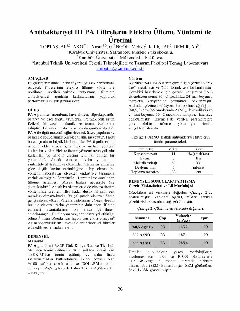
36
Antibakteriyel HEPA Filtrelerin Elektro Üfleme Yöntemi ile
Üretimi TOPTAŞ, Ali1,3, AKGÜL, Yasin2,3, GÜNGÖR, Melike3, KILIÇ, Ali3, DEMİR, Ali3.
1Karabük Üniversitesi Safranbolu Meslek Yüksekokulu, 2Karabük Üniversitesi Mühendislik Fakültesi,
3İstanbul Teknik Üniversitesi Tekstil Teknolojileri ve Tasarım Fakültesi Temag Laboratuvarı
AMAÇLAR
Bu çalışmanın amacı, nanolif yapılı yüksek performans
parçacık filtrelerinin elektro üfleme yöntemiyle
üretilmesi; üretilen yüksek performanslı filtrelere
antibakteriyel ajanlarla katkılandırma yapılarak
performansının iyileştirilmesidir.
GİRİŞ
PA-6 polimeri membran, hava filtresi, süperkapasitör,
batarya ve özel tekstil ürünlerini üretmek için üstün
fiziksel, kimyasal, mekanik ve termal özelliklere
sahiptir1. Literatür araştırmalarında da görülmüştür ki2,
PA-6 ile ilgili nanolifli ağlar üretmek üzere yapılmış ve
başarı ile sonuçlanmış birçok çalışma mevcuttur. Fakat
bu çalışmaların büyük bir kısmında3 PA-6 polimeri ile
nanolif elde etmek için elektro üretim yöntemi
kullanılmaktadır. Elektro üretim yöntemi uzun yıllardır
kullanılan ve nanolif üretimi için iyi bilinen bir
yöntemdir4. Ancak elektro üretim yönteminin
santrifüjle lif üretimi ve çözeltiden üfleme sistemlerine
göre düşük üretim verimliliğine sahip olması bu
yöntemi laboratuvar ölçekten endüstriye taşımakta
zorluk çekmiştir5. Santrifüjle lif üretimi ve çözeltiden
üfleme sistemleri yüksek hızları nedeniyle öne
çıkmaktadır6,7. Ancak bu sistemlerde de elektro üretim
yönteminde üretilen lifler kadar düşük lif çapı pek
mümkün olmamaktadır. Bu çalışmada elektro üfleme
geliştirilerek çözelti üfleme sisteminin yüksek üretim
hızı ile elektro üretim yönteminin daha ince lif elde
edilmesi avantajlarının bir araya getirilmesi
amaçlanmıştır. Bunun yanı sıra, antibakteriyel etkinliği
bilinen8 insan vücudu için hiçbir yan etkisi olmayan9
Ag nanopartiküllerin ilavesi ile antibakteriyel filtreler
elde edilmesi amaçlanmıştır.
DENEYSEL
Malzeme
PA-6 granülleri BASF Türk Kimya San. ve Tic. Ltd.
Şti.’nden temin edilmiştir. %85 saflıkta formik asit
TEKKİM’den temin edilmiş ve daha fazla
saflaştırılmadan kullanılmıştır. İkinci çözücü olan
%100 saflıkta asetik asit ise ISOLAB’dan temin
edilmiştir. AgNO3 tozu da Labor Teknik AŞ’den satın
alınmıştır.
Yöntem
Ağırlıkça %11 PA-6 içeren çözelti için çözücü olarak
%67 asetik asit ve %33 formik asit kullanılmıştır.
Çözeltiyi hazırlamak için çözücü karışımına PA-6
eklendikten sonra 50 °C sıcaklıkta 24 saat boyunca
manyetik karıştırıcıda çözünmesi beklenmiştir.
Ardından çözünen solüsyona katı polimer ağırlığının
%0,5, %2 ve %5 oranlarında AgNO3 ilave edilmiş ve
24 saat boyunca 50 °C sıcaklıkta karıştırıcı üzerinde
bekletilmiştir. Çizelge 1’de verilen parametrelere
göre elektro üfleme yöntemiyle üretim
gerçekleştirilmiştir.
Çizelge 1: AgNO3 katkılı antibakteriyel filtrelerin
üretim parametreleri.
Parametre Miktar Birim
Konsantrasyon 11 % (ağırlıkça)
Basınç 3 Bar
Elektrik voltajı 30 kV
Besleme hızı 5 ml/saat
Toplama mesafesi 50 cm
DENEYSEL SONUÇLAR/TARTIŞMA
Çözelti Viskoziteleri ve Lif Morfolojisi
Çözeltilere ait viskozite değerleri Çizelge 2’de
gösterilmiştir. Yapıdaki AgNO3 miktarı arttıkça
çözelti viskozitesinin arttığı görülmüştür.
Çizelge 2: Çözeltilerin viskozite değerleri.
Numune Çap Viskozite
(mPa.s) rpm
%0,5 AgNO3 R3 145,2 100
%2 AgNO3 R3 187,1 100
%5 AgNO3 R3 285,6 100
Üretilen numunelerin yüzey morfolojilerini
incelemek için 1.000 ve 10.000 büyütmelerle
TESCAN-Vega 3 modeli taramalı elektron
mikroskobu (SEM) kullanılmıştır. SEM görüntüleri
Şekil 1- 3’de gösterilmiştir.

37
Şekil 1: %0,5 AgNO3 içeren numunenin SEM
görüntüsü ve lif çapı dağılımı.
Çözeltideki PA-6 polimer miktarının %0,5 katı kadar
AgNO3 içeren numunenin ortalama lif çapı 89 ± 38 nm
iken %2 AgNO3 içeren numunenin ortalama lif çapı 94
± 47 nm’dir. AgNO3 miktarı, %5’ e çıkarıldığında ise
ortalama lif çapı 113 ± 55 nm’ye çıkmıştır.
Şekil 2: %2 AgNO3 içeren numunenin SEM
görüntüsü ve lif çapı dağılımı.
AgNO3, miktarının artmasıyla lif çapının artması
viskozitenin artması ile açıklanabilmektedir. Çünkü
viskozitedeki artış lif çapında artışa sebep olan önemli
bir etmendir.
Şekil 3: %5 AgNO3 içeren numunenin SEM
görüntüsü ve lif çapı dağılımı
Gümüş (Ag) nanopartiküllerin numunelerde varlığını
göstermek üzere gerçekleştirilen SEM-EDX
analizinde Ag pikleri görülmüştür.
Şekil 4: %5 AgNO3 içeren numunenin EDX analizi
sonuçları.
Hava geçirgenlik testi
ASTM D 737 standardı kullanarak hava geçirgenliği
testi uygulanan numunelerin değerleri Çizelge 3’de
verilmiştir. Her numune için 5 ölçüm yapılarak
ortalama değeri verilmiştir. Ortalama lif çapı arttıkça
artan gözenek büyüklüklerine bağlı olarak
numunelerin hava geçirgeliği de artmıştır.
Çizelge 3: AgNO3 katkılı numunelerin hava
geçirgenlikleri.
Numuneler Hava Geçirgenliği
(mm/s)
%0,5 AgNO3 27,2
%2 AgNO3 33
%5 AgNO3 44,2

38
Hava filtrasyonu performansı testi
Üretilen numunelere (TSI Model 8130A) model filtre
test santralinde hava filtrasyonu testleri yapıldı. Elde
edilen filtre test sonuçları Çizelge 4’de verilmiştir.
Çizelge 4: %0,5, %2 ve %5 AgNO3 katkılı
numunelerin filtre verimlilikleri.
Numuneler Basınç
mmH2
O
Verim
%
Kalite
Faktö
r
1/Pa
%0,5 AgNO3 9,5 99,21 0,51
%2 AgNO3 8,4 99,14 0,57
%5 AgNO3 6,5 98,61 0,66
Filtre performansı değerlendirilirken, penetrasyon
oranının yüksek, basınç düşüşünün az olması beklenir.
Bu minvalde, yani kalite faktörü açısından
değerlendirildiğinde en iyi filtrasyon performanslarını
%5 AgNO3 katkılı numune sahip olduğu 0.66 değerle
göstermiştir. Ortalama lif çapı artıkça kalite faktörü
artmaktadır. Çünkü filtreler daha kalındır, daha fazla
nanolif içerirler. Filtre malzemesindeki lif yoğunluğu
ve tutulan partiküllerin artması nedeniyle havanın
sıkışmasına ve çıkışta daha düşük bir basınca sahip
olmasına neden olmaktadır. Böylece basınç düşüşü
miktarı artmaktadır. Ancak ortalama lif çapı daha fazla
olduğu için liflerin oluşturduğu gözenek boyutları da
daha fazladır. Böylece daha küçük partiküllerin
penetrasyonu zorlaşmaktadır. Daha küçük lif çaplarında
penetrasyon oranı daha fazla olmaktadır.
Antibakteriyellik test sonuçları
PA-6 polimerine Ag nanopartiküllerinin eklenmesiyle
elde edilen numunelerin ve antibakteriyel özelliği
bilinen ancak yan etkiler nedeniyle tercih edilmeyen
triklosan damlatılmış referans numunenin E. coli ve S.
aureus bakterilerine karşı inhibisyon bölgelerinin
değerlendirilmesi yoluyla antibakteriyel etkisi
Şekil 5-7’ de gösterilmiştir.
S. Aureus bakterisine karşı etkinlik görülmemiştir.
Şekil 6’da görüldüğü üzere yalnızca %5 Ag katkılı
numune E. Coli bakterisi üzerinde diğer numunelere
göre daha az etkinlik göstermiştir. Bu sebeple %2 ve
%5 Ag katkılı numuneler için nonwoven üzerine
toplanan lif miktarı arttırılarak test tekrarlandı.
Numuneler elektro üfleme yöntemi ile 40 dk boyunca
üretildiler. Fakat miktarın artması S. Aureus bakterisi
için yine yeterli olmadı. Şekil 7’de görüldüğü üzere
yalnızca %5 Ag katkılı numune E. Coli bakterisi
üzerinde etkinlik gösterdi. Daha kalın numune eldesi
E. Coli’ye karşı inhibisyon alanını yaklaşık 2 cm
genişliğinde bir alana çıkardı. Daha yüksek inhibisyon
alanı için Ag nanopartiküllerinin oranının arttırılması
gerekmektedir.
Gram-negatif bakteriler (E. Coli), muhtemelen,
membran yükünden ve bakteri türlerinin ince veya
kompleks hücre duvarından kaynaklanan Gram-
pozitif (S. Aureus) bakterilerine kıyasla
nanokompozit filmler tarafından oldukça
baskılanmıştır. Genel olarak, Gram-pozitif bakteri
türleri, Gram-negatif bakterilerden üç boyutlu daha
kalın bir peptidoglikan (PG 20-80 nm) tabakasından
oluşur. PG katmanı, daha kısa peptitler ile çapraz
bağlanmış lineer polisakkarit zincirlerine sahiptir ve
bu nedenle Ag nanopartiküllerin Gram-pozitif
bakterilere nüfuz etmesini zorlaştıran karmaşık bir
yapı oluşturur. Ancak, Gram-negatif bakteriler,
negatif yüklü bir dış zar ve Ag nanopartiküllerin
penetrasyonunu kolaylaştıran ince PG katmanı (7-8
nm) ile kaplanır10.
Şekil 5: Farklı oranlarda Ag nanopartikülleri içeren
numunelerin S. aureus bakterisine karşı inhibisyon
bölgesi.
Şekil 6: Farklı oranlarda Ag nanopartikülleri içeren
numunelerin E. Coli bakterisine karşı inhibisyon
bölgesi.
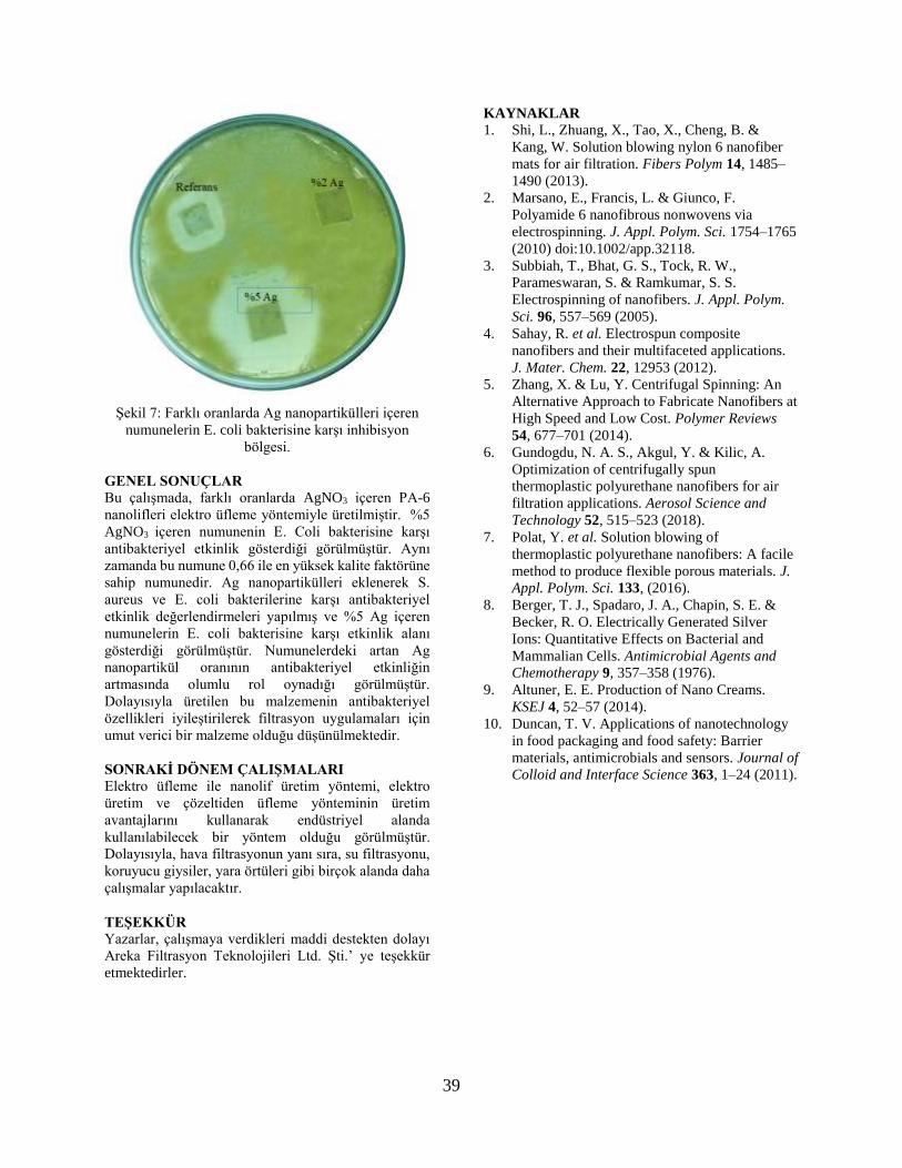
39
Şekil 7: Farklı oranlarda Ag nanopartikülleri içeren
numunelerin E. coli bakterisine karşı inhibisyon
bölgesi.
GENEL SONUÇLAR
Bu çalışmada, farklı oranlarda AgNO3 içeren PA-6
nanolifleri elektro üfleme yöntemiyle üretilmiştir. %5
AgNO3 içeren numunenin E. Coli bakterisine karşı
antibakteriyel etkinlik gösterdiği görülmüştür. Aynı
zamanda bu numune 0,66 ile en yüksek kalite faktörüne
sahip numunedir. Ag nanopartikülleri eklenerek S.
aureus ve E. coli bakterilerine karşı antibakteriyel
etkinlik değerlendirmeleri yapılmış ve %5 Ag içeren
numunelerin E. coli bakterisine karşı etkinlik alanı
gösterdiği görülmüştür. Numunelerdeki artan Ag
nanopartikül oranının antibakteriyel etkinliğin
artmasında olumlu rol oynadığı görülmüştür.
Dolayısıyla üretilen bu malzemenin antibakteriyel
özellikleri iyileştirilerek filtrasyon uygulamaları için
umut verici bir malzeme olduğu düşünülmektedir.
SONRAKİ DÖNEM ÇALIŞMALARI
Elektro üfleme ile nanolif üretim yöntemi, elektro
üretim ve çözeltiden üfleme yönteminin üretim
avantajlarını kullanarak endüstriyel alanda
kullanılabilecek bir yöntem olduğu görülmüştür.
Dolayısıyla, hava filtrasyonun yanı sıra, su filtrasyonu,
koruyucu giysiler, yara örtüleri gibi birçok alanda daha
çalışmalar yapılacaktır.
TEŞEKKÜR
Yazarlar, çalışmaya verdikleri maddi destekten dolayı
Areka Filtrasyon Teknolojileri Ltd. Şti.’ ye teşekkür
etmektedirler.
KAYNAKLAR
1. Shi, L., Zhuang, X., Tao, X., Cheng, B. &
Kang, W. Solution blowing nylon 6 nanofiber
mats for air filtration. Fibers Polym 14, 1485–
1490 (2013).
2. Marsano, E., Francis, L. & Giunco, F.
Polyamide 6 nanofibrous nonwovens via
electrospinning. J. Appl. Polym. Sci. 1754–1765
(2010) doi:10.1002/app.32118.
3. Subbiah, T., Bhat, G. S., Tock, R. W.,
Parameswaran, S. & Ramkumar, S. S.
Electrospinning of nanofibers. J. Appl. Polym.
Sci. 96, 557–569 (2005).
4. Sahay, R. et al. Electrospun composite
nanofibers and their multifaceted applications.
J. Mater. Chem. 22, 12953 (2012).
5. Zhang, X. & Lu, Y. Centrifugal Spinning: An
Alternative Approach to Fabricate Nanofibers at
High Speed and Low Cost. Polymer Reviews
54, 677–701 (2014).
6. Gundogdu, N. A. S., Akgul, Y. & Kilic, A.
Optimization of centrifugally spun
thermoplastic polyurethane nanofibers for air
filtration applications. Aerosol Science and
Technology 52, 515–523 (2018).
7. Polat, Y. et al. Solution blowing of
thermoplastic polyurethane nanofibers: A facile
method to produce flexible porous materials. J.
Appl. Polym. Sci. 133, (2016).
8. Berger, T. J., Spadaro, J. A., Chapin, S. E. &
Becker, R. O. Electrically Generated Silver
Ions: Quantitative Effects on Bacterial and
Mammalian Cells. Antimicrobial Agents and
Chemotherapy 9, 357–358 (1976).
9. Altuner, E. E. Production of Nano Creams.
KSEJ 4, 52–57 (2014).
10. Duncan, T. V. Applications of nanotechnology
in food packaging and food safety: Barrier
materials, antimicrobials and sensors. Journal of
Colloid and Interface Science 363, 1–24 (2011).

40
Grafen Katkılı Karbon Nanoliflerin Süperkapasitörlerde
Kullanımı ALTIN, Yasin*1, BEDELOĞLU, Ayşe**1
1Bursa Teknik Üniversitesi, Lif ve Polimer Mühendisliği Bölümü
* [email protected] ; ** [email protected]
AMAÇLAR
Esnek süperkapasitörler giyilebilir elektronik
uygulamalarının enerji ihtiyacının sağlanmasında
kullanılabilecek önemli enerji depolama
teknolojilerindendir. Karbon nanolifler esneklik,
hafiflik, geniş yüzey alanı gibi üstün özellikleri ile
süperkapasitörlerde elektrot olarak
kullanılabilmektedir. Bu elektrotların performansları
karbon bazlı nanomalzemeler (grafen, karbon nanotüp
vb), iletken polimerler ve metal oksit nanopartiküller ile
artırılabilmektedir. Bu çalışmada karbon nanolif
içerisine farklı oranlarda grafen ilave edilerek elde
edilen nanoliflerin morfolojik ve elektrokimyasal
özellikleri incelenmiştir.
GİRİŞ
Çevresel ve insan sağlığı gibi kaygılar nedeni ile enerji
üretiminde fosil yakıt kullanımı yerini güneş ve rüzgar
gibi yenilenebilir enerji kaynaklarına bırakmaktadır.
Fakat bu yenilenebilir enerji kaynakları çevresel
değişimlerden doğrudan etkilenen ve istendiği zaman
enerji üretiminin gerçekleştirilemediği sitemlerdir. Bu
yenilenebilir enerji kaynaklarının sürdürülebilir bir
şekilde kullanımı bu sitemlerin enerji depolama
sistemleri ile entegre edilmesi ile mümkün olmaktadır.
Diğer taraftan güneş pili, piezoelektrik ve triboelektrik
nanojeneratörler gibi enerji üretim sistemleri son
yıllarda tekstil yüzeylerine entegre edilmektedir. Bu
sistemlerden üretilen enerjinin verimli kullanımı ancak
üretilen enerjinin yine tekstil yüzeylerine uygulanabilen
sistemlerde depolanabilmesi ile mümkün olmaktadır.
Süperkapasitörler enerji depolama teknolojileri
arasında yüksek güç yoğunluğu, uzun döngü ömrü, hızlı
şarj/deşarj edilebilme gibi özellikleri ile ön plana
çıkmaktadır1-3. Süperkapasitörler elektrot, elektrolit,
ayırıcı ve akım toplayıcı tabakalardan oluşmaktadır.
Süperkapasitörler için en önemli komponenti
elektrotlar oluşturmaktadır. Aktif karbon, grafen,
karbon nanotüp gibi karbon bazlı malzemeler, iletken
polimerler ve metal oksitler süperkapasitörlerde
elektrot olarak kullanılmaktadır.
Karbon nanaolifler geniş yüzey alanı, mükemmel
elektriksel iletkenliği ve mekanik stabilitesi nedeni ile
çift tabakalı süperkapasitörlerde elektrot olarak
kullanılmaktadır. Uzun yıllardır bilinen bir malzeme
olan karbon nanoliflerin kapasitans özellikleri grafen,
karbon nanotüp gibi karbon bazlı nanomalzemeler veya
pseudokapasitif özellik gösteren metal oksit ve iletken
polimerlerin ilavesi ile geliştirilmektedir. Bu sayede
daha fazla enerji depolayabilen süperkapasitörler
üretilebilmektedir.
Bu çalışmada karbon nanolifler üretimi için çıkış
malzemesi olarak poliakrilonitril (PAN) polimeri
kullanılmıştır. Öncelikle PAN nanolif dokusuz
yüzeyleri elektroüretim yöntemi ile üretilmiş ve
sonrasında sırasıyla oksidasyon ve karbonizasyon
işlemlerine tabi tutularak karbon nanolifler elde
edilmiştir. Diğer taraftan PAN nanolif üretimi
öncesinde çözelti içerisine %1-20 arasında değişen
oranlarda grafen oksit (GO) ilave edilmiş ve
elektroüretim gerçekleştirilmiştir. Elde edilen GO
katkılı PAN nanolifler sırasıyla oksidasyon ve
karbonizasyon işlemlerine tabi tutulmuştur. Bu
işlemler sırasında PAN nanolifler karbon nanoliflere
dönüşürken aynı zamanda içerisine katkılanan grafen
oksit plakaları da inert atmosferde yüksek sıcaklıkta
indirgenerek grafene dönüşmektedir. Bu sayede
başarılı bir şekilde grafen katkılı karbon nanolif
yüzeyler elde edilmiştir.
DENEYSEL
Malzeme
Grafen oksit sentezi için grafit tozu Fisher
Scentific’ten, HCl (%33-35), H2SO4 (95–98%),
H3PO4 (85%) ve H2O2 (%30) Sigma Aldrich
(USA)’den temin edilmiştir. Nanolif üretimi için
dimetil formamid (DMF) ve dimetilsülfoksit (DMSO)
Sigma Aldrich (USA)’den, poliakrilonitril (PAN)
(MA: 150000 gr/mol) J&K Scientific’ten temin
edilmiştir. Tüm kimyasallar ilave bir saflaştırma
işlemi yapılmadan kullanılmıştır.
Yöntem
Grafen Oksit Sentezi: Grafen oksitin üretiminde
geliştirilmiş Hummer’s metodu kullanılmıştır4. 1 gr
grafit tozu, H2SO4/H3PO4 (120 ml/13,33 ml) karışımı
içerisine eklenerek manyetik karıştırıcı ile
karıştırılmış ve üzerine 6 gr KMnO4 ilave edilerek yağ
banyosu içerisinde 50 °C’de 12-24 saat boyunca
reaksiyona bırakılmıştır. Reaksiyon sonunda karışım
150 ml buz banyosu üzerine dökülerek üzerine 1 ml
%30’luk H2O2 ilave edilmiştir. Sonrasında karışım
içerisindeki katı malzeme santrifüj ile ayrılıp sırası ile
2 defa saf su, metanol, etanol, %37’lik HCl ile
yıkanmış sonrasında ise pH 7’ye gelene kadar saf su
ile yıkanmaya devam edilmiştir4.

41
Grafen Oksit Katkılı PAN Nanoliflerin Üretimi: Çalışma kapsamında grafen oksit farklı
konsantrasyonlarda (kütlece %1-20 arasında) PAN
çözeltisi içerisine katılarak GO oksit katkılı nanoliflerin
üretimi optimum elektroüretim şartlarında
gerçekleştirilmiştir.
Grafen/Karbon Nanoliflerin Üretimi: Üretilen grafen
katkılı nanolifler öncelikle 300 ⁰C’de hava ortamında
okside edilmiş, sonrasında ise argon ortamında tüp fırın
içerisinde 1000 ⁰C’de karbonize edilmiştir. PAN
nanoliflerin karbonizasyonu sırasında inert atmosferde
grafen oksit plakaları indirgenerek grafen plakalarına
dönüşmüştür.
DENEYSEL SONUÇLAR/TARTIŞMA
Grafen oksit geliştirilmiş Hummers’ metodu ile
sentezlenmiş ve sonrasında FT-IR ile karakterize
edilmiştir. Şekil 1’de çıkış malzemesi olarak kullanılan
grafit ve grafen oksidin FT-IR spektrumları
görülmektedir. Şekil 1’de görüldüğü üzere grafit
spektrumunda herhangi bir pik görülmezken
oksidasyon sonrasında GO’in oksidasyonunu gösteren
karakteristik pikler gözükmektedir.
Şekil 1. Grafit ve grafen oksidin FT-IR spektrumları
Şekil 2’de elde edilen GO katkılı PAN nanoliflerin
görüntüleri görülmektedir. %100 PAN nanolif beyaz
iken GO miktarı arttıkça rengi koyulaşmaktadır.
Şekil 2. Üretilen GO katkılı PAN nanoliflerin
görüntüsü.
Şekil 3’te ise oksidasyon ve karbonizasyon işlemi
sonrası numunelerin görüntüsü görülmektedir. Renk
değişimlerinden işlemlerin başarılı bir şekilde
gerçekleştirildi gözlemlenmekle birlikte FT-IR analizi
ile oksidasyon ve karbonizasyon işlemlerinin başarılı
bir şekilde gerçekleştirildiği teyit edilmiştir.
Şekil 3. GO katkılı PAN nanoliflerin oksidasyon ve
karbonizasyon sonrası görüntüleri.
Elde edilen grafen katkılı karbon nanoliflerin
elektrokimyasal özellikleri 3 elektrot sisteminde
CHI608E model cihaz ile gerçekleştirilmiştir.
Referans elektrot olarak Ag/AgCl, karşıt elektrot
olarak Pt elektrot kullanılmıştır. Elektrolit olarak ta 1
M’lık H2SO4 çözeltisi seçilmiştir.
Üretilen elektrotların elektrokimyasal özellikleri
ölçülmüş ve birbiri ile kıyaslanmıştır.
GENEL SONUÇLAR
Grafen oksit başarılı bir şekilde sentezlenerek PAN
nanoliflerin içerisine farklı oranlarda entegre
edilmiştir. Elde edilen nanokompozit nanolifler
başarılı bir şekilde karbonize edilerek grafen katkılı
karbon nanolifler üretilmiştir. Üretilen nanokompozit
elektrotların morfolojik ve elektrokimyasal özellikleri
incelenmiştir.
TEŞEKKÜR/BILGILENDIRME/FON
KAYNAĞI
Bu çalışma Bursa Teknik Üniversitei Bilimsel
Araştırma Projesi (BAP) No:172D32 tarafından
desteklenmiştir.
KAYNAKLAR
1. Wang, G.P., L. Zhang, and J.J. Zhang, 2012, “A
review of electrode materials for electrochemical
supercapacitors”. Chemical Society Reviews. 41(2):
p. 797-828.
2. Chee, W.K., et al., 2016, “Flexible Graphene-
Based Supercapacitors: A Review”. Journal of
Physical Chemistry C. 120(8): p. 4153-4172.
3. Zang, X.B., et al., 2015, “Graphene/polyaniline
woven fabric composite films as flexible
supercapacitor electrodes”. Nanoscale. 7(16): p.
7318-7322.
4. Marcano, D.C., et al., 2010, “Improved Synthesis
of Graphene Oxide”. Acs Nano. 4(8): p. 4806-4814.
42
Usage of Polyacrylonitrile Nanofibers Containing MgO
Nanoparticles on Particulate Filtration and Toluene
Adsorption DEMIR, Ali1, BAYSAL, Tugba2,3
1 Department of Textile Engineering, Istanbul Technical University 2 Department of Nanoscience and Nanoengineering, Istanbul Technical University 3 Department of Nanoscience and Nanoengineering, Gebze Technical University
PURPOSE
The aim of this study is to investigate the use of MgO
/ PAN nanofibers in air filtration and to investigate
the effect of MgO nanoparticles and their different
concentrations on both particle holding efficiency
and toluene adsorption ability.
INTRODUCTION
Due to the increasing population, increasing
industrialization and millions of vehicles of
transportation, very fine dust particles and gases are
emitted into the environment. As a result, air quality
has been decreasing day by day. In addition, there
are volatile organic compounds (VOCs), many of
which can be evaporated even at room temperature,
in many materials such as adhesives, air fresheners,
glues, paints, liquid cleaners, floor polishes,
solvents, which we frequently use in our daily lives.
Although most of these affects mainly the
respiratory system, they can cause hematological
problems and even cancer. Toluene, benzene,
formaldehyde, xylene and styrene are among the
major VOCs [1].
The holding of these gaseous substances is achieved
by adsorption. For this purpose, an adsorbent with a
high surface area, a suitable pore size (micro-meso
pores) and distribution and which will able to
interact with VOCs chemically or physically is
required [2]. Considering all these properties,
functionalized nanofibers are a good filter material
that can be used in both VOCs adsorption and
particulate filtration studies with their superior
properties such as high surface areas, porosity and
being easily combined with many materials [3].
Metal oxides such as MgO, Al2O3, SnO2, MnO,
TiO2, ZnO and their nanoparticle (NP) forms can
chemically react with toxic gases in the air and
convert them to harmless or less harmful by-
products due to their catalytic properties [4]. Metal
oxides especially in the form of nanoparticles,
exhibit more catalytic properties due to their high
surface area, higher number of reactive oxide /
hydroxide ions on the surface, and structural surface
defects [5]. Furthermore, the added nanoparticles
increase the surface area by causing protrusions on
the nanofiber surface and, also cause to reduce the
pore size. This increases both filtration performance
and adsorption capability [6].
In this study, we added MgO NPs at various
concentrations to PAN polymer solution to produce
functional nanofibers and demonstrated the effect of
MgO NPs and their concentration on both particle
holding efficiency and toluene adsorption ability.
EXPERIMENTAL STUDIES
Materials
Industrial PAN powder (AKKIM),
dimethylformamide (DMF) as a solvent and MgO
NPs (Sigma Aldrich) was used during our study.
Fabrication of PAN Nanofiber Containing MgO
Nanoparticles
First, the MgO NPs in the various contents (7 wt%,
17 wt%) was added into DMF, then the solution is
stirred for 1 hour with the ultrasonic stirrer. Then,
13%wt of PAN powder (it keeps constant for all
solutions) was dissolved in the mixture solution of
the DMF-MgO NPs by using magnetic stirrer for 6
hours.
The MgO/PAN filter media was fabricated onto a
non-woven PP support (25 csm) by electrospinning
device with 2 needles. The distance from the needle
tip to the collector, the voltage, flow rate,
homogeneity and drum speed were set at 23 cm, 26
kV, 2.2 ml/h, 20 mm/s – 90 mm, and 200 rpm
respectively.
Particulate Filtration Test/Toluene Adsorption
Test
An automated filter tester (model 8130A) was used
to evaluate the filtration performance of the
MgO/PAN filter samples. Charge-neutralized

43
monodisperse solid sodium chloride (NaCl) aerosol
particles with diameter size of 300−500 nm was used
as an ultra-fine particle agent.
Toluene gas adsorption studies were carried out
using the test setup established in ITU environmental
laboratory (Figure 1). Toluene gas was sent into
filter media at constant speed, the existing toluene
gases were collected and analysed by GC-MS. The
Scanning Electrone Microscopy (SEM) was used for
morphological characterisation.
Figure 1 Toluene gas adsorption test setup
EXPERIMENTAL RESULTS AND
DISCUSSION
The surface morphology of MgO NP free PAN NF,
%20 MgO/PAN NF (%13 PAN and %7 MgO NP),
and %30 MgO/PAN NF (%13 PAN and %17 MgO
NP) at certain coating times of 20,40 and 60 mins, is
depicted in Figure 2.
Figure 2 SEM images of produced samples (scale
bar is 5 μm and magnification:5 kx for all images)
According to SEM results, 13% PAN NFs are
smooth, flat, and they have uniform fiber
morphology with no bead formation. Although MgO
NPs were generally homogeneous spread on the
nanofiber surface, agglomeration of MgO NPs
occurs in some regions. Increase in MgO NPs
content in filter media cause to increase roughness of
nanofibrous surface. These nanoprotrusions cause to
decrease in pore size between the nanofibers.
Figure 3 Average fiber size of produced samples
As seen in Figure 3, size of nanofibers increases with
increasing MgO NPs content into polymer solution
related to increased viscosity of solution.
In Figure 4, Filtration efficiency and pressure drop
results of produced samples is shown. It is known
that, as the fibre diameter of nanofiber decreases, its
pore size and porosity decreases. When pore size
reduces, filtration efficiency and pressure drop
increases [7]. In our study, as the MgO NPs content
into polymer solution increased, the fiber diameter
decreased. However, pore diameters decreased as the
added nanoparticles caused protrusions on the
surface. So, filtration efficiency and pressure drop
increases related to increased filter thickness and
increased nanoparticle concentration (Figure 4).
Figure 4 Thickness and nanoparticle
concentration effect on filtration Efficiency
(above) and pressure drop (below)
0
200
400
600
%13 PAN NF %20 MgO/PAN
NF
%30 MgO/PAN
NF
332
472555
Fiber size (nm)

44
Figure 5. Nanoparticle Concentration Effect on Toluene Adsorption
Toluene adsorption test results of produced samples
are shown in Figure 5. According to results, As the
concentration of MgO NPs increases, the amount of
adsorbed toluene onto samples increases. This is
related to the pore size. As mentioned above, after
addition of MgO NPs into solution, the pore size
among nanofibers decreased and, thus adsorption
ability increases. In our study, we hoped to see the
catalytic effect of MgO NPs. Unfortunately, we were
only able to achieve toluene adsorption, no harmless
by-product formation was observed. Moreover, we
can say that as the coating time increases, the amount
of adsorbed toluene onto samples increases. As the
coating time increases, the thickness of the filter
media produced increases and micro-meso channels
form in the structure, and the nanoparticles may find
more space for adsorption.
CONCLUSIONS
In our study, we added MgO NPs to the polymer
solution, thus we obtained a rough surface. As the
formed protrusions reduced pore sizes, the filtration
efficiency and pressure drop of the filters produced
increased, but also caused a large increase in the
amount of toluene adsorption. Due to the catalytic
properties of MgO NPs we expected to break down
toluene and convert it to harmless by-products.
Unfortunately, we could not obtain catalytic
degradation products at the MgO NP concentration
studied. However, we were able to capture ultra-fine
particles with a high yield of 96.2%, a pressure drop
of 253 Pa. In addition, we have demonstrated that
nanofibers are a promising material for gas filtration.
We were able to adsorb 44.4% of toluene, a harmful
gas.
FUTURE STUDIES
We aim to produce MgO / PAN NF with higher MgO
content, so that we can see the catalytic effect of
MgO NPs.
REFERENCES
[1] M. Kampa and E. Castanas, ‘Human health
effects of air pollution’, Environ. Pollut., vol.
151, no. 2, pp. 362–367, Jan. 2008, doi:
10.1016/j.envpol.2007.06.012.
[2] X. Zhang, B. Gao, A. E. Creamer, C. Cao, and
Y. Li, ‘Adsorption of VOCs onto engineered
carbon materials: A review’, J. Hazard.
Mater., vol. 338, pp. 102–123, Sep. 2017, doi:
10.1016/j.jhazmat.2017.05.013.
[3] M. Zhu et al., ‘Electrospun Nanofibers
Membranes for Effective Air Filtration’,
Macromol. Mater. Eng., vol. 302, no. 1, p.
1600353, Jan. 2017, doi:
10.1002/mame.201600353.
[4] A. Vanangamudi, S. Hamzah, and G. Singh,
‘Synthesis of hybrid hydrophobic composite
air filtration membranes for antibacterial
activity and chemical detoxification with high
particulate filtration efficiency (PFE)’, Chem.
Eng. J., vol. 260, pp. 801–808, Jan. 2015, doi:
10.1016/j.cej.2014.08.062.
[5] S. Dadvar, H. Tavanai, M. Morshed, and M.
Ghiaci, ‘The Removal of 2-Chloroethyl Ethyl
Sulfide Using Activated Carbon Nanofibers
Embedded with MgO and Al 2 O 3
Nanoparticles’, J. Chem. Eng. Data, vol. 57,
no. 5, pp. 1456–1462, May 2012, doi:
10.1021/je201328s.
[6] J. Su, G. Yang, C. Cheng, C. Huang, H. Xu,
and Q. Ke, ‘Hierarchically structured
TiO2/PAN nanofibrous membranes for high-
efficiency air filtration and toluene
degradation’, J. Colloid Interface Sci., vol.
507, pp. 386–396, 2017.
[7] H.-J. Choi et al., ‘Filtration Properties of
Nanofiber/Microfiber Mixed Filter and
Prediction of its Performance’, Aerosol Air
Qual. Res., vol. 17, no. 4, pp. 1052–1062,
2017, doi: 10.4209/aaqr.2016.06.0256.

45
Interaction of Phosphate-Buffered Saline on the Surface of
Carbon Nanofiber Electrodes SAHTANİ Karima1, ALADAĞ TANİK Nilay1, AYKUT Yakup1,2
1Bursa Uludag University, Graduate School of Natural and Applied Sciences, Textile Engineering, 16059, Nilufer,
Bursa, Turkey 2Bursa Uludag University, Engineering Faculty, Department of Textile Engineering, 16059, Nilufer, Bursa, Turkey
OBJECTIVES
Investigation of the interaction of PBS solution with
carbon nanofibers surface since PBS will be used for
dissolving miRNA molecules to immobilize them on
carbon nanofiber surface or the solution will be used as
electrochemical measurement medium.
INTRODUCTION
Nanofibers are great materials because of their high
specific surface area and very applicable for variety of
applications such as energy1,2, environment3,
biomedical4 and biosensors5. Electrospinning is a
feasible technology to produced nanofibrous mat
structure by using very broad spectrum of the materials
including polymers6, ceramic7, carbon8 and composites 2.
Carbon nanofibers are produced from an electrospun
polymer precursor such as polyacrylonitrile9, polyvinyl
alcohol10,11, lignin12, etc. The precursor nanofibers are
properly thermally treated to convert them into carbon
nanofiber structures13. Most of the electrospun carbon
nanofibers have been produced by using PAN as a
precursor polymer in the literature for very diverce
applications such as energy storage8, oil-water
separation14, biosensors15, etc.
Carbon based electrodes are used as the working
electrodes for electrochemical biosensor analysis of
genetic molecules16,17. Since carbon nanofibers have
very high specific surface are, more molecules can be
interact on the surface and biosensor device
performance could be enhanced.
In order to immobilize genetic molecules on the
surfaces of the electrodes for electrochemical
characterization, in some studies, first the genetic
molecules were dissolved in PBS and then the prepared
dissolution were applied on the surface of the electrode,
or the solution is used as electrochemical measurement
medium18–20.
Carbon nanofibers are potential candidate as working
electrode for electrochemical miRNA biosensor
applications. So, the interaction of PBS and the
electrode surface should be taken into consideration.
Based on this motivation, in this study, carbon
nanofibers were produced with the addition of
hemoglobin and lawsone in the PAN/DMF
electrospinning solutions. As-spun precursor
nanofibers were heat treated for a proper
carbonization. Finally, SEM and contact angle
measurements with PBS were carried out.
EXPERIMENTAL
Materials
Polyacrylonitrile (average Mw 150000, Sigma
Aldrich), N,N-Dimethylformamide, hemoglobin,
lawsone, phosphate-buffered saline.
Method
8 wt. % of PAN dissolved in N,N-
Dimethylformamide by magnetic stirring. A defined
amount of hemoglobin and lawsone were added into
the prepared solution separately and stirred for 24
hours. “L” refers to Lawsone and “H” refers to
Hemoglobin, and the number with the letter “L” and
“H” refers to weight percentage of lawsone respect to
PAN in the electrospinning solution (ex: L15 means
15 wt.% PAN in 8 wt. % PAN/DMF). Then, the
prepared solutions were electrospun into the precursor
nanofibrous mat. Electrospinning conditions were
adjusted as 12 kV applied voltage, 0.5 ml/hours
feeding rate, and 15 cm from the tip of needle to
collector. The precursor nanofibers stabilized in air
atmosphere at 280oC for 1 hour and then carbonized
in nitrogen atmosphere at 800 oC for 2 hours21,22.
After morphological analyzes with a scanning
electron microscope, contact angle measurements
were conducted by dropping PBS on the carbon
nanofibrous mat surfaces.
EXPERIMENTAL RESULTS/DISCUSSION
Precursor electrospun PAN nanofibers were
stabilized and carbonized sequentially as it was
explained in the experimental section. Carbonized
nanofiber morphologies were inspected by observing
SEM images. As seen from Figure 1, carbonized
nanofibers were very well randomly distributed in the
mat structure and fibers uniformity hasn’t been lost.
Even though some beaded structures are presented on
the carbonized fibers, these defects are not seen all
around the web.

46
Figure 1. SEM image of neat carbon nanofiber surface.
Different amount of lawsone was added into
electrospun PAN/DMF solution, and PAN/lawsone
precursor nanofibers were obtained after a proper
electrospinning process. As-spun precursor
PAN/lawsone nanofibers were also stabilized and
carbonized sequentially bu following the same
procedure. The morphologies of lawsone added
carbonized PAN nanofibers were observed with SEM
microscopy and the results are given in Figure 2.
Figure 2. SEM image of lawsone added (in precursor
PAN NFs) carbon nanofiber surface: (A) L15, (B)
L30, (C) L70 ve (D) L100.
As seen from Figure 2, when a small amount of lawsone
was presented in the precursor solution, very much bead
structures (called bead-on-a-string23) are presented on
and among the fibers. When the amount of lawsone was
increased in the precursor solution, beaded morphology
turned the uniform nanofibers structures.
Figure 3. SEM image of hemoglobin added (in
precursor PAN NFs) carbon nanofiber surface:
(A)H0.5, (B) H1, (C) H3, (D) H15 ve (E) H30.
As seen in Figure 3, when hemoglobin powder was
added into the precursor electrospinning solution,
beaded defect structure was also seen in the mat
structures. The amount of beaded structure is not
stable with the hemoglobin concentration that could
be related the solution preparation time and condition
since 24 hours were not enough to obtain a proper
solution after adding hemoglobin in the solution.
Some hemoglobin particles were not dissolved and
precipitated in the syringe during the electrospinning
process.
Figure 4. PBS çözeltisi kullanılarak saf karbon nanolif
yüzeydeki temas açısı ölçüm sonucu.
Figure 5. PBS çözeltisi kullanılarak lawsone katkılı
karbon nanoliflerde temas açısı ölçüm sonuçları: (A)
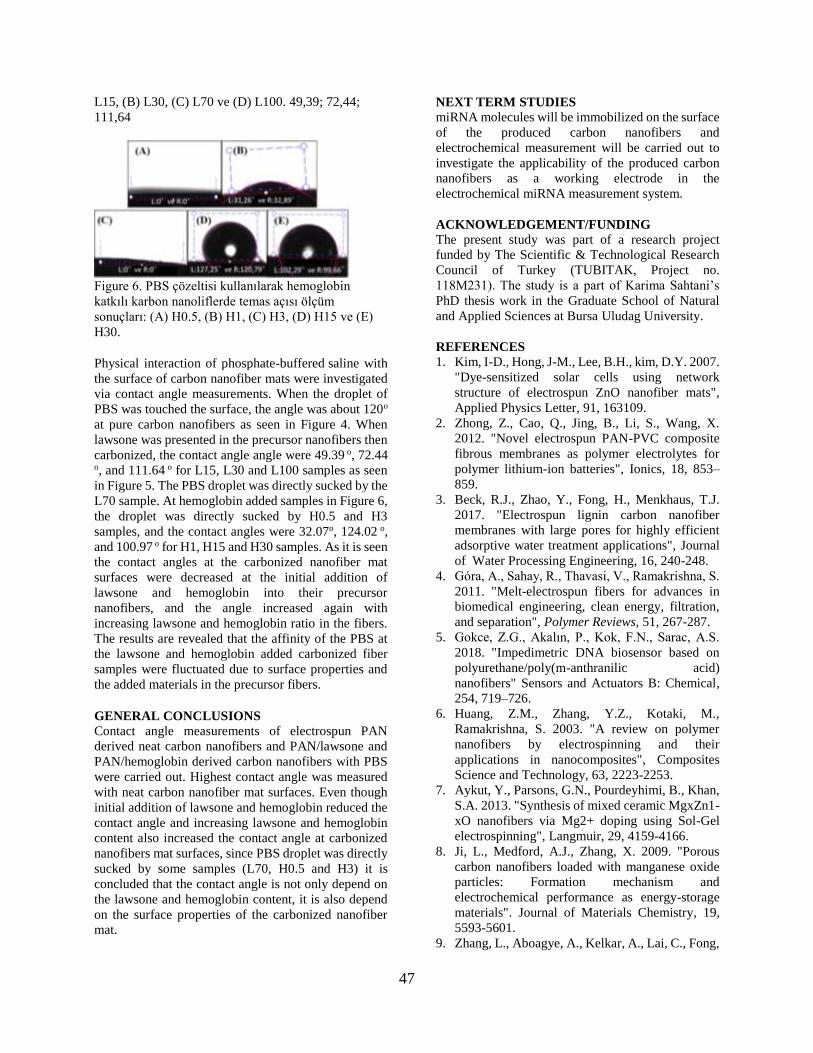
47
L15, (B) L30, (C) L70 ve (D) L100. 49,39; 72,44;
111,64
Figure 6. PBS çözeltisi kullanılarak hemoglobin
katkılı karbon nanoliflerde temas açısı ölçüm
sonuçları: (A) H0.5, (B) H1, (C) H3, (D) H15 ve (E)
H30.
Physical interaction of phosphate-buffered saline with
the surface of carbon nanofiber mats were investigated
via contact angle measurements. When the droplet of
PBS was touched the surface, the angle was about 120o
at pure carbon nanofibers as seen in Figure 4. When
lawsone was presented in the precursor nanofibers then
carbonized, the contact angle angle were 49.39 o, 72.44
o, and 111.64 o for L15, L30 and L100 samples as seen
in Figure 5. The PBS droplet was directly sucked by the
L70 sample. At hemoglobin added samples in Figure 6,
the droplet was directly sucked by H0.5 and H3
samples, and the contact angles were 32.07o, 124.02 o,
and 100.97 o for H1, H15 and H30 samples. As it is seen
the contact angles at the carbonized nanofiber mat
surfaces were decreased at the initial addition of
lawsone and hemoglobin into their precursor
nanofibers, and the angle increased again with
increasing lawsone and hemoglobin ratio in the fibers.
The results are revealed that the affinity of the PBS at
the lawsone and hemoglobin added carbonized fiber
samples were fluctuated due to surface properties and
the added materials in the precursor fibers.
GENERAL CONCLUSIONS
Contact angle measurements of electrospun PAN
derived neat carbon nanofibers and PAN/lawsone and
PAN/hemoglobin derived carbon nanofibers with PBS
were carried out. Highest contact angle was measured
with neat carbon nanofiber mat surfaces. Even though
initial addition of lawsone and hemoglobin reduced the
contact angle and increasing lawsone and hemoglobin
content also increased the contact angle at carbonized
nanofibers mat surfaces, since PBS droplet was directly
sucked by some samples (L70, H0.5 and H3) it is
concluded that the contact angle is not only depend on
the lawsone and hemoglobin content, it is also depend
on the surface properties of the carbonized nanofiber
mat.
NEXT TERM STUDIES
miRNA molecules will be immobilized on the surface
of the produced carbon nanofibers and
electrochemical measurement will be carried out to
investigate the applicability of the produced carbon
nanofibers as a working electrode in the
electrochemical miRNA measurement system.
ACKNOWLEDGEMENT/FUNDING
The present study was part of a research project
funded by The Scientific & Technological Research
Council of Turkey (TUBITAK, Project no.
118M231). The study is a part of Karima Sahtani’s
PhD thesis work in the Graduate School of Natural
and Applied Sciences at Bursa Uludag University.
REFERENCES
1. Kim, I-D., Hong, J-M., Lee, B.H., kim, D.Y. 2007.
"Dye-sensitized solar cells using network
structure of electrospun ZnO nanofiber mats",
Applied Physics Letter, 91, 163109.
2. Zhong, Z., Cao, Q., Jing, B., Li, S., Wang, X.
2012. "Novel electrospun PAN-PVC composite
fibrous membranes as polymer electrolytes for
polymer lithium-ion batteries", Ionics, 18, 853–
859.
3. Beck, R.J., Zhao, Y., Fong, H., Menkhaus, T.J.
2017. "Electrospun lignin carbon nanofiber
membranes with large pores for highly efficient
adsorptive water treatment applications", Journal
of Water Processing Engineering, 16, 240-248.
4. Góra, A., Sahay, R., Thavasi, V., Ramakrishna, S.
2011. "Melt-electrospun fibers for advances in
biomedical engineering, clean energy, filtration,
and separation", Polymer Reviews, 51, 267-287.
5. Gokce, Z.G., Akalın, P., Kok, F.N., Sarac, A.S.
2018. "Impedimetric DNA biosensor based on
polyurethane/poly(m-anthranilic acid)
nanofibers" Sensors and Actuators B: Chemical,
254, 719–726.
6. Huang, Z.M., Zhang, Y.Z., Kotaki, M.,
Ramakrishna, S. 2003. "A review on polymer
nanofibers by electrospinning and their
applications in nanocomposites", Composites
Science and Technology, 63, 2223-2253.
7. Aykut, Y., Parsons, G.N., Pourdeyhimi, B., Khan,
S.A. 2013. "Synthesis of mixed ceramic MgxZn1-
xO nanofibers via Mg2+ doping using Sol-Gel
electrospinning", Langmuir, 29, 4159-4166.
8. Ji, L., Medford, A.J., Zhang, X. 2009. "Porous
carbon nanofibers loaded with manganese oxide
particles: Formation mechanism and
electrochemical performance as energy-storage
materials". Journal of Materials Chemistry, 19,
5593-5601.
9. Zhang, L., Aboagye, A., Kelkar, A., Lai, C., Fong,

48
H. 2014. "A review: Carbon nanofibers from
electrospun polyacrylonitrile and their
applications", Journal of Materials Science, 49,
463–480.
10. Gupta, A., Dhakate, S.R. 2017. "Development of
structurally stable electrospun carbon nanofibers
from polyvinyl alcohol", Materials Research
Express, 4, 045021.
11. Xuyen, N.T., Ra, E.J., Geng, H.Z., Kim, K.K., An,
K.H., Lee, Y.H. 2007, "Enhancement of
conductivity by diameter control of polyimide-
based electrospun carbon nanofibers", The Journal
of Physical Chemistry B, 111, 11350-11353.
12. Ma, X., Kolla, P., Zhao, Y., Smirnova, A.L., Fong,
H. 2016. "Electrospun lignin-derived carbon
nanofiber mats surface-decorated with MnO2
nanowhiskers as binder-free supercapacitor
electrodes with high performance", Journal of
Power Sources, 325, 541-548.
13. Aykut, Y., Pourdeyhimi, B., Khan, S.A. 2013.
"Effects of surfactants on the microstructures of
electrospun polyacrylonitrile nanofibers and their
carbonized analogs", Journal of Applied Polymer
Science, 130, 3726-3735.
14. Tai, M.H., Gao, P., Tan, B.Y.L., Sun, D.D., Leckie,
J.O. 2014. "Highly efficient and flexible electrospun
carbon-silica nanofibrous membrane for ultrafast
gravity-driven oil-water separation", ACS Applied
Materials and Interfaces, 6, 9393-9401.
15. Liu, D., Zhang, X., You, T. 2014. "Electrochemical
performance of electrospun free-standing nitrogen-
doped carbon nanofibers and their application for
glucose biosensing", ACS Applied Materials and
Interfaces, 6, 6275-6280.
16. Congur, G., Eksin, E., Erdem, A. 2015.
"Impedimetric Detection of microRNA at Graphene
Oxide Modified Sensors", Electrochimica Acta,
172, 20-27.
17. Karimi-Maleh, H., Tahernejad-Javazmi, F., Atar,
N., Yola, M.L., Gupta, V.K., Ensafi, A.A. 2015. "A
Novel DNA biosensor based on a pencil graphite
electrode modified with polypyrrole/functionalized
multiwalled carbon nanotubes for determination of
6-mercaptopurine anticancer drug", Industrial
Engineering Chemistry Research, 2015, 54, 3634–
3639.
18. Kara, P., Kerman, K., Ozkan, D., Meric, B., Erdem,
A., Ozkan, Z., Ozsoy, M. 2002. "Electrochemical
genosensor for the detection of interaction between
methylene blue and DNA", Electrochemistry
Communications, 4, 705-709.
19. Shen, H.Y., Zheng, H.M., Zhu, N., Liu, Y.Q., Gao,
J., Li, J. 2010. "Electrochemical investigation of
DNA interaction with melamine and its related
compounds", International Journal of
Electrochemical Science, 5, 1587-1596.
20. Tanik, N.A., Demirkan, E., Aykut, Y. 2018.
"Guanine oxidation signal enhancement in DNA
via a polyacrylonitrile nanofiber-coated and cyclic
voltammetry-treated pencil graphite electrode",
Journal of Physics and Chemisty of Solids, 118,
73-79.
21. Pirzada, T., Arvidson, S.A., Saquing, C.D., Shah,
S.S., Khan, S.A. 2014. "Hybrid carbon silica
nanofibers through sol-gel electrospinning",
Langmuir, 51, 15504-15513.
22. Aykut, Y. 2013. "Electrospun MgO-loaded
carbon nanofibers: Enhanced field electron
emission from the fibers in vacuum", Journal of
Physics and Chemistyr of Solids, 74, 328-337.
23. Lin, T., Wang, H., Wang, H., Wang, X. 2004.
"The charge effect of cationic surfactants on the
elimination of fibre beads in the electrospinning of
polystyrene", Nanotechnology, 15, 1375.

49
Understanding the Electrospinnability of Polyvinyl Alcohol
(PVA) and Controlled Release of Curcumin Through the
Electrospun Mat MAHMUD, Md Musavvir 1, PARVEEN, Asma 2, ZAMAN, Sumaiya 3, JAHAN, Rumana A4, ARAFAT, M Tarik* 1
1Department of Biomedical Engineering, Bangladesh University of Engineering and Technology (BUET), Dhaka,
Bangladesh, 2Department of Mechanical Engineering, Nazarbayev University, Astana, Kazakhstan,
3Department of Microbiology, University of Dhaka, Dhaka, Bangladesh, 4Centre for Advanced Research in Sciences (CARS), University of Dhaka, Dhaka 1000, Bangladesh.
INTRODUCTION
Electrospinning offers to fabricate fibers of various
sizes and shape from both natural and synthetic
polymers. The electrospinning process can be applied
to a wide range of applications of various fields because
of the high surface-to-volume ratio and easily tunable
morphology of electrospun fibers. Polyvinyl alcohol
(PVA) is a biocompatible and highly hydrophilic
polymer which has also numerous applications.
Curcumin is a natural antibacterial chemical extracted
from the spice turmeric. In this study, at first PVA
solutions were prepared using different binary solvent
mixtures to study the spinnability of PVA in non-water
solvent as curcumin is not soluble in water. Tea’s graph
was introduced to map the solubility and spinnability of
the prepared solutions. After optimizing the solvent,
PVA/curcumin solution was prepared in an appropriate
solvent and electrospun. To stabilize the PVA/curcumin
electrospun mats, physical crosslinking was carried out
by heat treatment at different temperatures and UV-
exposure for a different period. The crosslinking also
ensured the controlled release of curcumin from the
electrospun fiber mats. All the electrospun fiber mats
were evaluated with a scanning electron microscope
(SEM), X-ray diffraction (XRD), Fourier transform
infrared spectroscopy (FTIR) and differential scanning
calorimetry (DSC). Finally, the antibacterial efficacy of
the electrospun PVA/curcumin was evaluated by
antibacterial test.
EXPERIMENTAL
Method
7%, 10% and 15% (w/v) PVA solutions were prepared
in water, 20% acetic acid, 50% acetic acid, 20% ethanol
and 50% ethanol and the corresponding solutions were
electrospun. Solubility and spinnability of the solutions
were mapped with Tea’s graph. Furthermore, 10% PVA
solutions with 1%, 2% and 5% curcumin (w/w with
respect to PVA) were prepared to investigate the drug
release. To stabilize in aqueous medium and control the
release of curcumin the PVA/curcumin fiber mats were
crosslinked by heat treatment and UV-exposure. Heat
treatment was carried out at 80 ˚C, 120˚C and 160˚C
for 2 hours. On the other hand, UV-exposure was
carried out at 40W for 30 minutes, 1 hr and 2 hr. Drug
release study was carried out in phosphate buffer
saline (PBS) for 24 hours. The antibacterial test was
carried out against E. coli and S. aureus to evaluate
the antibacterial properties of curcumin.
EXPERIMENTAL RESULTS AND
DISCUSSIONS
The study reveals that the morphology of electrospun
PVA fibers from different binary solvent mixtures
differs significantly from each other. While solutions
prepared with acetic acid-water binary solvent
mixture (AW) and water produce cylinder-shaped
fibers, solutions prepared with ethanol-water binary
solvent mixture (EW) produce flat-shaped fibers.
Diameters of fibers spun from AW solutions exhibit
the smallest diameter in the range of 70-238 nm. On
the other hand, the diameter of fibers spun from EW
solutions was much higher in the range of 270-955
nm. However, adding curcumin with PVA decreases
the average fiber diameter. The more curcumin was
added, the more decrease in diameter was observed.
Crosslinking by heat treatment caused a marginal
increase in fiber diameter whereas no significant
change was observed in the case of UV-exposure. The
controlled release of curcumin was achieved by both
types of crosslinking. The release of curcumin was
slowed down up to 20% by heat treatment and 9% by
UV-exposure at 24 hr. The antibacterial study showed
all bacteria killed within 6 hours.
CONCLUSIONS
Electrospinning of PVA from binary solvent mixtures
was evaluated and utilized in drug delivery
application where curcumin was used as an
antibacterial drug. Fibers of different sizes and shapes
were fabricated by using different solvents. While
incorporating curcumin, it was successfully
electrospun with PVA and crosslinked by heat
treatment and UV-exposure. The controlled release of
curcumin was achieved by both types of crosslinking.
50
Excellent antibacterial properties were also observed. It
is expected that the stable antibacterial nanofibrous mat
with controlled curcumin release capability could be a
potential candidate for wound dressing application.

51
Nanolif Esaslı Piezoelektrik Nanojeneratörlerde
Elektrosprey Yoluyla Elektrot Uygulamaları ÜNSAL, Ömer Faruk1, ÇELİK BEDELOĞLU, Ayşe2
1Bursa Teknik Üniversitesi, İleri Teknolojiler A.B.D, Yıldırım/Bursa,Türkiye 2Bursa Teknik Üniversitesi, Lif ve Polimer Mühendisliği Bölümü, Yıldırım/Bursa,Türkiye
[email protected], [email protected]
AMAÇLAR
Bu çalışmanın amacı, elektrosprey metodu ile iletken
partikül kaplanması ve kaplamaların mekanik-
elektriksel enerji dönüşümündeki performansının
incelenmesidir. Üretilen nanojeneratör sistemlerden
alınan çıkış voltajları ele alınarak elektrotların
kalınlıkları ile performansları arasındaki ilişki
belirlenmiştir.
GİRİŞ
Nanojeneratörler, verimsiz kullanılan, yani atık
durumdaki mekanik veya ısıl enerjinin geri kazanımını
sağlayan sistemlerdir1. Mekanik enerjinin elektrik
enerjisine dönüşüm mekanizmasında itici güç olarak
yer değiştirme akımı kullanılmaktadır2.
Nanojeneratörler isimlerini üretilen çok küçük enerji
miktarlarından almaktadırlar; üretildikleri
materyallerin nano-malzeme olma şartı yoktur.
Nanojeneratörler piezoelektrik, triboelektrik veya
piroelektrik prensiple çalışırlar. Piezoelektrik ve
triboelektrik nanojeneratörler mekanik enerjinin
dönüşümünü sağlarken piroelektrik nanojeneratörler
ısıl enerjinin elektrik enerjisine dönüşmesini sağlar3.
Piezoelektrik etki, moleküler simetri eksikliğinden
kaynaklanan ve mekanik stres altında gerçekleşen
polarizasyondan kaynaklanmaktadır4. Bu bağlamda en
çok kullanılan piezoelektrik malzemeler würtzite
kristaller, perovskit kristaller ve polimerlerdirler.
Piezoelektrik etki kullanılarak üretilen
nanojeneratörlerdeki gelişim ilk zamanlarda metal
oksitler üzerinden ilerlese de bu malzemelerin
kırılganlıklarından dolayı yerini piezoelektrik
polimerlere bırakmışlardır5.
Poliviniliden florit (PVDF), (CH2-CF2)n kapalı
formülüne sahip bir floropolimerdir. PVDF’in α, β, γ, δ
ve ε olmak üzere beş farklı kristalin fazı vardır.
Bunlardan β ve γ kristalin fazlarda H ve F atomlarının
polarizasyonu en yüksek oranına ulaşmaktadır. Bu
sebeple bu kristal yapılarda PVDF piezoelektrik etki
gösterir6.
Grafen, karbon nanotüm, grafen oksit, metal nanoteller
gibi nano malzemeler, nanojeneratörlerde katkı
malzemesi olarak sıkça kullanılmaktadır. İletken katkı,
piezoelektrik malzemedeki yer değiştirme akımının
malzemenin yüzeyine taşınmasını sağlamaktadır7,8.
Bunun yanı sıra bu malzemeler, ince kaplama olarak
kullanıldıklarında esnekliğe müsaade ettiklerinden
nanojeneratör elektrodu olarak da kullanımları
oldukça yaygındır 9-12.
DENEYSEL
Malzeme
Çalışma kapsamında üretilecek nanolifler için çözücü
olarak aseton (Sigma-Aldrich) ve dimetil formamid
(DMF) (Merck); polimer olarak ise poliviniliden
florür (PVDF) (Alfa Aesar) (d: 1,76 g/cm3)
kullanılmıştır. Elektrosprey işlemi için ise deiyonize
su ve 2-propanol (Sigma) kullanılmıştır.
Grafen oksit üretimi için grafit (Merck), sülfürik asit
(%98, Merck), fosforik asit (%85, Sigma-Aldrich),
potasyum permanganat (Sigma), hidrojen peroksit
(%35, Sigma-Aldrich), hidroklorik asit (%37, Fischer
Chemicals) ve etil alkol (ISOLAB) kullanılmıştır.
İndirgeme işlemi için ise hidrazin hidrat (%55,
Sigma) kullanılmıştır.
Yöntem
Grafen oksit üretimi için önceki çalışmalarımızda13 da
kullandığımız Geliştirilmiş Hummers Metodu
kullanılmıştır.
Nanojeneratörlerde piezoelektrik bileşen olarak
PVDF nanolifler kullanılmıştır. Nanolif üretimi için
polimer solüsyonu ağırlıkça %10 PVDF içermektedir.
Çözücü olarak ise ağırlıkça 2:1 oranda aseton ve DMF
karışımı kullanılmıştır. Elektro-üretim işlemindeki
parametreler ise 4 mL/sa çözelti besleme hızı ile 23
kV voltaj ve 15 cm mesafeden gerçekleştirilmiştir.
Üretilen nanolifler, PET elektrot şablonlarının arasına
konularak elektro-püskürtme işlemi
gerçekleştirilmiştir. Püskürtme çözeltisi, 0,5 mg/mL
grafen oksit (GO) içeren hacimce 2:1 deiyonize su 2-
propanol karışımından ibarettir. Elektro-püskürtme
işlemi ise 30 mL/sa çözelti besleme hızı ile 8 cm
mesafeden 33-37 kV voltaj aralığında
gerçekleştirilmiştir. Tüm nanolifin bir yüzeyine 2,5
mg, 5,0 mg, 7,5 mg ve 12,5 mg GO tekabül edecek
sürelerde püskürtme işlemi gerçekleştirilmiştir.
Kaplanan nanolifli yapılar 1 gece boyunca çeker
ocakta kurumaya bırakılmıştır. Elektro-püskürtme ile
GO kaplanmış nanolifli yapılar, 80 mL 0,1 M hidrazin
hidrat çözeltisi içinde 95 °C’de 3 saat indirgeme
işlemine tabi tutulmuştur. İndirgeme işlemi ile GO
kaplı yüzeylerin kahverenginden siyah renge
döndüğü gözlenmiştir. Bu aşamada GO kaplama,
indirgenmiş grafen oksit (rGO)’a dönmüştür.

52
Nanolifli yapıların nanojeneratöre dönüştürülmeleri
için her biri iki alüminyum bant arasına alınmış ve bu
sandviç yapı PDMS ile kaplanmıştır.
Nanojeneratörlerden alınan elektriksel kontaklar, bir
osiloskopa bağlanmış ve nanojeneratörler önceki
çalışmalarda13 tasarlanmış test düzeneğinde periyodik
olarak bükülmeye maruz kalmıştır. Osiloskop yardımı
ile büküme bağlı voltaj değişimleri gözlenmiş ve
kaydedilmiştir.
Ayrıca nanolifli yapıların kristalin faz analizleri için
FT-IR ve XRD analizleri gerçekleştirilmiştir.
Kaplanmış nanoliflerin indirgeme işleminden önce ve
sonra alınan SEM görüntüleri ile kaplamanın iki farklı
formu da gözlenmiştir.
DENEYSEL SONUÇLAR/TARTIŞMA
Toz PVDF’e, PVDF nanolifli yapıya ve kaplamalı
numunelere indirgeme işleminden sonra yapılan FT-IR
analizlerinde β kristalin faz pikleri gözlenmiştir. Toz
polimerde α kristalin faz fikleri yoğun bir şekilde
gözlenmektedir. Elektro-üretim esnasında polimer
omurgasına bağlı atomların elektrik alan ve
solüsyondaki yüksek mobiliteleri, β faza geçişi bir
oranda sağlamaktadır. Fakat bunun da ötesinde,
kaplamalı nanolifli yapıların hidrazin hidrat ile
indirgeme işleminin ardından α kristalin faz pikleri
şiddetlerini oldukça düşürmüş ve β kristalin faz pik
şiddetleri yükselmiştir (Şekil 1).
Şekil 1. Nanolifli yapılara ve toz polimere uygulanan FT-IR
analizinin spektrumları
PVDF için kristalin yapı analizleri, XRD testlerinde de
doğrulanmıştır. Toz PVDF’de gözlenmeyen β faz
pikleri nanolifli yapı halinde gözlenebilmiştir. (Şekil 2).
Şekil 2. Toz ve nanolif PVDF'e yapılan XRD analizinin
sonuçları
Numunelere yapılan piezoelektrik testler sonucu
elektrosprey metodu ile uygulanan elektrotların enerji
dönüşümüne etkisi gözlenmiştir. Kaplama işleminin
maksimum voltajı yükselttiği görülmüştür. Kaplama
kalınlığının artırılması ile ise maksimum voltajın bir
noktaya kadar yükseldiği ve kalınlık artışının
maksimum voltajı düşürdüğü görülmüştür (Şekil 3).
Nanojeneratörlerin ürettikleri maksimum voltaj
değerleri ise şekil 4’te verilmiştir.
Şekil 3. Kaplamasız ve kaplamalı numunelerin zamana
karşı ürettikleri gerilim sinyalleri
Şekil 4. Nanojeneratörlere ait maksimum voltaj değerleri

53
Kaplamalı numunelere indirgeme işleminden önce ve
sonra yapılan SEM görüntüleme işlemleri sonucu
indirgeme işlemi doğrulanmaktadır. İndirgeme
işleminden önce GO, daha yumuşak bir yüzey
görüntüsü verirken indirgeme işleminin ardından
levhasal rGO katmanlar gözlenmiştir (Şekil 5).
Şekil 5. a),b) ve c) İndirgeme işleminden önceki ve d), e) ve
f) indirgeme işleminden sonra alınmış SEM görüntüleri
GENEL SONUÇLAR
PVDF üzerinde yapılan FT-IR analizlerinde β faz
pikleri gözlenmiştir. Elektroüretim aşamasında
polimerin solüsyon formunda olması, bu sayede yan
grupların yüksek hareket kabiliyeti mevcuttur. Bu
esnada uygulanan yüksek elektrik alan, H ve F
atomlarının yeterince polarize olmasını sağlamaktadır.
β faz piklerinin indirgeme işlemi ile daha da
şiddetlenmesi ise indirgeme işleminde kullanılan
hidrazin molekülünün sıcaklığın da etkisi ile zincirlerin
arasına girmesi ve polarizasyonu desteklemesi ile
açıklanabilir.
Nanolifli yapılarak yapılan piezoelektrik testlerde ise en
ince kaplamalarda maksimum voltajın kaplamasız
numuneye kıyasla düşüşe uğradığı, 7,5 mg GO
kaplanmasına kadar ise düzenli olarak arttığı
gözlenmiştir. Daha kalın kaplamalarda ise üretilen
elektrik enerjisinin rGO elektrotların direncinde
elimine olduğu söylenebilmektedir.
SONRAKİ DÖNEM ÇALIŞMALARI
İlerideki çalışmalarda, üretilecek nanojeneratörlerin
kaplama homojeniteleri ve bunun enerji üretimindeki
etkisi araştırılacaktır. Bunun yanı sıra
nanojeneratörlerden elde edilecek gücün net bir şekilde
tespit edilebilmesi amacı ile eş zamanlı voltaj ve akım
ölçümleri gerçekleştirilecektir.
KAYNAKLAR
1. Wang, X., et al., Science (2007) 316
(5821), 102
2. Wang, Z. L., Nano Energy (2019),
104272
3. Ünsal, Ö. F., and Bedeloğlu, A. Ç.,
Afyon Kocatepe Üniversitesi Fen Ve
Mühendislik Bilimleri Dergisi (2018) 18 (2),
640
4. Erhart, J., Physics Education (2013)
48 (4), 438
5. Abolhasani, M. M., et al.,
Composites Science and Technology (2017)
138, 49
6. Fukada, E., and Furukawa, T.,
Ultrasonics (1981) 19 (1), 31
7. Saravanakumar, B., et al., Carbon
(2015) 84, 56
8. Roy, K., and Mandal, D., CdS
decorated rGO containing PVDF
electrospun fiber based piezoelectric
nanogenerator for mechanical energy
harvesting application. In AIP Conference
Proceedings, AIP Publishing(2018), Vol.
1942, p 050125
9. Shin, D.-M., et al., Nano Energy
(2015) 12, 268
10. Son, M., et al., Advanced Materials
Technologies (2018) 3 (4), 1700355
11. Fuh, Y. K., et al., Small (2016) 12
(14), 1875
12. Garain, S., et al., ACS applied
materials & interfaces (2016) 8 (7), 4532
13. Ünsal, Ö. F., et al., Journal of
Applied Polymer Science (2019)

54
An Innovative Development Towards The Industrialization
of Electrospinning Process - Hybrid Electrospinning
Technology Demir, Ali1, Saat, Gülbahar 1,2, Keskin, Yusuf1,2, Bülbül, Ertuğrul2
1İstanbul Teknik Üniversitesi, 2 Inovenso Teknoloji Ltd.
PURPOSE
Early discoveries about the electrospinning process date
back to the 1930s. Since then, thousands of scientific
papers and patents have been published on
electrospinning processes, nanofibers and their
application areas. The advantages offered by nanofibers
for different applications have been scientifically
proven and accepted by all concerned. In spite of the
enormous application potential, electrospun nanofibers
have not been widely used in practice. The main reason
is that the fiber production rate of conventional systems
is far lower than the requirement for commercial usage.
In this context, it is possible to find investigations on
many different system designs for high speed
application of the process in the literature. In this
context, many studies have been made to increase the
production speed and different system configurations
have been tried. In this paper we will focus on a new
approach, which is defined as hybrid electrospinning
technology.
INTRODUCTION
Although it is possible to encounter different definitions
in the literature, nanofibers are generally defined as
fibers under 1-micron diameter. With their unique
properties like surface area and volume ratios, porosity,
mechanical characteristics, usability of a wide range of
materials, ease of the production methods, nanofibers
are considered as an advantageous material by the
actors of science and technology areas.
The simplicity of the fabrication scheme, the diversity
of materials suitable for use with electrospinning, as
well as the unique and interesting features associated
with electrospun nanofibers, make them attractive for
many different applications like; tissue engineering
scaffolds, wound dressing and healing materials,
advanced air filters, water and wastewater filtration
membranes, sensors, battery separators, supports for
catalysis, regenerative medicine materials etc.
There are several methods to produce nanofibers from
different polymers, such as drawing, phase separation,
template synthesis, self-assembly, island-in-the-sea,
centrifugal spinning and electrospinning. Among those
Figure 1. Application areas of nanofibers (Inovenso,
2019)
methods, electrospinning has been accepted as the
most effective and versatile technology for producing
nanofibers from various polymeric materials 1.
The electrospinning process is an excellent method
for the formation of nano-sized polymeric or
composite fibrous structures, allowing the control of
fiber orientations. Easily changing the effective
parameters on the electrospinning process makes it
possible to control the fiber properties2. These
parameters can be summarized as solution
parameters, operation parameters and environmental
conditions.
The history of the electrospining process is based on
the practice of the British physicist William Gilbert in
the 1600s by applying a controlled electric field to a
drop of liquid. The first patents were granted by
Anton Formhals between 1934 and 1944 in the
process of developing electrospining as a commercial
value generating method. In the same period, the work
of producing fiber from melt C.L. Norton and
patented in 19363.
The theoretical background of the process was built
by Sir Geoffrey Ingram Taylor between 1964 and
19694. In his studies, Taylor examined the shape
behavior of the cone formed by liquid droplet under
the influence of an electric field with mathematical
model studies. This characteristic droplet shape is
now known as Taylor cone.

55
A simple electrospining assembly consists of three
different components (Figure-2). These are the pump
used to feed the solution into the medium and the nozzle
at the end of the feed line (usually a syringe needle,
although different feeding systems may be used), a
grounded (or opposite charged load) conductor
collector, a high voltage power source for generating an
electric field between the collector and the nozzle.
Figure 2: A basic scheme of electrospinning process
(Inovenso, 2019).
Electrospinning is an electro-hydrodynamic process by
working systematic. In electro-hydrodynamics (EHD),
electrical charges enable any fluid to move within an
electric field. During the process, the transport and
distribution of these charges generate stresses that result
in the movement of the fluid. The driving force in the
electrospinning process is the potential difference of the
static electric field. With this force, the electrically
charged polymer solution or melt is pushed into a
grounded collector assembly, where a dry membrane
structure is formed5.
The solution droplet at the top of the electrospinning
needle is held by the surface tension forces that it has
when electrospinning forces in the electrospinning area
is not enough. As the voltage increased (by decreasing
collector and spinneret distance of increasing the
applying high voltage to the system). As the voltage is
increased, the solution droplet at the tip elongates and a
conical shape is formed. When the applied voltage
reaches a critical value Vc, the electrostatic forces
overcomes the surface tension and consequently a thin
electrically charged jet is stretched from the apex of the
cone (Figure-3)6.
As mentioned before, there are several parameters
affecting the characteristics of nanofiber medium.
Solution properties are the most important. The solution
parameters are the most effective in determining fiber
properties. These are viscosity of polymer solution,
solvent selection, surface tension and conductivity of
solution. The most critical factor
in controlling the structural morphology of the
nanofibrous structure is polymer solution viscosity.
For obtaining nanofibers, the viscosity must be in a
range. That means there is a minimum and maximum
value for viscosity to produce nanofibers. Below that
minimum value, beaded fibers or just particles can be
obtained. Increasing viscosity of solution increases
polymer chain entanglements in the solution. After
increasing viscosity more than maximum value, the
surface tension becomes so high and it becomes
impossible to jet formation from tip to collector. It is
understood that a specific level of solution viscosity
depending on the types of polymer-solvent system is
necessary to counteract the electrostatic forces and
produce a uniform electrospun jet during
electrospinning. Hence this would lead eventually to
the collection of defect-free nanofibres6.
Figure 3: Schematic illustration of the Taylor cone
and jet formation: (A) the applied electric field creates
surface charges in the polymeric solution; (B)
increasing the voltage causes change in the shape of
droplet (C) The VC is critical voltage where the
electrostatic force becomes equal to surface tension
force. when the current voltage is higher than VC, the
polymeric jet is formed and travels towards the
collector due to the charge repulsion6.
Another important solution parameter is the
conductivity. The solution stretches and forms
nanofibers by the repulsion of the electrical charges at
the surface of the electrospinning jet. The
electrospinning jet carries more charges when the
solution has higher conductivity, as a result A
significant reduction in the diameter of the
electrospun nanofibers can be observed. When the
conductivity of the polymer solution is high, the
enormous tensile force will be created with respect to
the voltage applied. This, in turn, helps in the
formation of nanofibers with a reduced diameter7.
Applied voltage, electrospinning process distance and
flow rate are the most important operation parameters.
Increasing the applied voltage reduces the drawing
stress and hence decreases the diameter of the
resultant fibers. However, maintenance of the control
over the electrospun fibers is highly challenging at
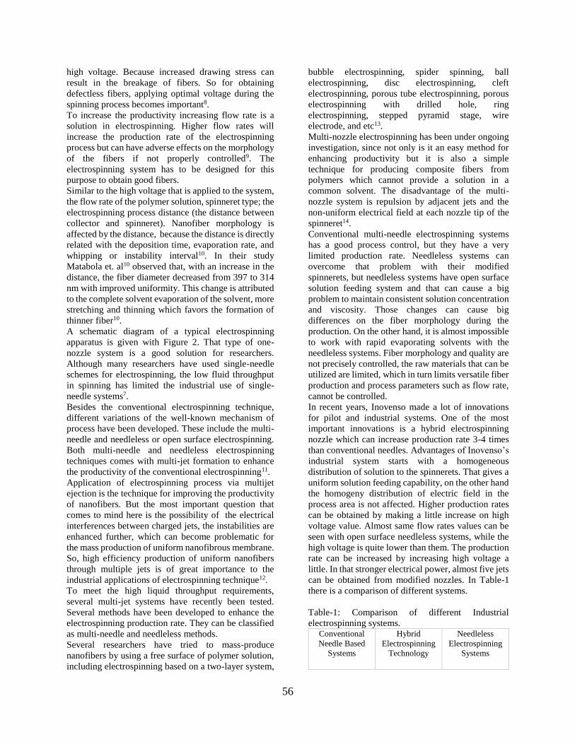
56
high voltage. Because increased drawing stress can
result in the breakage of fibers. So for obtaining
defectless fibers, applying optimal voltage during the
spinning process becomes important8.
To increase the productivity increasing flow rate is a
solution in electrospinning. Higher flow rates will
increase the production rate of the electrospinning
process but can have adverse effects on the morphology
of the fibers if not properly controlled9. The
electrospinning system has to be designed for this
purpose to obtain good fibers.
Similar to the high voltage that is applied to the system,
the flow rate of the polymer solution, spinneret type; the
electrospinning process distance (the distance between
collector and spinneret). Nanofiber morphology is
affected by the distance, because the distance is directly
related with the deposition time, evaporation rate, and
whipping or instability interval10. In their study
Matabola et. al10 observed that, with an increase in the
distance, the fiber diameter decreased from 397 to 314
nm with improved uniformity. This change is attributed
to the complete solvent evaporation of the solvent, more
stretching and thinning which favors the formation of
thinner fiber10.
A schematic diagram of a typical electrospinning
apparatus is given with Figure 2. That type of one-
nozzle system is a good solution for researchers.
Although many researchers have used single-needle
schemes for electrospinning, the low fluid throughput
in spinning has limited the industrial use of single-
needle systems7.
Besides the conventional electrospinning technique,
different variations of the well-known mechanism of
process have been developed. These include the multi-
needle and needleless or open surface electrospinning.
Both multi-needle and needleless electrospinning
techniques comes with multi-jet formation to enhance
the productivity of the conventional electrospinning11.
Application of electrospinning process via multijet
ejection is the technique for improving the productivity
of nanofibers. But the most important question that
comes to mind here is the possibility of the electrical
interferences between charged jets, the instabilities are
enhanced further, which can become problematic for
the mass production of uniform nanofibrous membrane.
So, high efficiency production of uniform nanofibers
through multiple jets is of great importance to the
industrial applications of electrospinning technique12.
To meet the high liquid throughput requirements,
several multi-jet systems have recently been tested.
Several methods have been developed to enhance the
electrospinning production rate. They can be classified
as multi-needle and needleless methods.
Several researchers have tried to mass-produce
nanofibers by using a free surface of polymer solution,
including electrospinning based on a two-layer system,
bubble electrospinning, spider spinning, ball
electrospinning, disc electrospinning, cleft
electrospinning, porous tube electrospinning, porous
electrospinning with drilled hole, ring
electrospinning, stepped pyramid stage, wire
electrode, and etc13.
Multi-nozzle electrospinning has been under ongoing
investigation, since not only is it an easy method for
enhancing productivity but it is also a simple
technique for producing composite fibers from
polymers which cannot provide a solution in a
common solvent. The disadvantage of the multi-
nozzle system is repulsion by adjacent jets and the
non-uniform electrical field at each nozzle tip of the
spinneret14.
Conventional multi-needle electrospinning systems
has a good process control, but they have a very
limited production rate. Needleless systems can
overcome that problem with their modified
spinnerets, but needleless systems have open surface
solution feeding system and that can cause a big
problem to maintain consistent solution concentration
and viscosity. Those changes can cause big
differences on the fiber morphology during the
production. On the other hand, it is almost impossible
to work with rapid evaporating solvents with the
needleless systems. Fiber morphology and quality are
not precisely controlled, the raw materials that can be
utilized are limited, which in turn limits versatile fiber
production and process parameters such as flow rate,
cannot be controlled.
In recent years, Inovenso made a lot of innovations
for pilot and industrial systems. One of the most
important innovations is a hybrid electrospinning
nozzle which can increase production rate 3-4 times
than conventional needles. Advantages of Inovenso’s
industrial system starts with a homogeneous
distribution of solution to the spinnerets. That gives a
uniform solution feeding capability, on the other hand
the homogeny distribution of electric field in the
process area is not affected. Higher production rates
can be obtained by making a little increase on high
voltage value. Almost same flow rates values can be
seen with open surface needleless systems, while the
high voltage is quite lower than them. The production
rate can be increased by increasing high voltage a
little. In that stronger electrical power, almost five jets
can be obtained from modified nozzles. In Table-1
there is a comparison of different systems.
Table-1: Comparison of different Industrial
electrospinning systems. Conventional
Needle Based
Systems
Hybrid
Electrospinning
Technology
Needleless
Electrospinning
Systems
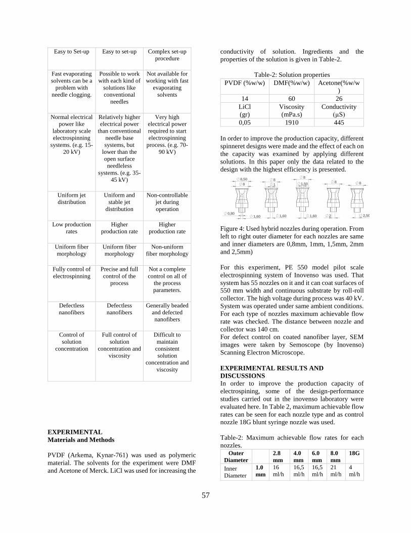
57
Easy to Set-up Easy to set-up Complex set-up
procedure
Fast evaporating
solvents can be a
problem with
needle clogging.
Possible to work
with each kind of
solutions like
conventional
needles
Not available for
working with fast
evaporating
solvents
Normal electrical
power like
laboratory scale
electrospinning
systems. (e.g. 15-
20 kV)
Relatively higher
electrical power
than conventional
needle base
systems, but
lower than the
open surface
needleless
systems. (e.g. 35-
45 kV)
Very high
electrical power
required to start
electrospinning
process. (e.g. 70-
90 kV)
Uniform jet
distribution
Uniform and
stable jet
distribution
Non-controllable
jet during
operation
Low production
rates
Higher
production rate
Higher
production rate
Uniform fiber
morphology
Uniform fiber
morphology
Non-uniform
fiber morphology
Fully control of
electrospinning
Precise and full
control of the
process
Not a complete
control on all of
the process
parameters.
Defectless
nanofibers
Defectless
nanofibers
Generally beaded
and defected
nanofibers
Control of
solution
concentration
Full control of
solution
concentration and
viscosity
Difficult to
maintain
consistent
solution
concentration and
viscosity
EXPERIMENTAL
Materials and Methods
PVDF (Arkema, Kynar-761) was used as polymeric
material. The solvents for the experiment were DMF
and Acetone of Merck. LiCl was used for increasing the
conductivity of solution. Ingredients and the
properties of the solution is given in Table-2.
Table-2: Solution properties
PVDF (%w/w) DMF(%w/w) Acetone(%w/w
)
14 60 26
LiCl
(gr)
Viscosity
(mPa.s)
Conductivity
(µS)
0,05 1910 445
In order to improve the production capacity, different
spinneret designs were made and the effect of each on
the capacity was examined by applying different
solutions. In this paper only the data related to the
design with the highest efficiency is presented.
Figure 4: Used hybrid nozzles during operation. From
left to right outer diameter for each nozzles are same
and inner diameters are 0,8mm, 1mm, 1,5mm, 2mm
and 2,5mm)
For this experiment, PE 550 model pilot scale
electrospinning system of Inovenso was used. That
system has 55 nozzles on it and it can coat surfaces of
550 mm width and continuous substrate by roll-roll
collector. The high voltage during process was 40 kV.
System was operated under same ambient conditions.
For each type of nozzles maximum achievable flow
rate was checked. The distance between nozzle and
collector was 140 cm.
For defect control on coated nanofiber layer, SEM
images were taken by Semoscope (by Inovenso)
Scanning Electron Microscope.
EXPERIMENTAL RESULTS AND
DISCUSSIONS
In order to improve the production capacity of
electrospining, some of the design-performance
studies carried out in the inovenso laboratory were
evaluated here. In Table 2, maximum achievable flow
rates can be seen for each nozzle type and as control
nozzle 18G blunt syringe nozzle was used.
Table-2: Maximum achievable flow rates for each
nozzles. Outer
Diameter
2.8
mm
4.0
mm
6.0
mm
8.0
mm
18G
Inner
Diameter
1.0
mm
16
ml/h
16,5
ml/h
16,5
ml/h
21
ml/h
4
ml/h
SCALE
DECEMBER 2018
4
0,80
2,80
8
1,72
3
11,8
6
3,30
1
2,80
1,72
1,50
1,72
2,80
2
2,80
2,50
2,80
4 4,50
1,72
0,80
4 1
1,72 1,72
1,50
4
2
4
2,50
4
1,72
6
6,50
0,80 1,72
1
6 6
1,50
1,72 2
6
2,50
6
8
8,50
1,60 0,80
1,60
8
1 1,50
8
1,60 2
8
2,50
8
2:1
DATE
A A
1
1
İNOVENSO NOZZLE

58
1.5
mm
16,5
ml/h
16,5
ml/h
17
ml/h
21,5
ml/h
2.0
mm
16,5
ml/h
17
ml/h
17
ml/h
24
ml/h
2.5
mm
17
ml/h
17,5
ml/h
28,5
ml/h
The most efficient design can be seen at Fig-5.
Achieved flow rate value for this nozzle is 28,5 ml/h.
Figure 5: Hybrid electrospinning spinneret.
SEM images for all of the nozzles on this experiment
were taken. But here only for the nozzle which gave the
highest performance is given. SEM images are given
with Fig-6
Figure 6: SEM image and fiber diameter distribution for
the nozzle which has OD:8mm and ID:2,5mm
For making comparison SEM image for standard
syringe needle is given at Figure-7. In this image it can
be clearly seen that nanofiber layer has defects.
Figure 7: SEM image for 18G blunt standard syringe
needle
CONCLUSIONS
In this study, the effect of various nozzle designs,
which were developed to increase nanofiber
production speed, on the effect of feed flow was
investigated. When the inner and outer diameters of
the hybrid nozzles were examined, the highest yield
was obtained with nozzle which has an ID of 2.5mm
and an OD of 8mm.
The morphology of the nanofiber coating produced
was examined by SEM and no serious defect affecting
the coating quality was observed.
Figure: Electrospinning process area of PE300.
ACKNOWLEDGEMENTS/SOURCES OF
FUNDING
This project is funded by Inovenso Teknoloji Ltd. All
the production and analysis were done at Inovenso’s
facility.
LITERATURE
020406080
100
42
0-4
40
44
0-4
60
46
0-4
80
48
0-5
00
50
0-5
20
52
0-5
40
54
0-5
60
56
0-5
80
Fre
qu
en
cy
Fiber Diameter (nm)

59
1. Akpınar, H. S. N. Production Of Electrospun
Polyacrylonitrile Nanofiber Yarn. (Technical
University Of Istanbul, 2018).
2. Merritt, S. R., Exner, A. A., Lee, Z. & von Recum,
H. A. Electrospinning and Imaging. Adv. Eng. Mater.
14, B266–B278 (2012).
3. Norton, C. L. Method Of And Apparatus For
Producing Fibrous Or Filamentary Material. 1–4
(1933).
4. Taylor, G. Electrically Driven Jets. Proc. R. Soc.
London 313, 453–475 (2014).
5. Collins, G., Federici, J., Imura, Y. & Catalani, L. H.
Charge generation, charge transport, and residual
charge in the electrospinning of polymers: A review of
issues and complications. J. Appl. Phys. 111, (2012).
6. Casasola, R. Electrospinning of poly (lactic) acid for
biomedical applications: analysis of solution properties
and process parameters, drug encapsulation and release.
(2016).
7. Angammana, C. J. & Jayaram, S. H. Fundamentals
of electrospinning and processing technologies. Part.
Sci. Technol. 34, 72–82 (2016).
8. Mishra, R. K. et al. Electrospinning production
of nanofibrous membranes. Environmental Chemistry
Letters (Springer International Publishing, 2018).
doi:10.1007/s10311-018-00838-w
9. SalehHudin, H. S., Mohamad, E. N., Mahadi, W. N.
L. & Muhammad Afifi, A. Multiple-jet electrospinning
methods for nanofiber processing: A review. Mater.
Manuf. Process. 33, 479–498 (2018).
10. Matabola, K. P. & Moutloali, R. M. The influence
of electrospinning parameters on the morphology and
diameter of poly(vinyledene fluoride) nanofibers-
Effect of sodium chloride. J. Mater. Sci. 48, 5475–5482
(2013).
11. Kenry & Lim, C. T. Nanofiber technology: current
status and emerging developments. Prog. Polym. Sci.
70, 1–17 (2017).
12. Zheng, G. et al. Multinozzle high efficiency
electrospinning with the constraint of sheath gas. J.
Appl. Polym. Sci. 136, 1–12 (2019).
13. Valipouri, A. Production Scale Up of Nanofibers :
A Review. J. Text. Polym. 5, 8–16 (2017).
14. Park, C. H., Pant, H. R. & Kim, C. S. Novel robot-
assisted angled multi-nozzle electrospinning set-up:
Computer simulation with experimental observation
of electric field and fiber morphology. Text. Res. J.
84, 1044–1058 (2014
60
Development of Self-healing EVA Films SEZER HİÇYILMAZ, Ayşe1, ÇELİK BEDELOĞLU, Ayşe 1
1Bursa Technical University, Fiber and Polymer Engineering, Bursa, TURKEY
[email protected], [email protected]
PURPOSE
In recent years, self-healing materials have attracted
attention due to rapid recovery and wide application
area. The aim of this study was to provide self-healing
properties of ethylene vinyl acetate (EVA) films and to
characterize the properties of newly developed films.
INTRODUCTION
Self-healing materials heal themselves autonomically
or non-autonomicaly by help of external interventions
such as heat, light, oxygen or healing agents 1. Self-
healing materials are environmentally friendly,
sustainable, cost-effective due to their long service life
and the fact that they do not require replacement. More
importantly, self-healing materials give users more
secure handling because they can be repaired
autonomously, easily and quickly compared to
traditional materials 2. Therefore, in this study, EVA
polymer, which is used in a wide range of applications
from flexible packages to electrical cables, has been
chosen as the main material. 3. Nanoparticles are special
materials that have superior properties such as electrical
conductivity, thermal conductivity, antibacterial, super
hydrophobicity etc. 4. Moreover, it is possible to obtain
self-healing materials with nanoparticles. Silver
nanowires have high thermal conductivity and
photothermal property so they are suitable to produce
self-healing materials with polymers that have low
melting temperature. Healing mechanism of this
nanocomposites based on re-entanglement of linear
chains by softening or melting with heating of the
damaged region. In the literature, Li et al. produced the
near-infrared light induced healable, electrically
conductive, flexible silver nanowires (AgNWs)
deposited thermoplastic polycaprolactone
(PCL)/poly(vinyl alcohol) (PVA) composite film.
Recyclable healing is obtained by irradiating mild NIR
light the damaged region. AgNWs act as electricity
conductor and NIR light-induced heater. AgNW
absorbs NIR light and converts into heat then transfer
to the matrix. When the heated (PCL/PVA)6 film
reached to above of the melting temperature (65 °C),
polymer flows to heal the cutted
region and recover the electrical conductivity
property (Figure 12) 5. Kim et al fabricated
photoinduced self-healing, stretchable and
transparent TPU electrode with incorporating of
AgNW. Damaged surface was irradiated by intense-
pulsed-light (IPL) to induce plasmonic heating. Rapid
and repeatedly healing of the microcracks was
achieved by the help of thermally conductive AgNW 6. In this study, silver nano wire (AgNw) reinforced
ethylene vinil acetate (EVA) nanocomposites were
produced to obtain thermally self-healing property.
Generally in the literature silver nanowires were
coated onto polymer surface, in this study, rapid,
repeatable and high effective self-healing films were
produced by dispersing AgNw in the polymer matrix.
Developed self-healing nanocomposite transparent
films could be used in applications such as flexible
packaging, tempered glass laminates, electric cables,
footwear etc.
EXPERIMENTAL
Material
Greenflex ® Ethylene vinyl acetate copolymer (EVA)
was purchased from Resinex, ClearOhm® Ink- Silver
nanowire (AgNw) solution was purchased from
Cambrios and used as is. Dichlorobenzene was
purchased from Sigma Aldrich Chemical Company.
Method
EVA -DCB solution (10% wt/wt) was prepared at 130
°C. To prepare EVA-AgNw solution (5 % wt/wt), Ag
Nw was dispersed in DCB for 3 hours, then
ultrasonicated for 5 seconds. AgNw-DCB dispersion
was added into EVA-DCB solution at 130 °C. The
films were produced with solution casting method.
Hot polymer solutions poured onto glass petri dishes
that stands on 130 °C hot plates. The solvent
evaporated and the films cooled down gradually. The
films were named as EVA and AgNw-EVA. The
thicknesses of films were between 0.15-0.25 mm.
Self-healing property evaluated with scratch test
method 7. Films were scratched with a razor blade to
an approximately 50% thickness of the films and
heated in the 130 °C oven (Figure 1). Heating
temperature and time effect on the self-healing
property were investigated.
61
Figure 1. Scratched EVA films in petri dish.
Self-healing effect was observed with a light optical
microscope (Leica DM2500) and also mechanical
strength of the films tested according to ASTM D882
standard with A Shimadzu AGS X–Static Mechanical
Tester.
EXPERIMENTAL RESULTS AND
DISCUSSIONS
Self-healing tests were done at 90, 100, 110, 120 ve 130
°C for 1, 2.5, 5, 7.5 10, 15 minutes. Self-healing
behavior of the films were observed with optical
microscope. According to the results, AgNw-EVA
films at 90, 100 and 110 °C recovered for long periods
of time such as 1 hour, 35 minutes, 20 minutes,
respectively. Therefore these temperatures indicate that
it is not sufficient for rapid recovery. AgNw–EVA films
recovered at 120 °C after 10 minutes, while the non-
reinforced EVA film recovered after 15 minutes. The
fastest self-healing took place at 130 °C, the AgNw-
EVA film recovered after 5 minutes, while the EVA
film did not recover after 5 minutes (Figure 2). These
results indicated that %5 AgNw reinforcement increase
the self-healing effect of EVA film obviously and also
self-healing time decreased at least 66,66%. Silver
nanowires increase the healing time by increasing
thermal conductivity of the films.
Figure 2. Optical microscope images of EVA and
AgNw films before and after self-healing test at 130 °C
Mechanical strengths of the films were investigated
and test results were shown in Table 1. Mechanical
test results confirm optical microscope results. Silver
nanowire reinforcement decreased the mechanical
strength of the EVA films slightly. But after the self-
healing test (5 minutes), the AGNw-Eva film is
completely healed and achieves higher tensile stress
compared to pristine AgNw-EVA film due to re-
entanglement of the EVA chains with heat.
Table 1. Tensile test results of pristine and healed (at
130 °C) EVA and AgNw-EVA films.
Sample Tensile Stress
(N/mm2)
EVA 17,34
EVA-5 min 16,52
EVA-10 min 17,36
AgNw-EVA 16,73
AgNw-EVA-5 min 17,41
AgNw-EVA-10 min 17,14
CONCLUSIONS
Rapid self-healable EVA films were developed with
low amount of AgNw reinforcement (5%). Developed
films protect transparent structure and also
mechanical strength. These films could be used in
wide range of applications such as electric cables,
packages, coatings etc. Also it can be used as
tampered glass laminates due to high transparency
SUGGESTION FOR FURTHER WORK
Scratch formation process need to be optimized via
scratch maker devices. Silver nanowire dispersion
could be increased by using surfactant materials. On
the other hand, different reinforcement amounts and
also film thickness effects will be investigated in the
future works. Local self-healing tests will be
conducted in the next works.
REFERENCES
1 Thakur VK, Kessler MR, 2015.''Self-
healing polymer nanocomposite materials: A
review''. Polymer, (69),369-83.
2 Bekas D, Tsirka K, Baltzis D, Paipetis
A, 2016.''Self-healing materials: a review of
advances in materials, evaluation,
characterization and monitoring techniques''.
Composites Part B: Engineering, (87),92-119.
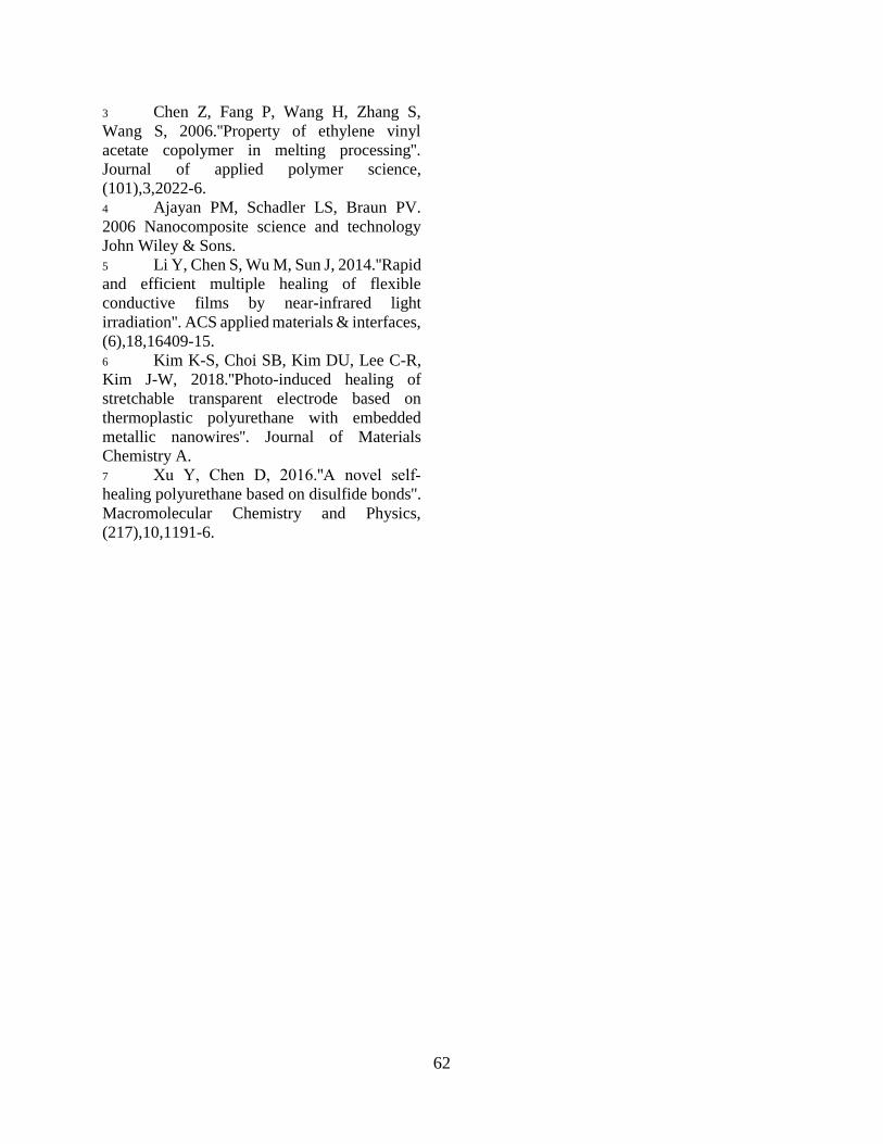
62
3 Chen Z, Fang P, Wang H, Zhang S,
Wang S, 2006.''Property of ethylene vinyl
acetate copolymer in melting processing''.
Journal of applied polymer science,
(101),3,2022-6.
4 Ajayan PM, Schadler LS, Braun PV.
2006 Nanocomposite science and technology
John Wiley & Sons.
5 Li Y, Chen S, Wu M, Sun J, 2014.''Rapid
and efficient multiple healing of flexible
conductive films by near-infrared light
irradiation''. ACS applied materials & interfaces,
(6),18,16409-15.
6 Kim K-S, Choi SB, Kim DU, Lee C-R,
Kim J-W, 2018.''Photo-induced healing of
stretchable transparent electrode based on
thermoplastic polyurethane with embedded
metallic nanowires''. Journal of Materials
Chemistry A.
7 Xu Y, Chen D, 2016.''A novel self‐
healing polyurethane based on disulfide bonds''.
Macromolecular Chemistry and Physics,
(217),10,1191-6.

63
Potential of Ethiopian Enset Fiber for Textile Application
TEMESGEN, Alhayat G. 1*, TURŞUCULAR, Ömer F.1*, EREN, Recep 1, AYKUT, Yakup 1
1Department of Textile Engineering, Engineering Faculty, Bursa Uludag University, Bursa, Turkey
Corresponding author:* [email protected], [email protected]
PURPOSE OF THE STUDY
Growing of environmental issue, increasing demand
of new materials, the evolution of new technology and
economic concerns as well as the finite petrochemical
resources have pushed researcher to find out
alternative materials to substitute synthetic fibers.
Enset plant was one of the most known drought
tolerance than most cereal crops, grows in every
season and multipurpose plant in Africa especially, in
Ethiopia, which is used as source of food in
southwestern part of the country. Enset fiber was
obtained from the agricultural waste of Enset plant
after extraction of edible part the so called “Kocho”.
The fundamental problem of farmers were disposal of
agro-waste material like enset fiber. Utilization of
agro-waste materials were generate additional income
for the low income farmer and poverty alleviation
program. The fibers, sometimes called false banana
under Ensete Ventricosum family, were new and un-
utilized agro waste obtained from the pseudo stem
(bast) and mid ribs of the plant. Enset fiber had
relatively low density, low moisture content and good
specific strength than from most common bast and leaf
fibers. Its abundantly available, low cost, reduced
energy consumption, carbon dioxide sequesterization,
and biodegradability were the merits of the fiber from
other most natural fiber used in reinforced green
composite and technical textiles like Geo textile and
Agro textile areas.
Key words: Enset Fibers, Extraction, Composite,
Physical properties, Textile Potential.
1. INTRODUCTION
Textile production has been developing to increase
efficiency to serve consumer’s needs. As the
convenience increases, villagers tend to neglect
traditional fiber harvesting process and turn to
synthetic fibers and chemicals to achieve production
capability, including expensive imported fibers and
yarns purchased from foreign traders, whereas the
local cheap material available in their hometown is
ignored [1, 2 and 3]. Interest in using natural fibers has
increased significantly in the last few years, especially
because of their use as an agent of reinforcement and
more recently as heavy metals bio-adsorbent [1,4]
Enset plant is in Musa family like banana. The plant is
a large perennial herb with leaf sheaths that form
pseudo stem. Its height can be 3.0-12.2 meters
surrounding with 8-12 large leaves. The leaves are up
to 9 feet long and 2 feet wide (2.7 meters and 0.61
meter). Its fruits are approximately 4-12 inches (10.2-
30.5 centimeters) [3, 5, 6, 7, 8]. Different parts of
banana trees serve different needs, including fruits as
food sources called ”KOCHA”, leaves as wrapping,
and stems for fiber and robe. The fiber is obtained
from outer layers from the stalks of the plant. It is light,
strong and durable. After extraction and dry, it
provides a white lustrous color fiber (figure 1). One
particular characteristic of the fiber over all other
fibers of its class is the great strength and resistance to
the action of water, therefore its will be particular
adaptability for marine ropes [9]. It is available in
some part of Africa (Figure 2).
According to environmental concerns in European
countries, recently, natural fibers play an important
role as reinforcing fillers in polymer composites. The
advantages of natural fibers over synthetic fibers are
their low cost, less tool wear during the process, low
density, environmental friendliness and
biodegradability [1,3,10]. For that reason, enset fibers
will be another option to be investigated for its fiber
source potential.
Figure 1: Enset fiber
Generally there are the six major kinds of Ensete in the
Musa family[5,11].

64
Figure 2. Ensete in Africa (source: Alun Salt, 2019)
Fibers have an average equivalent diameter of 194-206
µm and a length of 0.5 to 4.5 m. These long technical
fibers are generally characterized by hard, stiff and
coarse in texture. Different type of enset fibers are
collected from different region of Ethiopia and
mechanical and physical properties of the fibers will
be characterizations done [1, 2, 3, 12-15]. In addition
to this, we are try to compare and contrast with the
overall properties if the fiber with banana fiber. Finally
we will try to find out the possible enset fiber
extraction techniques to optimize the fiber strengths
[1, 2, 3, 12.13].
The significances of this study was using left-over
banana trunk as raw material in environmental-
friendly manner to optimize natural fiber processes
and decrease chemical and toxic agents in the process.
As the material is available locally, villagers are not
necessary to purchase or grow new plant and using
extra chemicals, fertilizers, or pesticides. Utilizing
enset fibers will promote sustainable development in
the community, since villagers will be able to produce
this fiber in their household. This research focused on
the amount of fiber extraction, the comparison of fiber
extraction methods, characterization of the fiber and
investigation of the potential application in technical
textile. The findings from this research presented that
the yield test of is acceptable for light weight
composite production. The result expresses the
possibility for more exploration in industrial area,
which should include the whole process of fully
utilizing enset plant after harvesting the food “Kocho”,
enset fiber and enset pulp.
2. MATERIALS AND METHODS
Fibers were collected and extracted from different
part of Ethiopia from mid ribs and pseudo stem of the
enset plants and studied. Fibers were continuously
scratched by hand followed by washing, cleaning and
manual fiber separation. Microscopic view of the fiber
was seen by using SEM with 150x magnification
power. FTIR test was analyzed with measuring range:
4000 - 650cm-1, number of scans: 32 and resolution:
4cm-1. Tests have been conducted under standard
conditions: ISO 139 20°C 2°C and 65% 4% R.H
in BUTAL and Bursa Uludag University laboratory,
Bursa Turkey.
3. RESULTS AND DISCUSSIONS
3.1. Enset Fibers Extraction
Enset fibers are extracted from the pseudo stem and
mid ribs of the plant. The extraction of starch and fiber
from the plant mostly takes place by using either
mechanically by hand or by using decortication
machine. The pseudo stem are cut in to the required
size and tied with a fixed wood at certain inclination
and separate the starch from the fiber. The qualities of
the fibers are depending on the setting between the
lower and upper cylinder of decortication machine.
Sometimes fiber can also extracted from the plant by
soaking with water and caustic soda for a certain
period of time. These kinds of fiber extraction
mechanisms mostly affect the overall mechanical
performance of the fiber. Because the microorganism
may start to grow and eat the cellulose part of the
fibers see figure 3 a
Figure 3. (a) Raw enset fiber (b) Clean enset fiber
3.2. FTIR Analysis of Enset Fiber
The FTIR result of the enset fiber consists for 3331
absorption O-H stretching ,2917 absorption C-H
stretching (aliphatic + aromatic) ,1100 absorption
band C-O stretching of conjugated ester groups in
grass lignin’s and 1242 absorption C=C stretch were
observed. FTIR adsorption band indicated that enset
fiber has three major chemical compositions:
cellulose, hemicellulose and lignin. Like other
lignocellulose fibers, the physical and mechanical
performance of the fiber as well as the bio composite
materials reinforced with enset fibers were
significantly affected by three major constituents,

65
especially the percentage of hemicellulose and lignin
present in the enset fiber.
Table 1. FTIR absorption of Enset fiber in BUTAL.
Figure 4: IR Spectra of Enset fiber
3.3. Morphological Properties of Enset fiber
Enset fibers had a hard touch and core fiber like other
most bast fiber. We can also observe longitudinal
streaks which are characteristics of long vegetable
fibers and same starch material which were not
removed from the fiber during fiber extraction (figure
5a). Moreover, in a single fiber of enset contains a lot
of hole and cross sectional area having a shape of bean,
which indicate that in a single enset fiber, there is a
possibility to extract a lot of fine fiber (figure 5b)
By examining these technical fibers in SEM (Scanning
Electron Microscope) we can see a ″composite″
structure where ultimate fibers are held together by
sticky and waxy substances to finally form technical
fiber with section forms difficult to define. The
ultimate fibers show oval and irregular sections with
large lumen (figure 5c).
Figure 5: SEM view of Enset fiber (a) Longitudinal
View (b) Cross sectional view (c) Number of layers of
in a single fiber (natural composite fiber)
From figure 5b and 5c, enset fiber have a lot of whole
structure both in the longitudinal as well as transversal
direction of the fiber axis. Theses open spaces present
on the fiber structure have a significant advantage in
the acoustic application and absorbed desired amount
of matrix in green composite. Comparison with other
textile fibers, fibers are more hydrophilic than cotton,
flax, and other lignocellulose vegetable fibers with
moisture content of 7- 10%.
CONCLUSION
Their abundance in nature combined with the ease of
their processing had an attractive feature, which makes
enset fiber an important substitute for synthetic fibers.
The test results indicated that , Enset pseudo-stem
suggest that this material which is residue after
harvesting Kocha can be used as potential source of
cellulose fiber to make high valued ecofriendly
technical materials like biodegradable composite, geo-
textile, agro-textile and packaging mats which gives
high strength without any finishing. The agro waste
naturally composite fibers were ecofriendly,
economically fit as well as disposable material and
play a significant role in reduction of carbon
emissions. The farmers in Ethiopia are cultivated the
plant for food source, but after extraction of the
required food the disposal of this agro waste fiber was
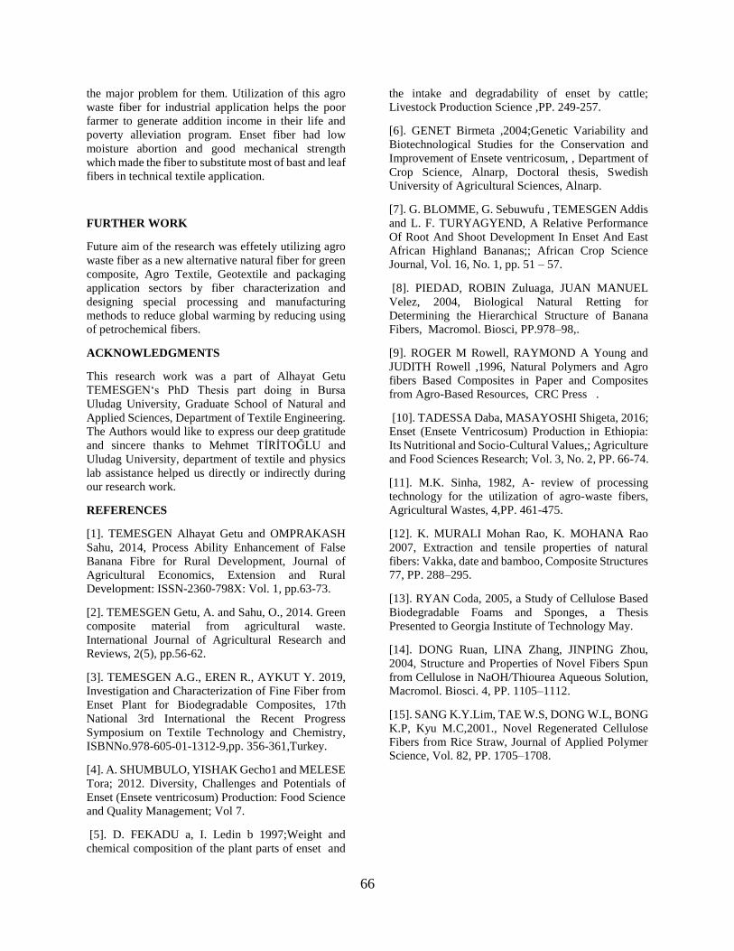
66
the major problem for them. Utilization of this agro
waste fiber for industrial application helps the poor
farmer to generate addition income in their life and
poverty alleviation program. Enset fiber had low
moisture abortion and good mechanical strength
which made the fiber to substitute most of bast and leaf
fibers in technical textile application.
FURTHER WORK
Future aim of the research was effetely utilizing agro
waste fiber as a new alternative natural fiber for green
composite, Agro Textile, Geotextile and packaging
application sectors by fiber characterization and
designing special processing and manufacturing
methods to reduce global warming by reducing using
of petrochemical fibers.
ACKNOWLEDGMENTS
This research work was a part of Alhayat Getu
TEMESGEN‘s PhD Thesis part doing in Bursa
Uludag University, Graduate School of Natural and
Applied Sciences, Department of Textile Engineering.
The Authors would like to express our deep gratitude
and sincere thanks to Mehmet TİRİTOĞLU and
Uludag University, department of textile and physics
lab assistance helped us directly or indirectly during
our research work.
REFERENCES
[1]. TEMESGEN Alhayat Getu and OMPRAKASH
Sahu, 2014, Process Ability Enhancement of False
Banana Fibre for Rural Development, Journal of
Agricultural Economics, Extension and Rural
Development: ISSN-2360-798X: Vol. 1, pp.63-73.
[2]. TEMESGEN Getu, A. and Sahu, O., 2014. Green
composite material from agricultural waste.
International Journal of Agricultural Research and
Reviews, 2(5), pp.56-62.
[3]. TEMESGEN A.G., EREN R., AYKUT Y. 2019, Investigation and Characterization of Fine Fiber from
Enset Plant for Biodegradable Composites, 17th
National 3rd International the Recent Progress
Symposium on Textile Technology and Chemistry,
ISBNNo.978-605-01-1312-9,pp. 356-361,Turkey.
[4]. A. SHUMBULO, YISHAK Gecho1 and MELESE
Tora; 2012. Diversity, Challenges and Potentials of
Enset (Ensete ventricosum) Production: Food Science
and Quality Management; Vol 7.
[5]. D. FEKADU a, I. Ledin b 1997;Weight and
chemical composition of the plant parts of enset and
the intake and degradability of enset by cattle;
Livestock Production Science ,PP. 249-257.
[6]. GENET Birmeta ,2004;Genetic Variability and
Biotechnological Studies for the Conservation and
Improvement of Ensete ventricosum, , Department of
Crop Science, Alnarp, Doctoral thesis, Swedish
University of Agricultural Sciences, Alnarp.
[7]. G. BLOMME, G. Sebuwufu , TEMESGEN Addis
and L. F. TURYAGYEND, A Relative Performance
Of Root And Shoot Development In Enset And East
African Highland Bananas;; African Crop Science
Journal, Vol. 16, No. 1, pp. 51 – 57.
[8]. PIEDAD, ROBIN Zuluaga, JUAN MANUEL
Velez, 2004, Biological Natural Retting for
Determining the Hierarchical Structure of Banana
Fibers, Macromol. Biosci, PP.978–98,.
[9]. ROGER M Rowell, RAYMOND A Young and
JUDITH Rowell ,1996, Natural Polymers and Agro
fibers Based Composites in Paper and Composites
from Agro-Based Resources, CRC Press .
[10]. TADESSA Daba, MASAYOSHI Shigeta, 2016;
Enset (Ensete Ventricosum) Production in Ethiopia:
Its Nutritional and Socio-Cultural Values,; Agriculture
and Food Sciences Research; Vol. 3, No. 2, PP. 66-74.
[11]. M.K. Sinha, 1982, A- review of processing
technology for the utilization of agro-waste fibers,
Agricultural Wastes, 4,PP. 461-475.
[12]. K. MURALI Mohan Rao, K. MOHANA Rao
2007, Extraction and tensile properties of natural
fibers: Vakka, date and bamboo, Composite Structures
77, PP. 288–295.
[13]. RYAN Coda, 2005, a Study of Cellulose Based
Biodegradable Foams and Sponges, a Thesis
Presented to Georgia Institute of Technology May.
[14]. DONG Ruan, LINA Zhang, JINPING Zhou,
2004, Structure and Properties of Novel Fibers Spun
from Cellulose in NaOH/Thiourea Aqueous Solution,
Macromol. Biosci. 4, PP. 1105–1112.
[15]. SANG K.Y.Lim, TAE W.S, DONG W.L, BONG
K.P, Kyu M.C,2001., Novel Regenerated Cellulose
Fibers from Rice Straw, Journal of Applied Polymer
Science, Vol. 82, PP. 1705–1708.

67
Thermal Insulation Properties of Glass Fiber Epoxy
Composite with Stonewool Fiber, Nanofiber Web,
Silica Aerogel Layers GÜNAL, Sevde Rana1, SAYAR, Ersin2, GEYGEL, Berkay3, ÖZKAN
HACIOĞULLARI, Selcen4, KARACA, Neslihan5, UÇAR, Mehmet3, SELVER,
Erdem6, SOLAK, Nuri1, BAYDOĞAN, Murat1, ÖNEN, Ayşen5, UÇAR, Nuray4
1İTÜ, Malzeme Müh Böl, Maslak, İstanbul, TÜRKİYE 2İTÜ, Makine Müh Bölümü, Gümüşsuyu, Taksim, İstanbul TÜRKİYE
3Kocaeli Üniversitesi, Otomotiv Müh Bölümü, İzmit, TÜRKİYE 4İTÜ, Tekstil Müh Böl, TESENLİF Laboratuvarı, Gümüşsuyu, Taksim,
5İTÜ, Kimya Bölümü, Maslak, İstanbul, TÜRKİYE 6Kahramanmaraş Sütçü İmam Üniversitesi, Tekstil Müh Böl, Kahramanmaraş
ABSTRACT
Thermal insulation is very important for transportation
industry including aircraft, train, automobile, etc. Glass
fiber epoxy composite with nonwoven containing
Polyacrylonitrile nanofiber, silica aerogel, stone wool
fiber layers have been evaluated for thermal insulation.
INTRODUCTION
Glass fiber epoxy composite is widely used in
transportation industry including aircraft, train,
automobile, ship, etc. and other areas such as cryogenic.
Heat insulation is very important for these areas. Silica
aerogels with its nano porous structure and mass, is a
very suitable material to be used as super insulating
composite material1. Polyacrylonitrile (PAN) is a
versatile man-made polymer and has been used in a
large array of products. Also, this polymer has the good
thermal properties.2
Stone wool is a fire-resistant, water-repellent heat and
sound insulation material containing 97% natural fibers
and produced by melting minerals and inorganic stones
derived from volcanic rocks such as basalt, diabase and
dolomite between 1400-1500 °C to form fibers3. It is
used for thermal insulation, sound insulation, acoustic
comfort as well as fire safety. In this study, glass fiber
epoxy composite structures with insulating properties
were developed using these materials. The morphology
and thermal insulation have been analyzed. It has been
seen that nanofiber, silica aerogel and stone wool
blanket used for insulation material result to decrease of
heat transfer coefficient due to pores in the structures,
compared to reference glass fiber epoxy composite
without any insulation layer.
EXPERIMENTAL
Material
Glass fabric ( 525 g/m2 , plain weave , 2 weft/cm, 2
warp/cm, 0.4 mm thickness), Epoxy (F-1564), curing
agent (F-3486) purchased from Fibermak.
Commercial available silica aerogel ENOVA® MT
1200 (Cabot´s Aerogel), nonwoven fabric (spunlace),
Polyacrylonitrile, stonewool have been used.
Method
PAN/DMF (%8 PAN) have been used for
electrospinning system with set up 14 kV voltage, 14
cm distance, 0,9 ml/h feeding rate and 21 needle
gauge. Nanofiber web has been electrospun on
nonwoven layer. The thickness of PAN nanofiber web
and also each nonwoven layer are approximately
0.085 mm. Silica aerogel particle (0,25 gr) has been
placed on nonwoven layer.
Heat flow meter (by using steady heated insulated
plate, laboratory type/handmade measurement
device) was used to measure heat transfer coefficient.
Glass fiber epoxy composite (ratio of 62/38 %) has
been produced by hand laying technique using brush
for the 0-0 placement with 6 glass woven fabric.
Each of insulation materials have been layered on
glass fiber epoxy composite as given in Table 1.

68
Table-1. Materials used in this study
No
Material/
Sample
Design
Layers type
Thickness
(mm)/
Weight
(gr/m2)
1
Reference
Glass Fiber
Epoxy
Composite
(RGC)
Glass Fiber
Epoxy
Composite
3 mm
4600 g/m2
2
Glass Fiber
Epoxy
Composite
with stone
wool fiber
blanket layer
with 2 mm
thickness
(GCSW)
Glass Fiber
Epoxy
Composite
+
Stone Wool
Fiber Blanket
Layer with
approx. 2 mm
Thickness
5 mm
5068 g/m2
3
Glass
Composite+
Silica Aerogel
layer with 2
mm thickness
(GCS)
Glass
Composite+
nonwoven (23
layers) and
Silica Aerogel
(2 layers)
(approx. 2 mm
thickness)
5,5 mm
4933 g/m2
4
Glass
Composite+
PAN
Nanofiber
(GCP)
Glass
Composite+
nonwoven
(21 layers)
and nonwoven
with PAN
layer
(4 layers)
( approx. 2
mm thickness)
5,5 mm
4978 g/m2
EXPERIMENTAL RESULTS
As can be seen from Figure 1, nanofiber is in nanometer
range and silica aerogel particle is in micron range. As
can be seen from Table 2, nanofiber with 2 layer, silica
aerogel with 2 layer and stone wool blanket used for
insulation material result to decrease of heat transfer
coefficient due to pores in the structures, compared to
reference glass fiber epoxy composite without any
insulation layer. Even though, heat transfer coefficient
of nonwoven with PAN nanofiber is some higher than
others, the easy production process and cost of
nanofiber may be preferable.
a b
c d
Figure 1. Morphology a-SEM appearance of PAN
nanofiber, b- SEM appearance of Silica Aerogel and
c-Stone wool blanket, d-glass fiber/epoxy composite
Table 2. Thermal insulation properties
No
Material/
Sample Design
Heat transfer
coefficient
W/mK
1
Reference Glass Fiber
Epoxy Composite (RGC) 0.140W/mK
2
Glass Fiber Epoxy
Composite with stone
wool fiber blanket layer
with approx. 2 mm
thickness (GCSW)
0.078W/mK
3
Glass Composite+
Silica Aerogel layer with
approx. 2 mm thickness
(GCS)
0.088W/mK
4
Glass Composite+
PAN Nanofiber (GCP)
with approx.2 mm
thickness
0.093W/mK
CONCLUSIONS
Nanofiber, silica aerogel and stone wool blanket used
for insulation material result to decrease of heat
transfer coefficient due to pores in the structures,

69
compared to reference glass fiber epoxy composite
without any insulation layer. Heat transfer coefficient
of nonwoven with PAN nanofiber is some higher than
others, however, the easy production process and cost
of nanofiber may be preferable.
ACKNOWLEDGMENT
This study has been supported by TUBITAK under the
project TÜBİTAK COST “218M766. We would like to
thank TUBITAK. We also would like to thank
producers/ distributors which provides some raw
materials.
REFERENCES
[1] Venkataraman, M., Mishra, R., Militky, J. and Hes,
L. 2014. “Aerogel Based Nanoporous Fibrous Materials
for Thermal Insulation”, Fibers and Polymers, Vol. 15,
1444-1449.
[2] Madakbas¸ S., Çakmakçı, E., Kahraman, M. V.
2013. “Preparation and thermal properties of
polyacrylonitrile/hexagonal boron nitride composites”,
Thermochimica Acta, 552, 1– 4.
[3]WEB:https://www.bonusyalitim.com.tr/en/products
/bonus-stone-wool

70
Investigation of Wear Properties of Polyethylene/Carbon
Fiber Composites AKGUL, Yasin1, AHLATCI, Hayrettin1, SIMSIR, Hamza2, TOPTAS, Ali3, ERDEN, Mehmet Akif4, KILIC, Ali3
1 Department of Metallurgical and Materials Engineering, Karabuk University, Karabuk, Turkey, 2 TOBB Technical Science Vocational School, Karabuk University, Karabuk, Turkey
3 TEMAG Labs, Textile Technology and Design Faculty, Istanbul Tech University, Istanbul, Turkey 4 Department of Biomedical Engineering, Karabuk University, 78050, Karabuk, Turkey
PURPOSE
The aim of this study is to improve the wear resistance
of linear low-density polyethylene (LLDPE) material.
For this purpose, LLDPE matrix composites containing
different amounts (1%, 2.5%, %5, 10%, 15%, 20%) of
carbon fiber are produced via twin-screw extrusion and
injection molding.
INTRODUCTION
Polyethylene (PE) is one of the most used materials for
tribology in biomedical applications due to its excellent
wear and chemical resistance (Liu et al. 2012).
Although it is currently the most frequently used
bearing surface, it does not fully provide the expected
tribological performance (Goodman and Lidgren 1992).
Therefore, in recent years, researchers have conducted
studies to improve the wear resistance of PE matrix
composites (Liu et al. 2014).
Lahiri et al. (Lahiri et al. 2014) investigated the
tribological behavior of graphene nanoplatelets
reinforced ultra-high molecular weight polyethylene
(UHMWPE) composites. Results show that the
coefficient of friction (COF) of UHMWPE decreased
by 68% with 1% graphene addition. In another study,
Akinci et al. (Akinci, Yilmaz, and Sen 2012) studied
wear behavior of basalt filled low-density polyethylene
(LDPE) composites. It was observed that
30%Basalt/70%LDPE composite has 90% less wear
rate compared to pure LDPE under 20 N load. Also, no
change in wear resistance was observed in the
reinforcement range from 30% to 70%. In another
similar study, Gogoleva et al. (Gogoleva et al. 2015)
examined the mechanical and tribological properties of
basalt fibers/UHMWPE composites. Wear resistance of
5% basalt fiber reinforced composites was nearly 7
times higher than pure UHMWPE. To sum up, the
tribological properties of PE can be increased with
different types of fillers.
Carbon fibers (CF) are promising fillers for polymer
matrix composites due to their light mass and superior
mechanical properties (Akgul et al. 2019). In this study,
the effect of content on wear properties PE matrix
composites was investigated. Also, the hardness test
was performed.
EXPERIMENTAL
Material
LLDPE granules with 17 MFI (ASPUN™ 6834) and
carbon fibers with a length of 3-6 mm were purchased
from DowAksa LLC., USA.
Method
Carbon fibers and LLDPE granules were mixed using
a twin-screw extrusion process. Then, composite
samples with dog bone shape were produced via
injection molding. Reciprocating wear test was
conducted for each sample using simulation body
fluid (SBF) under three different loads (20 N, 30 N,
50 N). Also, the Vickers hardness test was performed.
EXPERIMENTAL RESULTS AND
DISCUSSIONS
The hardness of the samples was presented in Figure
1. It can be seen that the hardness values of the
samples increased with the increase in carbon fiber
ratio. The hardness value of PE-20CF has two times
greater than pure LLDPE. This can be attributed that
polymer chain movement is restricted with the
addition of CF and presence of harder CF in the
composites (Akgul et al. 2019).
Figure 1. The hardness of composites and pure
LLDPE.
Figure 2 shows the wear rates of samples containing
carbon fiber up to 5% against different applied loads.
It can be observed that composite samples have better
wear resistance than pure LLDPE. This is because CF
has lubricant effect and stiffer than pure PE. PE-2.5
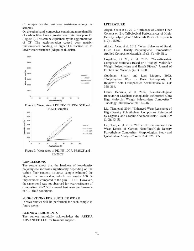
71
CF sample has the best wear resistance among the
samples.
On the other hand, composites containing more than 5%
of carbon fiber have a greater wear rate than pure PE
(Figure 3). This can be explained by the agglomeration
of CF. The agglomeration caused poor matrix-
reinforcement bonding, so higher CF fraction led to
lower wear resistance (Akgul et al. 2019).
Figure 2. Wear rates of PE, PE-1CF, PE-2.5CF and
PE-5CF samples.
Figure 3. Wear rates of PE, PE-10CF, PE15CF and
PE-20CF
CONCLUSIONS
The results show that the hardness of low-density
polyethylene increases significantly depending on the
carbon fiber content. PE-20CF sample exhibited the
highest hardness value, which has nearly 100 %
improvement compared to the pure LLDPE. However,
the same trend was not observed for wear resistance of
composites. PE-2.5CF showed best wear performance
in SBF fluid conditions.
SUGGESTIONS FOR FURTHER WORK
In vivo studies will be performed for each sample in
future works.
ACKNOWLEDGMENTS
The authors gratefully acknowledge the AREKA
ADVANCED LLC. for financial support.
LITERATURE
Akgul, Yasin et al. 2019. “Influence of Carbon Fiber
Content on Bio-Tribological Performances of High-
Density Polyethylene.” Materials Research Express 6
(12): 125307.
Akinci, Akin, et al. 2012. “Wear Behavior of Basalt
Filled Low Density Polyethylene Composites.”
Applied Composite Materials 19 (3–4): 499–511.
Gogoleva, O. V., et al. 2015. “Wear-Resistant
Composite Materials Based on Ultrahigh Molecular
Weight Polyethylene and Basalt Fibers.” Journal of
Friction and Wear 36 (4): 301–305.
Goodman, Stuart, and Lars Lidgren. 1992.
“Polyethylene Wear in Knee Arthroplasty: A
Review.” Acta Orthopaedica Scandinavica 63 (3):
358–364.
Lahiri, Debrupa, et al. 2014. “Nanotribological
Behavior of Graphene Nanoplatelet Reinforced Ultra
High Molecular Weight Polyethylene Composites.”
Tribology International 70: 165–169.
Liu, Tian, et al. 2014. “Enhanced Wear Resistance of
High-Density Polyethylene Composites Reinforced
by Organosilane-Graphitic Nanoplatelets.” Wear 309
(1–2): 43–51.
Liu, Tian, et al. 2012. “Effect of Reinforcement on
Wear Debris of Carbon Nanofiber/High Density
Polyethylene Composites: Morphological Study and
Quantitative Analysis.” Wear 294: 326–335.

72
Vollastonit ve Kalsiyum Karbonat Katkılı Polipropilen
Kompozitlerde Katkı Malzemelerinin Yüzey Enerjisine
Etkisi SONCU, Serkan1, AKKOYUN, Meral2
1Demo Plastik Ürünleri Sanayi ve Ticaret A.Ş. NOSAB Ceviz Cad. No.15/A Nilüfer/Bursa, Türkiye
2Bursa Teknik Üniversitesi, Lif ve Polimer Mühendisliği, Yıldırım/Bursa, Türkiye
[email protected], [email protected]
AMAÇLAR
Bu çalışmanın amacı düşük yüzey enerjisine sahip
polipropilenin (PP) yüzey enerjisinin artmasını
sağlayarak yüzeyde oluşan yapışma kuvvetinin
geliştirilmesi hedeflenmektedir. Bu amaçla 6 farklı
katkı malzemesi ve PP matris malzemesi kullanılarak
çift vidalı ekstrüder yöntemi ile kompozit üretimi
gerçekleştirilmiştir. Sonrasında basınçlı kalıplama ile
plakalar elde edilmiştir ve bu numunelerin temas açısı
ölçümleri yapılmıştır.
GİRİŞ
Yüzey enerjisi boya, kaplama vb. işlemlerde yapışma
kuvvetinin arttırılması için en önemli etkenlerden
biridir. Bu amaçla plazma, flamaj ve korona yöntemleri
kullanılmaktadır. Ancak bu yöntemler yeni proses
tasarımı ve ilk yatırım maliyeti gerektirmektedir.
Kullanılan hammaddenin yüzey enerjisi arttırılarak
oluşabilecek bu maliyetlerin önüne geçilebileceği
aşikardır.
Yüzey serbest enerjisinin belirlenebilmesi için farklı
yöntemler geliştirilmiştir. Mevcut literatürün analizi
yapıldığında Owens, Wendt, Rabel ve Kaelble
(OWRK) metodunun en yaygın yöntemlerden birinin
olduğunu göstermektedir.1 İki farklı cismin yüzey
tabakasında bulunan parçacıklar arasındaki
etkileşimlerin, bu cisimlerin parçacıkları arasındaki
etkileşimlerin geometrik ortalamasına eşit olduğunu
söyleyen bu yöntem, yüzey enerjisinin dağıtıcı ve polar
bileşenlerinin belirlenmesinden oluşur.1
Yeni malzemeler ve uygulamaları üzerine bilimsel
araştırmalar daha çok polimer matrisli kompozit
malzemelere ve lifli veya toz yapılı ve farklı
büyüklükteki çeşitli organik ve inorganik dolgulara
odaklanmaktadır1. Polimer kompozit malzemeler
üretmenin temel amacı, reolojik, mekanik, termal ve
elektriksel özellikler de dahil olmak üzere uygulanan
bir polimer matrisinin özelliklerini arttırmaktır1.
Kalsiyum karbonat (CaCO3), polimer matrisinde iyi bir
dispersiyon sergileyen popüler ve kolayca temin
edilebilen bir inorganik dolgu maddesidir.1 Çok iyi
özellikleri (kimyasal olarak pasif, toksik olmayan,
yüksek derecede saf, kokusuz ve tatsız) nedeniyle
kalsiyum karbonat, polimerlerin hem termal
mukavemetini hem de çentikli darbe mukavemetini
arttırmanın uygun maliyetli bir aracı olarak kullanılır,
ürün sertliğini ve yüzey kalitesini iyileştirir.1
Polimerlerde kullanılan katkı malzemelerinde iğne
yapılı volastonitler artan sertlik ve mukavemetin yanı
sıra birçok işleme ve performans avantajı
sağalamaktadır. Volastonit, plastiklerde fonksiyonel
dolgu maddesi olarak kullanılan bir kalsiyum silikattır
(CaSiO3). Tamamen asiküler olan doğal olarak
oluşan tek beyaz mineraldir. Volastonit
parçacıklarının yapısı, yani en boy oranları, sadece
doğal koşullara değil, aynı zamanda büyük ölçüde
kullanılan hazırlama ve boyut küçültme tekniklerine
de bağlıdır.
Polipropilen kompozitlerin yüzey enejisini arttırmaya
yönelik birçok çalışma yapılmaktadır.1-4 Bu
çalışmada, farklı partikül boyutunda olan CaCO3 ve
farklı yüzey işlemli volastonit partiküllerinin PP
kompozitlerin yüzey enerjisine olan etkileri
araştırılmıştır.
DENEYSEL
Malzeme
Bu çalışmada hazırlanan kompozitlerde saf PP matris
malzemesine 40% oranında 1 μm ve 2 μm tanecik
boyutlarında steraik asit kaplı CaCO3 ve Tremin 939
300 AST, Tremin 939 300 ZST, Tremin 283 010
AST, Tremin 283 400 AST volastonit katkıları
kullanılmıştır.
Yöntem
PP/katkı (Tablo 1) karışımları çift vidalı esktrüder ve
kesme makinesi kullanılarak kompozit granül haline
getirilmiştir. Ardından sıcak pres kullanılarak
plakalar üretilmiştir. Temas açısı ölçümü için uygun
yüzeyler kesilerek ölçüm yapılmıştır.

73
Tablo 1. Deney matrisi
Katkı Malzemesi Katkı Oranı
(Kütlece)
PP Oranı
(Kütlece)
Tremin 939 300 AST 40% 60%
Tremin 939 300 ZST 40% 60%
Tremin 283 010 AST 40% 60%
Tremin 283 400 AST 40% 60%
CaCO3 (1 μm) 40% 60%
CaCO3 (2 μm) 40% 60%
DENEYSEL SONUÇLAR/TARTIŞMA
Yüzey enerjisi ölçümleri su, formamid, etilen glikol ve
diidometan kullanılarak yüzey temas açıları
ölçülmüştür. Elde edilen sonuçlar Tablo 2’de
verilmiştir.
Tablo 2. Temas açısı ölçüm sonuçları
Temas Açısı (°)
Su Formamid Etilen
Glikol Diiodometan
PP 78,533 63,622 69,8 55,09
CaCO3
- 1μm 98,467 85,135 68,68 57,936
CaCO3
- 2μm 80,143 73,704 56,888 50,843
939 300
AST 80,413 87,213 75,747 56,304
939 300
FST 84,505 68,761 57,425 59,778
283 010
AST 101,077 80,078 76,764 54,36
283 400
AST 95,14 81,659 63,697 52,011
Ölçümlerde kullanılan test sıvılarının yüzey gerilimleri
Tablo 3’ de verilmiştir.
Tablo 3. Test sıvıları yüzey gerilimleri
Yüzey Gerilimi (mN/m)
Su Formamid Etilen
Glikol Diiodometan
Dispersive 18,7 39,4 29,3 50,8
Polar 53,6 20 18,2 0
Total 72,3 59,4 47,5 50,8
Yapılan temas açısı ölçümlerinden yola çıkılarak yüzey
enerjilerinin hesaplanmasında OWRK metodu
kullanılmıştır. Bu metoda göre yapılan hesaplamalar
aşağıdaki gibidir.
Yapılan temas açısı ölçümlerinden yola çıkılarak yüzey
enerjilerinin hesaplanmasında OWRK metodu
kullanılmıştır. Bu metoda göre yapılan hesaplamalar
aşağıdaki gibidir.
𝜎𝐿 = Toplam sıvı yüzey gerilimi 𝜎𝐿
𝐷 = Sıvı dispersive yüzey gerilimi 𝜎𝐿
𝑃 = Sıvı polar yüzey gerilimi 𝜃 = Temas açısı 𝜎𝑆
𝐷 = Dispersive yüzey enerjisi 𝜎𝐿
𝑃 = Polar yüzey enerjisi
𝜎𝐿(1+𝑐𝑜𝑠𝜃)
√𝜎𝐿𝐷2
=√𝜎𝑆
𝑃√𝜎𝐿𝑃
√𝜎𝐿𝐷
+ √𝜎𝑆𝐷 (1)
𝑦 = √𝜎𝑆𝑃𝑥 + √𝜎𝑆
𝐷 (2)
𝑦 =𝜎𝐿(1+𝑐𝑜𝑠𝜃)
√𝜎𝐿𝐷2
(3)
𝑥 = √𝜎𝐿
𝑃
𝜎𝐿𝐷 (4)
Tablo 4. Farklı test sıvıları için x ve y değerleri
Tablo 5. Dispersive ve polar yüzey enerjileri
𝜎𝑆𝑃 𝜎𝑆
𝐷
PP 7,42 50,79
CaCO3 - 1μm 0,10 16,35
CaCO3 - 2μm 1,44 47,72
939 300 AST 5,24 46,44
939 300 FST 0,12 20,02
283 010 AST 71,55 0,001
283 400 AST 39,90 7,31
Toplam yüzey enerjisi polar ve dispersive yüzey
enerjilerinin toplamına eşittir.
𝜎𝑆 = 𝜎𝑆𝑃 + 𝜎𝑆
𝐷 (5)

74
Şekil 1. Katkı malzemelerine göre yüzey enerjisi
GENEL SONUÇLAR
Bu çalışmada en küçük temas açısı ölçümleri ve
buradan da en optimum toplam yüzey enerji değerleri
CaCO3 ve 283 010 AST katkıları ile elde edilmiştir.
SONRAKİ DÖNEM ÇALIŞMALARI
Bu çalışmanın devamında en uygun katkı miktarı,
mekanik dayanımına ve enjeksiyon yöntemiyle
kalıplanabilirlik üzerine çalışmalar yapılacaktır.
TEŞEKKÜR/BILGILENDIRME/FON KAYNAĞI
Niğtaş ve Kaolin firmalarına katkı malzemelerinin
temini konusunda verdikleri destek için teşekkür
ederiz.
KAYNAKLAR
1. Rudawska, A., Jakubowska, P., Kolozinski, 2017.
“Surface free energy of composite materials with high
calcium carbonate filler content”, Polimery, 62, 434-
440.
2. Svab, I., Musil, V., Leskovac, M., 2005. “The
Adhesion Phenomena in Polypropylene/Wollastonite
Composites” Acta Chim. Slov., 52, 264-271.
3. Nurdina, A.K., Mariatti, M., Samayamutthirian, P.,
2009. Effect of single-mineral filler and hybrid-mineral
filler additives on the properties of polypropylene
composites, Journal of Vinyl & Additive Technology,
15, 20-28.
4. Demjen, Z., Pukanszky, B., Nagy, J., 1998,
Evaluation of interfacial interaction in
polypropylene/surface treated CaC03 composites,
Composites Part A, 29A, 323-329.

75
Hijyen Ürünlerinde Kullanılabilecek Spunlace Nonwoven
Kumaşlarda Lif Tipi ve Karışım Oranının Ürün
Performansına Etkilerinin İncelenmesi ÇELİKTEN, Ebru1, SATIL, Eyüp Ali1, YAYLA, Osman1
1Selçuk İplik San. Ve Tic. A.Ş. Ar-Ge Merkezi, Gaziantep, Türkiye
AMAÇLAR
Tek kullanımlık hijyen ürünleri genellikle, spunbond ve
meltblown teknolojilerinde poliolefin bazlı liflerin
kullanılmasıyla elde edilmektedirler. Bu çalışmada,
spunlace teknolojisinde farklı lif içeriklerine sahip
alternatif yeni ürünlerin geliştirilmesi amaçlanmıştır.
GİRİŞ
Dokunmamış kumaşlar (nonwoven) gün geçtikçe
hayatımızda daha fazla yer almaya başlamıştır.
Geleneksel yöntemlerle üretilen kumaşlara alternatif
olarak geliştirilen nonwoven üretim teknolojisi, düşük
üretim maliyeti ve yüksek üretim kapasitesine sahiptir.
Nonwoven yüzeyler çok farklı kullanım alanlarına
sahip olmakla birlikte bunların en başında hijyen
sektörü yer almaktadır.
Hijyen sektöründe kullanılan ürünlerin bazıları; kadın
hijyen pedi, bebek bezi, bebek ıslak ve kuru mendilleri,
kişisel mendiller, makyaj temizleme pedleri, yetişkin
bezleri, vb. dir [Zamfir, 2010]. Bu ürünlerin birçoğu
katmanlı yapılardan oluşmaktadır. Ürünlerin bazı
bölgelerinde emici yapılar, yer alırken bazı
bölgelerinde sıvıyı geçirmeyen yapılar (bebek bezi
kenar katman ve arka katman gibi) yer almaktadır [Das
ve ark., 2008]. Bu çalışma kapsamında, tek kullanımlık
hijyen pedlerinde spunlace teknolojisi kullanılarak hem
hidrofil hem de hidrofob yapıların elde edilebilirliği
araştırılmıştır.
DENEYSEL
Malzeme
Çalışma kapsamında kullanılan liflerin özellikleri
Tablo 1’de verilmiştir.
Tablo 1. Kullanılan hammaddelerin özellikleri
Özellik
Lif Tipi
Lif
Uzunluğu
[mm]
Lif
İnceliği
[dtex]
Polipropilen (PP) 40 1,7
Poliester (PES) 38 1,67
Viskon (CV) 40 1,7
Bikomponent (BICO)
PP/PE (50/50)
40 1,7
Yöntem
Numune üretimleri Andritz Spunlace hattında (Şekil
1) gerçekleştirilmiştir. Üretim parametreleri (sıcaklık,
su jeti basınçları, makine hızı, tarak çekim oranları,
vb.) sabit tutulmuştur.
Şekil 1. Spunlace üretim hattı
Numunelere, 22±2°C sıcaklık ve %60±4 nem’de 24
saat kondisyonlandıktan sonra Tablo 2’de verilen
testler uygulanmıştır.
Tablo 2. Numunelere uygulanan test ve standartlar
Uygulanan Testler Standartlar
Birim Ağırlık (gsm) NWSP 130.1
Kalınlık (mm) NWSP 120.6
Kopma Mukavemeti (N/5cm) NWSP 110.4
Kopma Uzaması (%) NWSP 110.4
Sıvı Alma Kapasitesi (%) NWSP 10.01
Sıvı Emme Süresi (saniye) WSP 70.3
Geri Islatma (%) WSP 70.8
DENEYSEL SONUÇLAR/TARTIŞMA
Toplamda 6 adet numunenin sahip olduğu lif
kompozisyonları Tablo 3’de verilmiştir.
Tablo 3. Numuneler ve özellikleri
Numune No Kompozisyon
D1 % 100 PP
D2 % 50 PES % 50 PP
D3 % 50 PP % 50 CV
D4 % 100 CV
D5 %25 PES -%50 PP-%25 BICO
D6 % 100 PES

76
Elde edilen sonuçlar detaylı olarak incelendiğinde;
D1 numunesindeki PP lifleri nem alımı
olmadığından hidrofob yapıdadırlar. Bu
yüzden elde edilen ürün, sıvı transferinin
olmaması istenilen alanlar için uygundur.
D2 numunesinde PP ve PES lif karışımı
içerdiğinden hidrofob özelliğini korumaktadır.
D3 numunesinde ise yapıda selülozik bir lif
olan CV’nin kullanılmasıyla hidrofil bir yapı
elde edilmiştir. Ancak D1 ve D2 numunelerine
kıyasla mukavemet ve uzama (ıslak ve kuru)
değerlerinde azalma tespit edilmiştir.
D4 numunesinde ise %100 CV lifi kullanımı
(hidrofil yapısından dolayı) özellikle sıvı
emme süresinde pozitif bir etki yaratırken, geri
ıslatma değerlerinde olumsuz sonuçlar
vermiştir.
Sentetik liflerin karışımından elde edilen D5
numunesinde (%25 PES-%50 PP-%25 BICO)
yüksek mukavemet ve uzama değerleri elde
edilirken, sıvı performans testlerinde hidrofob
yapı özelliğini korumaya kısmen devam
etmektedir.
Son olarak %100 PES lifinden elde edilen D6
numunesinde sıvı performans özelliklerinde
D1 numunesine kıyasla olumlu bir artış
sağlanırken, son kullanım alanında hidrofil
yüzeylerin kullanılmasında tercih edilebilir
özellikte olduğu tespit edilmiştir.
Tablo 4. Numuneler ve test sonuçları
Numune
Özellik
D1 D2 D3 D4 D5 D6
Birim
Ağırlık
[g/m²]
35 35 35 35 36 35
Kalınlık
[mm] 0,53 0,54 0,4 0,54 0,59 0,57
Mukavemet-
Kuru-MD
[N/5 cm]
104,5 92,4 45 55,7 94 70
Mukavemet-
Kuru-CD
[N/5 cm]
38,5 34,6 12 19,7 35,4 25
Mukavemet-
Islak-MD
[N/5 cm]
109,8 98,5 35 53,1 94,9 -
Mukavemet-
Islak-CD
[N/5 cm]
38,9 33,3 12 16,4 37,6 -
Uzama-
Kuru-MD
[%]
48,6 47,5 15 35 55,9 50
Uzama-
Kuru-CD
[%]
180 171 100 150,3 165,8 170
Uzama-
Islak-MD
[%]
49,4 48,6 15 40,5 55,1 -
Uzama-
Islak-CD
[%]
180,8 170 70 140 172,6 -
Sıvı Emme
Süresi [sn] - - 3,21 1,97 1916 2,98
Geri Islatma
[%] - - 7,33 24,1 0,44 1,12
Sıvı Emme
Kapasitesi
[%]
- - 1035 1040 - 1245
GENEL SONUÇLAR
Tek kullanımlık hijyen ürün üretiminde kullanılan
mevcut spunbond ve meltblown teknolojilerinden
farklı olarak spunlace teknolojisinde bu çalışma
kapsamında üretilen ürünlerde, lif içeriğine bağlı
olarak hem hidrofil hem de hidrofob yapılar elde
edilmiştir. Bu sayede, herhangi bir kimyasal bitim
işlemine gerek kalmadan talep edilen hijyen
ürünlerinin özelliklerine göre (emici katmanlar için
hidrofil yapı, sıvıyı iletmemesi için hidrofob yapı)
alternatif ürünler geliştirilmiştir.
KAYNAKLAR
[1] Zamfir, M., 2009. Composite Nonwovens for
Hygiene and Medical Applications. Department of
Technology and Design of Textile Products.
[2] Das, A., V. K. Kothari, K. V., Makhija. S.,
Avyaya, K., 2007. Development of high-absorbent
light-weight sanitary napkin. journal of applied
polymer science, vol. 107, 1466–1470.

77
Evaluating the Potential Use of Lightweight Nonwovens as
Adhesive Webs SUVARI, Fatih, KESIMCI, Mahmut Oguz
Bursa Uludag University, Faculty of Engineering, Textile Engineering Department, Bursa, Turkey
PURPOSE
The aim of this work is to investigate the use of
lightweight and porous webs as an adhesive for the
lamination of fabrics.
INTRODUCTION
Lamination is a process of sticking at least two surfaces
into a strong and stable composite material. Dry
lamination is the permanent jointing of two surfaces by
using powders, plastisols, or melt adhesives. Generally,
heat and pressure are also required for the process.
Air-permeable laminated structures are requested in
some applications (for instance, upholstery fabrics used
for furniture). Adhesives like hot-melt films close the
pores of the fabrics completely. The resulting structure
does not allow air to pass from one side to the other. In
this work, three types of nonwovens are used as
adhesive webs for the lamination. Due to the fibrous
and porous structure, nonwovens can be an excellent
candidate to produce air-permeable laminated
structures.
EXPERIMENTAL
Material
Copolyurethan, Copolyester-1, and Copolyester-2 are
the three different types of adhesive webs that were
used to laminate polyester fabrics in this study. Melting,
stick point, and melt flow rate of the polymers used for
the production of the webs are given in Table 1. Melt
flow rate (MFR) in Table I indicates the ease of flow of
melted polymers. 5-gram sample is heated above its
melting point and forced to flow through a capillary
using 2.16 kg weight [1]. The viscosity of copolyesters
can be regarded as high compared to copolyurethan
polymer.
Heat resistance values of each polymer are also given
in Table I. Thermal stability is the ability of polymers
to keep their properties at high temperatures. Heat
resistance temperature is the upper limit in which a
polymeric material can support a mechanical load
without a change in shape [2].
100% polyester woven fabric with plain weave
structure is used for the lamination. Warp and weft
densities of the fabric are 42 warp/cm and 26 weft/cm,
respectively. Yarn counts of both warp and weft yarns
are determined as 90 deniers. The thickness is 0.09
mm. The mass per unit area of the polyester fabric is
57.6 g/m2.
Table 1. Properties of the polymers used
Material
Melting
or stick
point [oC]
Heat
resistance
[oC]
Melt flow
rate
[g/10min]
Copolyurethan 85 60 17
Copolyester-1 95 89 11
Copolyester-2 85 80 12
Method
Three different adhesive webs were used for
laminating the polyester woven fabrics at the
temperature of 120°C for 5 minutes. Table type press
was used to produce laminated fabrics.
The thickness and weights of the adhesive webs were
measured. Microscope images were also taken. Air
permeability tests were performed using an SDL
Atlas M021A. The pressure drop and test area were
chosen as 125 Pa and 38 cm2, respectively. The
adhesion strengths of the laminated woven fabrics
were measured according to AATCC 136-2009 test
method.
EXPERIMENTAL RESULTS AND
DISCUSSIONS
Figure 1. Mass per unit area and thickness of the
webs
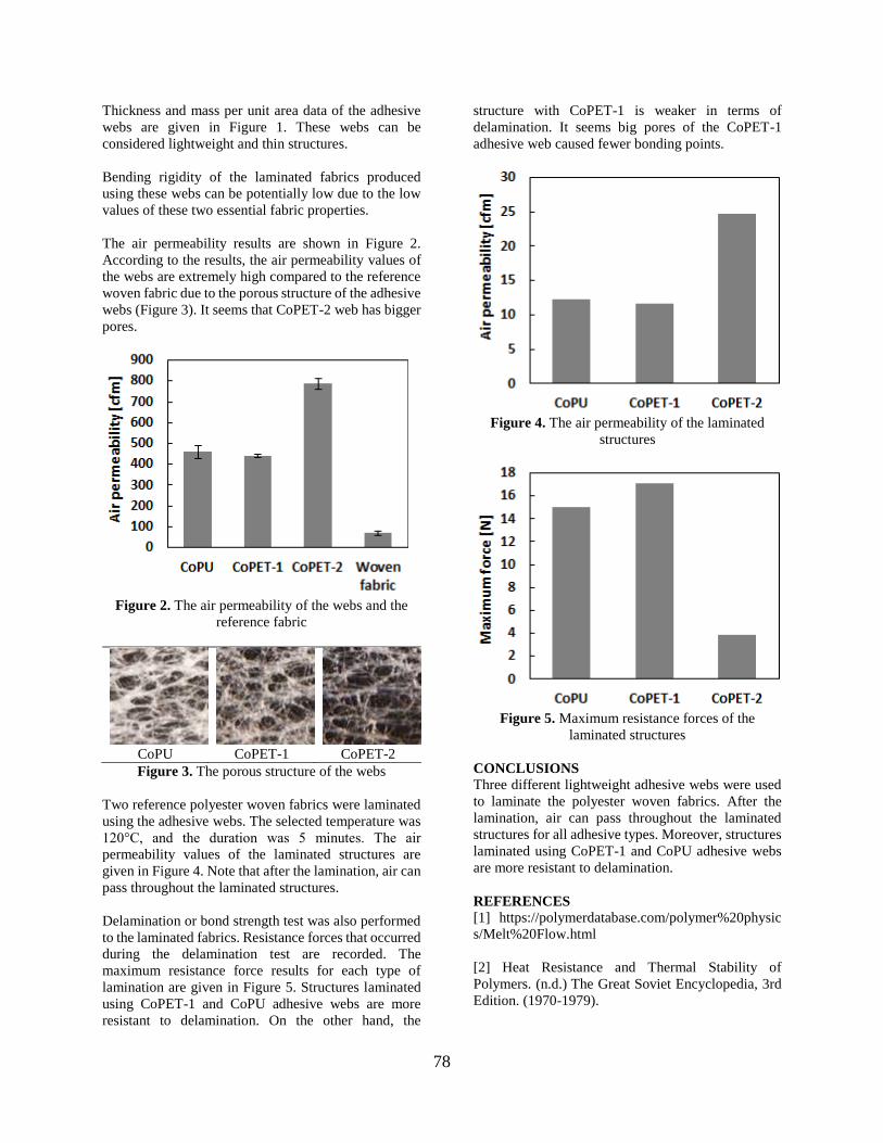
78
Thickness and mass per unit area data of the adhesive
webs are given in Figure 1. These webs can be
considered lightweight and thin structures.
Bending rigidity of the laminated fabrics produced
using these webs can be potentially low due to the low
values of these two essential fabric properties.
The air permeability results are shown in Figure 2.
According to the results, the air permeability values of
the webs are extremely high compared to the reference
woven fabric due to the porous structure of the adhesive
webs (Figure 3). It seems that CoPET-2 web has bigger
pores.
Figure 2. The air permeability of the webs and the
reference fabric
CoPU CoPET-1 CoPET-2
Figure 3. The porous structure of the webs
Two reference polyester woven fabrics were laminated
using the adhesive webs. The selected temperature was
120°C, and the duration was 5 minutes. The air
permeability values of the laminated structures are
given in Figure 4. Note that after the lamination, air can
pass throughout the laminated structures.
Delamination or bond strength test was also performed
to the laminated fabrics. Resistance forces that occurred
during the delamination test are recorded. The
maximum resistance force results for each type of
lamination are given in Figure 5. Structures laminated
using CoPET-1 and CoPU adhesive webs are more
resistant to delamination. On the other hand, the
structure with CoPET-1 is weaker in terms of
delamination. It seems big pores of the CoPET-1
adhesive web caused fewer bonding points.
Figure 4. The air permeability of the laminated
structures
Figure 5. Maximum resistance forces of the
laminated structures
CONCLUSIONS
Three different lightweight adhesive webs were used
to laminate the polyester woven fabrics. After the
lamination, air can pass throughout the laminated
structures for all adhesive types. Moreover, structures
laminated using CoPET-1 and CoPU adhesive webs
are more resistant to delamination.
REFERENCES
[1] https://polymerdatabase.com/polymer%20physic
s/Melt%20Flow.html
[2] Heat Resistance and Thermal Stability of
Polymers. (n.d.) The Great Soviet Encyclopedia, 3rd
Edition. (1970-1979).

79
Improving flame retardancy of PE with halogen-free
materials GUNAYDIN, Beyza Nur1, SEYHAN, Aybeniz1, POLAT, Yusuf1,2, KILIC, Ali1,3, DEMIR, Ali1,3,
UREYEN, Mustafa Erdem4,5, AVCI, Huseyin1,4
1TEMAG Labs, Textile Tech. and Design Faculty, Istanbul Tech. Uni., Istanbul, Turkey 2 Mechanical Engineering, Faculty of Engineering, Marmara Uni., Istanbul, Turkey
3 Textile Engineering, Textile Tech. and Design Faculty, Istanbul Tech. Uni., Istanbul, Turkey 4Advanced Technologies Research Centre (ITAM), Eskisehir Tech. Uni., Eskisehir, Turkey
5Department of Fashion and Textile Design, Eskisehir Tech. Uni., Eskisehir, Turkey 6 Metallurgical and Materials Engineering, Engineering - Architecture Faculty, Eskisehir
Osmangazi Uni., Eskisehir, Turkey
PURPOSE
Flame retardancy (FR) properties of linear low density
polyethylene (LLDPE) has been studied with different
halogen-free flame retardants of aluminium trioxide
(ATH), nanoclay and nanocrystalline cellulose. The
samples were produced by twin screw extruder. In
addition, to reveal the synergistic effect of
phosphorous-mineral containing additives with
ammonium polyphosphate (APP) and ATH (30%
ATH-10% APP) were used. Limiting oxygen index
(LOI) and micro combustion calorimeter (MCC) tests
were performed to compare untreated and treated
samples.
INTRODUCTION
Polyethylene (PE) is the most used polymer type in the
world. The ignition time of PE is relatively low
compared to other thermoplastics. It is classified as a
low smoke emission polymer but considering the high
peak heat release rate, it can be dangerous in the real
fire situations1. The ongoing combustion reactions in
the form of ignited droplets play a critical role in
accelerating fire. Therefore, flame retardancy and
thermal properties of PE should be improved in order
to widen the application areas. Flame retardant
additives are used to reduce or stop the ignition of
polymeric materials. Flame retardant property gains
importance especially in composite applications of high
performance fibers2. Although halogen based flame
retardants and combinations with antimony trioxide are
conventionally used in polymer applications because of
their low cost, acceptable efficiency and no significant
change in the physical performance of a polymer, there
are important problems in practice due to their
performance limitations, environmental and toxic
effects3. Thus, demand and studies on using halogen-
free flame retardants are rapidly grown4. Moreover,
decreasing the FR amount used in the polymer and nano
sized additive applications are becoming popular
subjects, recently4.
In this study, ATH, nanoclay and nanocrystalline
cellulose were used as halogen-free FRs and the
samples were produced by the twin screw extruder.
All the samples were subjected to LOI and MCC tests
to analyze and compare the flammability and heat
characteristics. At the last part, according to test
results, ATH-APP hybrid masterbatch was studied
with different ratios via melt spin line. The aim of
using the APP with ATH together is to decrease the
high amount requirements of ATH to obtain sufficient
flame retardancy properties for high performance PE
fibers by synergistic activity between ATH and APP.
EXPERIMENTAL
Material
The ASPUN™ 6000 linear low-density polyethylene
(LLDPE) (MFI, 19 and density, 0.935 g/cm3) was
obtained from Dow Chemical Company. 99.95% pure
ATH having a grain size of 20-25 µm from Entekno
Industrial Company; Cloisite-20 nanoclay with an
organic intercalated dry particle size <10µm and a
density of 1.77g/cm3 was Feza Chemical Company;
nanocrystalline cellulose (CNC) from Nanografi
Company having a density of 1.49 g/cm3 and diameter
of 10-20 nm and a length of 300-900 nm and Acar
Kimya ve Sanayi Tic. Ltd. Ltd. Şti., EXOLIT AP 422
APP were purchased.
Method
Micro-compounder with twin screw (DSM Xplore)
were used to produce samples according to TS 11162
EN ISO 4589 standard for LOI tests (Concept
Equipment). Hybrid filaments were produced by a
single screw extruder melt spin line with 0.6 mm
spinneret diameter. For the determination of thermal

80
behaviors of PE, MCC test was also performed to all
samples.
EXPERIMENTAL RESULTS AND
DISCUSSIONS
LOI results of samples prepared with different ATH
concentration demonstrated the addition of ATH
slowed down the burning at the same oxygen
concentration. But LOI value could not be improved
satisfactorily. Maximum LOI value (22.17%) was
obtained by 40% ATH.
Table 1. Comparison of the limiting oxygen index of
PE and PE-ATH with different additive amounts.
Samples ATH
(wt %)
PE
(wt %)
LOI
(%)
PE 0 100 19.00
PE-1 10 90 19.91
PE-2 20 80 20.91
PE-3 30 70 21.29
PE-4 40 60 22.17
Also, for other additives such as nanoclay and CNC, the
best LOI values were determined 20.30 and 19.30 at 10
wt%, respectively. In MCC test, heat release rate
(HRR), peak of heat release rate (pHRR), pHRR
temperature, heat release capacity (HRC) and total heat
release (THR) values were represented in Fig. 1.
According to the given MCC results, it is seen that the
amount of ATH positively affects the HRR of PE and
reduces HR capacity. Although the addition of nanoclay
had no effect on the LOI value, it was observed that the
combustion behavior and melt dripping property of the
polymer material was improved. Moreover, significant
char formation and flameless dripping were observed in
the burned polymer with the addition of cellulose
compared to the samples produced with nanoclay and
ATH.
Figure 1. Comparison of the MCC test results of PE
and PE-ATH with different additive amounts.
To reduce the ATH amount, APP was mixed with
ATH and ATH-APP hybrid in different ratios (5 wt%,
3 wt% and 2 wt%) were added to the system during
extrusion. APP is added in sufficient amounts, it has
the formation of charcoal, reduces the combustion
time of the polymers and prevents dripping.
CONCLUSIONS
Samples were separately made from flame retardant
additives by twin screw extruder. According to given
results, it was seen that nano additives did not affect
the LOI test results, unlike lowered the values instead
of raising them. ATH can show positive effect when
amounts to increased 40 wt.%. Thus, because of
requiring the high amounts, ATH alone is not
effective to produce high performance PE fibers.
Depending on the initial results, ATH-APP hybrid
was only feed to the melt spin line. The result of
adding APP, synergistic affect was observed and
ATH-APP hybrid structure demonstrated LOI values
of 20.
SUGGESTION FOR FURTHER WORK
Different hybrid studies will be investigated to
improve FR effects. After the optimization, the high
performance PE fibers with having FR properties will
be produced by our modified melt-spin line.
ACKNOWLEDGEMENTS OF FUNDING
The authors thank TUBITAK (Project
Number: 117Z673) for financially support to this
research. The authors also gratefully acknowledge
Dow Chemical Company for providing ASPUN™
6000 and Mimtek Makine San. Tic. A.Ş to provide
APP additive.
LITERATURE
1. Agwuncha, S. C., Ibrahim, I. D., & Sadiku, E. R.
(2017). Improving the thermal and flame resistance
properties of polyolefins. In Polyolefin Fibres (pp.
421-448). Woodhead Publishing.
2. Bourbigot, S., & Flambard, X. (2002). Heat resistance
and flammability of high performance fibres: A
review. Fire and materials, 26(4‐5), 155-168.
3. Avcı, H., Üreyen, M. E., Kiliç, A., Sağlam, A. E., &
Demir, A. Güç Tutuşur Polipropilen Polimeri Ve Lif
Uygulamalarinda Son Gelişmeler Ve Gelecek
Beklentileri. Uludağ University Journal of The
Faculty of Engineering, 24(2), 609-632.
4. Rault, F., Giraud, S., Salaün, F., & Almeras, X.
(2015). Development of a halogen free flame
retardant masterbatch for polypropylene fibers.
Polymers, 7(2), 220-234.

81
REAKTİF BOYALI PAMUKLU KUMAŞLARDA
KULLANILAN FİKSATÖR TİPLERİ VE
KOMPOZİSYONLARININ RENK HASLIĞI ÜZERİNE
ETKİSİ OĞUZ, Damla1, YILDIRIM, Kenan2
1Rudolf Duraner Kimyevi Mad. Tic. A.Ş., Bursa/Türkiye
2Bursa Teknik Üniversitesi, MDBF, Lif ve Polimer Mühendisliği Bölümü, Bursa/Türkiye
[email protected], [email protected]
AMAÇLAR
Bu çalışmanın amacı literatürde eksik olan fiksatör
tipleri ve karışımlarının reaktif boyarmaddeler ile
boyanmış pamuklu örme kumaşlara ait haslık değerleri
üzerine etkisinin incelenmesidir.
GİRİŞ
Pamuk lifi emiciliği ve konfor özellikleri sayesinde
oldukça tercih edilen ve tekstil üretiminin %50’den
fazlasında kullanılmakta olan bir lif tipidir. Tekstil
sektörü hayatımızın vazgeçilmezleri arasında yer
almakta olup üretilen mamüllerin renk haslık özellikleri
ürün kalitesi için önemli parametrelerden
biridir.Tecrübeler gösterir ki reaktif boyarmaddelerin
özellikle ışık haslık değerleri oldukça iyidir ancak yaş
haslık değerleri reaktif gruba ve substantifliğe bağlı
olarak orta dereceli olarak değerlendirilmektedir.1
Bu durumu iyileştirmek adına haslık özelliklerini
geliştirmekte kullanılan fiksatör olarak tanımlanan
polimerler ile ard işlemler yapılmaktadır. Fiksatörler,
selüloz ve boyarmadde arasında güçlü köprü oluşturur
ve bu sayede boyarmadde molekülleri elyaf yüzeyine
sabitlemektedirler.Fiksatörlerin haslık üzerine etkisinin
incelenmesine yönelik bir çok çalışma mevcuttur.2-5
DENEYSEL
Malzeme
Çalışmada bordo, siyah ve turkuaz olmak üzere 3 farklı
renkte %100 pamuklu örme kumaşlar kullanılmıştır.
Yöntem
Örme kumaşlar kısa ve uzun zincirli quaterner
poliamonyum, poliamin, poliamid, poliüretan ve
epiklorhidrin bazlı 6 adet fiksatör ile ard işleme tabi
tutulmuştur. Uygulama işleminde fiksatörlerin
kendileri ve karışım (%50+%50) halleri
kullanılmıştır. Banyo konsantrasyonu 15 g/l, pH
değeri 5-5.5 ve kumaşın çözeltiyi alma oranını ise
%85 olacak şekilde ayarlanmıştır. Emdirme yöntemi
ardından işlem gören kumaşlar ramda 140ºC’ de 2 dk
fikse işlemine tabi tutulmuştur. Sonuçlar hem göz ile
subjektif olarak hem de spektrofotometre cihazı ile
objektif olarak değerlendirilmiştir. Fiksatörün etkisi
görmek üzere Evsel ve Ticari Yıkamaya Karşı Renk
Haslığı (ISO 105 C06), ve Sürtmeye Karşı Renk
Haslığı (ISO 105 X12) testleri uygulanmıştır.Renk
haslık analizlerinin değerlendirilmesi refekat bezine
akma durumuna göre yapılmıştır. Akma seviyesi ise
refekat bezindeki pamuk lifine akma seviyesi olarak
ölçülmüştür.
DENEYSEL SONUÇLAR/TARTIŞMA
Bordo, siyah ve turkuaz renkte olan kumaşlar koyu
tonda oldukları için renk değişimi parametresi
bazında değerlendirme yapılamamıştır. Üç farklı
renkteki işlemli kumaşlara ait yıkamaya karşı renk
haslığı değerlerinin poliamin bazlı fiksatör ve
karışımlarında oldukça geliştiği gözlenmiştir.

82
Poliamin fiksatör ve karışımlarında ortalama olarak
bordo renkte 1,5 birim, turkuaz renkte 0,5 birim ve
siyah renkte ise 0,5 birim iyileştirdiği görülmüştür.
Sürtmeye karşı (yaş) haslık değerlerinde ise poliüretan
ve poliüretan/epiklorhidrin bazlı fiksatörler, bordo
rengi 2 birim, turkuaz rengi 0,5 birim, siyah rengi ise
1,5 birim iyileştirmiştir.
Tablo 1: Kumaşların renklendirilmesinde kullanılan boyar maddeler.
Bordo Reactive Red 239
Cosmos Red S-C (Bezaktiv)
Turkuaz Reactive Blue 181
Reactive Blue 21
Siyah
Yellow ED (Everzol)
Red ED- 7BN (Everzol) Setz. Black SNN (Everzol)
Tablo 2: Kumaşların renklendirilmesinde kullanılan boyar maddeler.
Fiksatör
tipleri 1 2 3 4 5 6
Epiklorhidrin
bazlı
15 - - - - -
Poliamin
reçine bazlı
- 15 - - - -
Poliamid
bazlı
- - 15 - - -
Kuaternar
amonyum
tuzları bazlı
(uzun
zincirli)
- - - 15 - -
Poliüretan
bazlı
- - - - 15 -
Kuaternar
amonyum
tuzları bazlı
(kısa
zincirli)
- - - - - 15
pH 5-5,5 5-5,5 5-5,5 5-5,5 5-5,5 5-5,5
Banyo alımı %85 %85 %85
%85
%85
%85
Kurutma
sıcaklığı
140oC 140oC
140oC
140C
140oC
140oC
Kurutma
süresi
2 dk 2 dk 2 dk 2 dk 2 dk 2 dk
GENEL SONUÇLAR
Bordo renkli kumaşların poliamin bazlı fiksatör ve bu
fiksatörün diğer fiksatörler ile karışımları ile fikse
edilmesi (ard işlem yapılması) durumunda; yıkamaya
karşı renk haslık değerlerini gözle yapılan
değerlendirmede 2-3’ den 4’ e yükselttiği, cihazla
yapılan değerlendirmede ise sadece poliamin bazlı
fiksatörün 3’ ten 4-5’ e, diğer fiksatör tipleri ile olan
karışımlarının ise 3’ten 4’ e yükselttiği gözlenmiştir.
Uzun zincirli kuaternar poliamonyum bazlı fiksatör
ise akma değerini 2-3’ ten 3-4’ e, cihazla
değerlendirmede ise 3’ ten 4’ e yükseltmiştir. Bu
fiksatör tipi ile epiklorhidrin, poliamin ve kısa zincirli
kuaternar poliamonyum bazlı fiksatör karışımlarının
uygulanması durumunda ise hem göz hem de cihaz ile
değerlendirmede haslık değerlerini +1-1,5 birim
arasında iyileştirdiği görülmüştür. Epiklorhidrin,
poliamid, poliüretan, kısa zincirli kuaternar
poliamonyum bazlı fiksatörlerin ise, yıkama haslık
değerlerinin gelişmesine olumlu yönde bir katkı
sağlamadıkları gözlenmiştir.
Turkuaz renkli kumaşların poliamin bazlı fiksatör ve
karışımları ile fikse edilmesi durumunda yıkamaya
karşı renk haslık değerlerini gözle değerlendirmede
4’ten 4-5’e yükselttiği ancak cihaz
değerlendirmesinde herhangi bir farkın oluşmadığı
görülmüştür. Diğer fiksatörler ve birbirleri ile olan
karışımlarının ise haslık değerleri gelişmesine olumlu
ya da olumsuz yönde herhangi bir katkı
sağlamadıkları gözlenmiştir.
Ard işlem öncesi siyah renkli kumaşa ait
multifiberdaki akma değeri 4-5 olup bu değer üst
sınırdadır. Ard işlemler sonrası fiksatörlerin
yıkamaya karşı renk haslık değerleri üzerine olumlu
ya da olumsuz yönde etkisi gözlenmemiş olup ard
işlem öncesi değer korunmuştur.
Bordo, turkuaz ve siyah her üç renkte de sürtmeye
karşı renk haslık analizinin kuru sürtme değerleri
gözle yapılan değerlendirme 4-5, cihaz ile yapılan
değerlendirme ise 5 olarak ölçülmüştür. Bu değerler

83
haslık değerleri olarak yüksek kabul edilen değerlerdir
ve tüm fiksatör tipleri ile yapılan ard işlemler
sonrasında da herhangi bir değişim göstermemiştir.
Bordo rengin yaş sürtme değerlerinde ise, poliüretan
bazlı fiksatör ve poliüretan/epiklorhidrin fiksatör
karışımları, haslık değerini gözle yapılan
değerlendirmede 2’ den 4’ e, cihazla yapılan
değerlendirme de ise 3’ ten 4-5’e, yükselterek, +2-2,5
birim artış sağlamıştır. Poliamid/poliüretan karışımı ise
haslık değerini gözle yapılan değerlendirmede 2’ den 3’
e çıkarırken cihazla yapılan değerlendirmede ise 3’ten
3-4’e yükseltmiştir. Diğer fiksatör ve karışımları ise
gözle değerlendirmede haslık değerini 2’den 2-3’e
yükseltirken cihazla değerlendirmede genel olarak
ciddi bir değişim göstermemiştir.
Turkuaz rengin yaş sürtme değerlerinde ise poliüretan
bazlı fiksatör ve poliüretan/epiklorhidrin karışımının
haslık değerini gözle yapılan değerlendirmede 4’ ten 4-
5’ e yükselttiği görülmüştür ancak cihaz ile yapılan
değerlendirmede herhangi bir değişim izlenememiştir.
Diğer fiksatör ve karışımlarının sürtme haslık değerleri
üzerine olumlu ya da olumsuz herhangi bir katkısı
bulunmadığı tespit edilmiştir.
Siyah rengin yaş sürtme değerlerinde ise, poliüretan
bazlı fiksatör ve poliüretan/epiklorhidrin karışımının
haslık değerini hem göz hem de cihaz ile yapılan
değerlendirmede 2-3’ten 4’e yükselttikleri görülmüştür.
Diğer fiksatörler ve karışımların gözle yapılan
değerlendirmede haslık değeri üzerinde olumlu ya da
olumsuz bir etkisinin olmadığı, cihaz ile yapılan
değerlendirme de ise, poliamid/uzun zincirli kuaternar
poliamonyum ve poliamid/kısa zincirli kuaternar
poliamonyum karışımlarının yaş sürtme değerini 2-3’
ten 2’ ye düşürdükleri görülmüştür.
SONRAKİ DÖNEM ÇALIŞMALARI
Fiksatör tür ve karışımlarının yünlü kumaşlara etkisinin
incelenmesi ve farklı boyarmaddeler üzerindeki etkisi
yine pamuklu kumaşlarda denenmesi kumaş renk
haslıklarındaki gelişmelere katkısı olacaktır
TEŞEKKÜR/BILGILENDIRME/FON
KAYNAĞI
Çalışmaların yapılması için firma alt yapısının
kullanımına izin verdiği ve proje masraflarnı
karşıladığı için Rudolf Duraner Kimyevi Mad. Tic.
A.Ş., Bursa/Türkiye firmasına teşekkür ederiz.
KAYNAKLAR
[1] Jamadhar, R., Daberao, A., Nadiger M.,
Chandrakar, K. 2017. ''Effect of Dyeing of
Cotton Fabric by Using Dye Fixing Agent'',
International Journal on Textile Engineering and
Processes, 3 (1), 51-53.
[2] He, W., Xu, H., Hu, Z. 2002. ''Synthesis and
Application of Reactive Pre-polyurethane Resin
Dye Fixing Agent'', Dye Printing, (6), 6-9.
[3] Hu, Y., Guo, R., Jia, S.T. 2009. ''Synthesis and
Application of Waterbased Polyurethane Dye
Fixing Agent'', Polyurethane Industry, 24 (1), 26-
29.
[4]https://tr.scribd.com/document/352385349/Dye-
Fixing-Problems [08Kasım 2018].
[5] Mughal, J. M., Saeed, R., Naeem, M., Ahmed,
A.M., Yasmien, A., Siddiqui, Q., Iqbal, M. 2013.
''Dye Fixation and Decolourization of Vinyl
Sulphone'', Journal of Saudi Chemical Society,
14, 23-26,. doi:10.1016/j.jscs.2011.02.017.
[6] Yakartepe, M., Yakartepe, Z. 1995. ''Tekstil
Terbiye Teknolojisi Kasardan Apreye'' İstanbul.
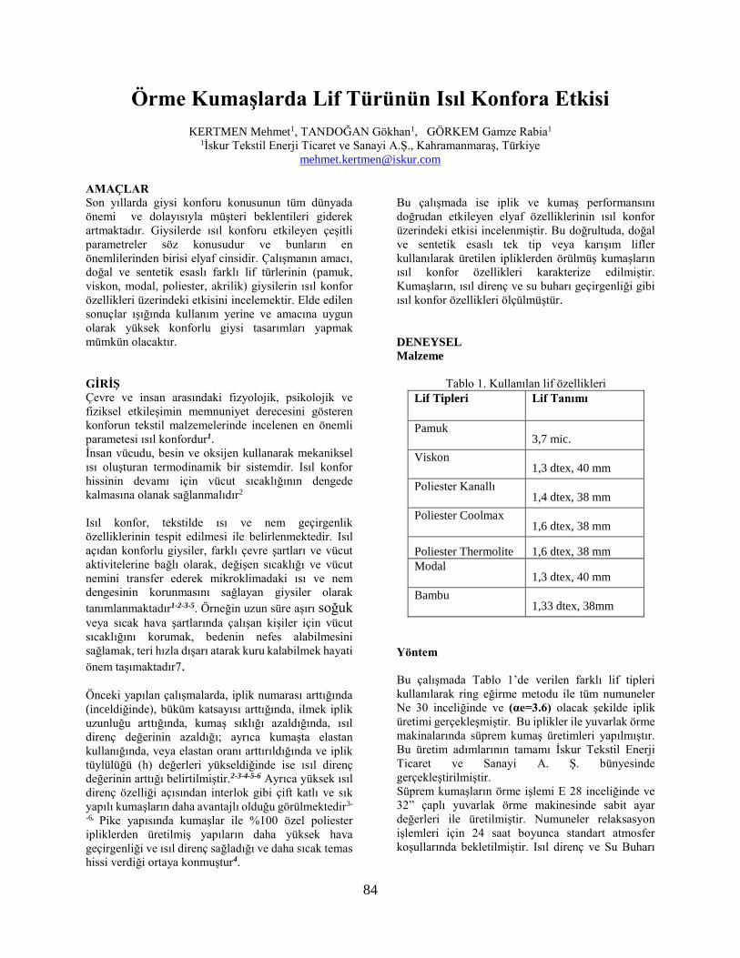
84
Örme Kumaşlarda Lif Türünün Isıl Konfora Etkisi
KERTMEN Mehmet1, TANDOĞAN Gökhan1, GÖRKEM Gamze Rabia1 1İskur Tekstil Enerji Ticaret ve Sanayi A.Ş., Kahramanmaraş, Türkiye
AMAÇLAR
Son yıllarda giysi konforu konusunun tüm dünyada
önemi ve dolayısıyla müşteri beklentileri giderek
artmaktadır. Giysilerde ısıl konforu etkileyen çeşitli
parametreler söz konusudur ve bunların en
önemlilerinden birisi elyaf cinsidir. Çalışmanın amacı,
doğal ve sentetik esaslı farklı lif türlerinin (pamuk,
viskon, modal, poliester, akrilik) giysilerin ısıl konfor
özellikleri üzerindeki etkisini incelemektir. Elde edilen
sonuçlar ışığında kullanım yerine ve amacına uygun
olarak yüksek konforlu giysi tasarımları yapmak
mümkün olacaktır.
GİRİŞ
Çevre ve insan arasındaki fizyolojik, psikolojik ve
fiziksel etkileşimin memnuniyet derecesini gösteren
konforun tekstil malzemelerinde incelenen en önemli
parametesi ısıl konfordur1.
İnsan vücudu, besin ve oksijen kullanarak mekaniksel
ısı oluşturan termodinamik bir sistemdir. Isıl konfor
hissinin devamı için vücut sıcaklığının dengede
kalmasına olanak sağlanmalıdır2
Isıl konfor, tekstilde ısı ve nem geçirgenlik
özelliklerinin tespit edilmesi ile belirlenmektedir. Isıl
açıdan konforlu giysiler, farklı çevre şartları ve vücut
aktivitelerine bağlı olarak, değişen sıcaklığı ve vücut
nemini transfer ederek mikroklimadaki ısı ve nem
dengesinin korunmasını sağlayan giysiler olarak
tanımlanmaktadır1-2-3-5. Örneğin uzun süre aşırı soğuk veya sıcak hava şartlarında çalışan kişiler için vücut
sıcaklığını korumak, bedenin nefes alabilmesini
sağlamak, teri hızla dışarı atarak kuru kalabilmek hayati
önem taşımaktadır7.
Önceki yapılan çalışmalarda, iplik numarası arttığında
(inceldiğinde), büküm katsayısı arttığında, ilmek iplik
uzunluğu arttığında, kumaş sıklığı azaldığında, ısıl
direnç değerinin azaldığı; ayrıca kumaşta elastan
kullanığında, veya elastan oranı arttırıldığında ve iplik
tüylülüğü (h) değerleri yükseldiğinde ise ısıl direnç
değerinin arttığı belirtilmiştir.2-3-4-5-6 Ayrıca yüksek ısıl
direnç özelliği açısından interlok gibi çift katlı ve sık
yapılı kumaşların daha avantajlı olduğu görülmektedir3-
-6. Pike yapısında kumaşlar ile %100 özel poliester
ipliklerden üretilmiş yapıların daha yüksek hava
geçirgenliği ve ısıl direnç sağladığı ve daha sıcak temas
hissi verdiği ortaya konmuştur4.
Bu çalışmada ise iplik ve kumaş performansını
doğrudan etkileyen elyaf özelliklerinin ısıl konfor
üzerindeki etkisi incelenmiştir. Bu doğrultuda, doğal
ve sentetik esaslı tek tip veya karışım lifler
kullanılarak üretilen ipliklerden örülmüş kumaşların
ısıl konfor özellikleri karakterize edilmiştir.
Kumaşların, ısıl direnç ve su buharı geçirgenliği gibi
ısıl konfor özellikleri ölçülmüştür.
DENEYSEL
Malzeme
Tablo 1. Kullanılan lif özellikleri
Lif Tipleri Lif Tanımı
Pamuk 3,7 mic.
Viskon 1,3 dtex, 40 mm
Poliester Kanallı 1,4 dtex, 38 mm
Poliester Coolmax 1,6 dtex, 38 mm
Poliester Thermolite 1,6 dtex, 38 mm
Modal 1,3 dtex, 40 mm
Bambu 1,33 dtex, 38mm
Yöntem
Bu çalışmada Tablo 1’de verilen farklı lif tipleri
kullanılarak ring eğirme metodu ile tüm numuneler
Ne 30 inceliğinde ve (αe=3.6) olacak şekilde iplik
üretimi gerçekleşmiştir. Bu iplikler ile yuvarlak örme
makinalarında süprem kumaş üretimleri yapılmıştır.
Bu üretim adımlarının tamamı İskur Tekstil Enerji
Ticaret ve Sanayi A. Ş. bünyesinde
gerçekleştirilmiştir.
Süprem kumaşların örme işlemi E 28 inceliğinde ve
32” çaplı yuvarlak örme makinesinde sabit ayar
değerleri ile üretilmiştir. Numuneler relaksasyon
işlemleri için 24 saat boyunca standart atmosfer
koşullarında bekletilmiştir. Isıl direnç ve Su Buharı

85
Geçirgenliği değerleri ISO 11092 standardına göre
Permetest cihazında ölçülmüştür.
DENEYSEL SONUÇLAR/TARTIŞMA
Tablo 2. Gramaj, ısıl direnç ve su buharı geçirgenliği
ölçüm sonuçları
Numune
Gram
aj
(g/m2)
İlmek
İplik
Uzunl
uğu
Isıl
Direnç
(m2
K/W)
Su Buharı
Geçirgenl
iği (%)
%100 Cotton 150 32 0,0104 63,79
%100 Bamboo 145 31 0,0075 68,51
%100 Modal 140 31 0,0074 68,36
%100 Viscose 145 31 0,0089 64,15
%100 PES 154 32 0,0110 54,97
% 100 Kanallı
PES 155 32 0,0116 61,74
% 100 Hallow
PES 144 32 0,0139 59,45
%50 Cotton
%50 Viscose 140 31 0,0099 58,28
%50 Cotton
%50 Bamboo 148 32 0,0084 61, 27
%50 Cotton
%50 Modal 150 32 0,0089 65,08
%50 Cotton
%50 Polyester 150 32 0,0124 54,97
%13 Cotton
%75 Polyester
%12 Viscose
150 32 0,0121 58,62
GENEL SONUÇLAR
Bu çalışma sonunda lif seçiminin ısıl konfor üzerinde
çeşitli etkileri olduğu gözlenmiştir.
• Hem rejenere selülöz lifleri ve hem de kanallı poliester
lifleri ile örülen kumaşların su buharı geçirgenliği
değerlerinin daha yüksek olduğu saptanmıştır.
•en yüksek ısıl direnç değerinin içi boşluklu polyester
(hollow fiber) liflerinden örülen kumaşa ait olduğu
görülmüştür. Bu liflerin içerisinde bulunan durgun
hava ısıl direncin yüksek olmasını sağlamıştır.
• Rejenere selüloz (%100 viskon, %100 modal, %100
bambu) ile üretilen kumaşlar ile daha düşük termal
direnç ölçülmüştür,
• Boşluklu poliester lifleri ile standart poliester liflerine
göre daha yüksek termal direnç sağlanmıştır.
• Bu verilere dayanarak, ısıl konfor açısından kışlık
kıyafetlerde boşluklu poliester ve % 100 pamuklu ya
da pamuklu karışım kıyafetler önerilirken, yazlık
kıyafetlerde rejenere selüloz ve karışımları ile kanallı
poliester yapısı önerilmektedir.
KAYNAKLAR
[1] Aydın I S, Kertmen M., Marmaralı A., 2017
"Evaluating the effect of spinning systems on thermal
comfort properties of modal fabrics" Journal of
Biological and Chemical Research, ISSN 2319-3077,
Vol.4, Issue 11, p265 – 27
[2] Ertekin, G., Oğlakcıoğlu, N., Marmaralı A., 2015
“Thermal Transmission Attributes of Knitted
Structures Produced by Using Engineered Yarns”
Journal of engineered fibers and fabrics. 72. 4-2015.
10.1177/155892501501000418.
[3] Gülsevin, N., 2005 Spor Giysilerin Konfor
Özellikleri Üzerine Bir Araştırma, Yüksek Lisans
Tezi, Ege Üniversitesi Fen Bilimleri Enstitüsü, İzmir
[4] Marmaralı A., Kadoğlu H., Oğlakcıoğlu N., Çelik
P., Blaga M., Ursache M., Loghin C., 2009, “Thermal
comfort properties of some new yarns generation
knitted fabrics”, In: Proceedings of the AUTEX 2009
World Textile Conference, 26–28 May 2009.
[5] Marmaralı A., Özdil N., Dönmez S., 2006,
"Giysilerde Isıl Konfor", Tekstil Teknik, No:9, 163-
167.
[6] Oğlakçıoğlu N., Marmaralı A., 2010 “Rejenere
Selüloz Liflerinin Kompresyon Çoraplarının Isıl
Konfor Özelliklerine Etkisi”, Tekstil ve Mühendis,
17(77), 6-12.
[7] Üte Bedez T., Çelik P., Kadoğlu H., ,Üzümcü B.,
Ertekin G., Marmaralı A., 2018 , Farkli Doğal
Liflerin İç Giysilerde Kullaniminin Konfor
Özellikleri Açisindan Araştirilmasi, Tekstil ve
Mühendis, Yıl 2018/4, Cilt : 2, Sayı: 112.

86
KARIŞIM KUMAŞLARDA PİLLİNG DEĞERLERİNİ
İYİLEŞTİREN FONKSİYONEL POLİMERİN TASARIMI,
SENTEZİ ve TEKSTİL UYGULAMALARI BÜYÜKKORU, Burcu 1,2, KARA, Ali 1
1Fen Fakültesi, Kimya Bölümü, Uludağ Üniv., Bursa, Türkiye 2Rudolf-Duraner, Bursa, Türkiye
[email protected],[email protected]
AMAÇLAR
Tekstil pazarında kullanılmak üzere kumaşların pilling
değerlerini iyileştiren, karışım kumaşlarda da etkili,
uygulandığı kumaşlardaki tuşeyi ve hidrofiliteyi
arttıran fonksiyonel polimerin tasarlanması ve
sentezlenmesi hedeflenmiştir. Sentezlenen polimerin
tekstil uygulamalarında başarı sağlamasının ardından
Rudolf-Duraner ürün gamında yer alması ve pazar
beklentisini karşılayacak bir ürün olarak satışa
sunulması amaçlanmıştır. Tekstil pazarında bu alanda
eksikliğin olması sebebiyle projede geliştirilen
fonksiyonel polimer ile yüksek satış rakamlarına
ulaşılacağı öngörülmektedir.
GİRİŞ
Tekstil yardımcı kimyasalları üreten firmaların efekt
bölümlerindeki başlıca çalışma konularından biri;
pilling azaltıcı ürünler tasarlamak, üretmek ve satışını
gerçekleştirmektir. Tekstil pazarında oldukça ilgi gören
bu alana yönelik epey çalışma ve ürün vardır. Bu
ürünler genellikle enzim ya da poliüretan içeren
kimyasallardır. Ancak söz konusu kimyasallar, pazar
beklentilerini yeterince karşılayamamaktadır. Bunun
temel sebebi, bu kimyasalların karışım kumaşlarda
istenilen pilling iyileştirme değerlerini
sağlayamamasıdır. Karışım olmayan kumaşlarda etkili
olup pilling değerlerini iyileştiren enzimlerin hem
fiyatının pahalı kalması hem de istenilen yumuşaklık
efektini kumaşlara kazandıramaması sebebiyle
piyasada alternatif ürün arayışları devam etmektedir.
Enzim içermeyen bazı kimyasallar literatürde ve
pazarda mevcuttur. Bu kimyasallar genellikle
poliüretanlardır. Pilling değerlerini iyileştirmeye katkı
sağlayan bu alanda kullanılabilen poliüretanlar kimyası
gereği kumaşlara sert bir tuşe vermektedir. Ayrıca
enzimlerin ve poliüretanların kumaşa aplikasyonundan
sonra kumaşların hidrofiliteleri de geriye gitmektedir.
Bu sebeple, hem hidrofilitesi ve tuşesi iyi hem anti-
pilling özelliği olan alternatif ürüne piyasada ihtiyaç
duyulmaktadır.
Bu çalışma kapsamında, enzim veya poliüretan
kullanmadan fonksiyonel bir polimer ile istenilen
özellikleri kumaşlara kazandıran ürün piyasaya
sunulacaktır.
Piyasadaki anti-pilling ürünleri fular ya da kaplama
teknikleri ile kumaşa aplike edilmektedir. Projede
geliştirilen fonksiyonel polimer de bu yöntemlere
uygun olup fular ve kaplama aplikasyonları ile
kumaşa uygulanabilecektir.
Yün, pamuk, viskoz gibi kopma ve aşınma dayanımı
düşük olan liflerde boncuklar daha yüksek kopma
mukavemeti, esneme mukavemeti ve aşınma
direncine sahip sentetik liflere kıyasla sürtünme ile
yüzeyi daha kolay terk ederler.
Hidrofil elyafa nazaran hidrofobik lifler elektrostatik
özelliklerine bağlı olarak yabancı maddeleri çekmeye
daha yatkındırlar. Kumaş yüzeyine tutunan liflere
göre kopmuş ve karmaşıklaşmış lifler daha kısadırlar.
Tutucu lifler en güçlü lifler iken kopmuş ve
karmaşıklaşmış lifler en ince ve esnek liflerdir. Örme
kumaşlar, dokuma kumaşlara göre daha fazla
boncuklanma eğilimindedirler.
Kumaşın kötü görünmesinin yanı sıra, boncuklanma
bazen delik oluşumuna kadar giderek giysilerin
yıpranması nedeniyle kullanma süresinin kısalmasına
neden olmaktadır.
Kumaşların pilling oluşumlarının tespit edilmesi için
bir çok yöntem geliştirilmiştir. ISO 12945-2 standardı
esas alınarak Martindale Pilling cihazının kullanımı
çok yaygındır. Yöntemde 150 mm çapında kumaş
numuneleri kullanılır. Lissajous hareketi ile test
gerçekleştirilir. Bu harekette, üst numunelerin
hareketi, dairesel hareketle başlayıp, yavaş yavaş
daralan elips şeklinden doğrusal hale gelinceye kadar
devam eden ve sonra da ters yönde genişleyen elips
şeklindeki hareketle devam eder. Programlanmış
hareket ve sabit basınç test sonuçlarına yüksek
tekrarlanabilirlik güvencesi sağlamaktadır.
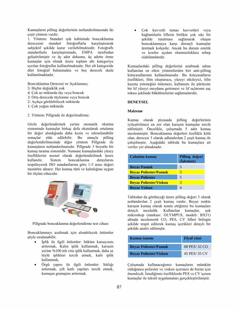
87
Kumaşların pilling değerlerinin notlandırılmasında iki
çeşit yöntem vardır.
1. Yöntem: Standart ışık kabininde boncuklanma
derecesini standart fotoğraflarla karşılaştırarak
subjektif şekilde karar verilebilmektedir. Fotoğraflı
standartlarla karşılaştırmada, EMPA tarafından
geliştirilmiştir ve üç adet dokuma, üç adette örme
kumaşlar için olmak üzere toplam altı kategoriye
ayrılan fotoğraflar kullanılmaktadır. Her alt kategoride
dört fotoğraf bulunmakta ve beş dereceli skala
kullanılmaktadır.
Boncuklanma Derecesi ve Açıklaması;
5: Hiçbir değişiklik yok
4: Çok az miktarda tüy veya boncuk
3: Orta derecede tüylenme veya boncuk
2: Açıkça görülebilecek miktarda
1: Çok yoğun miktarda
2. Yöntem: Pillgrade ile değerlendirme;
Gözle değerlendirmek yerine otomatik okutma
sisteminde kumaşlar birkaç defa okutularak ortalama
bir değer alındığında daha kesin ve tekrarlanabilir
sonuçlar elde edilebilir. Bu amaçla pilling
değerlendirilmesinde diğer yöntem Pillgrade ile
kumaşların notlandırılmasıdır. Pillgrade 3 boyutlu bir
kumaş tarama sistemidir. Numune kumaşlardaki yüzey
özelliklerini nesnel olarak değerlendirilmek üzere
kullanılır. Sistem boncuklanma detaylarını
tespitleyerek ISO standartlarına göre 1-5 arası değeri
monitöre aktarır. Her kumaş türü ve kalınlığına uygun
bir ölçüm cihazıdır.
Pillgrade boncuklanma değerlendirme test cihazı
Boncuklanmayı azaltmak için alınabilecek önlemler
şöyle sıralanabilir;
İplik ile ilgili önlemler: büküm katsayısını
arttırmak, Kalın iplik kullanmak, karışım
yerine %100 tek cins iplik kullanmak, daha az
tüylü iplikleri tercih etmek, katlı iplik
kullanmak,
Örgü yapısı ile ilgili önlemler: Sıklığı
arttırmak, çift katlı yapıları tercih etmek,
kumaşın gramajını arttırmak.
Çok kuvvetli temas kuvvetleri veya
bağlantılarla liflerin birlikte çok sıkı bir
şekilde tutulması sağlanarak oluşan
boncuklanmaya karşı dirençli kumaşlar
üretmek kolaydır. Ancak bu durum estetik
ve konfor açıdan olumsuzluklara sebep
olabilmektedir.
Kumaşlardaki pilling değerlerini azaltmak adına
kullanılan en etkin yöntemlerden biri anti-pilling
kimyasallarının kullanılmasıdır. Bu kimyasalların
özellikleri, film oluşturucu, yüzeyi etkileyici, lifin
kayma yeteneğini önlemesi, kullanımı ile pürüzsüz
bir lif yüzeyi meydana getirmesi ve lif uçlarının saç
tokası şeklinde bükülmelerini sağlamalarıdır.
DENEYSEL
Malzeme
Kumaş olarak piyasada pilling değerlerinin
iyileştirilmesi en zor olan karışım kumaşlar tercih
edilmiştir. Öncelikle, çalışmada 5 adet kumaş
incelenmiştir. Boncuklanma değerleri özellikle kötü
olan, derecesi 3 olarak adlandırılan 2 çeşit kumaş ile
çalışılmıştır. Aşağıdaki tabloda bu kumaşlara ait
veriler yer almaktadır.
Çalışılan kumaş Pilling değeri
(İşlemsiz)
Beyaz Pamuk 5
Beyaz Poliester/Pamuk 3
Beyaz Poliester 5
Beyaz Poliester/Viskon 3
Beyaz Viskon 4
Tablodan da görüleceği üzere pilling değeri 3 olarak
notlandırılan 2 çeşit kumaş vardır. Beyaz renkte
karışım kumaş olarak temin ettiğimiz bu kumaşları
detaylı inceledik. Kullanılan kumaşlar, ışık
mikroskop (markası: OLYMPUS, modeli: BX51)
altında incelenerek CO, PES, CV lifleri belirgin
şekilde tespit edilerek kumaş içerikleri detaylı bir
şekilde analiz edilmiştir.
Kumaş tanımı Elyaf cinsi
Beyaz Poliester/Pamuk 68 PES/ 32 CO
Beyaz Poliester/Viskon 45 PES/ 55 CV
Çalışmada kullanacağımız kumaşların mümkün
olduğunca poliester ve viskon içermesi de bizim için
önemliydi. İstediğimiz özelliklerde PES ve CV içeren
kumaşlar ile tekstil uygulamaları gerçekleştirilmiştir.

88
Tasarlanan polimerin elde edilmesi için RD Mon 2
tedarik edilerek bu monomer, uygun başlatıcı ve çözücü
kullanılarak serbest radikal polimerizasyonuna tabii
tutulmuştur. Burada kullanılan kimyasalların neler
olduğunu şirket gizliliği için burada paylaşamıyoruz.
Özetle monomer, çözücü ve katalizör ile fonksiyonel
polimer sentezlenmiştir.
Yöntem
Pilling azaltıcı etki sağlayacağı düşünülen polimer
tasarlanarak sentezlenecektir. Polimer sentezinin başarı
ile gerçekleştirilmesinin ardından tekstil uygulamaları
için gereken miktarda polimer sentezlenerek ürün
çoğaltılacaktır.
Polimerin çeşitli kumaşlarda fular aplikasyonu
yapılacaktır. Fularda kullanılacak kimyasal çeşitli
konsantrasyonlarda hazırlanarak optimum uygulama
miktarı belirlenecektir. Aplikasyon sırasında
kullanılacak fular makinasındaki basınç kumaşlarda
%65 pick-up değeri elde edilecek şekilde
ayarlanacaktır. Fular makinasından çıkan kumaşlar ram
yardımıyla 130°C’de kurutulacak ve şartlandırma
odasında bir gün bekletilecektir.
Hazırlanan kumaşlar pilling testine tabii tutulacaktır.
Pilling değerinde olumlu sonuç alınan kumaşların tuşe
ve hidrofiliteleri de değerlendirilecektir. Bu testlerden
de başarı ile geçen kumaşlara optik beyazlık testi
uygulanararak polimerin kumaşlarda sararmaya yol
açıp açmadığı görülecektir.
Bütün bu çalışmalar piyasada mevcut olan muadil
ürünlerle de gerçekleştirilerek sonuçlar kıyaslanacak ve
geliştirilecek fonksiyonel polimerlerin etkisi net bir
biçimde ortaya konmuş olacaktır.
Yapılan tüm testlerin ardından başarı sağlanırsa
fonksiyonel polimer firmanın ürün gamında yer alarak
satışa sunulacaktır. Her zaman aynı kalitede ürün elde
etmek amacıyla polimerin kalite kontrol spektleri
belirlenecektir. Ayrıca FT-IR, NMR, TGA, GPC
analizleri yapılarak ürün karakterize edilecektir.
DENEYSEL SONUÇLAR/TARTIŞMA
Sentez: RD Mon 2 kullanılarak uygun başlatıcı ve
çözücü ile serbest radikal polimerizasyonu ile polimer
elde edildi. Polimere EPW 18042 kodu verilmiştir.
Stabilite testi: Polimerin sulu çözeltilerinin
hazırlanarak ürün haline getirilmesinden sonra, oda
koşullarında kavanoz içerisinde bekletilerek ayrışıp
ayrışmadığı gözle takip edilmiştir, ürün stabildir.
pH değeri ölcümleri: Hedefimiz, nihai polimerin
ürün haline geldikten sonra pH değerinin 5,0-5,5
civarında olması idi. Reçetelere asetik asit eklenerek
pH ayarlanmıştı. pH metre ile yapılan kontroller ile
ürünün pH değeri istenilen aralıkta çıkmıştır.
FTIR analizleri: Ar-Ge merkezimizde bulanan FTIR
cihazı ile sentezlenen polimerin analizi yapılarak
istenilen pikler cihazda görülmüştür.
Viskozite ölcümü: Polimerin sulu çözeltilerinin
hazırlanarak ürün haline gelmesi aşamasında eklenen
su miktarına bağlı olarak viskozite epey
değişmektedir. Genel olarak ürünlerin viskozitesi 20-
500 mPas arasındadır.
Gel permeation chromatography (GPC): Rudolf-
Duraner Ar-Ge merkezindeki GPC cihazı ile
polimerin analizleri gerçekleştirilerek istenilen
piklerin elde edildiği görülmüştür.
Çevresel etkilere yönelik analiz çalışmalarında,
Rudolf-Duraner Ar-Ge merkezi ürün güvenliği
bölümü altında çalışan personelimizden destek
alınarak bu çalışmalar yapılmıştır. Polimerlerin
sentezinde kullanılan tüm kimyasallar kendilerine
iletilmiş ve çevresel etkilere yönelik analiz
çalışmaları sonuçları alınmıştır. Polimerin sentezi için
kullanılacak kimyasalların ve elde edilen polimerin
tekstil uygulamalarında kullanılmasında bir sakınca
yoktur.
Polimerin sentezinden sonra 5, 20, 40 g/l
konsantrasyonlarda EPW 18042 hazırlanarak
kumaşlara fular aplikasyonu yapılmıştır. Bu
kumaşlar, Martindale cihazı ile pilling testine tabii
tutulmuştur. Elde edilen pilling değerleri aşağıdaki
tablodaki gibidir.
Uygulanan Kumaş Sonuc İşlemsiz
EPW 18042
(40 g/l)
PES/CO 4-5 3
EPW 18042
(20 g/l)
PES/CO 4 3
EPW 18042
(5 g/l)
PES/CO 3-4+ 3
EPW 18042’nin PES/CO kumaşlara farklı
miktarlarda fular aplikasyonu sonucu kumaşlardaki
pilling değerleri
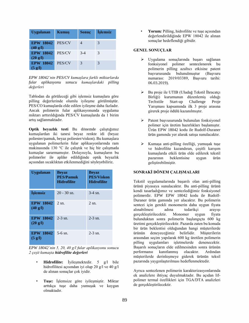
89
Uygulanan Kumaş Sonuc İşlemsiz
EPW 18042
(40 g/l)
PES/CV 4 3
EPW 18042
(20 g/l)
PES/CV 3-4 3
EPW 18042
(5 g/l)
PES/CV 3 3
EPW 18042’nin PES/CV kumaşlara farklı miktarlarda
fular aplikasyonu sonucu kumaşlardaki pilling
değerleri
Tablodan da görüleceği gibi işlemsiz kumaşlara göre
pilling değerlerinde olumlu iyileşme görülmüştür.
PES/CO kumaşlarda elde edilen iyileşme daha fazladır.
Ancak polimerin fular aplikasyonunda uygulama
miktarı arttırıldığında PES/CV kumaşlarda da 1 birim
artış sağlanmaktadır.
Optik beyazlık testi Bu dönemde çalıştığımız
kumaşlardan iki tanesi beyaz renkte idi (beyaz
poliester/pamuk, beyaz poliester/viskon). Bu kumaşlara
uygulanan polimerlerin fular aplikasyonlarında ram
makinasında 130 °C ile çalıştık ve hiç bir çalışmada
kumaşlar sararmamıştır. Dolayısıyla, kumaşların bu
polimerler ile aplike edildiğinde optik beyazlık
açısından sıcaklıktan etkilenmediğini söyleyebiliriz.
Uygulanan Beyaz
PES/Pamuk
Hidrofilite
Beyaz
PES/Viskon
Hidrofilite
İşlemsiz 20 - 30 sn. 3-4 sn.
EPW 18042
(40 g/l)
2 sn. 2 sn.
EPW 18042
(20 g/l)
2-3 sn. 2-3 sn.
EPW 18042
(5 g/l)
5-6 sn. 2-3 sn.
EPW 18042’nin 5, 20, 40 g/l fular aplikasyonu sonucu
2 çeşit kumaşta hidrofilite değerleri
• Hidrofilite: İyileşmektedir. 5 g/l bile
hidrofilitesi açısından iyi olup 20 g/l ve 40 g/l
de alınan sonuçlar çok iyidir.
• Tuşe: İşlemsize göre iyileşmiştir. Miktar
arttıkça tuşe daha yumuşak ve kaygan
olmaktadır.
• Yorum: Pilling, hidrofilite ve tuşe açısından
değerlendirildiğinde EPW 18042 ile alınan
sonuçlar hedeflendiği gibidir.
GENEL SONUÇLAR
Uygulama sonuçlarında başarı sağlanan
fonksiyonel polimer sentezlenerek bu
polimerin pilling azaltıcı etkisine patent
başvurusunda bulunulmuştur (Başvuru
numarası: 2019/03389, Başvuru tarihi:
06.03.2019).
Bu proje ile UTIB (Uludağ Tekstil İhracatçı
Birliği) kurumunun düzenlemiş olduğı
Techxtile Start-up Challenge Proje
Yarışması kapsamında ilk 3 proje arasına
girerek proje ödülü kazanılmıştır.
Patent başvusurunda bulunulan fonksiyonel
polimer için üretim hazırlıkları başlamıştır.
Ürün EPW 18042 kodu ile Rudolf-Duraner
ürün gamında yer alarak satışa sunulacaktır.
Kumaşa anti-pilling özelliği, yumuşak tuşe
ve hidrofilite kazandıran, çeşitli karışım
kumaşlarda etkili ürün elde edilerek tekstil
pazarının beklentisine uygun ürün
geliştirebilmiştir.
SONRAKİ DÖNEM ÇALIŞMALARI
Tekstil uygulamalarında başarılı olan anti-pilling
ürünü piyasaya sunulacaktır. Bu anti-pilling ürünü
kendi tasarladığımız ve sentezlediğimiz fonksiyonel
polimerdir. EPW EPW 18042 kodu ile Rudolf-
Duraner ürün gamında yer alacaktır. Bu polimerin
sentezi için gerekli monomerin daha uygun fiyata
alınabilmesi adına tedarikçi arayışı
gerçekleştirilecektir. Monomer uygun fiyata
bulunduktan sonra polimerin başlangıçta 600 kg
üretimi gerçekleştirilecektir. Pazarda zaten bu konuda
bir ürün beklentisi olduğundan hangi müşterilerde
ürünün deneyeceğimiz belirlidir. Müşterilerin
arasından seçim yapılarak 600 kg üretilen polimerin
pilling uygulamları işletmelerde denenecektir.
Başarılı sonuçların elde edilmesinden sonra ürünün
performansı kanıtlanmış olacaktır. Ardından
müşterilerde derinleşmeye giderek ürünün teksil
pazarında yaygınlaştırılması hedeflenmektedir.
Ayrıca sentezlenen polimerin karakterizasyonlarında
ek analizlere ihtiyaç duyulmaktadır. Bu açıdan lif-
polimer termal özellikleri için TGA/DTA analizleri
de gerçekleştirilecektir.
90
TEŞEKKÜR/BİLGİLENDİRME/FON KAYNAĞI
Bu çalışma Rudolf Duraner ve Uludağ Üniversitesi iş
birliğinde yürüyen TÜBİTAK-TEYDEB projesidir. Bu
iş birliğine katkı sağlayan TÜBİTAK’a desteklerinden
dolayı teşekkür ederiz.
KAYNAKLAR
Aksoy, S.A., Genç, E. 2015. Functionalization of cotton
fabrics by esterification cross-linking with 1,2,3,4-
butanetetracarboxylic acid (btca), Cellulose Chemistry
And Technology, 49 (5-6): 405-413.
Annis, P.A., 1996. “Pilling Evaluation of Laboratory
Abraded, Laundered, and Worn Fabrics Using Image
Analysis”, Book of papers International Conference
and Exhibition American Association of Textile
Chemists and Colorists, 465-479.
Dalbaşı, E. S., Kayseri, G.Ö. 2015. Research About The
Effect Of The Antipilling Treatments On Different
Structured Cotton Knitted Fabrics. Tekstil Ve
Konfeksiyon, 25: 54-60.
Furferi, R., Governi, L., Volpe, Y., 2012. “A novel
method for ring spinning performance evaluation based
on Computer Aided analysis of yarn geometry”,
International Journal of Mechanics, 6 (4), 212-221.
Kowalczyk, D., Brzezinski, S., Kaminska, I. 2015.
Multifunctional bioactive and improving the
performance durability nanocoatings for finishing
PET/CO woven fabrics by the sol-gel Method. Journal
of Alloys and Compounds, 649: 387-393.
Li L., Jia G., Zhou W., 2009. Effect of Yarn Properties
on the Pilling of Cashmere Knitted Fabric. Fibres &
Textiles in Eastern Europe, Vol. 17, No. 6 (77) pp. 76-
79.
Lv, H.N., Chen, Z.J., Xue, Y., Cai, Z.S. 2010. Synthesis
and application of waterborne polyurethane on the anti-
pilling finishing of wool fabrics, Proceedings Of The
12th International Wool Research Conference (IWRC
2010), Shanghai, China.
Man, L. W., Raymand, 2009. Mechanisms of pilling
formation and reduction by attrition methods, The Hong
Kong Polytechnic University Institute of Textiles &
Clothing.
Schidler, W.D., Houser, P.J., 2004. Chemical
Finishing of Textiles, Wood Head Publishing,
Cambridge, England, 129.
Ukponmwan, J.O., Mukhopadhyay, A., Chatterjee,
K.N. 1998. Pilling, Textile Progress, The Textile
Institute, 28: 1-57.
Wang, X.Y., Gong, R.H., Dong, Z., Porat, I. 2007.
Abrasion resistance of thermally bonded 3D
nonwoven fabrics. Science Direct, Wear, 262: 424–
431.
Zilz, L., Rau, M., Budag, N., Scharf, M., Cavaco-
Paulob, A., Andreausa, J. 2012. Nonionic surfactants
and dispersants for biopolishing and stonewashing
with Hypocrea jecorina cellulases. Society of Dyers
and Colourists, Color. Technol., 129: 49–54.
Zia, K.M., Zubera, M., Rizwana, A., Jamilb, T.,
Tabasuma, S., Shahidc, M. 2012. Modification of
cellulosic fabric using polyvinyl alcohol.
Carbohydrate Polymers, 87: 2063– 2067.

91
Mikroemülsiyon Yöntemi ile Limon Yağı İceren Aromatik
Mikrokapsül Üretimi ve Tekstil Uygulaması KOPTUR TASAN, Perinur1, YILDIRIM, Filiz2, ELİBÜYÜK ARAS, Sultan, YUMRU, Şaban, ÇÖREKCİOĞLU,
Mustafa, ALAY AKSOY, Sennur 1,2,3,4,5Ozanteks Tekstil, 6Süleyman Demirel Üniversitesi Tekstil Mühendisliği Bölümü
AMAÇLAR
Tekstil ürünlerine hoş koku, aroma terapi gibi özellikler
kazandırmak amacıyla biyo uyumlu doğal içerikli
maddelerin mikroemülsiyon yöntemi ile kapsüllenmesi
ve tekstil ürünlerine aplikasyonu amaçlanmaktadır.
GİRİŞ
Günümüzde tüketiciler, tekstil ürünlerinden temel
özelliklerinin yanında sağlık ve güzelliği koruması,
yaşam kalitesini arttırması, doğal olması gibi ekstra
fonksiyonlara da sahip olmasını, tüm bunları
gerçekleştirirken, insana ve çevreye zarar vermemesini
beklemektedir. Ayrıca küreselleşen dünya pazarında
artan rekabet, tekstil sektörünü katma değeri yüksek
fonksiyonel ürünlerin üretimine zorlamaktadır. Tekstil
materyallerine fonksiyonellik lif üretiminde
yapılabildiği gibi çoğunlukla da bitim işlemleri ile
kazandırılmaktadır. Mikrokapsülasyon teknolojisi
tekstillerin fonksiyonelleştirilmesinde kullanılan
teknolojilerden birisidir. Mikrokapsülasyon
teknolojisinden yararlanılarak farklı bileşenler ihtiva
eden mikrokapsüllerin üretimi ve tekstil materyallerine
aplikasyonu ile farklı fonksiyonel özelliklerde
tekstillerin üretimi mümkündür.
Mikrokapsüller, boyutları 1 μm ile 1 mm arasında
değişen, çekirdek ve duvar maddesinden oluşan
partiküllerdir1. Farklı tür maddeler farklı pek çok amaç
için mikrokapsüllenebilmektedir. Koku maddesinin
mikrokapsüllenmesindeki amaç onu uygun olmayan
çevre koşullarına karşı korumak, kontrollü ve yavaş
salınımını sağlamaktır2.Koku maddeleri uçucu
özelliklerinden dolayı tekstil materyaline direkt olarak
aplike edilememektedir. Bu maddeler ısı, nem ve diğer
dış etkenler nedeniyle buharlaşarak uzaklaşmalarını
önlemek, kokunun uzun süre kullanılması ve yavaş
salınımı amacıyla polimerik duvar materyali içerisine
kapsüllenmektedirler1,3. Aromatik mikrokapsül içeren
tekstil ürünleri giysi, ev tekstilleri vb. ürünlerde
aromaterapi özellikleri nedeniyle ilgi görmektedirler. Bu çalışmada, aromatik mikrokapsüllerin üretimi ve
kumaşa aplikasyonu çalışmaları gerçekleştirilmiştir.
Mikrokapsül üretimi mikroemülsiyon yöntemi ile
gerçekleştirilmiştir. Üretilen mikrokapsüllerin emdirme
yöntemi ile pamuklu kumaşlara aplikasyonu
sağlanmıştır. Kapsül oluşumu ve morfolojisini
incelemek için mikrokapsüllerin optik mikroskop
görüntüleri alınmıştır. Pamuk elyafına kapsüllerin
tutunma özelliğini incelemek için mikrokapsülasyon
aplikasyonu ve 5 yıkama sonrası kumaş SEM
(Taramalı Elektron Mikroskobu) görüntüleri
alınmıştır.
DENEYSEL
Malzeme
Çalışmalarda çekirdek malzeme olarak limon yağı,
duvar yapısı için doğal polimer olan arap zamkı
(Merck), emülsiyon oluşturmak için yüzey aktif
madde olarak Triton X, çapraz bağlayıcı olarak
gluteraldehit çözeltisi (%25) ve pH ayarlaması için
sodyum karbonat kullanılmıştır. Mikrokapsüllerin
tekstil ürününe aplikasyonunda %100 pamuklu
dokuma kumaş ve binder olarak Crilotan 300
(Bozzetto Group) kullanılmıştır.
Yöntem
Mikrokapsül üretiminin ilk aşaması kapsüllenecek
çekirdek maddenin su fazını oluşturan polimer
çözeltisi için de emülsiyonlaştırılması sağlanmıştır.
Bu amaçla arap zamkı çözeltisi içinde kapsüllenecek
limon yağı, bir emülsiyonlaştırıcı (Triton X 100)
varlığında yağ damlaları halinde dağıtılarak su içinde
yağ emülsiyonu elde edilmiştir. Emülsiyon sistemi
Oluşan çekirdek damlaları etrafına çözelti halindeki
polimerin depozite edilebilmesi için CaCl2 reaksiyon
ortamına ilave edildi. Ardından, çözelti sıcaklığı
4°C’ye, pH da 8-9 aralığına ayarlanarak oluşan
mikrokapsül duvar yapısının stabilitesini artırmak
için polimer molekülleri arasındaki çapraz bağlanma
reaksiyonlarının gerçekleştirecek gluteraldehit
reaksiyon ortamına ilave edilmiştir. Reaksiyonun
tamamlanmasından sonra mikrokapsül sulu çözeltisi
kumaşlara uygulanmak üzere hazırlanmıştır.
Mikrokapsüllerin kumaşa bağlanması için 1100C’de 2
d kurutma ve 1200C’de 2 d fikse uygulaması
yapılmıştır.
DENEYSEL SONUÇLAR/TARTIŞMA
Mikrokapsül oluşumunu gözlemlemek için
oluşturulan emülsiyon çözeltisinden mikroskop
altında görüntüler alınmıştır. Şekil 1’de
mikrokapsüllerin optik mikroskop ile alınan

92
görüntüleri verilmiştir. Görüntülerden küresel yapılı,
tanecikli mikrokapsül yapısının oluşumu
görülmektedir.
Şekil 1: Mikrokapsüllerin 100x büyütme oranında optik
mikroskop görüntüsü.
Mikrokapsüllerin pamuklu kumaşa aplikasyonu sonrası
kumaşlardan SEM görüntüsü alınmıştır. Şekil 2’de
mikrokapsüllerin pamuk lifi üzerindeki görüntüleri
verilmiştir. SEM görüntüsü incelendiğinde
mikrokasüllerin küresel morfolojili oldukları, parçacık
boyutlarının 10 µm’den daha küçük ve homojen boyut
dağılımlarına sahip olduğu görülmektedir.
Şekil 2: Mikrokapsüllerin pamuklu kumaşa
aplikasyonu sonrası SEM görüntüsü.
Kumaşlara mikrokapsül aplikasyonu sonrası sübjektif
olarak koku varlığı belirlenmiştir. Ancak tekrar eden 5
yıkama sonrası kumaşlardaki koku miktarının azaldığı
belirlenmiştir. Ayrıca, kumaşa mikrokapsül
aplikasyonu sonrası ve yıkama sonrası alınan SEM
görüntüleri incelendiğinde 5 yıkama sonrası
mikrokapsüllerin büyük oranda kumaş yapısından
uzaklaştığı belirlenmiştir (Şekil 3).
Şekil 3: 5 yıkama sonrası mikrokapsüllerin kumaş
üzerindeki SEM görüntüleri.
SONRAKİ DÖNEM ÇALIŞMALARI
Bu çalışma mikroemülsiyon yöntemi ile doğal duvar
yapılı aromatik mikrokapsüllerin ve tekstillerin
üretimi üzerine odaklanılmış bir projeye ait
çalışmaların bir bölümünü kapsamaktadır. Projede,
mikrokapsüllerin koku salım davranışlarının
incelenmesi, koku salma sürelerinin uzatılması için
uygun mikrokapsül duvar yapısının geliştirilmesi,
mikrokapsüllerin kumaş yapısında yıkama
dayanımlarının arttırılması üzerine araştırmalara
devam edilmektedir.
TEŞEKKÜR/BILGILENDIRME/FON
KAYNAĞI
Bu çalışma, Ozanteks Tekstil Ar-Ge merkezi
tarafından, TÜBİTAK 3190195 proje numarası ile
desteklenmiştir.
KAYNAKLAR
[1] Rodrigues, S.N., Fernandes, I., Martins, I.M.,
Mata, V.G., Barreiro, F., Rodrigues, A. E. 2008.
Microencapsulation of Limonene for Textile
Application. Industrial & Engineering Chemistry
Research, 47, 4142–4147.
[2] Aydın, N. Öztürk, G., Karaboyacı, M., Alay, S.
2011. Koku İçeren Mikrokapsül Uygulanmış Akrilik
El Örgüsü İpliklerden Örülen Kumaşların
Karakterizasyonu. Süleyman Demirel Üniversitesi
Fen Bilimleri Enstitüsü Dergisi, 15-1,67-74.
[3] Kebapçı, K. 2012. Kokulu Mikrokapsüller.
Süleyman Demirel Üniversitesi Fen Bilimleri
Enstitüsü Yüksek Lisans Tezi Kimya Anabilim Dalı,
Isparta.
[4] Li, S., Lewis, J. 2008. Effect of Finishing Methods
on Washing Durability of Microencapsulated Aroma
Finishing. Institute of Textile Technology, North
Carolina State University, 99, 177-183.
93
[5] Ertürk, R., Çelik, C. 2010. Ticari Olarak Satılan
Kekik ve Nane Uçucu Yağlarının Antimikrobiyal
Aktiviteleri. Cumhuriyet Tıp Dergisi, 32, 281-286.
[6] Liakos, I., Rizzello, L. 2013. All-Natural Composite
Wound Dressing Films of Essential Oils Encapsulated
in Sodium Alginate with Antimicrobial Properties.
International Journal of Pharmaceutics, 463, 137-145.
[7] Ghayempour, S., Mortazavi, S. M. 2014.
Antibacterial Activity of Peppermint Fragrance Micro–
Nanocapsules Prepared with a New Electrospraying
Method. Journal of Essential Oil Research, 26, 492-
498.
94
Investigation of Structural Changes after Texturizing of
Acrylic Filament Yarn MUTLU, Aras1,2, DEMİR, Ali 1
1Istanbul Technical University, 2 Aksa Akrilik Kimya Sanayi A.Ş.
PURPOSE
Consumption of textile fibers gradually increase by
population growth, changing consumer behavior and
widespread use of textile materials in different end uses.
Filament yarns are becoming more and more popular in
various applications of textile industry with a share of
50% among all textile fibers. Polyester, nylon,
polypropylene which are the most common synthetic
fibers are mostly used as filament yarn (73%). Unlike
other synthetic fibers acrylic fiber is entirely used as
staple fiber. Recently developed acrylic filament yarn
with its higher tenacity, better abrasion resistance,
excellent UV resistance, considerable resilience
properties has potential to be used in a wide range of
application such as awning, sewing thread, carpet
industry, knitted products etc. However as-spun acrylic
filament yarn is an undesirable product for some of
aforementioned applications due to its shininess, harsh
touch and lack of bulkiness. Texturizing is the method
to impart textural features to synthetic fibers and since
1950s various texturizing methods has been developed
for different purposes. As acrylic filament yarn has not
been commercialized, there is no significant experience
on texturizing with traditional methods. Purpose of this
work is to investigate effects of texturizing process on
structural properties of acrylic filament yarn and
determine optimum process parameters to obtain
appropriate properties.
INTRODUCTION
Synthetic filament yarns are texturized to create a bulky
structure for better insulation, lightweight with good
cover properties, more natural appearance and softer
touch1. Although various texturizing methods have
been developed since 1950s, false twist texturizing is
the most common method especially in apparel market.
This method is based on three major parameters:
temperature, twist and tension2. Yildirim et al.
commented that dye sorption and crimp properties of
polyester yarns are effected by draw ratio and D/Y ratio
whereas they do not have a significant influence on
crystallinity3. Final yarn tenacity can also be adjusted
by setting overfeed, D/Y ratio and first heater
temperature4. On the other hand, it is found that first
heater temperature also effects crystallinity of polyester
and nylon 6.6 yarn5,6. It is also reported that crystal size
of polyester yarn also increases by increasing
temperature whereas increasing texturing speed results
the opposite7. Cross sectional shape of polyester yarn
has been observed and is mentioned that it
significantly changes after texturizing process. It is
also commented that disk type twisting unit results
more yarn deformation compared to belt type twisting
unit8.
Air-jet texturizing is the method which is used to
obtain yarns more similar to that made of staple fiber1.
Acar and Wray studied parameters effecting air-jet
texturized yarn properties and listed parameters as
polymeric and physical properties of supply yarn,
single filament denier, number of filaments, cross-
sectional shape of the yarn, jet type, overfeed ratio, air
pressure, take-up speed, processing conditions
(wet/dry) and use of an impact element 9. It is claimed
that coarser filaments result lower tenacity and
bulkiness in air-jet texturing process10. Overfeed ratio
is the main process parameter which effects instability
of texturized yarn and also wetting during texturizing
plays an important role to improve quality of
texturizing11. Tenacity of texturized yarn decreases by
increasing air jet pressure as filaments are more
disrupted12.
Structure of acrylic fiber has not been fully revealed
yet. Liu and Ruland suggested planar zigzag
conformation of polyacrylonitrile chains and has not
observed an evidence of two phase model in their
studies13. On the other hand, it is also claimed that
molecular structure of highly oriented acrylic fiber is
consisted of amorphous and ordered regions with two
times longer size that of amorphous regions14. One of
most recent studies was carried out by Kunzmann et
al. which state that acrylic fiber structure has two
different types of fibrils. One type has smooth surface
and homogenous volume structure whereas the other
type was having shish-kebab structure15.
X-ray diffractometry is a method to determine
crystallinity of textile materials. Studies that
investigate crystallinity of acrylic fibers state that
crystalline peaks are observed at 2ϴ= 17° and
2ϴ=29°. Crystallinity of acrylic fibers is effected by
process parameters and thermal treatment16.

95
EXPERIMENTAL
Material
In this work, two different wet spun acrylic filament
yarns were used. Yarn count was 600 dtex / 200f for air
jet texturizing trials whereas it was 225 dtex / 100f for
false-twist texturizing. Both types were raw white
yarns.
Method
Air-jet texturizing trials are carried out at SSM DP5-TC
texturizing machine and Barmag FK6 V-1000 was used
for false-twist texturizing trials. Process parameters are
shown at Table 1 and Table 2.
Table 1. Air-Jet Texturizing Process Parameters
Process Parameters Supply Yarn 600 dtex / f200 acrylic
Take-Up Speed (m/min) 300
Overfeed (core) 5%
Overfeed (effect) -
Air Pressure (bar) 4
Jet Type D32
Heater Temperature (°C) 170
Table 2. False-Twist Texturizing Process Parameters
Process Parameters Supply Yarn 225 dtex / f100 acrylic
Take-Up Speed (m/min) 350
Draw Ratio 1,10
Disk Type Polyurethane
Heater Temperature (°C) 210
Cross sectional images were taken by Carl Zeiss Evo
MA scanning electron microscope and X-ray
diffraction patterns were generated and crystallinity is
measured by Bruker D8 Discover. Minitab 17 is used
for statistical analyses.
EXPERIMENTAL RESULTS AND
DISCUSSIONS
Both air-jet texturizing and false-twist texturizing
caused decrease in yarn tenacity. This can be considered
as an indicator of deformation of filaments and change
in macromolecular structure. Figure 1 and Figure 2
show comparison yarn tenacity variation of as-spun and
texturized yarns. In each case p-value was 0.000 which
shows tenacity significantly changes after texturizing
process.
Figure 1. Comparison of the tenacity of as-spun and
air texturized yarn
Figure 2. Comparison of the tenacity of as-spun and
false twist texturized yarn
Figure 3 shows x-ray diffractograms of as-spun, airjet
texturized and false twist texturized yarns. It can be
seen that intensity of peaks at 2ϴ= 17° and 2ϴ=29°
significantly decrease after both texturizing processes
indicating reduction of crystallinity. As-spun yarn had
a crystallinity of 71.8% whereas air-jet texturized
yarn was having 60.8% and it was 60.4% with false
twist texturized yarn. Crystallite size also decreased
from 103.49 Å to 67.45 Å and 72.89 Å respectively.
Figure 3. X-ray diffractograms of as-spun and
texturized yarns
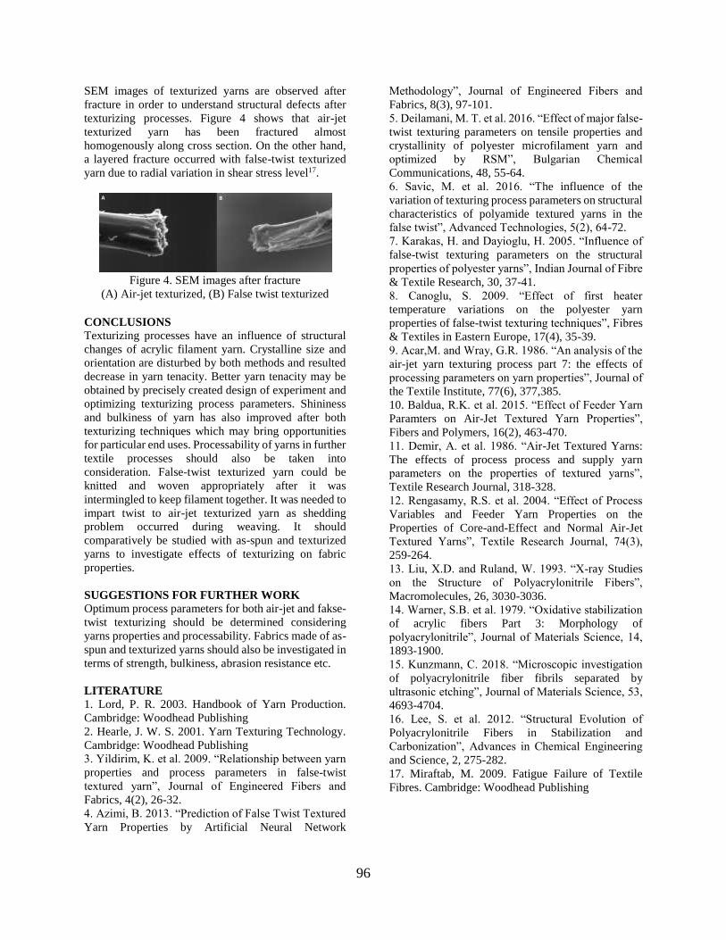
96
SEM images of texturized yarns are observed after
fracture in order to understand structural defects after
texturizing processes. Figure 4 shows that air-jet
texturized yarn has been fractured almost
homogenously along cross section. On the other hand,
a layered fracture occurred with false-twist texturized
yarn due to radial variation in shear stress level17.
Figure 4. SEM images after fracture
(A) Air-jet texturized, (B) False twist texturized
CONCLUSIONS Texturizing processes have an influence of structural
changes of acrylic filament yarn. Crystalline size and
orientation are disturbed by both methods and resulted
decrease in yarn tenacity. Better yarn tenacity may be
obtained by precisely created design of experiment and
optimizing texturizing process parameters. Shininess
and bulkiness of yarn has also improved after both
texturizing techniques which may bring opportunities
for particular end uses. Processability of yarns in further
textile processes should also be taken into
consideration. False-twist texturized yarn could be
knitted and woven appropriately after it was
intermingled to keep filament together. It was needed to
impart twist to air-jet texturized yarn as shedding
problem occurred during weaving. It should
comparatively be studied with as-spun and texturized
yarns to investigate effects of texturizing on fabric
properties.
SUGGESTIONS FOR FURTHER WORK Optimum process parameters for both air-jet and fakse-
twist texturizing should be determined considering
yarns properties and processability. Fabrics made of as-
spun and texturized yarns should also be investigated in
terms of strength, bulkiness, abrasion resistance etc.
LITERATURE 1. Lord, P. R. 2003. Handbook of Yarn Production.
Cambridge: Woodhead Publishing
2. Hearle, J. W. S. 2001. Yarn Texturing Technology.
Cambridge: Woodhead Publishing
3. Yildirim, K. et al. 2009. “Relationship between yarn
properties and process parameters in false-twist
textured yarn”, Journal of Engineered Fibers and
Fabrics, 4(2), 26-32.
4. Azimi, B. 2013. “Prediction of False Twist Textured
Yarn Properties by Artificial Neural Network
Methodology”, Journal of Engineered Fibers and
Fabrics, 8(3), 97-101.
5. Deilamani, M. T. et al. 2016. “Effect of major false-
twist texturing parameters on tensile properties and
crystallinity of polyester microfilament yarn and
optimized by RSM”, Bulgarian Chemical
Communications, 48, 55-64.
6. Savic, M. et al. 2016. “The influence of the
variation of texturing process parameters on structural
characteristics of polyamide textured yarns in the
false twist”, Advanced Technologies, 5(2), 64-72.
7. Karakas, H. and Dayioglu, H. 2005. “Influence of
false-twist texturing parameters on the structural
properties of polyester yarns”, Indian Journal of Fibre
& Textile Research, 30, 37-41.
8. Canoglu, S. 2009. “Effect of first heater
temperature variations on the polyester yarn
properties of false-twist texturing techniques”, Fibres
& Textiles in Eastern Europe, 17(4), 35-39.
9. Acar,M. and Wray, G.R. 1986. “An analysis of the
air-jet yarn texturing process part 7: the effects of
processing parameters on yarn properties”, Journal of
the Textile Institute, 77(6), 377,385.
10. Baldua, R.K. et al. 2015. “Effect of Feeder Yarn
Paramters on Air-Jet Textured Yarn Properties”,
Fibers and Polymers, 16(2), 463-470.
11. Demir, A. et al. 1986. “Air-Jet Textured Yarns:
The effects of process process and supply yarn
parameters on the properties of textured yarns”,
Textile Research Journal, 318-328.
12. Rengasamy, R.S. et al. 2004. “Effect of Process
Variables and Feeder Yarn Properties on the
Properties of Core-and-Effect and Normal Air-Jet
Textured Yarns”, Textile Research Journal, 74(3),
259-264.
13. Liu, X.D. and Ruland, W. 1993. “X-ray Studies
on the Structure of Polyacrylonitrile Fibers”,
Macromolecules, 26, 3030-3036.
14. Warner, S.B. et al. 1979. “Oxidative stabilization
of acrylic fibers Part 3: Morphology of
polyacrylonitrile”, Journal of Materials Science, 14,
1893-1900.
15. Kunzmann, C. 2018. “Microscopic investigation
of polyacrylonitrile fiber fibrils separated by
ultrasonic etching”, Journal of Materials Science, 53,
4693-4704.
16. Lee, S. et al. 2012. “Structural Evolution of
Polyacrylonitrile Fibers in Stabilization and
Carbonization”, Advances in Chemical Engineering
and Science, 2, 275-282.
17. Miraftab, M. 2009. Fatigue Failure of Textile
Fibres. Cambridge: Woodhead Publishing
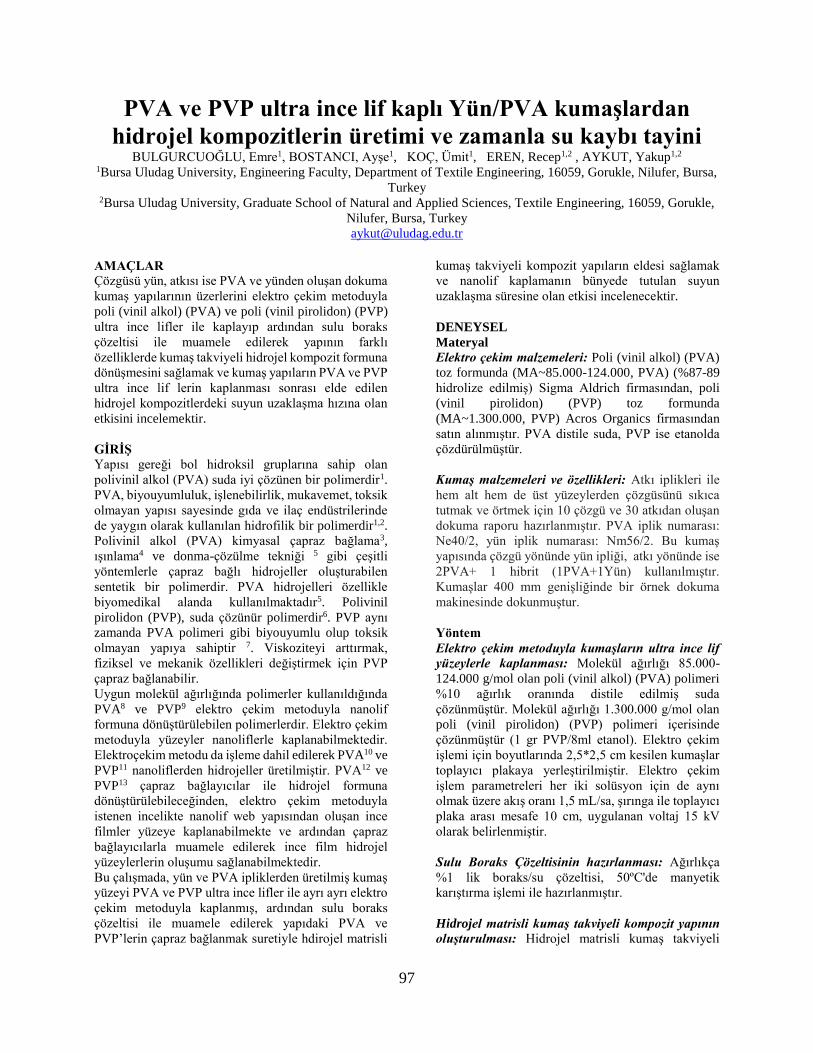
97
PVA ve PVP ultra ince lif kaplı Yün/PVA kumaşlardan
hidrojel kompozitlerin üretimi ve zamanla su kaybı tayini BULGURCUOĞLU, Emre1, BOSTANCI, Ayşe1, KOÇ, Ümit1, EREN, Recep1,2 , AYKUT, Yakup1,2
1Bursa Uludag University, Engineering Faculty, Department of Textile Engineering, 16059, Gorukle, Nilufer, Bursa,
Turkey 2Bursa Uludag University, Graduate School of Natural and Applied Sciences, Textile Engineering, 16059, Gorukle,
Nilufer, Bursa, Turkey
AMAÇLAR
Çözgüsü yün, atkısı ise PVA ve yünden oluşan dokuma
kumaş yapılarının üzerlerini elektro çekim metoduyla
poli (vinil alkol) (PVA) ve poli (vinil pirolidon) (PVP)
ultra ince lifler ile kaplayıp ardından sulu boraks
çözeltisi ile muamele edilerek yapının farklı
özelliklerde kumaş takviyeli hidrojel kompozit formuna
dönüşmesini sağlamak ve kumaş yapıların PVA ve PVP
ultra ince lif lerin kaplanması sonrası elde edilen
hidrojel kompozitlerdeki suyun uzaklaşma hızına olan
etkisini incelemektir.
GİRİŞ
Yapısı gereği bol hidroksil gruplarına sahip olan
polivinil alkol (PVA) suda iyi çözünen bir polimerdir1.
PVA, biyouyumluluk, işlenebilirlik, mukavemet, toksik
olmayan yapısı sayesinde gıda ve ilaç endüstrilerinde
de yaygın olarak kullanılan hidrofilik bir polimerdir1,2.
Polivinil alkol (PVA) kimyasal çapraz bağlama3,
ışınlama4 ve donma-çözülme tekniği 5 gibi çeşitli
yöntemlerle çapraz bağlı hidrojeller oluşturabilen
sentetik bir polimerdir. PVA hidrojelleri özellikle
biyomedikal alanda kullanılmaktadır5. Polivinil
pirolidon (PVP), suda çözünür polimerdir6. PVP aynı
zamanda PVA polimeri gibi biyouyumlu olup toksik
olmayan yapıya sahiptir 7. Viskoziteyi arttırmak,
fiziksel ve mekanik özellikleri değiştirmek için PVP
çapraz bağlanabilir.
Uygun molekül ağırlığında polimerler kullanıldığında
PVA8 ve PVP9 elektro çekim metoduyla nanolif
formuna dönüştürülebilen polimerlerdir. Elektro çekim
metoduyla yüzeyler nanoliflerle kaplanabilmektedir.
Elektroçekim metodu da işleme dahil edilerek PVA10 ve
PVP11 nanoliflerden hidrojeller üretilmiştir. PVA12 ve
PVP13 çapraz bağlayıcılar ile hidrojel formuna
dönüştürülebileceğinden, elektro çekim metoduyla
istenen incelikte nanolif web yapısından oluşan ince
filmler yüzeye kaplanabilmekte ve ardından çapraz
bağlayıcılarla muamele edilerek ince film hidrojel
yüzeylerlerin oluşumu sağlanabilmektedir.
Bu çalışmada, yün ve PVA ipliklerden üretilmiş kumaş
yüzeyi PVA ve PVP ultra ince lifler ile ayrı ayrı elektro
çekim metoduyla kaplanmış, ardından sulu boraks
çözeltisi ile muamele edilerek yapıdaki PVA ve
PVP’lerin çapraz bağlanmak suretiyle hdirojel matrisli
kumaş takviyeli kompozit yapıların eldesi sağlamak
ve nanolif kaplamanın bünyede tutulan suyun
uzaklaşma süresine olan etkisi incelenecektir.
DENEYSEL
Materyal
Elektro çekim malzemeleri: Poli (vinil alkol) (PVA)
toz formunda (MA~85.000-124.000, PVA) (%87-89
hidrolize edilmiş) Sigma Aldrich firmasından, poli
(vinil pirolidon) (PVP) toz formunda
(MA~1.300.000, PVP) Acros Organics firmasından
satın alınmıştır. PVA distile suda, PVP ise etanolda
çözdürülmüştür.
Kumaş malzemeleri ve özellikleri: Atkı iplikleri ile
hem alt hem de üst yüzeylerden çözgüsünü sıkıca
tutmak ve örtmek için 10 çözgü ve 30 atkıdan oluşan
dokuma raporu hazırlanmıştır. PVA iplik numarası:
Ne40/2, yün iplik numarası: Nm56/2. Bu kumaş
yapısında çözgü yönünde yün ipliği, atkı yönünde ise
2PVA+ 1 hibrit (1PVA+1Yün) kullanılmıştır.
Kumaşlar 400 mm genişliğinde bir örnek dokuma
makinesinde dokunmuştur.
Yöntem
Elektro çekim metoduyla kumaşların ultra ince lif
yüzeylerle kaplanması: Molekül ağırlığı 85.000-
124.000 g/mol olan poli (vinil alkol) (PVA) polimeri
%10 ağırlık oranında distile edilmiş suda
çözünmüştür. Molekül ağırlığı 1.300.000 g/mol olan
poli (vinil pirolidon) (PVP) polimeri içerisinde
çözünmüştür (1 gr PVP/8ml etanol). Elektro çekim
işlemi için boyutlarında 2,5*2,5 cm kesilen kumaşlar
toplayıcı plakaya yerleştirilmiştir. Elektro çekim
işlem parametreleri her iki solüsyon için de aynı
olmak üzere akış oranı 1,5 mL/sa, şırınga ile toplayıcı
plaka arası mesafe 10 cm, uygulanan voltaj 15 kV
olarak belirlenmiştir.
Sulu Boraks Çözeltisinin hazırlanması: Ağırlıkça
%1 lik boraks/su çözeltisi, 50ºC'de manyetik
karıştırma işlemi ile hazırlanmıştır.
Hidrojel matrisli kumaş takviyeli kompozit yapının
oluşturulması: Hidrojel matrisli kumaş takviyeli

98
kompozit yapının oluşturulması aşamasında, PVA’nın
çapraz bağlanmayla hidrojel oluşumu
gerçekleştirilmiştir. Hazırlanan %1 boraks-su çözeltisi
kumaşa dökülmüştür ve 24 saat bekletilmiştir. Yapı
suda çözündükten sonra boraks gibi fonksiyonel
moleküllerle çapraz bağlanıp suda çözünmeyen hidrojel
yapılarına dönüşmektedir.
Su kaybı testi: Numunelerin ilk önce kuru ağırlıkları
hassas terazide tartılmış ve “kuru ağırlık” olarak not
edilmiştir. Aynı numuneye belli ve sabit oranlarda pipet
yardımıyla saf su eklenir. Saf su eklendikten sonra
ortalama 15 dakika beklenir. Bu beklemenin sebebi
kumaşların bünyesine homojen bir şekilde alımını
sağlamak içindir. 15 dakika sonunda hassas terazide
tekrar ölçüm yapılmış ve “yaş ağırlık” olarak not
edilmiştir. Yaş ağırlıktan kuru ağırlık çıkarılarak
yapıdaki su miktarı tespit edilmiş ve ölçümlere devam
edilerek yüzde su kaybı grafikleri çizilmiştir.
DENEYSEL SONUÇLAR/TARTIŞMA
PVA ve PVP ultra ince lif kaplı yün/PVA kumaş
yapılarının optik mikroskop resimleri Şekil 1’de
verilmiştir. Kumaş üzerindeki PVA ultra ince lif
yüzeylerin arka taraftaki kumaşın deseni belirgin
şekilde görülmektedir (Şekil 1A ve 1B). Diğer taraftan
PVP ultra ince liflerle kaplı kumaş yüzeyinde PVP film
formunda toplanmış olup kumaşın deseninin
görünmesine engel olmuştur.
Şekil 1. (A, B) PVA ultra ince lif kaplı yün/PVA
kumaş, ve (C, D) PVP ultra ince lif kaplı yün/PVA
kumaşların optik mikroskop resimleri.
Şekil 2. PVA ultra ince lif kaplı yün/PVA kumaşların
farklı büyütme oranlarındaki SEM resimleri.
PVA ve PVP ultra ince lif kaplı yün/PVA kumaş
yapılarının SEM resimleri Şekil 2 ve Şekil 3’te
verilmiştir. Kumaş üzeriende PVA ultra ince lif
yüzey belirgin olarak Şekilde 2A’da görülmektedir.
SEM görüntü derinliği arttırıldığında yüzeydeki ultra
ince lif ler daha belirginleş altta kalan kumaş
yapısındaki kalın lifler üzerindeki PVA ultra ince
lifler net görülmektedir.
Şekil 3. PVP ultra ince lif kaplı yün/PVA
kumaşların farklı büyütme oranlarındaki SEM
resimleri.
Şekil 3’de ise kumaş yüzeyindeki PVP ultra ince lifler
SEM ile incelenmiştir. PVA ultra ince lifler kumaş
üzerinde toplandığında tam kurumamış olduğundan
ultra ince lifler birbirine temas ettiği noktalarda
birleşmiştir.

99
Şekil 4. Sulu boraks çözeltisi ile işlem görmüş: (A, B)
PVA ultra ince lif kaplı yün/PVA kumaş, ve (C,D) PVP
ultra ince lif kaplı yün kumaşların optik mikroskop
resimleri.
Sulu boraks çözeltisi ile işlem görmüş PVA ve PVP
ultra ince lif kaplı yün/PVA kumaşların optik
mikroskop resimler Şekil 4’te verilmiştir. Yapıdaki
PVA moleküllerinin jelleşmesi sonucu Şekil 1’de
kumaştan jel matris içeririnde bulunan sadece yün
ipliklerin kaldığı kumaş formuna dönmüştür.
Şekil 5. Sulu boraks çözeltisi ile işlem görmüş PVA
ultra ince lif kaplı yün/PVA kumaşların farklı büyütme
oranlarındaki SEM resimleri.
Sulu boraks çözeltisi ile işlem görmüş PVA ultra ince
lif kaplı yün/PVA kumaşların SEM resimler Şekil 5’te
verilmiştir. Jel yapıların özellikle kumaş yapısındaki
ipliklerin bağlantı noktalarında toplandığı
gözlemlenmiştir. Yün liflerinin pulçuklu yüzey yapısı
net bir şekilde görülmektedir.
Şekil 6. Sulu boraks çözeltisi ile işlem görmüş PVP
ultra ince lif kaplı yün/PVP kumaşların farklı
büyütme oranlarındaki SEM resimleri.
Sulu boraks çözeltisi ile işlem görmüş PVP ultra ince
lif kaplı yün/PVA kumaşların SEM resimler Şekil
6’da verilmiştir. Yün iplikleri ve liflerinin arasında
jelleşen veya çözündükten sonra kuruyarak kalan
PVA (kumaşın kendi yapısından gelen) ve PVP
görülmektedir. Bu kısım Şekil 5’e kıyasla Şekil 6’da
daha fazladır. Buda eğer çapraz bağlanma oranı fazla
ise yapının daha fazla su almasında, eğer az ise
yapının su ile temasında çözülerek yapıdan
uzaklaşmasına sebep olacaktır.
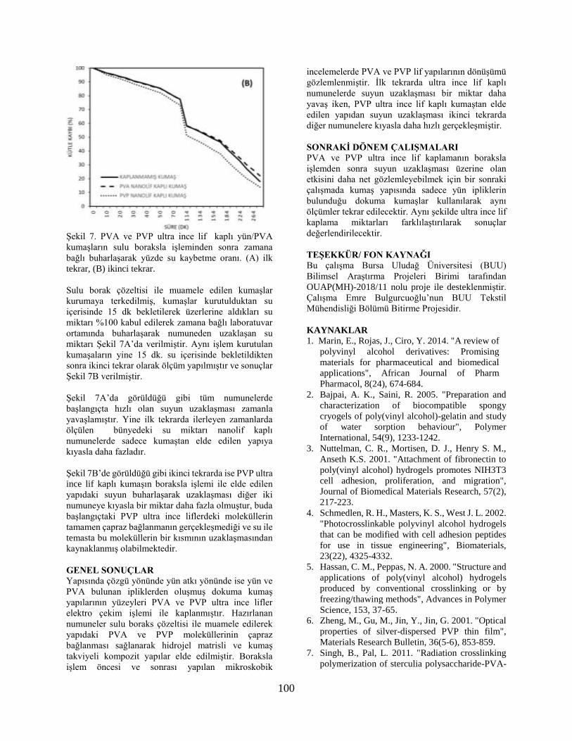
100
Şekil 7. PVA ve PVP ultra ince lif kaplı yün/PVA
kumaşların sulu boraksla işleminden sonra zamana
bağlı buharlaşarak yüzde su kaybetme oranı. (A) ilk
tekrar, (B) ikinci tekrar.
Sulu borak çözeltisi ile muamele edilen kumaşlar
kurumaya terkedilmiş, kumaşlar kurutulduktan su
içerisinde 15 dk bekletilerek üzerlerine aldıkları su
miktarı %100 kabul edilerek zamana bağlı laboratuvar
ortamında buharlaşarak numuneden uzaklaşan su
miktarı Şekil 7A’da verilmiştir. Aynı işlem kurutulan
kumaşaların yine 15 dk. su içerisinde bekletildikten
sonra ikinci tekrar olarak ölçüm yapılmıştır ve sonuçlar
Şekil 7B verilmiştir.
Şekil 7A’da görüldüğü gibi tüm numunelerde
başlangıçta hızlı olan suyun uzaklaşması zamanla
yavaşlamıştır. Yine ilk tekrarda ilerleyen zamanlarda
ölçülen bünyedeki su miktarı nanolif kaplı
numunelerde sadece kumaştan elde edilen yapıya
kıyasla daha fazladır.
Şekil 7B’de görüldüğü gibi ikinci tekrarda ise PVP ultra
ince lif kaplı kumaşın boraksla işlemi ile elde edilen
yapıdaki suyun buharlaşarak uzaklaşması diğer iki
numuneye kıyasla bir miktar daha fazla olmuştur, buda
başlangıçtaki PVP ultra ince liflerdeki moleküllerin
tamamen çapraz bağlanmanın gerçekleşmediği ve su ile
temasta bu moleküllerin bir kısmının uzaklaşmasından
kaynaklanmış olabilmektedir.
GENEL SONUÇLAR
Yapısında çözgü yönünde yün atkı yönünde ise yün ve
PVA bulunan ipliklerden oluşmuş dokuma kumaş
yapılarının yüzeyleri PVA ve PVP ultra ince lifler
elektro çekim işlemi ile kaplanmıştır. Hazırlanan
numuneler sulu boraks çözeltisi ile muamele edilerek
yapıdaki PVA ve PVP moleküllerinin çapraz
bağlanması sağlanarak hidrojel matrisli ve kumaş
takviyeli kompozit yapılar elde edilmiştir. Boraksla
işlem öncesi ve sonrası yapılan mikroskobik
incelemelerde PVA ve PVP lif yapılarının dönüşümü
gözlemlenmiştir. İlk tekrarda ultra ince lif kaplı
numunelerde suyun uzaklaşması bir miktar daha
yavaş iken, PVP ultra ince lif kaplı kumaştan elde
edilen yapıdan suyun uzaklaşması ikinci tekrarda
diğer numunelere kıyasla daha hızlı gerçekleşmiştir.
SONRAKİ DÖNEM ÇALIŞMALARI
PVA ve PVP ultra ince lif kaplamanın boraksla
işlemden sonra suyun uzaklaşması üzerine olan
etkisini daha net gözlemleyebilmek için bir sonraki
çalışmada kumaş yapısında sadece yün ipliklerin
bulunduğu dokuma kumaşlar kullanılarak aynı
ölçümler tekrar edilecektir. Aynı şekilde ultra ince lif
kaplama miktarları farklılaştırılarak sonuçlar
değerlendirilecektir.
TEŞEKKÜR/ FON KAYNAĞI
Bu çalışma Bursa Uludağ Üniversitesi (BUU)
Bilimsel Araştırma Projeleri Birimi tarafından
OUAP(MH)-2018/11 nolu proje ile desteklenmiştir.
Çalışma Emre Bulgurcuoğlu’nun BUU Tekstil
Mühendisliği Bölümü Bitirme Projesidir.
KAYNAKLAR
1. Marin, E., Rojas, J., Ciro, Y. 2014. "A review of
polyvinyl alcohol derivatives: Promising
materials for pharmaceutical and biomedical
applications", African Journal of Pharm
Pharmacol, 8(24), 674-684.
2. Bajpai, A. K., Saini, R. 2005. "Preparation and
characterization of biocompatible spongy
cryogels of poly(vinyl alcohol)-gelatin and study
of water sorption behaviour", Polymer
International, 54(9), 1233-1242.
3. Nuttelman, C. R., Mortisen, D. J., Henry S. M.,
Anseth K.S. 2001. "Attachment of fibronectin to
poly(vinyl alcohol) hydrogels promotes NIH3T3
cell adhesion, proliferation, and migration",
Journal of Biomedical Materials Research, 57(2),
217-223.
4. Schmedlen, R. H., Masters, K. S., West J. L. 2002.
"Photocrosslinkable polyvinyl alcohol hydrogels
that can be modified with cell adhesion peptides
for use in tissue engineering", Biomaterials,
23(22), 4325-4332.
5. Hassan, C. M., Peppas, N. A. 2000. "Structure and
applications of poly(vinyl alcohol) hydrogels
produced by conventional crosslinking or by
freezing/thawing methods", Advances in Polymer
Science, 153, 37-65.
6. Zheng, M., Gu, M., Jin, Y., Jin, G. 2001. "Optical
properties of silver-dispersed PVP thin film",
Materials Research Bulletin, 36(5-6), 853-859.
7. Singh, B., Pal, L. 2011. "Radiation crosslinking
polymerization of sterculia polysaccharide-PVA-
101
PVP for making hydrogel wound dressings",
International Jornal of Biological Macromoleculs,
48(3):501-10.
8. Koski, A., Yim, K., Shivkumar, S. 2004. "Effect of
molecular weight on fibrous PVA produced by
electrospinning", Materials Letters, 58(3-4), 493-
497.
9. Chuangchote, S., Sagawa, T. 2009. "Yoshikawa S.
Electrospinning of poly(vinyl pyrrolidone): Effects
of solvents on electrospinnability for the fabrication
of poly(p-phenylene vinylene) and TiO2
nanofibers", Journal of Applied Polymer Science,.
114(5), 2777-2791.
10. Cay, A., Miraftab, M. 2013. "Properties of
electrospun poly(vinyl alcohol) hydrogel nanofibers
crosslinked with 1,2,3,4-butanetetracarboxylic
acid", Journal of Applied Polymer Science, 129(6),
3140-3149.
11. Lubasova, D., Niu, H., Zhao, X., Lin, T. 2015.
"Hydrogel properties of electrospun
polyvinylpyrrolidone and
polyvinylpyrrolidone/poly(acrylic acid) blend
nanofibers", RSC Advances, 5, 54481-54487.
12. Kumar, A., Han, S. S. 2017. "PVA-based hydrogels
for tissue engineering: A review", International
Journal of Polymeric Materials and Polymeric
Biomaterials. 159-182.
13. Roy, N., Saha, N. 2012. "PVP-based hydrogels:
Synthesis, properties and applications", In:
Hydrogel synthesis, characterization, and
applications, ed. F.V. Câmara, L.J. Ferreira, Nova
Science, New York, 227–252.
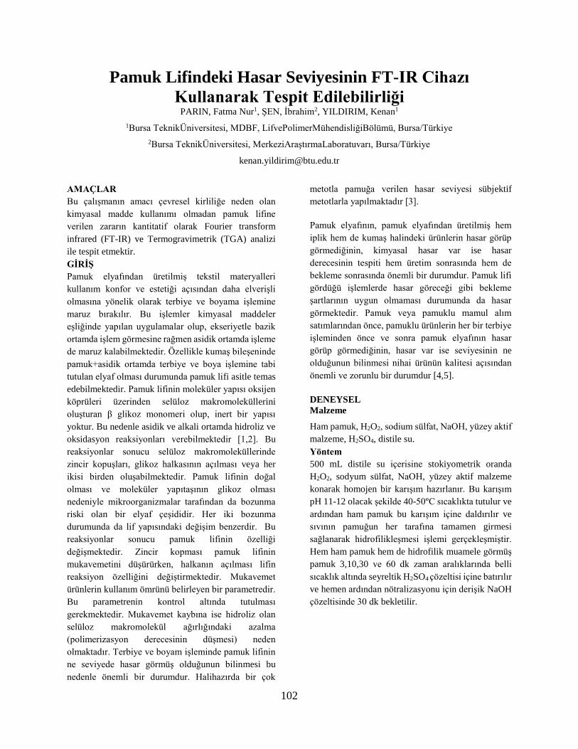
102
Pamuk Lifindeki Hasar Seviyesinin FT-IR Cihazı
Kullanarak Tespit Edilebilirliği PARIN, Fatma Nur1, ŞEN, İbrahim2, YILDIRIM, Kenan1
1Bursa TeknikÜniversitesi, MDBF, LifvePolimerMühendisliğiBölümü, Bursa/Türkiye
2Bursa TeknikÜniversitesi, MerkeziAraştırmaLaboratuvarı, Bursa/Türkiye
AMAÇLAR
Bu çalışmanın amacı çevresel kirliliğe neden olan
kimyasal madde kullanımı olmadan pamuk lifine
verilen zararın kantitatif olarak Fourier transform
infrared (FT-IR) ve Termogravimetrik (TGA) analizi
ile tespit etmektir.
GİRİŞ
Pamuk elyafından üretilmiş tekstil materyalleri
kullanım konfor ve estetiği açısından daha elverişli
olmasına yönelik olarak terbiye ve boyama işlemine
maruz bırakılır. Bu işlemler kimyasal maddeler
eşliğinde yapılan uygulamalar olup, ekseriyetle bazik
ortamda işlem görmesine rağmen asidik ortamda işleme
de maruz kalabilmektedir. Özellikle kumaş bileşeninde
pamuk+asidik ortamda terbiye ve boya işlemine tabi
tutulan elyaf olması durumunda pamuk lifi asitle temas
edebilmektedir. Pamuk lifinin moleküler yapısı oksijen
köprüleri üzerinden selüloz makromoleküllerini
oluşturan β glikoz monomeri olup, inert bir yapısı
yoktur. Bu nedenle asidik ve alkali ortamda hidroliz ve
oksidasyon reaksiyonları verebilmektedir [1,2]. Bu
reaksiyonlar sonucu selüloz makromoleküllerinde
zincir kopuşları, glikoz halkasının açılması veya her
ikisi birden oluşabilmektedir. Pamuk lifinin doğal
olması ve moleküler yapıtaşının glikoz olması
nedeniyle mikroorganizmalar tarafından da bozunma
riski olan bir elyaf çeşididir. Her iki bozunma
durumunda da lif yapısındaki değişim benzerdir. Bu
reaksiyonlar sonucu pamuk lifinin özelliği
değişmektedir. Zincir kopması pamuk lifinin
mukavemetini düşürürken, halkanın açılması lifin
reaksiyon özelliğini değiştirmektedir. Mukavemet
ürünlerin kullanım ömrünü belirleyen bir parametredir.
Bu parametrenin kontrol altında tutulması
gerekmektedir. Mukavemet kaybına ise hidroliz olan
selüloz makromolekül ağırlığındaki azalma
(polimerizasyon derecesinin düşmesi) neden
olmaktadır. Terbiye ve boyam işleminde pamuk lifinin
ne seviyede hasar görmüş olduğunun bilinmesi bu
nedenle önemli bir durumdur. Halihazırda bir çok
metotla pamuğa verilen hasar seviyesi sübjektif
metotlarla yapılmaktadır [3].
Pamuk elyafının, pamuk elyafından üretilmiş hem
iplik hem de kumaş halindeki ürünlerin hasar görüp
görmediğinin, kimyasal hasar var ise hasar
derecesinin tespiti hem üretim sonrasında hem de
bekleme sonrasında önemli bir durumdur. Pamuk lifi
gördüğü işlemlerde hasar göreceği gibi bekleme
şartlarının uygun olmaması durumunda da hasar
görmektedir. Pamuk veya pamuklu mamul alım
satımlarından önce, pamuklu ürünlerin her bir terbiye
işleminden önce ve sonra pamuk elyafının hasar
görüp görmediğinin, hasar var ise seviyesinin ne
olduğunun bilinmesi nihai ürünün kalitesi açısından
önemli ve zorunlu bir durumdur [4,5].
DENEYSEL
Malzeme
Ham pamuk, H2O2, sodium sülfat, NaOH, yüzey aktif
malzeme, H2SO4, distile su.
Yöntem
500 mL distile su içerisine stokiyometrik oranda
H2O2, sodyum sülfat, NaOH, yüzey aktif malzeme
konarak homojen bir karışım hazırlanır. Bu karışım
pH 11-12 olacak şekilde 40-50ºC sıcaklıkta tutulur ve
ardından ham pamuk bu karışım içine daldırılır ve
sıvının pamuğun her tarafına tamamen girmesi
sağlanarak hidrofilikleşmesi işlemi gerçekleşmiştir.
Hem ham pamuk hem de hidrofilik muamele görmüş
pamuk 3,10,30 ve 60 dk zaman aralıklarında belli
sıcaklık altında seyreltik H2SO4 çözeltisi içine batırılır
ve hemen ardından nötralizasyonu için derişik NaOH
çözeltisinde 30 dk bekletilir.

103
Tablo 1. Numunelerin işlem süreci.
Numune
kodu
Işlem süreci
H1 hidrofilleştirilmiş
H3 Hidrofilleştirilmiş ve 3 dk asitle muamele edilmiş
H10 Hidrofilleştirilmiş ve 10 dk asitle muamele edilmiş
H30 Hidrofilleştirilmiş ve 30 dk asitle muamele edilmiş
H60 Hidrofilleştirilmiş ve 60 dk asitle muamele edilmiş
P1 Ham pamuk
P3 3 dk asitle muamele edilmiş
P10 10 dk asitle muamele edilmiş
P30 30 dk asitle muamele edilmiş
P60 60 dk asitle muamele edilmiş
DENEYSEL SONUÇLAR/TARTIŞMA
Tüm numunelerin FTIR spektrumları (Şekil 1 ve Şekil
2) incelendiğinde selülozun karakteristik pikleri olduğu
açıkça görülmektedir. 3333cm−1'deki yayvan pik
selülozun yapısındaki ve su moleküllerinden
kaynaklanan -OH grubu ile alakalıdır [6]. 2920 ve 2850
cm-1 selülozun yapısındaki -CH2 grubunun gerilim
titreşiminden kaynaklanmaktadır. 1162, 1103, 1051,
1030 ve 999 cm-1'deki pikler ise selülozun yapısındaki
C-O-C grubunun gerilim titreşiminden
kaynaklanmaktadır [6-8]. 878 cm-1'de ham pamukta pik
olmaz iken, hidrofil hale getirilen pamuk numunesinde
pik oluştuğu ve pik şiddetinin asitle muamele
derecesine bağlı olarak arttığı görülmüştür.
Hidrofilleşen pamuk numunelerinde görülen 878 cm-
1'deki bu pik (CO3)-2‘tan kaynaklanmaktadır [9]. Asitle
muamele işleminde pamuk lifi yüzeyinde radikal
grupların oluştuğu spektrumdaki baseline düşüşünden
görülmektedir. Asitle muamele görmüş pamuk
liflerinin OH grubu pik oluşumundan sonraki
baselinede genel bir düşme olduğu görülmektedir.
Bunun ise lifte oluşan radikallerden kaynaklandığı
düşünülmektedir. 1103 cm-1’deki pik sadece asitle
işlem görmeyen hidrofilik hale gelmiş pamuk
numunesinde bulunmaktadır. H1, H3 ve H10
numunelerinde pik yükseklikleri sıralamaya göre
azalmaktadır ve H30 ve H60 numunelerinde bu pik
kaybolmuştur. 1103 cm-1’deki pik selüloz
makromolekülündeki monomerler arası köprü olan C-
O-C yapıyla ilgili olduğundan bozunma oksiselülozdan
ziyade hidroselüloz olarak oluştuğu ve zincir kopması
reaksiyonu olduğu görülmektedir [10,11]. Asitle
muamele sonrasında 1425 cm-1’de pik oluştuğu
bununda yapıya bağlanan SOx grubundan
kaynaklandığı düşünülmektedir. SOx bu pikin SOx
grubuna ait olduğuna TGA thermogramında %50 kütle
kalıntısı kalmasında ilave bir delil teşkil etmektedir.
SOx grubundan dolayı pamuk lifleri yanmazlık
özelliği kazandığından bozunma yeterli seviyede
olamamıştır.
Tablo 2. Numunelerin ısıl olayı.
kod 1.l Isıl olay 2.l Isıl olay
3.l Isıl olay % Kül
P1 215°C’de, %7.39 kütle
kaybı, su çıkışı
488°C’de, %71 kütle
kaybı, piroliz
709°C’de, %19.6 kütle
kaybı,
bozunma
0.008
P10 275°C’de, %38.68 kütle
kaybı, bozunma
- - 52.88
P60 194°C’de, %9.44 kütle
kaybı, su çıkışı
536°C'de %48.23
kütle kaybı,
piroliz
686°C'de %14.86
kütle kaybı,
bozunma
26.12
H1 178°C'de %7.20
Kütle kaybı,
su çıkışı
496°C'de %68
kütle kaybı,
piroliz
703°C'de
%19.22
kütle kaybı, bozunma
3.77
H10 341°C'de %39
kütle kaybı,
bozunma
- - 59.85
H60 279°C'de
%45.38
kütle kaybı, bozunma
- - 54.82
Bilindiği gibi SOx grupları malzemelere güç
tutuşurluk özelliği kazandırmaktadır. 878 cm-1’deki
pik yükseklikleri Tablo 3'teki gibi hesaplanmıştır.
Asitle hasar görmemiş P1 numunesi haricinde tüm
numunelerde bu pike rastlanmaktadır. Söz konusu
pik yükseklik değerleri pamuk lifinin görüdüğü
hasara bağlı olarak artmakta olup, hasar miktarı ile pik
yüksekliği arasında bir ilişki olduğu görülmüştür.
buna ilave olarak 1103 cm-1 deki pik yüksekliği ise
pamuk lifinin gördüğü hasara bağlı olarak düştüğü
görülmüştür. pik yüksekliğindeki düşüş yine hasar
miktarı ile orantılı olduğu görülmüştür. tüm asitler
SOx grubu içermediğinden hasar için bu pikin bir
anlamı yoktur. Ancak hem 1103cm-1 hem de 878 cm-
1 deki piklerdeki değişim ile pamuk hasar miktarı
korelasyonu yapılabileceği görülmüştür. Hem
hidrofilleştirilmiş hem de ham pamuğun %100
ağırlık kaybettiği ve organik yapının tamamen
bozunduğu görülmüştür (TGA thermogramı) ancak
sülfürik asitle muamele gören pamuk liflerinin %50
kütle kaybına uğradığı, yapıya bağlanmış olan SOx
gruplarının organik yapıyı oksijenli ortamda 800ºC
sıcaklıkta yanmasını engellediği görülmüştür.

104
Şekil 1. Asitle işlem görmüş ham pamuk liflerinin FTIR spektrumları.
Şekil 2. Asitle işlem görmüş hidrofilleşen pamuk
liflerinin FTIR spektrumları.
Hasar görmüş pamuk liflerinde bozunma şeklinde bir
tane ısıl olaya olurken, normal pamuk liflerinde su
çıkışı, 1. Isıl olay, organik yapının azot ortamında
pirolizi, 2. Isıl olay, oksijenli ortamda piroliz olan
kısmın bozunması 3.ısıl olay şekilde 3 farklı ısıl olayın
olduğu görülmüştür.
Tablo 3. Numunelerin verilen dalga boyundaki kantitatif
değerleri.
Numune
kodu
Frekans
(cm-1)
Pik yüksekliği
H1
1103
4.67
H3 4.42
H10 3.64
H30 -
H60 -
P1
878
-
P3 9.98
P10 28.09
P30 23.69
P60 5.12

105
Şekil 3. Pamuk liflerinin TGA termogramı.
GENEL SONUÇLAR
Pamukta oluşan hasar miktarı FT-IR analizi ile tespit
edilmektedir. 1103 cm-1 ve 878 cm-1 deki piklerden bu
hasar açıkça görülmektedir. Aynı zamanda asitle hasar
sonucunda pamuk liflerine tutunan SOx yapıya
bağlanmıştır ve yanmazlık özellik kazanabilmektedir.
SONRAKİ DÖNEM ÇALIŞMALARI
Pamuk lifindeki hasar miktarının FTIR ile tespitine
yönelik metot geliştirilmesi ve pik yükseliği ile hasar
seviyesinin optimizasyounun yapılarak yeni bir analiz
metodunun literature kavuşturulması çalışması
düşünülmektedir.
TEŞEKKÜR/BİLGİLENDİRME/FON KAYNAĞI
Ham pamuğun temin edilmesine katkı sağlayan Nazilli
Pamuk Araştırma Enstitüsü'ne teşekkür ederiz.
KAYNAKLAR
[1] Harris, M. 1954. Handbook of Textile Fibers,
Interscience Publishers, p. 226-253.
[2] Garner, W. 1966. Textile Laboratory Manual,
Vol.1, Qualitative methods, Heywood Boks, American
Elsevier, 3rd edition.
[3] Fan, Q. 2008. Fabric Chemical Testing in Fabric
Testing (ed. J. Hu), Wood Head Publishing, p.143.
[4] Gordon S. and Hsieh, Y.L. 2007. Cotton Science
and technology, Wood Head Publishing, p.6.
[5] Laurence A. 2003. ‘’Dupont, Cellulose in
lithiumchloride/N;N-dimethylacetamide, optimisation
of a dissolution method using paper substrates and
stability of the solutions’’, Polymer, 44, 4117–4126.
[6] Manasoğlu, G., Kanık, M., Yıldırım, K. 2019.
‘’Effect of fixation conditions on yellowing behavior
of cellulose powder–coated fabrics’’, JEFF, 14, 1-14.
[7] Matheus, P., Heitor, L.O.J., Ademir, J.Z. 2014.
‘’Native cellulose: structure, characterization and
thermal properties’’, Materials, 7, 6105–6119.
[8]Jiangtao, S., Dong, X., Jian, L. 2012. ‘’FTIR studies
of the changes in wood chemistry from wood forming
tissue under inclined treatment’’, Energ Proc 16, 758–
762.
[9] Andersen, F.A., Brecevic, L. 1991. ‘’Infrared
Spectra of Amorphous and Crystalline Calcium
Carbonate’’, Acta Chemica, 45,1018-1024.
[10] United States Patent Application Publication,
Pub. No.: US 2014/0225051 A1, Naskar et al. Pub.
Date: Aug. 14, 2014.
[11] Yıldırım, K. 2013. ’’Polimerik malzeme
Karekterizasyonunda İleri Metotlar’’ Ders Notu.

106
Microwave energy-based approach for carbonization and
characterization of conducting polymers covered by
simultaneously grown carbon nanotubes and metal oxide
nanowires POYRAZ, Selçuk1
1Department of Textile Engineering, Faculty of Engineering, Adıyaman University, 02040, Adıyaman/TURKEY
PURPOSE
Carbonized conducting polymer, e.g. polypyrrole
(PPy), nanostructures (nCCPs) with simultaneously
grown carbon nanotube (CNT) and metal oxide
nanowire (MONW) coverage on their surface were
manufactured, with a great potential as a building
material for advanced engineering applications such as
energy storage, via a microwave (MW) energy-based
approach.
INTRODUCTION
As a result of their uniquely blended morphological,
spectroscopic and electrochemical features,
nanostructured hybrid materials (nHMs), which contain
different types of active species with relevant functional
groups, have attracted intense research interest of
numerous research institutes from a wide variety of
science fields and industry.1-15 Since its discovery at the
beginning of 1990’s,16 CNTs, in either their single or
multi-walled forms, have been significantly
investigated as one of the most common building block
materials in affordable and high performance value
added nHM production for sensory,3,4,8,17 energy
storage,6,10,13-15,18-27 and magnetic resonance imaging
(MRI)28 applications due to their extraordinary thermal,
electrical, mechanical and electrochemical properties.
Nanostructured metals15 or MOs7,10 made up of
Fe2O3,14,28-30 Fe3O4,2 ZnO,6 MnO2,3,8,31 and TiO21,14
have been commonly utilized, by means of filling6 or
attaching via spontaneous self-assembly,5 along with
CNTs in order to both enhance and diversify their above
mentioned inherent properties and to optimize their use
in nHM production.26 As one of the most well-known
and well-studied members of CP family, owing to its
advantageous properties such as facile and low-cost
synthesis at ambient conditions with high yield,
relatively high electrical conductivity, long-term
environmental stability, and high electrochemical
performance, PPy is chosen as the active host material
to prepare the targeted nHM together with the
simultaneously grown CNT and Fe2O3 NW guest
materials on its carbonized surface via MW energy-
based approach.1,2,6,7,12,13,22,32-40 Thus, the targeted
nHMs’ preparation in 3D composite form, via MW
energy-based approach along with the utilization of
nCCP as the host and the simultaneously grown CNTs
and MONWs as the “surface decoration” guest, would
result in combination of both the advantageous
nanostructured material design and unique
electrochemical properties of all the individual
components in one structure.1,3-15,26,29,31,41,42 With that,
in current study, a well-established, in-situ
polymerization/coating method and a simple and
straightforward ex-situ MW energy-based
carbonization approach, i.e. PopTube, are
systematically combined to prepare the targeted novel
nHM composites.
EXPERIMENTAL
Material
Following chemicals and reagents, including
ammonium peroxydisulfate (APS, (NH4)2S2O8, 98%
min.), ferrocene (99%), acetone, and pyrrole (98%),
were all purchased from Alfa Aesar and used for the
synthesis reactions. Iron pentacarbonyl (Fe(CO)5,
99.5% and 99%-Fe) was purchased from Strem
Chemicals and used for MW energy-based nHM
preparation.
Method
In order to obtain the targeted nHM samples; 50 mg
of PPy/ferrocene powder was placed in a glass vial
and soaked with 0.1 mL of Fe(CO)5 until its surface
became completely wet. After the partial evaporation
of the liquid phase, the damp sample was placed into
a standard kitchen MW oven (Panasonic Inverter,
NN-SN936B) chamber for the quick heating process
as shown in Figure 1.
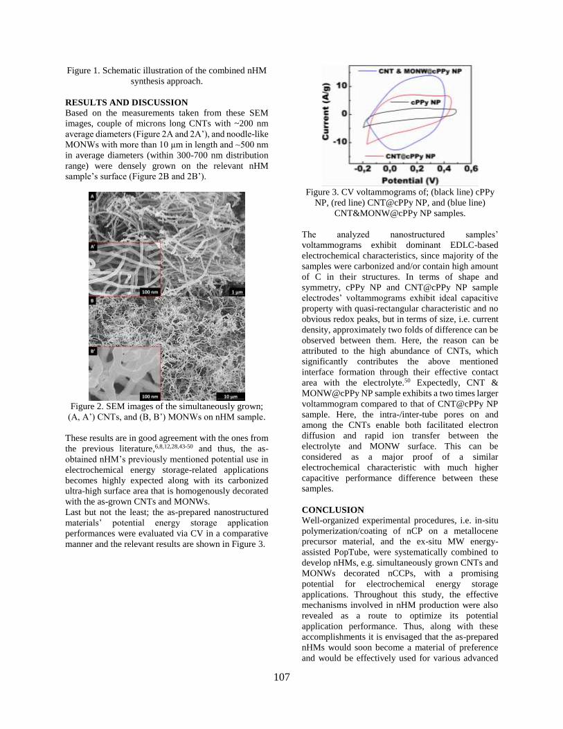
107
Figure 1. Schematic illustration of the combined nHM
synthesis approach.
RESULTS AND DISCUSSION
Based on the measurements taken from these SEM
images, couple of microns long CNTs with ~200 nm
average diameters (Figure 2A and 2A’), and noodle-like
MONWs with more than 10 µm in length and ~500 nm
in average diameters (within 300-700 nm distribution
range) were densely grown on the relevant nHM
sample’s surface (Figure 2B and 2B’).
Figure 2. SEM images of the simultaneously grown;
(A, A’) CNTs, and (B, B’) MONWs on nHM sample.
These results are in good agreement with the ones from
the previous literature,6,8,12,28,43-50 and thus, the as-
obtained nHM’s previously mentioned potential use in
electrochemical energy storage-related applications
becomes highly expected along with its carbonized
ultra-high surface area that is homogenously decorated
with the as-grown CNTs and MONWs.
Last but not the least; the as-prepared nanostructured
materials’ potential energy storage application
performances were evaluated via CV in a comparative
manner and the relevant results are shown in Figure 3.
Figure 3. CV voltammograms of; (black line) cPPy
NP, (red line) CNT@cPPy NP, and (blue line)
CNT&MONW@cPPy NP samples.
The analyzed nanostructured samples’
voltammograms exhibit dominant EDLC-based
electrochemical characteristics, since majority of the
samples were carbonized and/or contain high amount
of C in their structures. In terms of shape and
symmetry, cPPy NP and CNT@cPPy NP sample
electrodes’ voltammograms exhibit ideal capacitive
property with quasi-rectangular characteristic and no
obvious redox peaks, but in terms of size, i.e. current
density, approximately two folds of difference can be
observed between them. Here, the reason can be
attributed to the high abundance of CNTs, which
significantly contributes the above mentioned
interface formation through their effective contact
area with the electrolyte.50 Expectedly, CNT &
MONW@cPPy NP sample exhibits a two times larger
voltammogram compared to that of CNT@cPPy NP
sample. Here, the intra-/inter-tube pores on and
among the CNTs enable both facilitated electron
diffusion and rapid ion transfer between the
electrolyte and MONW surface. This can be
considered as a major proof of a similar
electrochemical characteristic with much higher
capacitive performance difference between these
samples.
CONCLUSION
Well-organized experimental procedures, i.e. in-situ
polymerization/coating of nCP on a metallocene
precursor material, and the ex-situ MW energy-
assisted PopTube, were systematically combined to
develop nHMs, e.g. simultaneously grown CNTs and
MONWs decorated nCCPs, with a promising
potential for electrochemical energy storage
applications. Throughout this study, the effective
mechanisms involved in nHM production were also
revealed as a route to optimize its potential
application performance. Thus, along with these
accomplishments it is envisaged that the as-prepared
nHMs would soon become a material of preference
and would be effectively used for various advanced

108
applications such as electrochemical energy storage,
MRI imaging, water treatment and so on.
REFERENCES
Çelik, E. J. 1986. “Crystallinity of PET fibers”, Textile
Research Journal, 104, 269-274.
1. de Oliveira H. P. 2015. “Synthesis and dielectric
characterization of multiwalled carbon
nanotubes/polypyrrole/titanium dioxide composites”,
Fullerenes Nanotubes Carbon Nanostructures, 23 (4),
339-345.
2. Ghashghaei, E., Kheirjou, S., Asgari, S, Kazerooni,
H. 2018. “Nanostructured ternary composites of
PPy/CNT/NiFe2O4 and PPy/CNT/CoFe2O4:
Delineating and improving microwave absorption”,
Comptes Rendus Chimie, 21 (9), 862-871.
3. Hou, Y., Cheng, Y. W., Hobson, T., Liu, J. 2010.
“Design and synthesis of hierarchical MnO2
nanospheres/carbon nanotubes/conducting polymer
ternary composite for high performance
electrochemical electrodes”, Nano Letters, 10 (7),
2727-2733.
4. Hu, Y., Guo, C. 2011. Carbon Nanotubes - Growth
and Applications. Rijeca, CROATIA: INTECH.
5. Li, J., Tang, S. B., Lu, L., Zeng, H. C. 2007.
“Preparation of nanocomposites of metals, metal
oxides, and carbon nanotubes via self-assembly”,
Journal of the American Chemical Society, 129 (30),
9401-9409.
6. Liu, Y., Zhang, X. Y., Poyraz, S., Zhang, C., Xin, J.
H. 2018. “One-step synthesis of multifunctional zinc-
iron-oxide hybrid carbon nanowires by chemical fusion
for supercapacitors and interfacial water marbles”,
ChemNanoMat, 4 (6), 546-556.
7. Lokhande, V. C., Lokhande, A. C., Lokhande, C. D.,
Kim, J. H., Ji, T. 2016. “Supercapacitive composite
metal oxide electrodes formed with carbon, metal
oxides and conducting polymers”, Journal of Alloys
and Compounds, 682, 381-403.
8. Luo, Y., Wang, K., Luo, S., Zhao, F., Wu, H., Jiang,
K., Li, Q., Fan, S., Wang, J. 2018. “Three-dimensional
carbon nanotube/transition-metal oxide sponges as
composite electrodes with enhanced electrochemical
performance”, ACS Applied Nano Materials, 1, 2997-
3005.
9. Mao, X. W., Simeon, F., Achilleos, D. S., Rutledge,
G. C., Hatton, T. A. 2013. “Metallocene/carbon hybrids
prepared by a solution process for supercapacitor
applications”, Journal of Materials Chemistry A, 1 (42),
13120-13127.
10. Mazloumi, M., Shadmehr, S., Rangom, Y., Nazar,
L. F., Tang, X. W. 2013. “Fabrication of three-
dimensional carbon nanotube and metal oxide hybrid
mesoporous architectures”, ACS Nano, 7 (5), 4281-
4288.
11. Motshekga, S. C., Pillai, S. K., Ray, S. S., Jalama,
K., Krause, R. W. M. 2012. “Recent trends in the
microwave-assisted synthesis of metal oxide
nanoparticles supported on carbon nanotubes and
their applications”, Journal of Nanomaterials,
691503, 1-15.
12. Poyraz, S., Cook, J., Liu, Z., Zhang, L., Nautiyal,
A., Hohmann, B., Klamt, S., Zhang, X. Y. 2018.
“Microwave energy-based manufacturing of hollow
carbon nanospheres decorated with carbon nanotubes
or metal oxide nanowires”, Journal of Materials
Science, 53 (17), 12178-12189.
13. Xiong, P., Zhu, J. W., Wang, X. 2015. “Recent
advances on multi-component hybrid nanostructures
for electrochemical capacitors”, Journal of Power
Sources, 294, 31-50.
14. Zheng, W., Zhang, P. G., Chen, J., Tian, W. B.,
Zhang, Y. M., Sun, Z. M. 2019. “Microwave-assisted
synthesis of three-dimensional MXene derived metal
oxide/carbon nanotube/iron hybrids for enhanced
lithium-ions storage”, Journal of Electroanalytical
Chemistry, 835, 205-211.
15. Zheng, W., Zhang, P. G., Yang, L., Chen, J., Tian,
W. B., Zhang, Y. M., Sun, Z. M. 2018. “A fast
approach to the synthesis of MO/CNT/Fe hybrid
nanostructures built on MXene for enhanced Li-ion
uptake”, Ceramics International, 44 (18), 22456-
22461.
16. Iijima, S. 1991. “Helical microtubules of graphitic
carbon”, Nature, 354 (6348), 56-58.
17. Lota, G., Fic, K., Frackowiak, E. 2011. “Carbon
nanotubes and their composites in electrochemical
applications”, Energy and Environmental Science, 4
(5), 1592-1605.
18. Bose, S., Kuila, T., Mishra, A. K., Rajasekar, R.,
Kim, N. H., Lee, J. H. 2012. “Carbon-based
nanostructured materials and their composites as
supercapacitor electrodes”, Journal of Materials
Chemistry, 22 (3), 767-784.
19. Chen, C., Fan, Y. Q., Gu, J. H., Wu, L. M.,
Passerini, S., Mai, L. Q. 2018. “One-dimensional
nanomaterials for energy storage”, Journal of Physics
D: Applied Physics, 51 (11).
20. De Adhikari, A., Oraon, R., Tiwari, S. K., Saren,
P., Maity, C. K., Lee, J. H., Kim, N. H., Nayak, G. C.
2018. “Zn-doped SnO2 nano-urchin-enriched 3D
carbonaceous framework for supercapacitor
application”, New Journal of Chemistry, 42 (2), 955-
963.
21. Jiang, L. B., Yuan, X. Z., Liang, J., Zhang, J.,
Wang, H., Zeng, G. M. 2016. “Nanostructured core-
shell electrode materials for electrochemical
capacitors”, Journal of Power Sources, 331, 408-425.
22. Meng, Q. F., Cai, K. F., Chen, Y. X., Chen, L. D.
2017. “Research progress on conducting polymer

109
based supercapacitor electrode materials”, Nano
Energy, 36, 268-285.
23. Syarif, N., Ivandini, T. A., Wibowo, W. 2012.
“Direct synthesis carbon/metal oxide composites for
electrochemical capacitors electrode”, International
Transaction Journal of Engineering, Management, &
Applied Sciences & Technologies, 3 (1), 21-34.
24. Wang, X. M., Wang, W. W., Zhu, Z. H., Yan, C.,
Zhang, Q. T. 2017. “Metal oxide-embedded porous
carbon nanoparticles as high-performance anode
materials for lithium ion batteries”, Ionics, 23 (12),
3255-3263.
25. Xia, C., Chen, W., Wang, X. B., Hedhili, M. N.,
Wei, N. N., Alshareef, H. N. 2015. “Highly stable
supercapacitors with conducting polymer core-shell
electrodes for energy storage applications”. Advanced
Energy Materials, 5 (8), 1401805-1401813.
26. Yu, G., Xie, X., Pan, L., Bao, Z., Cui, Y. 2012.
“Hybrid nanostructured materials for high-performance
electrochemical capacitors”, Nano Energy, 2, 213-234.
27. Zhang, L. L., Zhao, X. S. 2009. “Carbon-based
materials as supercapacitor electrodes”, Chemical
Society Reviews, 38 (9), 2520-2531.
28. Xie, H., Poyraz, S., Thu, M., Liu, Y., Snyder, E. Y.,
Smith, J. W., Zhang, X. Y. 2014. “Microwave-assisted
fabrication of carbon nanotubes decorated polymeric
nano-medical platforms for simultaneous drug delivery
and magnetic resonance imaging”, RSC Advances, 4
(11), 5649-5652.
29. Zhao, Y., Li, J. X., Wu, C. X., Guan, L. H. 2011. “A
general strategy for synthesis of metal oxide
nanoparticles attached on carbon nanomaterials”,
Nanoscale Research Letters, 6, 71-75.
30. Zhang, G. D., Shi, Y. H., Wang, H. R., Jiang, L. L.,
Yu, X. D., Jing, S. Y., Xing, S. X., Tsiakaras, P. 2019.
“A facile route to achieve ultrafine Fe2O3 nanorods
anchored on graphene oxide for application in lithium-
ion battery”, Journal of Power Sources, 416, 118-124.
31. Yan, J., Fan, Z. J., Wei, T., Cheng, J., Shao, B.,
Wang, K., Song, L. P., Zhang, M. L. 2009. “Carbon
nanotube/MnO2 composites synthesized by
microwave-assisted method for supercapacitors with
high power and energy densities”, Journal of Power
Sources, 194 (2), 1202-1207.
32. Liu, Z., Zhang, L., Poyraz, S., Smith, J., Kushvaha,
V. Tippur, H., Zhang, X. Y. 2014. “An ultrafast
microwave approach towards multicomponent and
multi-dimensional nanomaterials”, RSC Advances, 4
(18), 9308-9313.
33. Fong, K. D., Wang, T. S., Smoukov, S. K. 2017.
“Multidimensional performance optimization of
conducting polymer-based supercapacitor electrodes”,
Sustainable Energy Fuels, 1 (9), 1857-1874.
34. Liu, Z., Liu, Y., Poyraz, S., Zhang, X. Y. 2011.
“Green-nano approach to nanostructured polypyrrole”,
Chemical Communications, 47 (15), 4421-4423.
35. Liu, Z., Zhang, X. Y., Poyraz, S., Surwade, S. P.,
Manohar S. K. 2010. “Oxidative template for
conducting polymer nanoclips”, Journal of the
American Chemical Society, 132 (38), 13158-13159.
36. Lu, X. F., Zhang, W. J., Wang, C., Wen, T. C.,
Wei, Y. 2011. “One-dimensional conducting polymer
nanocomposites: Synthesis, properties and
applications”, Progress in Polymer Science, 36 (5),
671-712.
37. Poyraz, S., Flogel, M., Liu, Z., Zhang, X. Y. 2017.
“Microwave energy assisted carbonization of
nanostructured conducting polymers for their
potential use in energy storage applications”, Pure and
Applied Chemistry, 89 (1), 173-182.
38. Raza, W., Ali, F. Z., Raza, N., Luo, Y. W., Kim,
K. H., Yang, J. H., Kumar, S., Mehmood, A., Kwon,
E. E. 2018. “Recent advancements in supercapacitor
technology”, Nano Energy, 52, 441-473.
39. Reddy, K. R., Sin, B. C., Ryu, K. S., Kim, J. C.,
Chung, H., Lee, Y. 2009. “Conducting polymer
functionalized multi-walled carbon nanotubes with
noble metal nanoparticles: Synthesis, morphological
characteristics and electrical properties”, Synthetic
Metals, 159 (7-8), 595-603.
40. Zhang, L., Du, W. Y., Nautiyal, A., Liu, Z.,
Zhang, X. Y. 2018. “Recent progress on
nanostructured conducting polymers and composites:
synthesis, application and future aspects”, Science
China Materials, 61 (3), 303-352.
41. Lakshmi, A., Gracelin, D. L., Vigneshwari, M.,
Karpagavinayagam, P., Veeraputhiran, V. C. V. 2015.
“Microwave synthesis and characterization of
multiwalled carbon nanotubes (MWCNT) and metal
oxide doped MWCNT”, Journal of Nanoscience and
Technology, 1, 19-22.
42. Lin, Y., Baggett, D. W., Kim, J. W., Siochi, E. J.,
Connell, J. W. 2011. “Instantaneous formation of
metal and metal oxide nanoparticles on carbon
nanotubes and graphene via solvent-free microwave
heating”, ACS Applied Materials and Interfaces, 3
(5), 1652-1664.
43. Liu, Y., Guo, N., Yin, P., Zhang, C. 2019. “Facile
growth of carbon nanotubes by microwave ovens:
The emerging application of the highly efficient
domestic plasma reactors”, Nanoscale Advances, 1,
4546-4559.
44. Liu, Z., Wang, J. L., Kushvaha, V., Poyraz, S.,
Tippur, H., Park, S., Kim, M., Liu, Y., Bar, J., Chen,
H., Zhang. X. Y. 2011. “Poptube approach for
ultrafast carbon nanotube growth”, Chemical
Communications, 47 (35), 9912-9914.
45. Liu, Z., Zhang, L., Poyraz, S., Smith, J.,
Kushvaha, V., Tippur, H., Zhang, X. Y. 2014. “An
ultrafast microwave approach towards
multicomponent and multi-dimensional
nanomaterials”, RSC Advances, 4 (18), 9308-9313.

110
46. Poyraz, S., Liu, Z., Liu, Y., Zhang, X. Y. 2013.
“Devulcanization of scrap ground tire rubber and
successive carbon nanotube growth by microwave
irradiation”, Current Organic Chemistry, 17 (20), 2243-
2248.
47. Schwenke, A. M., Hoeppener, S., Schubert, U. S.
2015. “Synthesis and modification of carbon
nanomaterials utilizing microwave heating”, Advanced
Materials, 27 (28), 4113-4141.
48. Zhang, X. Y., Liu, Z. 2012. “Recent advances in
microwave initiated synthesis of nanocarbon
materials”, Nanoscale, 4 (3), 707-714.
49. Poyraz, S., Zhang, L., Schroder, A., Zhang, X. Y.
2015. “Ultrafast microwave welding/reinforcing
approach at the interface of thermoplastic materials”,
ACS Applied Materials and Interfaces, 7 (40), 22469-
22477.
50. Liu, Z., Chen, L., Zhang, L., Poyraz, S., Guo, Z. H.,
Zhang, X. Y., Zhu, J. H. 2014. “Ultrafast Cr(VI)
removal from polluted water by microwave synthesized
iron oxide submicron wires”, Chemical
Communications, 50 (59), 8036-8039.
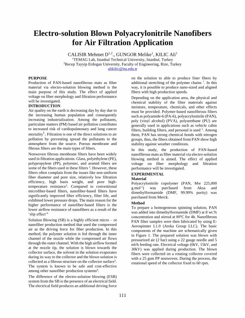
111
Electro-solution Blown Polyacrylonitrile Nanofibers
for Air Filtration Application
CALISIR Mehmet D1,2., GUNGOR Melike1, KILIC Ali1 1TEMAG Lab, Istanbul Technical University, Istanbul, Turkey
2Recep Tayyip Erdogan University, Faculty of Engineering, Rize, Turkey
PURPOSE
Production of PAN-based nanofibrous mats as filter
material via electro-solution blowing method is the
main purpose of this study. The effect of applied
voltage on fiber morphology and filtration performance
will be investigated.
INTRODUCTION
Air quality on the earth is decreasing day by day due to
the increasing human population and consequently
increasing industrialization. Among the pollutants,
particulate matters (PM) based air pollution contributes
to increased risk of cardiopulmonary and lung cancer
mortality1. Filtration is one of the direct solutions to air
pollution by preventing spread the pollutants to the
atmosphere from the source. Porous membrane and
fibrous filters are the main types of filters.
Nonwoven fibrous membrane filters have been widely
used in filtration applications. Glass, polyethylene (PE),
polypropylene (PP), polyester, and aramid fibers are
some of the fibers used in these filters 2. However, these
filters often complain from the issues like non-uniform
fiber diameter and pore size, relatively low filtration
efficiency, high basis weight, and poor high-
temperature resistance3. Compared to conventional
microfiber-based filters, nanofiber-based filters have
significantly improved filter efficiency, filter life, and
exhibited lower pressure drops. The main reason for the
higher performance of nanofiber-based filters is the
lower airflow resistance of nanofibers as a result of the
‘slip effect’4
Solution Blowing (SB) is a highly efficient micro – or
nanofiber production method that used the compressed
air as the driving force for fiber production. In this
method, the polymer solution is fed through the inner
channel of the nozzle while the compressed air flows
through the outer channel. With the high airflow formed
at the nozzle tip, the solution is blown towards the
collector surface, the solvent in the solution evaporates
during its way to the collector and the blown solution is
collected as a fibrous structure on the collector surface5.
The system is known to be safe and cost-effective
among other nanofiber production systems6.
The difference of the electro-solution blowing (ESB)
system from the SB is the presence of an electrical field.
The electrical field produces an additional driving force
on the solution to able to produce finer fibers by
additional stretching of the polymer chains 7. In this
way, it is possible to produce nano-sized and aligned
fibers with high production speeds.
Depending on the application area, the physical and
chemical stability of the filter materials against
moisture, temperature, chemicals, and other effects
must be provided. Polymer-based nanofibrous filters
such as polyamide-6 (PA-6), polyacrylonitrile (PAN),
poly (vinyl alcohol) (PVA), polyurethane (PU) are
generally used in applications such as vehicle cabin
filters, building filters, and personal is used 2. Among
them, PAN has strong chemical bonds with nitrogen
groups, thus, the fibers obtained from PAN show high
stability against weather conditions.
In this study, the production of PAN-based
nanofibrous mats as filter material via electro-solution
blowing method is aimed. The effect of applied
voltage on fiber morphology and filtration
performance will be investigated.
EXPERIMENTAL
Material
Polyacrylonitrile copolymer (PAN, Mw 225,000
g.mol-1) was purchased from Aksa and
dimethylformamide (DMF, 99.99% purity) was
purchased from Merck.
Method
To prepare a homogeneous spinning solution, PAN
was added into dimethylformamide (DMF) at 8 wt.%
concentration and stirred at 80ºC for 4h. Nanofibrous
PAN filter samples were then fabricated by using E-
Aerospinner L1.0 (Areka Group LLC). The basic
components of the machine are schematically given
in Figure 1. The prepared solution was blown with
pressurized air (2 bar) using a 22 gauge needle and 5
ml/h feeding rate. Electrical voltage (0kV, 15kV, and
30kV) was applied during production. The blown
fibers were collected on a rotating collector covered
with a 25 gsm PP nonwoven. During the process, the
rotational speed of the collector fixed to 60 rpm.
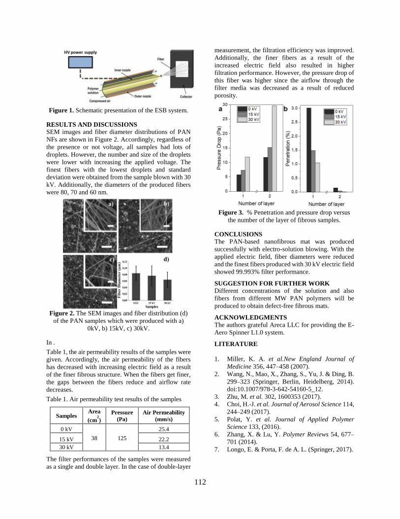
112
Figure 1. Schematic presentation of the ESB system.
RESULTS AND DISCUSSIONS
SEM images and fiber diameter distributions of PAN
NFs are shown in Figure 2. Accordingly, regardless of
the presence or not voltage, all samples had lots of
droplets. However, the number and size of the droplets
were lower with increasing the applied voltage. The
finest fibers with the lowest droplets and standard
deviation were obtained from the sample blown with 30
kV. Additionally, the diameters of the produced fibers
were 80, 70 and 60 nm.
Figure 2. The SEM images and fiber distribution (d)
of the PAN samples which were produced with a)
0kV, b) 15kV, c) 30kV.
In .
Table 1, the air permeability results of the samples were
given. Accordingly, the air permeability of the fibers
has decreased with increasing electric field as a result
of the finer fibrous structure. When the fibers get finer,
the gaps between the fibers reduce and airflow rate
decreases.
Table 1. Air permeability test results of the samples
Samples Area
(cm2)
Pressure
(Pa) Air Permeability
(mm/s)
0 kV
38 125
25.4
15 kV 22.2
30 kV 13.4
The filter performances of the samples were measured
as a single and double layer. In the case of double-layer
measurement, the filtration efficiency was improved.
Additionally, the finer fibers as a result of the
increased electric field also resulted in higher
filtration performance. However, the pressure drop of
this fiber was higher since the airflow through the
filter media was decreased as a result of reduced
porosity.
Figure 3. % Penetration and pressure drop versus
the number of the layer of fibrous samples.
CONCLUSIONS
The PAN-based nanofibrous mat was produced
successfully with electro-solution blowing. With the
applied electric field, fiber diameters were reduced
and the finest fibers produced with 30 kV electric field
showed 99.993% filter performance.
SUGGESTION FOR FURTHER WORK
Different concentrations of the solution and also
fibers from different MW PAN polymers will be
produced to obtain defect-free fibrous mats.
ACKNOWLEDGMENTS
The authors grateful Areca LLC for providing the E-
Aero Spinner L1.0 system.
LITERATURE
1. Miller, K. A. et al.New England Journal of
Medicine 356, 447–458 (2007).
2. Wang, N., Mao, X., Zhang, S., Yu, J. & Ding, B.
299–323 (Springer, Berlin, Heidelberg, 2014).
doi:10.1007/978-3-642-54160-5_12.
3. Zhu, M. et al. 302, 1600353 (2017).
4. Choi, H.-J. et al. Journal of Aerosol Science 114,
244–249 (2017).
5. Polat, Y. et al. Journal of Applied Polymer
Science 133, (2016).
6. Zhang, X. & Lu, Y. Polymer Reviews 54, 677–
701 (2014).
7. Longo, E. & Porta, F. de A. L. (Springer, 2017).
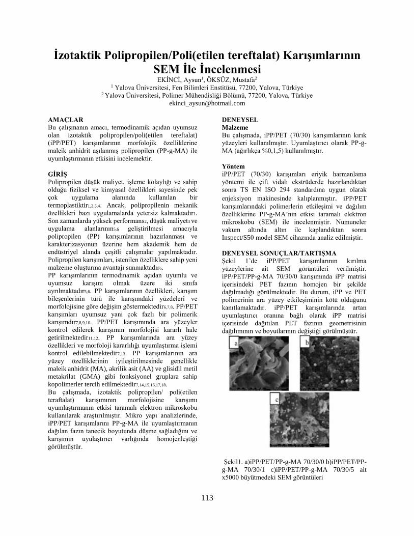
113
İzotaktik Polipropilen/Poli(etilen tereftalat) Karışımlarının
SEM İle İncelenmesi EKİNCİ, Aysun1, ÖKSÜZ, Mustafa2
1 Yalova Üniversitesi, Fen Bilimleri Enstitüsü, 77200, Yalova, Türkiye 2 Yalova Üniversitesi, Polimer Mühendisliği Bölümü, 77200, Yalova, Türkiye
AMAÇLAR Bu çalışmanın amacı, termodinamik açıdan uyumsuz
olan izotaktik polipropilen/poli(etilen tereftalat)
(iPP/PET) karışımlarının morfolojik özelliklerine
maleik anhidrit aşılanmış polipropilen (PP-g-MA) ile
uyumlaştırmanın etkisini incelemektir.
GİRİŞ Polipropilen düşük maliyet, işleme kolaylığı ve sahip
olduğu fiziksel ve kimyasal özellikleri sayesinde pek
çok uygulama alanında kullanılan bir
termoplastiktir1,2,3,4. Ancak, polipropilenin mekanik
özellikleri bazı uygulamalarda yetersiz kalmaktadır1.
Son zamanlarda yüksek performans2, düşük maliyet3 ve
uygulama alanlarının5,6 geliştirilmesi amacıyla
polipropilen (PP) karışımlarının hazırlanması ve
karakterizasyonun üzerine hem akademik hem de
endüstriyel alanda çeşitli çalışmalar yapılmaktadır.
Polipropilen karışımları, istenilen özelliklere sahip yeni
malzeme oluşturma avantajı sunmaktadır6.
PP karışımlarının termodinamik açıdan uyumlu ve
uyumsuz karışım olmak üzere iki sınıfa
ayrılmaktadır5,6. PP karışımlarının özellikleri, karışım
bileşenlerinin türü ile karışımdaki yüzdeleri ve
morfolojisine göre değişim göstermektedir6,7,8. PP/PET
karışımları uyumsuz yani çok fazlı bir polimerik
karışımdır7,8,9,10. PP/PET karışımında ara yüzeyler
kontrol edilerek karışımın morfolojisi kararlı hale
getirilmektedir11,12. PP karışımlarında ara yüzey
özellikleri ve morfoloji kararlılığı uyumlaştırma işlemi
kontrol edilebilmektedir7,13. PP karışımlarının ara
yüzey özelliklerinin iyileştirilmesinde genellikle
maleik anhidrit (MA), akrilik asit (AA) ve glisidil metil
metakrilat (GMA) gibi fonksiyonel gruplara sahip
kopolimerler tercih edilmektedir7,14,15,16,17,18.
Bu çalışmada, izotaktik polipropilen/ poli(etilen
teraftalat) karışımının morfolojisine karışımı
uyumlaştırmanın etkisi taramalı elektron mikroskobu
kullanılarak araştırılmıştır. Mikro yapı analizlerinde,
iPP/PET karışımlarını PP-g-MA ile uyumlaştırmanın
dağılan fazın tanecik boyutunda düşme sağladığını ve
karışımın uyulaştırıcı varlığında homojenleştiği
görülmüştür.
DENEYSEL
Malzeme Bu çalışmada, iPP/PET (70/30) karışımlarının kırık
yüzeyleri kullanılmıştır. Uyumlaştırıcı olarak PP-g-
MA (ağırlıkça %0,1,5) kullanılmıştır.
Yöntem iPP/PET (70/30) karışımları eriyik harmanlama
yöntemi ile çift vidalı ekstrüderde hazırlandıktan
sonra TS EN ISO 294 standardına uygun olarak
enjeksiyon makinesinde kalıplanmıştır. iPP/PET
karışımlarındaki polimerlerin etkileşimi ve dağılım
özelliklerine PP-g-MA’nın etkisi taramalı elektron
mikroskobu (SEM) ile incelenmiştir. Numuneler
vakum altında altın ile kaplandıktan sonra
Inspect/S50 model SEM cihazında analiz edilmiştir.
DENEYSEL SONUÇLAR/TARTIŞMA Şekil 1’de iPP/PET karışımlarının kırılma
yüzeylerine ait SEM görüntüleri verilmiştir.
iPP/PET/PP-g-MA 70/30/0 karışımında iPP matrisi
içerisindeki PET fazının homojen bir şekilde
dağılmadığı görülmektedir. Bu durum, iPP ve PET
polimerinin ara yüzey etkileşiminin kötü olduğunu
kanıtlamaktadır. iPP/PET karışımlarında artan
uyumlaştırıcı oranına bağlı olarak iPP matrisi
içerisinde dağıtılan PET fazının geometrisinin
dağılımının ve boyutlarının değiştiği görülmüştür.
Şekil1. a)iPP/PET/PP-g-MA 70/30/0 b)iPP/PET/PP-
g-MA 70/30/1 c)iPP/PET/PP-g-MA 70/30/5 ait
x5000 büyütmedeki SEM görüntüleri

114
Uyumlaştırıcı oranındaki artış PET’in daha homojen
dağılmasını sağlayarak iPP matrisi ile PET fazının ara
yüzey etkileşimini artırmıştır (Şekil 2).
Şekil 2. a) iPP/PET/PP-g-MA 70/30/1 b) iPP/PET/PP-
g-MA 70/30/5 ait x50000 büyütmedeki SEM
görüntüleri
GENEL SONUÇLAR
Bu çalışmada iPP/PET (70/30) karışımlarının
morfolojik özelliklerine uyumlaştırmanın etkisi SEM
ile incelenmiştir. Artan uyumlaştırıcı oranına bağlı
olarak, iPP’nin PET fazının ara yüzey özelliklerinin
iyileştiği görülmektedir. Bu durumun PP-g-MA’nın
fonksiyonel uç grubunun PET’in fonksiyonel uç
gruplarının etkileşiminin kanıtıdır. Hazırlanan
karışımların mikro yapıları kıyaslandığında, en küçük
ortalama tanecik boyutu iPP/PET/PP-g-MA 70/30/5
karışımında gözlenirken, en büyük ortalama
iPP/PET/PP-g-MA 70/30/0 karışımında tanecik boyutu
gözlenmiştir.
TEŞEKKÜR/BILGILENDIRME/FON KAYNAĞI
Bu çalışma Yalova Üniversitesi Bilimsel Araştırma
Projeleri Komisyonu Tarafından Desteklenmiştir.
Proje Numarası:2018/DR/0005
KAYNAKLAR
[1] Berktaş M. E., Ekinci A., Karagöz İ. ve Öksüz M.,
2019. The Effect Of Nucleating Additives on the
Thermal and Mechanical Properties of Polypropylene,
Tam Metin, The Internatinonal Conference on
Materials Science, Mechanical and Automotive
Engineerings and Technology in Cappadocia/Turkey
(IMSMATEC'19).
[2] Öz E. K., Karagöz İ. ve Öksüz M., 2015. Poliamid
6/Polipropilen (PA 6/PP) Karışımlarının Yapı ve
Özellikleri, I. Ulusal Plastik Teknolojileri
Sempozyumu, İstanbul, Türkiye.
[3] Ekinci A., Karagöz İ. ve Öksüz M., 2019.
Modification of Thermoplastics with Chain Extender,
Tam Metin, The Internatinonal Conference on
Materials Science, Mechanical and Automotive
Engineerings and Technology in Cappadocia, Turkey
(IMSMATEC'19), 1098 –1100.
[4] Karagöz İ. ve Öksüz M., 2018. Microstructures
occurring in the joined thermoplastics sheets with
friction stir welding, Journal of the Faculty of
Engineering and Architecture of Gazi University
33:2, 503-515.
[5] Lin J. H., Pan Y. J., Liu C. F., Huang C. L., Hsieh
C. T., Chen C. K., Lin Z. I. ve Lou C. W., 2015.
Preparation and Compatibility Evaluation of
Polypropylene/High Density Polyethylene
Polyblends, Materials 8, 8850–8859;
doi:10.3390/ma8125496.
[6] Nwabunma D. ve Kyu T., 2007. Polyolefin blends,
John Wiley & Sons, Inc., ISBN 978-0-471-79058-7.
[7] Oyman Z. O. ve Tincer T., 2003. Melt Blending
of Poly(ethylene terephthalate) with Polypropylene in
the Presence of Silane Coupling Agent, Journal of
Applied Polymer Science, Vol. 89, 1039–1048.
[8] Jayanarayanan K., Thomas S. ve Joseph K., 2011.
In situ microfibrillar blends and composites of
polypropylene and poly (ethylene terephthalate):
Morphology and thermal properties, Journal of
Polymer Research, 18:1–11 doi: 10.1007/s10965-
009-9384-6.
[9] Oromiehie A., Ebadi-Dehaghani H., ve
Mirbagheri S., 2014. Chemical Modification of
Polypropylene by Maleic Anhydride: Melt Grafting,
Characterization and Mechanism, International
Journal of Chemical Engineering and Applications,
Vol. 5, No. 2.
[10] Yi X., Xu L., Wang Y., Zhong G., Ji X. ve Li Z.,
2010. Morphology and properties of isotactic
polypropylene/poly(ethylene terephthalate) in situ
microfibrillar reinforced blends: Influence of
viscosity ratio, European Polymer Journal 46, 719–
730.
[11] Lima M. S., Matias Á. A., Costa1 J. R. C.,
Fonseca A. C., Coelho J. F. J. ve Serra A. C., 2019.
Glycidyl methacrylate-based copolymers as new
compatibilizers for polypropylene/ polyethylene
terephthalate blends, Journal of Polymer Research
26:127, doi: 10.1007/s10965-019-1784-7.
[12] Fakırov S., Bhattacharyya D., Lın R. J. T., Fuchs
C. ve Frıedrıch K. 2007. Contribution of Coalescence
to Microfibril Formation in Polymer Blends during
Cold Drawing, Journal of Macromolecular Science,
Part B, 46:1, 183-194, doı:
10.1080/00222340601044375.
[13] Çavuş F. K., Özcanlı Y., Beken M., 2019. The
effect of PET additive on mechanical and
morphological properties of PP, Journal of the Faculty
of Engineering and Architecture of Gazi University
34:1, 319-326.
[14] Mi D., Wang Y., Kuzmanovic M., Delva L.,
Jiang Y., Cardon L., Zhang J. ve Ragaert K., 2019.
Effects of Phase Morphology on Mechanical
Properties: Oriented/Unoriented PP Crystal
Combination with Spherical/Microfibrillar PET

115
Phase, Polymers, 11, 248;
doi:10.3390/polym11020248.
[15] Mirjalili F., Moradian S. ve Ameri F., 2013.
Enhancing the Dyeability of Polypropylene Fibers by
Melt Blending with Polyethylene Terephthalate, The
Scientific World Journal, Article ID 468542, P. 10,
doi:10.1155/2013/468542.
[16] Zadhoush A., Akbari M. ve Haghighat M., 2007.
PET/PP blending by using PP-g-MA synthesized by
solid phase, Journal of Applied Polymer Science, Vol.
104, 3986–3993.
[17] Mantia F. P. L., Ceraulo M., Giacchi G., Mistretta
M. C. ve Botta L., 2017. Effect of a Compatibilizer on
the Morphology and Properties of
Polypropylene/Polyethylentherephthalate Spun Fibers,
Polymers, 9, 47; doi:10.3390/polym9020047.
[18] Razak N. C. A., Inuwa I.M., Hassan A. ve
Samsudin S.A., 2013. Effects of compatibilizers on
mechanical properties of PET/PP blend, Composite
Interfaces, Vol. 20, No. 7, 507–515, doi:
10.1080/15685543.2013.811176.

116
Atık Haldeki Ayciceği Gövdesi Kullanılarak Selüloz Esaslı,
Isıl Yalıtım Özellikli Elyaf Eldesi
ÇAVUŞLAR, Ersin 1, BOZAR, Deniz 2, ERGÜL, Eren3, Leyla GİRGİNTAŞ 4 1 Beybi İş Güvenliği Malzemeleri San.Tic.A.Ş. Ar-Ge Merkezi
Yukurı Dudullu Organize Sanayi Bölgesi 1. Cadde No:27 Ümraniye / İstanbul
AMAÇLAR
Sürdürülebilir atık yönetimini sağlayabilmek için
sisteminin her bir elemanının çevresel ve ekonomik
yüklerini irdelemek ve bu mekanizmayı sürekli olarak
işletmek gereklidir. En ekonomik ve işletme maliyeti en
düşük olan atık yönetimi sistemi en az atığın üretildiği
sistemdir. Atık miktarını azaltmak için ise minimum
atık üretecek tekniklerin uygulanması, atıkların enerji
ve/veya materyal olarak geri kazanımının sağlanması
gereklidir. ( Yaman ve ark.)
Üretimin ardından ortaya çıkan ayçiçeği sapı çiftçimiz
içinde büyük sorun oluşturmaktadır. Yılda yaklaşık
2.500.000 ton ayçiçeği sapı atık olarak bulunmaktadır.
( Binici ve ark.)
Çalışma dahiliden atık halde bulunan ayçiçeği
saplarının fiziksel parçalama prosesini takiben
kimyasal havuzlama işlemi ile tekstilde kullanılabilir
elyaf haline getirilmesi amaçlanmaktadır.
GİRİŞ
Çalışma kapsamında atık halde bulunan ayçiçeği
saplarının geri dönüşümü sağlanarak üretime ve
ekonomiye tekrar kazandırılması amaçlanmaktadır.
Ayçiçeği sapı içerisinde yaklaşık olarak % 54 – 55
oranında selüloz, % 12-13 oranında lignin
barındırmaktadır. En yakın selüloz madde miktarı
yapısı % 70 ile keten lifinde mevcuttur ( Mengeloğlu ve
ark. ). Keten lifinin teknik özellikleri ve havuzlanarak
elyaf halinde kullanımına ilişkin yapılan araştırmalarda
keten yapısında bulunan lignin polimerinin havuzlama
ve elyaf kalitesini belirlemede olumsuz etki
oluşturmadığı tespit edilmiştir ( Doğan vd ark.) Bu da
göstermektedir ki ayçiçeği sapı kullanılarak keten
yapısına benzer kimyasal yapıda elyaf eldesi mümkün
olabilmektedir.
Gövdede bulunan liflerin sert yapıdan ayrıştırılması için
mekanik, kimyasal ve biyolojik birçok yöntem
bulunmaktadır.( Körlü ve ark.)
Çalışma dahilinde ayçiçeği saplarının dekortikasyon
( kırma ) işlemini takiben, hızlı bir üretim tekniği olan
kimyasal havuzlanaya tabi tutulması
öngörülmektedir. [6] Giderek tükenen ham madde
kaynaklarınıan alternatif oluşturması planlanan
biyobozunur bu ham madde kaynağı sayesinde
pamuk, keten, bambu gibi oldukça yaygın kullanılan
bitkisel esaslı liflere çevresel yük oluşturmayan bir lif
çeşidi eklenmesi öngörülmektedir.
Güler ve ark.(2005), yaptıkları çalışmada ayçiçeği
sapları ve akkavak yongalarından üç tabakalı yonga
levhalar üretilmiştir. Çalışmada elde edilen sonuçlara
göre ay çiçeği sapı esaslı yongaların üre formaldehit
ile uyumlu olduğu ve ay çiçeği saplarının tek başına
ya da kavak yongaları ile karıştırılarak yonga levha
üretiminde hammadde olarak kullanılabileceğini
vurgulamıştır.
Ayçiçeği sapının içerisinde bulunduğu bir yapının ısıl
yalıtım özelliği gösteren yeni bir malzeme halinde
kullanıldığı tespit edilmiştir. Üretilen blok ve panel
yalıtım malzemelerinde ayçiçeği sapı katkılı
malzemelerin ısı ve ses yalıtım özellikleri
araştırılmıştır. Ayçiçeği sapı bulunduran yapıların
konvansiyonel strafor yapılara göre daha üstün
performans özelliği sağladığı tespit edilmişir. (
Mengeloğlu ve ark. )
Bu çalışmalar doğrultusunda keten selülozik yapısına
benzer bir yapıda olduğu tespit edilmiş ve özellikle
ısıl yalıtım özelliği olan ayçiçeği sapının pamuk,
keten, yün gibi ham maddelerle kullanılarak termal
performans özelliği bulunan iplik ve kumaş yüzeyleri
elde edilebileceği öngörülmüştür.

117
DENEYSEL
Malzeme
Ham madde olarak kullanılması öngörülen ayçiçeği
sapları % 50’den fazla selüloz içermesi sayesinde ve
yapısındaki mukavemeti sağlayan lignin polimeri
sayesinde mukavim yapılı, fiziksel perormans
özellikleri yüksek olan bir alternatif konumundadır (
Doğan ve ark.).
Şekil 1.Yapısında Selüloz Bulunan Bazı Ham
Maddelerin Kimyasal Bileşimi
Yöntem
Ayçiçeği sapına ait dış katmanlar soyulduktan sonra,
dekortikasyon ( kırma ) işleminde geçirilecektir. (Şekil
2 )
Şekil 2. Dekortikatör Kullanımı İle Liflerin Ayrılması
Kırma işlemini takiben yapının elyaf formuna
getirilmesi için alkali ile işlenmesi prosesine
geçilecektir. Alkaliler özellikle hemiselüloz ile
reaksiyona girebildiğinden en sık tefcih edilen ve etkili
zamk giderme prosesidir. Kimyasal yardımıyla zamk
giderme prosesi boyunca sırasıyla sırasıyla; sülfürik
asit (H2SO4) gibi bir asit içerisinde daldırıp bekletme,
yıkama, sodyum hidroksit (NaOH) çözeltisi ile
kaynatma, yıkama, ağartma, suyun uzaklaştırılması,
yağlama ve kurutma şeklindedir. Zamk giderme
işleminde dikkat edilmesi gereken noktalardan biri de
işlem sırasında tek liflerin birbirlerine bağlanmasını
sağlayacak miktarda zamkın bırakılmasıdır. Aksi
halde lifler birbirlerinden bağımsız konumda tek tek
lifler halinde kalacaktır. Tek liflerin uzunluğunun kısa
olmasından dolayı zamkı tümüyle giderilmiş lifler
eğrilememektedir ( Franck ve ark.).
DENEYSEL SONUÇLAR/TARTIŞMA
Yapılan literatür araştırmaları gerek içerisinde
barındırdığı selüloz ve lignin miktarı gerekse atıl
halde bulunan bitkisel yapının bazı fiziksel ve
kimyasal proseslerden geçirilerek kullanılabileceği
tespit edilmiştir.
GENEL SONUÇLAR
Yıllık yaklaşık 2.500.000 ton civarında oluşan ve
hiçbir şekilde ekonomik ve üretim süreçlerinde
değerlendirilmeyen ayçiçeği gövdesi yapılan
hazırlama prosesleri neticeisnde termal, fiziksel
performans özellikleri bulunanan katma değerli bir
elyaf haline getirilebilecektir. Hızla tükenen doğal
ham madde kaynaklarına alternatif sunması
öngörülen yapıyla öncelikli olarak iç piyasada
sonrasında ihracat anlamında ülke ekonomisine katkı
sağlanabileceği düşünülmektedir.
SONRAKİ DÖNEM ÇALIŞMALARI
Yapılan literatür araştırmaları neticesinde
kullanılabileceği görülen ayçiçeği saplarının ilerleyen
zamanlarda belirlenen proseslerde ve parametrelerde
laboratuvar ölçekli olarak üretilmesi
amaçlanmaktadır. Sonrasında yapılacak performans
testleri ile mekanik ve termal etkiler
gözlemlenecektir. Elde edilen ürünün yumuşak bir
doku sağlanması için tek başına değil, pamuk, yün,
bamboo gibi diğer elyaf Kaynakları ile berlili
oranlarda karıştırılarak kullanılması öngörülmektedir.
KAYNAKLAR
Binici H., Sevinç A.H., Eken M., 2012, Ayçiçek Sapı
Ve Tekstil Atıkları İle Yalıtım Malzemesi Üretimi,
SAÜ Fen Bil Der 20. Cilt, 2. Sayı, s. 203-221, 2016.
Doğan, H. ve Sezer, S. (2013). Doğal bir polimer olan
selüloz ve türevleri, Türkiye Kimya Sanayicileri
Derneği e-Bülteni, 16-28.
Son Erişim Tarihi : 30.12.2019.
118
Gardetti, M. A. ve S. S. Muthu, 2015, "Handbook of
Sustainable Luxury Textiles and Fashion", cilt 1, ed:
Springer .
Güler C., Bektas, Ġ. and Kalaycıoglu H., 2006. The
experimental particleboard manufacture from
sunflower stalks (Helianthus annuus L.) and Calabrian
pine, (Pinus brutia Ten.) Forest Prod. J. 56:56-60
Körlü, A.,E., Gümüştürkmen B., 2006, Ketenin genel
özellikleri ve havuzlanmasi properties of flax and
retting of flax, Tekstil Ve Konfeksiyon
Dergisi,1, 276 – 280.
Mengeloglu F., Alma M.H., 2002, Buğday Saplarının
Kompozit Levha Üretiminde Kullanılması, Ksü Fen Ve
Mühendislik Dergisi 5 37-48.
R. R. Franck, 2005, Bast ve Other Plant Fibres, cilt
39: Crc Press.
YAMAN K., 2012 Bitkisel Atıkların Değerlendirilmesi
ve Ekonomik Önemi,., Kastamonu Üni., Orman
Fakültesi Dergisi, 12 (2), 339.
119
Effects of HALS and Nano-TiO2 on the Flammability of
Cyclic Phosphonate-based Flame Retardant/Polypropylene
System
YÜKSEL, Gamze1, ÜREYEN, Mustafa Erdem2,3
1Eskişehir Technical University Institute of Graduate Programs, Department of Materials Science
and Engineering, İki Eylül Campus Eskişehir 26555, TURKEY 2Eskişehir Technical University, Department of Fashion and Textile Design, Yunusemre Campus,
Eskişehir, 26473, TURKEY 3Eskişehir Technical University, Advanced Technologies Research Centre (ITAM), Eskisehir,
26555, TURKEY
PURPOSE
The main aim of the study is to investigate the effect of
N-alkoxy hindered amine based light stabilizing
(HALS) agent and nano-sized titanium dioxide particles
on the flammability of a cyclic phosphonate-based
flame retardant (FR)/polypropylene (PP) system.
INTRODUCTION
Polypropylene (PP) is one of the most widely used
thermoplastic polymers in several industries1 due to its
low cost, environmental friendliness and easy
processability2. High mechanical strength and chemical
resistance3 are also advantageous of PP. However, due
to its aliphatic hydrocarbon structure, it is highly
flammable and burns quickly without leaving any
residue4. PP, which is also very sensitive to UV,
decomposes by photo-oxidation as a result of long-term
UV exposure, especially in outdoor applications. These
disadvantages can be overcome by using flame
retardants (FRs) and UV stabilizers. Phosphorus
compounds are proposed as halogen-free flame
retardants for polymeric materials. The flame-retardant
mechanism of phosphorus compounds alone and in
combination with other flame retardants has been
studied by Schartel3. It was explained that phosphorus
flame retardants can act in the condensed phase by
enhancing char, by yielding intumescence or inorganic
glass formation; and in the gas phase through flame
inhibition. In the study of Hoang and Kim4, they proved
that the flame-retardant additives containing
phosphorus compounds decompose before the polymer
and thus show the flame-retardant effect in the gas
phase by thermogravimetric analysis.
The effect of N-alkoxy hindered amine light
stabilizers on the flammability, UV stability and
mechanical properties of polypropylene systems were
studied in several papers5. Xie et. Al6, found out that
N-alkoxy hindered amine (NOR116) promoted char
formation. Cao et. al.7 synthesized N-alkoxy hindered
amine and used it as a synergist with an intumescent
flame-retardant system (APP/PER/MEL) in
polypropylene.
TiO2 inorganic UV stabilizers are used in polymeric
materials. Particularly when used in nano sized or
combination with HALS is very effective8,9 Qi et al.8
used TiO2 nanoparticles with conventional HALS
(Chimassorb 944) and demonstrated that these two
additives exhibited a strong synergistic effect during
the photooxidation of PP composites. Wang et al.10
observed that nano-sized TiO2 increased thermal
stability and flame retardancy in acrylic polymers and
coatings.
In this study, N-alkoxy hindered amine based
light stabilizing agent and nano-sized titanium
dioxide particles were added to the FR/PP system
in different ratios. The effect of HALS and
TiO2 on the thermal stability and flame
retardancy of FR/PP containing systems were
investigated. The maximum total additive
ratio of the samples was adjusted to be less
than 10% by weight to check their usability
for polypropylene fiber spinning in future
studies.

120
EXPERIMENTAL
Materials
The isotactic polypropylene (Ecolen HZ40S) with a
melt flow index (MFI) of 25g/10min (230°C, 2.16 kg;
0.91 g/cm3) was supplied by Hellenic Petroleum,
Greece. Organic phosphorus/cyclic phosphonate-based
flame-retardant (FR) additive (Aflammit PCO-900)
was supplied by Thor GmbH, Germany. A monomeric
N-alkoxy hindered amine light stabilizer (Flamestab
NOR-116) was supplied by BASF, Switzerland.
Titanium dioxide (99.7% purity, d <25 nm nano-
powder) was supplied by Sigma-Aldrich (MERCK),
Germany.
Methods
Samples were prepared in different compositions as
indicated in Table 1. Firstly, additives were mixed with
the polymer in a mechanical mixer. After mechanical
stirring, it was fed into a twin-screw micro-compounder
(DSM Xplore, The Netherlands), which was set at a
temperature of 180 °C. The mixtures blended in the
compounder for 2 minutes. The homogeneous
composition obtained was transferred to an injection
molding unit (DSM Explore, The Netherlands) at 175
°C and appropriate sample size molds were prepared.
Limit oxygen index values of samples were measured
in LOI tester (Concept Equipment, UK) according to
ASTM D2863-10 test standard. Before testing, the
samples were conditioned for at least 24 hours in a
climate chamber (Binder, Germany) with 20°C, 50%
humidity. The thermal behavior of the doped
polypropylene molds was analyzed by a simultaneous
thermal analyzer (SDT Q600, TA Instruments, USA).
Approximately 10 mg of sample was placed in an open
alumina pan and heated to 800°C at a heating rate of
10°C/min under a nitrogen flow of 100 ml/min.
Table 2. Compositions of the samples and LOI
test results.
Sample
Code
PP
(wt%)
FR
(wt%)
HALS
(wt%)
TiO2
(wt%)
LOI
(%O2)
RefPP 100.
0 - - - 19.0
PPFR 95.0 5.0 - - 21.7
PPFRH 95.0 3.5 1.5 - 25.0
PPFRHT-1 94.5 3.5 1.5 0.5 25.5
PPFRHT-2 94.0 3.5 1.5 1 26.3
PPFRHT-3 93.5 3.5 1.5 1.5 26.3
RESULTS AND DISCUSSION
The LOI value of the pure PP sample was determined
as 19.03%. By the addition of 5 wt% FR additives, the
LOI value of the pure PP increased to 21.7%. When
1.5 wt.% of cyclic phosphonate in PPFR was
substituted by NOR-116, the LOI increased from
21.7% to 25.0% (PPFRH). The LOI of PPFRH was
further increased to 25.5% (PPFRHT-1) and 26.3%
(PPFRHT-2) by the addition of 0.5 wt. % and 1wt%
nano-sized TiO2 respectively. However, the LOI was
not further improved by the addition of the higher
nano-sized TiO2 content than 1.0% (PPFRT-3).
Thermal stability of the samples was investigated by
TG/DTG under nitrogen and the corresponding
curves are shown in Figure 1 and Figure 2
respectively. TGA curves revealed that a single stage
decomposition had occurred for all samples. As
indicated in Table 2, the results of the mass loss
temperatures at 10% by weight and 50% by weight
showed that all additives reduced the initial
decomposition temperature. The thermal
decomposition temperature values of the samples
containing FR and HALS additives were lower than
the decomposition temperature of RefPP. It was
evaluated that FR and HALS additives degraded at
lower temperatures and changed the degradation
behaviour of PP positively. At the end of the analysis,
there is no residue left from RefPP. In contrast, an
increase in the amount of residue at 500°C and 700°C
was observed in samples containing nano-sized TiO2.
Figure 4. TGA curves of samples
0
10
20
30
40
50
60
70
80
90
100
200 300 400 500 600 700 800
Wei
ght
(%)
Temperature (°C)
RefPP
PPFR
PPFRH
PPFRHT-1
PPFRHT-2
PPFRHT-3

121
Figure 5. DTG curves of samples
Table 3. Thermogravimetric analysis results of the
samples
Sample
Code T(%10) T(%50)
Residue
at 500°C
(%)
Residue
at 700°C
(%)
RefPP 441.41 466.93 0.00 0.00
PPFR 431.67 463.72 0.78 0.67
PPFRH 416.93 460.31 0.00 0.00
PPFRHT-1 409.15 449.88 1.16 1.14
PPFRHT-2 410.00 450.25 1.68 1.66
PPFRHT-3 409.08 450.32 2.87 2.83
CONCLUSION
In this work, HALS and nano-sized TiO2 added to the
flame retardant polypropylene system. HALS and TiO2
nanoparticles increased the FR/PP system's LOI value
synergistically. TGA results showed that the addition of
all additives reduced the onset temperature of the neat
PP. FR and HALS additives decreased the
decomposition temperature of PP led to the conclusion
that it can show activity in the gas phase. In contrast, an
increase in the amount of residue at 500°C and 700°C
was observed, especially in samples containing nano-
sized TiO2. At the end of the analysis, the formation of
residues also showed that the condensed phase activity.
FUTURE WORK
Pyrolysis and heat release mechanism will be evaluated
by using Micro Combustion Calorimetry and Cone
Calorimetry. The availability of the compositions for
fibre spinning will be investigated.
REFERENCES
1. Du, B., Guo, Z. and Fang, Z. 2009. “Effects of
organo-clay and sodium dodecyl sulfonate
intercalated layered double hydroxide on thermal and
flame behavior of intumescent flame retarded
polypropylene”, Polymer Degradation and Stability,
94(11), 1979-1985.
2. Maddah, H.A. 2016. “Polypropylene as a
promising plastic: A review”, American Journal of
Polymer Science, 6(1), 1-11.
3. Schartel, B. 2010. “Phosphorus-based Flame
Retardancy Mechanisms Old Hat or a Starting Point
for Future Development?”, Materials, 3, 4710-4745.
4. Hoang, D. And Kim, J. 2008. “Synthesis and
applications of biscyclic phosphorus flame
retardants”, Polymer Degradation and Stability, 93,
36-42.
5. Üreyen, M.E., Kaynak E., Yüksel G., 2020,
“Flame-retardant effects of cyclic phosphonate with
HALS and fumed silica in polypropylene”, J. APPL.
POLYM. SCI. 137(4), 2020, p. 1-8.
6. Xie, H., Lai, H., Zhou, R., Li, H., Zhang, Y., Zeng,
X., Guo, J. 2015. “Effect and mechanism of N-alkoxy
hindered amine on the flame retardancy, UV aging
resistance and thermal degradation of intumescent
flame retardant polypropylene”, Polymer
Degradation And Stability, 118, 167-177.
7. Cao, K., Wu, S.-l., Qiu, S-I., Li, Y.,Yao Z. 2012
“Synthesis of N-Alkoxy Hindered Amine Containing
Silane as a Multifunctional Flame Retardant Synergist
and Its Application in Intumescent Flame Retardant
Polypropylene”,Industrial & Engineering Chemistry
Research 52, 309-317.
8. Qi, L., Ding, Y., Dong, Q., Wen, B., Wang, F.,
Zhang, S., Yang, M. 2014. “Photostabilization of
polypropylene by surface modified rutile‐type
TiO2 nanorods”, Journal of Applied Polymer Science,
131(16), 1-9.
9. Miyazaki, K. and Nakatani, H. 2009. “Preparation
of degradable polypropylene by an addition of
poly(ethylene oxide) microcapsule containing TiO2”,
Polymer Degradation and Stability, 94 (12), 2114-
2120.
10. Wang, Z., Han, E., Liu, F., Ke, W. 2007. “Thermal
behavior of nano-TiO2 in fire-resistant
coating”, Journal of Materials Science and
Technology, 23(4), 547-550.
0
0.5
1
1.5
2
2.5
3
250 350 450 550
Wei
ght
Loss
Rat
e (%
/°C
)
Temperature (°C)
RefPP
PPFR
PPFRH
PPFRHT-1
PPFRHT-2
PPFRHT-3

122
Investigation of Polymer Foams (Expanded Polymers) and
Their Use in Textile CELEN, Rumeysa1, ULCAY, Yusuf1
1Bursa Uludag University, Faculty of Engineering, Department of Textile Engineering
INTRODUCTION
Nowadays, the application of polymeric components is
increasing in scientific and industrial fields. Therefore,
the saving in the consumption of these materials is an
environmental requirement.1 There are two different
ways to respond to demands to reduce the consumption
of fossil fuels:
The development of renewable energies and
Saving and maintaining energy
Despite the special investments, renewable energies
have not been proven profitable as expected because
they currently account for almost 15% of total global
energy demand.2-4 Therefore, the development of
energy-saving methods is a fundamental way for
researchers.
One of the effective ways to save consumable polymer
materials is foaming. While reducing the amount of
material consumed, this method can improve the
properties such as mechanical5,6 physical7 and
chemical8 properties as well as sound9 and thermal10
insulation.
POLYMER FOAMS
Polymer-based foam materials can be defined as
cellular or expanded plastics.11They consist of two
phases, one of which is the solid polymeric matrix and
the other is the gas phase obtained with the foaming
agent.12
The voids in the polymer reduce the density of the
material and allow the use of less raw materials.
Besides, the polymer density can be adjusted by
controlling the void ratio in the polymer. Thus, polymer
foams which has different properties can be produced.12
Polymer foams are found virtually everywhere in our
modern world. Polymer foams are widely used because
they have many advantageous features.13 Polymeric
foams are widely used due to their low thermal
conductivity, high strength, excellent thermal and
sound insulation properties in comparison to
conventional plastic materials.14,15 The most used
polymer foams are PU (Polyurethane), PS
(Polystyrene), PE (Polyethylene), PP (Polypropylene),
PVC (Polyvinyl chloride) and PC (Polycarbonate).16
Polymer foams were classified in Table 1.
Table 1. Classification of polymer foams
Po
lym
er M
atr
ix
Ma
teria
l
Cel
l M
orp
ho
log
y
Gla
ss T
ran
siti
on
Tem
per
atu
re
Ex
pa
nsi
on
Ra
te
Fo
am
Cell
Siz
e
Thermoplastic Closed-
cell
Rigid Low
density Macro
cell
Semi-
rigid
Medium
density
Micro
cell
Thermosetting Open -
cell Flexible
High
density
Ultra
micro cell
Nano
Cell
POLYOLEFIN POLYMER FOAMS
Polyethylene Polymer Foams
Polyolefin foams have a diverse range of applications,
and there are few, if any, industries where these foams
are not used.17 Most polyolefin foams have a closed-
cell structure.18
PE foam is one of the largest volumetric thermoplastic
foams, commercially produced in the early 1940s.18,19
PE has a significant worldwide usage due to its
chemical resistance, good process ability, low cost,
impact resistance and high ductility.20
PE foams are used in thermal insulation, electronic
packaging, toys, auto parts, household appliances. PE
foams have better impact resistance and comfort
properties than PP foams in low-temperature
applications.21
Polypropylene Polymer Foams
Polypropylene foam which was developed by JSP, is
one of the most produced polymer foams in the world
after polystyrene (PS) foam. It has not only the good
properties of polypropylene but also has its own and
good mechanical properties.22,23
PP foams have a homogenous and closed-cell
structure.24 Resistant to water, oil, chemicals and

123
abrasion.17,24 Stable thermal conductivity, even in
humid environments. Therefore it is an excellent heat-
preserving material.24 It is an environmentally friendly
polymer, fully recyclable. Recyclable and reusable,
degradation performance is better than PE and PS
foams.17,24 It has outstanding properties such as energy
absorption, insulation, heat resistance, impact
resistance, immersion and acoustic properties.17
PP foams are used in different areas such as the vacuum
cleaner body, dishwashers, washing machines, hand
mixers and dryers, and the use of household electric
appliances. PP foam is a suitable material for vehicle
seats, replacing metal structures and simplifying the
vehicle platform.
PP foams are ideal for personal protective equipment
such as helmets. It is used for console fillings and
acoustic applications in buildings and construction
sector. It is also ideal for packaging applications of
pharmaceuticals, prosthetics and hygienic products. PP
foams are also used in sports equipment.17,24
RECENT STUDIES ON THE USE OF POLYMER
FOAMS IN TEXTILE
Razzaz et al.25 produced porous hollow fibers made of
polymer foam for membrane applications.
Azodicarbonamide and low density polyethylene were
combined by extrusion. In order to achieve high cell
density and uniform cell size distribution, the blowing
gas quantity and temperature profile are optimized. It
was concluded that membranes with higher cell density
had higher gas permeability.
Zhu et al.26 compared the acoustic properties of
conventional open cell PU foams with PE fiber added
PU foams. It was aimed to improve the sound
absorption properties of PE fiber doped PU foams,
ranging in PE fiber content (0.1-0.6 g). The effect of
fiber additive on sound absorption and the relationship
between additive and absorption coefficient were
investigated. With the addition of PE fiber to the PU
foam, sound absorption was significantly increased,
especially in the low-frequency region (100-630 Hz).
0.1 g PE fiber additive provides optimum sound
absorption capability. PE fiber reinforced PU
composites showed a higher sound absorption
coefficient than PU foam.
Wu et al.27 produced composite fabrics which were
composed of polyester nonwoven fabric, carbon fabric
and flexible polyurethane foam. The effect of the
weight ratio of polyester nonwoven and the additive
ratio of the flame retardant material on the mechanical
properties and flame retardant properties of the
composite structures were investigated. Mechanical
properties improved with increasing weight. The
increase in the rate of flammable material also
positively affected the flammability of the composite
structure. The composite structure is considered as
fireproof.
Yan et al.28 produced composite foam using carbon
black, single-walled carbon nanotube and LDPE to
obtain low-density polyethylene foam with high
electrical conductivity. The electrical conductivity,
mechanical properties, microstructure, density and
crystallinity of the foam were examined in detail.
Carbon black and single-walled carbon nanotubes
have been found to have a synergistic effect when
used together. 2.88 × 10⁻⁵ S/cm electrical conductivity
was obtained with the additive of 19% CB and 0.05%
SWCNT.
CONCLUSION
With the rapid consumption of energy resources, all
states have sought to control their energy needs and
use energy effectively. In our country, energy
consumption, especially in the industrial and
residential sectors, increases every year; most of the
energy used in the houses is consumed for heating and
cooling purposes.
Since the 1920s, “noise problem” has arisen with the
development of industry and lightening of building
elements. One of the most effective ways of fighting
noise is sound insulation. When investigating sound
insulation materials, it has been found out that some
of the known thermal insulation materials can also be
used in sound insulation. Although not all thermal
insulation materials can be used as sound insulation
materials, almost all sound insulation materials can
also be used as thermal insulation materials.29
Polymeric foams are also used in both heat and sound
insulation due to their porous structure.1 Textile
materials are frequently used in heat and sound
insulation applications due to their porous structure
and economical. However, when the literature is
examined, limited studies have been found regarding
the use of foam polymers in textiles.
Studies have focused on composite structures and
composite fabric structures. It can be said that the use
of foam polymers in textiles is a subject that is open
to research and development.
REFERENCES
1. Hasanzadeh, R., Azdast, T., Doniavi, A., &
Eungkee Lee, R. 2019. “Thermal-insulation
performance of low density polyethylene
(LDPE) foams: Comparison between two
radiation thermal conductivity
models”. Polyolefins Journal, 6(1), 13-21.
2. Glicksman L., Schuetz M., Sinofsky M.
1987. “Radiation heat transfer in foam
insulation.” International Journal of Heatand
Mass Transfer, , 30(1): 187‒197.

124
3. Campo-Arnáiz R.A., Rodríguez‐Pérez M.A.,
Calvo B.,
4. De Saja J.A. 2005. “Extinction coefficient of
polyolefin foams.” Journal of Polymer Science
Part B: Polymer Physics, 43(13): 1608‒1617.
5. Alvarez-Lainez M., Rodriguez‐Perez M.A.,
De Saja J.A. 2008. “Thermal conductivity of
open‐cell polyolefin foams.” Journal of
Polymer Science Part B: Polymer Physics,
46(2): 212‒221.
6. Cuce E., Cuce P.M., Wood C.J., Riffat, S.B.
2014. “Toward aerogel based thermal
superinsulation in buildings: a comprehensive
review.” Renewable and Sustainable Energy
Reviews, , 34: 273‒299.
7. Hasanzadeh R., Azdast T., Eungkee Lee R.,
Afsari Ghazi,A. 2017. “Experimental
polymeric nanocomposite material selection
for automotive bumper beam using
multicriteria decision making methods.”
Iranian Journal of Materials Science and
Engineering, , 14(3): 1‒10.
8. Gao K., van Dommelen J.A.W., Geers M.G.D.
2017. “Investigation of the effects of the
microstructure on the sound absorption
performance of polymer foams using a
computational homogenization approach.
European Journal of Mechanics-A/Solids,”
61: 330‒344.
9. Gwon J.G., Kim S.K., Kim J.H. 2016. “Sound
absorption behavior of flexible polyurethane
foams with distinct cellular structures.”
Materials & Design, 2016, 89:448‒454.
10. Hasanzadeh R., Azdast T., Doniavi A., Lee
R.E. 2019.“Multi-objective optimization of
heat transfer mechanisms of microcellular
polymeric foams from thermal-insulation
point of view.” Thermal Science and
Engineering Progress, 9: 21‒29.
11. Ünal, H., Yetgin, S. H. 2011. “Enjeksiyonla
Kalıplama Yöntemiyle Üretilen PP Köpük
Malzeme Özelliklerine Kimyasal Köpük
Ajanının Etkisinin İncelenmesi.” 6 th
International Advanced Technologies
Symposium (IATS’11), 16-18 May 2011,
Elazığ, Turkey.
12. Yetgin S. H., Ünal H. 2008. “Polimer Esaslı
Köpük Malzemeler” Dumlupınar Üniversitesi
Fen Bilimleri Enstitüsü Dergisi, Sayı:17,
ISSN-1302-3055.
13. Sivertsen, K. 2007. “Polymer Foams”.
https://ocw.mit.edu/.../3...polymer. .. /-
polymer_ foams.pdf (Last Access:
10.08.2017).
14. Sauceau, M., Nikitine, C., Rodier, E., Fages,
J., 2008. “Effect of supercritical carbon
dioxide on polystyrene extrusion,” J. of
Supercritical Fluids, 43 (2).
15. Gautam, R., Bassi, A. S., Yanful, E. K. 2007.
“A review of biodegradation of synthetic
plastic and foams.” Applied Biochemistry
and Biotechnology, 141(1), 85-108.
16. Jiong S. M. S. 2006. “Application of
nanoparticles in polymeric foams” Degree of
Doctor of Philosophy, Graduate School of
the Ohio State University.
17. Srivastava V., Srivastava R. 2014. “A
Review on Manufacturing, Properties and
Application of Expanded Polypropylene”,
MIT International Journal of Mechanical
Engineering, Vol. 4, No. 1, January 2014,
pp. 22–28.
18. Zhang, Y. Rodrigue, D., Ait‐Kadi, A. 2003.
“High‐density polyethylene foams. I.
Polymer and foam characterization.” Journal
of applied polymer Science, 90(8), 2111-
2119.
19. Burillo, G., Adem, E. 1996. In Polymeric
Materials Encyclopedia; CRC: Boca Raton,
FL, 1996; Vol. 8.
20. Moore SJ and Wanke SE. 2001. “Solubility
of ethylene, 1-butene and 1-hexene in
polyethylenes”. Chem Eng Sci, 56(13):
4121–4129.
21. Nofar, M. Guo, Y.;Park, C. B. 2013.
“Double Crystal Melting Peak Generation
for Expanded Polypropylene Bead Foam
Manufacturing”. Ind. Eng. Chem. Res. 52,
2297.
22. Liu, H., Chuai, C., Iqbal, M., Wang, H.,
Kalsoom, B. B., Khattak, M., Qasim
Khattak, M. 2011. “Improving foam ability
of polypropylene by crosslinking.” Journal
of Applied Polymer Science, 122(2), 973-
980.
23. Viot, P., Beani, F., Lataillade, J. L. 2005.
“Polymeric foam behavior under dynamic
compressive loading.” Journal of Materials
Science, 40(22), 5829-5837.
24. Yu, L., Zhu, Q., Yu, J. 2013. “Development
and application of expanded polypropylene
foam.” Journal of Wuhan University of
Technology-Mater. Sci. Ed., 28(2), 373-379.
25. Razzaz, Z., Mohebbi, A., Rodrigue, D. 2018.
“Effect of processing conditions on the
cellular morphology of polyethylene hollow
fiber foams for membrane
applications.” Cellular Polymers, 37(4-6),
169-188.
26. Tongtong, Z. H. U., Shuming, C. H. E. N.,
Wenbo, Z. H. U., Yebin, W. A. N. G., &
Jiang, Y. 2019. “Sound Absorption Property

125
of Polyurethane Foam with Polyethylene
Fiber.” Materials Science, 25(1), 85-
27. Wu, L., Ban, J., Jiang, Q., Li, T. T., Shiu, B.
C., Huang, S. Y., ... & Lin, J. H. 2019.
“Polyethylene Terephthalate/Carbon
Fabric/Polyurethane Foam Sandwich
Composites: Flame Retardance and
Mechanical Properties.” Fibers and
Polymers, 20(6), 1277-1283.
28. Yan, Y., Iqbal, A., Wu, C., Wang, Y., Li, G.,
& Qi, R. 2020. “Electrical conductivity of
carbon black/single‐wall carbon
nanotube/low‐density polyethylene ternary
composite foam.” Journal of Applied Polymer
Science.
29. Binyıldız E. 2017.” Isı Yalıtımı ve Faydaları.”
https://www.mmo.org.tr. (Last Access:
27.01.2017).

126
Comparative Study on the Mechanical Properties and
Potential Uses of Enset Yarn in Bio Composite and Technical
Textile
TURŞUCULAR, Ömer Fırat.1*, TEMESGEN, Alhayat Getu. 1, ULCAY, Yusuf. 1
1Textile Engineering Department, Faculty of Engineering, Bursa Uludag University, Bursa,
Turkey
Corresponding Authors: [email protected]*
PURPOSE
Enset yarn was low density, abundant, biodegradable
and low coat yarn, which were very common agro waste
raw material in Ethiopia. Enset yarn’s mechanical and
morphological properties were studied. Moreover,
rupture (Fracture) mechanics were studied to compare
with Flax/Linen yarn. Also, to show the potential
application of enset yarn would had been used in Bio
composite, textile and technical textiles.
Key words: Enset yarn, Flax/Linen yarn, Mechanical
properties, Technical textile.
INTRODUCTION
Today, it is known that man made products (synthetic)
from petroleum and petroleum derivatives, which are
consumable sources, cause harm to health, environment
and ecosystem. In addition, scientists are focused their
research on natural resources as an alternative of
petrochemical materials. They are focusing on
unutilized natural fibers that can provide new and
similar functions like other bast natural fibers. In this
context; Enset fiber, which is a new and effectively non
utilized lignocellulose fiber obtained from bast and mid
rib of enset plant found in Ethiopia. It has high
production possibility in all environmental condition
and soil type most part of Ethiopia.
In Atmakuri’s research1; 5 samples of composite
materials with two different natural fibers (Flax/Linen
and Hemp) reinforcing materials and one type of matrix
material were prepared. Contact angle, flexural strength
and shear forces of inter laminar were examined in
accordance with ASTM standards. The test result
shown that; hybrid composites had higher bending
strength and inter laminar shear values compared to
pure composites.
In Ayele’s research2; more than 20 percent of the
Ethiopian population; food raw materials, fiber,
animal feed, construction materials, access to
medicines, etc depending on southern and south
eastern Ethiopia have been concentrated for living, In
additional, Ethiopia is a country, which has high
production of Enset plantation. Enset facility is easy
to use as raw material and can be produced for large
scale industrial production. It was found that average
6146 Kg/ha Enset was yield in 2012. Enset is one of
the potential indigenous crops for food production
and can be grown everywhere in Ethiopia. Cultivation
is estimated to cover more than 224,400 hectares of
land. It which has 53.5 kg enset fiber can be produce
after some processes from Enset plant which has
about 1000 kg.
In Foulk's research3; he stated that the materials that
were usually used to meet daily household needs from
plastic and metallic materials had negative effects on
the ecology and the customers. Therefore, various
samples were produced by emphasizing the
importance of green composites and three point
bending, shear strength and water repellency were
investigated. He stated that natural fibers used as
reinforcing elements require pretreatment in order to
increase their strength. Ecological and cost
advantages of using natural fibers were emphasized.
In Liu's research4; natural fiber reinforced
composite materials had been studied to increase their
usage area due to various advantages. The aim of the
study; cost, performance improvement, weight
reduction and environmental pollution reduction.
High performance Flax/Linen fiber had been reported
due to its potential to replace glass or carbon as
reinforcement. The reinforcing element was made
with Flax/Linen fiber by compression molding and
the matrix element was epoxidized soybean oil in
green composite materials manufacturing. As the
concentration of the curing agent increased, the

127
tensile and bending strengths of the fiber / volume ratio
increased up to % 10. As a result; the length of the
Flax/Linen fiber affected the mechanical properties of
the composites. The longer the fiber length, the better
the mechanical properties have been observed.
In Romhány’s research5; the tensile strength of
technical linen fibers was determined by applying
single fiber tensile test in various fiber lengths (20, 40
and 80 mm) and the results were compared with the
literature data. It had been shown that the breaking force
of Flax/Linen fibers of each different length
corresponds to the two-parameter were manipulated by
Fracture mode. According to this model, the technical
axial splitting of fibers, mainly owned by the fibers;
chemical structure components, radial cracking of the
first fibers and fiber breaks. These result reflects the
aggregation Flax/Linen fibers from the base structure.
In Temesgen's research6; the suitability of linen fiber
for the textile sector was mentioned. He emphasized
that it was an alternative to glass fibers in terms of cost.
It was stated that, it is an innovative and alternative
fiber, since it provides most of the various properties
expected from composite materials and with its cost
advantage. The harvesting methods of Flax/Linen fiber
had been mentioned and mentioned several advantages
of a combine harvester developed in the United States
over the European method. He stated that this
harvesting method was called curled enzymatic
withdrawal system (CER). High productivity was
emphasized. The raw Flax/Linen fibers have a lower
density. However, it had similar tensile strength values
at a lower cost than glass fibers, and is therefore
indicated to provide an environmentally friendly
alternative to composites. While the raw linen fibers
had various uses for composite materials, it had been
emphasized that the optimization studies of the fibers
pretreated with enzyme should be done and researches
should be done on their usage areas. Flax/Linen fiber
had some economic, environmental and mechanical
advantages over glass fiber. It had been suggested that
these Flax/Linen fibers are thought to be used in place
of glass fibers in the composites later.
In Temesgen and Omrakash’s research7; morphology and characterization of Enset fibers (FBF)
modified by pretreatment process were studied. One of
the components of the research; Process ability
enhancement Enset (False banana fiber(FBF) or yarn
has been developed by softening mechanism for the
production of a variety of FBF products such as sacks,
mats or carpets with a soft touch and industrial
application. It has been observed that the properties of
these fibers after the pretreatment process are changed
due to the chemical and biochemical processes were
adapted to the research. Physico-chemical changes in
the main structures of the fiber was observed due to
pretreatment processes include: weight loss, moisture
content/recovery, tensile strength, fineness, bending
and torsional stiffness. The results showed that the
pretreated FBF had a good elasticity and a good
moisture absorbance and was thinner than the
untreated FBF. In addition, the treated FBF is a cost-
effective alternative to natural jute and sisal in the
Ethiopian sack production industry.
In Temesgen’s research8; he mentioned the origin of
the Enset fiber. The research work stated that, how it
can be extracted and used in technical textiles, green
composites, geotextiles and packaging industry. It
was a new alternative fiber to existing bast fibers used
in technical textile application. Moreover fiber
morphology, physical and mechanical properties of
enset fibers were characterized. According to the
Study the fiber had; low density (1.2g/cm3), good
moisture absorbance (% 10.85) and low elongation
(% 6.39) and moderate tensile strength (428.67 MPa)
values. Due to their light weight, abundantly
available and low cost use of enset fibers would
increase by decreasing the widespread use of
synthetic fibers in the bio composite and packaging
sector without affecting the desired mechanical
properties of products as well as structure.
EXPERIMENTAL
Material
For the comparative study of Physico-mechanical
properties of natural fiber, Enset and Flax/Linen yarns
were used. Yarn types were determined as
independent variables. Yarn counts were determined
as fixed variables, 5 repetitions of test were made and
their arithmetic averages were taken. As a result of the
arithmetic mean, Both Enset and Flax/Linen yarns
used for the study had 4.4 Tex number.
Method
Tensile strength tests for the yarns were performed on
Shimadzu AG-X Plus under standard atmospheric
conditions. Tensile Strength Test (Yarn) Technical
Data: Distance between jaws (cm): 20, Load cell (N):
5000, Tensile speed (mm/min): 100 ‘. It was
performed 5 times and the arithmetic averages were
taken. Yarn types were considered as independent
variables and yarn counts were considered as constant
variables. Tensile strength test (Yarn) was applied on
the yarns in 4.4 Tex yarn counts. Experimental studies
on surface morphology were performed with optical
microscope images (x15). In addition, experimental

128
studies on fracture mechanics were carried out by
means of photographs taken by camera during tensile
strength test (Yarn).
EXPERIMENTAL RESULTS AND
DISCUSSIONS
1. Enset yarn
Figure 1. Graphical test results of Enset yarn tensile
strength
Table 1. Enset yarn tensile strength test results
Name Length Max
Force
Max
Percent
Elongation
Max
Gerilme
Max
Elongation
Max
Shape
Change
Max
Strain
Max
time
Unit mm N % N/mm2 mm mm % sec
1 _ 1 200 421,798 7,17228 421,798 14,3446 14,3446 7,17228 8,67
1 _ 2 200 445,448 6,2307 445,448 12,4614 12,4614 6,2307 7,54
1 _ 3 200 425,467 6,80563 425,467 13,6113 13,6113 6,80563 8,23
1 _ 4 200 423,966 6,5557 423,966 13,1114 13,1114 6,5557 7,93
1 _ 5 200 426,718 5,2306 426,718 10,4612 10,4612 5,2306 6,34
A.M 200 428,6794 6,398982 428,6794 12,79798 12,79798 6,398982 7,742
Table 1 was shown that, Enset yarn could be used
as an alternative to Flax/Linen yarn in any
technical textile areas.
The maximum breaking force of Enset yarn was
428.67 N.
Maximum breaking elongation of Enset yarn was
12.79 mm.
Percent elongation of Enset yarn was % 6.39.
Percent elongation percentage of Enset yarn for
the test was 6.39% at Breaking times of 7.74
seconds.
Figure 2. Optic Microscopic view of enset yarn (x15)
When the optical images (x15) of enset yarn were
examined in microscope, it had been observed that the
fibers of the set yarn had little parallelism in the
direction of the fiber axis.
Breaking mechanics of Enset yarn depending on the
results of tensile test. Breaking Mechanics of Enset
Yarn; Because the weak distribution of lignocellulose
contain of the fiber, non-uniformly distribution of
fiber in enset yarn with respect to the direction of the
fiber axis, and the impurities had relatively high effect
on the overall effect of the yarn Physico-mechanical
performance. It was observed that, the yarn was broke
in the upper and lower region of the yarn instead of
breaks from the most central regions.
In addition, it was observed that a same number of
large diameter fibers in the yarn was perpendicular to
the fiber axis and relatively heterogeneous due to their
higher pack ability. The angle in the y - axis direction
is often close to 30 - 45 degree and observed protrude
longer fibers.
Enset fiber had some advantages over linen fiber as
follows; low density (lightness), cheapness, ease of
cultivation and draught tolerance (can be grown in
areas where water is low), Although Flax/Linen fiber
can grow in sandy soil, while Enset fiber can grow in
all kinds of soil. Having longer fibers, linen was
usually mechanical in the yarn production stages but
chemical processes were available in the decay stage,
while Enset fiber had mechanical processes in all
stages. (Peeling process).
2. Flax/Linen yarn
Figure 3. Graphical test results of Flax/Linen yarn
tensile strength

129
Table 2. Flax/Linen yarn tensile strength test results
Name Length Max
Force
Max
Percent
Elongation
Max
Gerilme
Max
Elongation
Max
Shape
Change
Max
Strain
Max
time
unit mm N % N/mm2 mm mm % sec
2 _ 1 200 505,432 5,15563 505,432 10,3113 10,3113 5,15563 6,25
2 _ 2 200 472,291 4,93898 472,291 9,87795 9,87795 4,93898 5,99
2 _ 3 200 522,9 5,53903 522,9 11,0781 11,0781 5,53903 6,71
2 _ 4 200 503,151 5,11393 503,151 10,2279 10,2279 5,11393 6,2
2 _ 5 200 471,953 5,4057 471,953 10,8114 10,8114 5,4057 6,55
A.M 200 495,1454 5,230654 495,1454 10,46133 10,46133 5,230654 6,34
As shown Table 2;
• Maximum value of breaking force for Flax/Linen yarn
was 495.14 N.
• Maximum value of breaking elongation was 10.46
mm for Flax/Linen yarn.
• Percent elongation of Flax/Linen yarn was % 5.23.
• Times for breaking Flax/Linen yarn for this test was
6.34 seconds.
Figure 4. Optic Microscopic view of Flax/Linen yarn
(x15)
When the optical microscope view (x15) was observed,
it has been that the fibers of the Flax/Linen yarn had a
considerable degree of parallelism in the direction of
the fiber axis.
Based on the tensile test results: the breakage
mechanics of Flax/Linen yarn are examined; due to the
weak spot effect, the Flax/Linen yarn had relatively
light brown in the color and the impurities were
relatively low as compared with Enset fiber. The
fractures from the most central regions were generally
observed. In addition, it was observed that a large
number of small diameter fibers perpendicular to the
fiber axis. Like enset fiber it was observed that the yarn
was relatively homogeneous and the angle in the y - axis
direction is close to 90 degree. Form this result, it was
generalized that the two yarn could be used
alternatively so enset yarn could be substitute most yarn
obtained from most natural fiber like Flax/Linen, jute,
sisal and banana fibers.
CONCLUSIONS
• Because of environmentally friendly, biodegradable
nature of the materials; Enset fiber/yarn was could be
used in various textile and technical textile fields.
• Enset yarn could be considered as an alternative to
Flax/Linen and cotton yarn after pretreatment with a
certain concentration of NaOH in technical textiles
and in extra-bodily medical textile applications such
as face masks, surgical gowns and bandages.
• In conventional textiles; can be used in home textiles
for ornamental and decorative purposes. It was
envisaged that in winter garment fabrics, the mixture
will be used in winter garments by increasing the
thermal insulation by increasing the heat insulation
with the air to accumulate in the spaces between the
fibers by using a low proportion of the yarn.
• The yarn had similar mechanical properties like
most natural fibers such as jute, ramie and sisal, which
are used in agricultural textiles (Big bags) and
packaging textiles (Food packaging), and automotive
textiles (Floor coverings) bottom panel, side panel or
ceiling coverings). Because of its abundantly
available, light weight, drought tolerance and low
production cost, set fiber/yarn was used without affect
the desired all properties.
SUGGESTION FOR FURTHER WORK • Some future work in connection with experimental
research;
• Enset fiber, which is agricultural waste will be used
in different areas by designing special production
methods to reduce the increasing environmental
pollution and global warming. Also will be used in
various forms of textile structures (woven, knitted,
nonwoven surfaces, braiding).
• By measuring and comparing heat conduction
coefficients with other natural fibers used for thermal
insulation in winter garments such as wool.
• Some physical quality control tests such as UV,
water repellency and air permeability can be carried
out on various physical performance values.
ACKNOWLEDGEMENT The authors gratefully acknowledge and express our
sincere thanks to High Textile Engineer Mehmet
TİRİTOĞLU for his supporting and allowing to use
all the necessary laboratory equipment’s for this
study.
130
LITERATURE
[1]. Atmakuri, A. Palevicius, A. Griskevicius, P.
Janusas, G. 2019. ‘’Investigation of Mechanical
Properties of Hemp and Flax Fibers Hybrid Composites
for Biomedical Applications‘’. MECHANICA. 25 (2),
149-155. Ayele,
[2]. A. Sahu. O. 2014. ‘’ Extension of Enset Plant
Product for Rural Development in Ethiopia ‘’. Journal
of Agricultural Economics, Extension and Rural
Development, 2 (3), 031-040.
[3]. Foulk. J. A. Akin. D. E. Dodd. R. B. 2000. ‘’ New
Low Cost Flax Fibers for Composites ‘’, SAE 2000
World Congress Detroit, Michigan, 1-13.
[4]. Liu, Z. Sevim. Z. E. Akın. D. E. Barton. F. E. 2006.
“Green Composites from Renewable Resources:
Preparation of Epoxidized Soybean Oil and Flax Fiber
Composites‘’, J. Agric. Food Chem, 54 (1). 2134−2137.
[5]. Romhány, G. Karger‐Kocsis, J. Czigány, T. 2003.
‘’Tensile fracture and failure behavior of technical flax
fibers‘’. Journal of Applied Polymer Science. 90 (13),
3638-3645.
[6]. Temesgen, A. G. Sahu, O. 2014. ‘’Green
Composite Material from Agricultural Waste‘’,
International Journal of Agricultural Research and
Review. 2 (5). 056-062.
[7]. Temesgen, A. G. Sahu, O. 2014. ’’Process Ability
Enhancement of False Banana Fibre for Rural
Development‘’, Journal of Agricultural Economics,
Extension and Rural Development, 1 (6). 064-073.
[8]. Temesgen, A. G. Eren, R. Aykut, Y. 2019.
‘‘Investigation and Characterization of Fine Fiber from
Enset Plant for Biodegradable Composites‘’, 17th
National 3rd International the Recent Progress
Symposium on Textile Technology and Chemistry,
Bursa, Turkey. 356-361.

131
Şerbetci otu ((Humulus lupulus L.)Bitkisi Gövde Lif
Özelliklerinin İncelenmesi
TURAN CANDAN Nurcan, ALBAYRAK Mert, DESTİCİ İrem, EVREN Ayşegül,
BALKAN Berk, CANDAN Alp Eren
Eskişehir Emine Emir Şahbaz Bilim ve Sanat Merkezi
AMAÇLAR
Şerbetçi otu((Humulus lupulus L.)bitkisi gövde lif
özelliklerinin incelenerek kullanım alanlarının
araştırılması
GİRİŞ
Şerbetçiotu bitkisi ekimi yapıldıktan sonra 2 yıl
boyunca ürün alınamamaktadır devamında yirmi hatta
otuz yıla kadar ürün alınabilmektedir. Bitkinin çok
yıllık olan kısmı kökleridir. Yaklaşık 8 – 10 m.’ye
uzanan sarılıcı gövdesi ve yaprakları hasat sonrası ölür,
ertesi yıl yeni gövdeler sürer. Bu yüzden hasattan üç –
dört hafta sonra toprağın üzerinden sürgünler budanır.
(Bağcı ve ark.., 2008) Hasat sonrası bu gövdeler kurur
ve toplanır. Çoğu kez atıl durumda olan gövdeler
ekonomik yönden değerlendirilememektedir.. Bu
çalışma da şerbetçi otu bitkisinin gövdesinden lif eldesi
ve lif özelliklerinin incelenmesi açısından önemlidir.
Tarımsal atıkların değerlendirilmesi, ekonomik ve
çevre dostu özelliklerinden dolayı şerbetçi otunun
gövde lifleri önemli bir hammadde kaynağı olacaktır.
Konu ile üniversite, özel sektör arasında ARGE
çalışmalarının yapılması önerilir.
DENEYSEL
Malzeme
Şerbetci otu (Humulus lupulus L) gövde lifleri
Yöntem
Liflerde
Havuzlama
Zamk çıkarma
Kırma ve temizleme
Mikroskop görüntüsünün alınması
Fiziksel özelliklerinin belirlenmesi
Su tutma kapasitesinin ölçülmesi testi
Kimyasal reaktiflere karşı özelliklerinin
belirlenmesi:
Işlemleri yapılmıştır.
DENEYSEL SONUÇLAR/TARTIŞMA
Lif özelliklerinin belirlenmesi
Lif Uzunluğu (mm) 8,48 ± 0,41
Lif Genişliği (µm) 23,08 ± 3,54
Lümen Genişliği (µm) 18,2 ± 2,84
Lif Çeper Kalınlığı (µm) 11,7 ± 0,33
Elastiklik Oranı 78.85
Lineer yoğunluk ölcümü
o Lifin Numarası (Tex) = Ağırlık
(g)×100000 / Uzunluk (cm)
o Tex= 1000 metre elyafın gram
cinsinden uzunluğudur
o Lif uzunluğu(ort):100 cm
o Lif ağırlığı(ort):0,00944
o 9,4
Zama
n dk
Isırga
n
Kete
n
Kenevi
r
Şerbetçiot
u
5 29 26 27 24
10 39 29 30 32
15 47 32 36 38
20 49 38 42 41
25 49 38 42 44
Tablo 1 Diğer liflerin nem iletkenliği (mm)
Isırgan bitkisinden elde edilen liflerin nem
iletkenliğinin ve su tutma kapasitesinin en iyisi
olduğu gözlemlenirken, şerbetçi otunun nem
iletkenliği ve su tutma kapasitesinin kenevirden
büyük olması yine şerbetçiotunun gövdesinden elde
edilen liflerin tekstil alanında kullanılabileceğini
göstermektedir.
GENEL SONUÇLAR
Şerbetçiotunun gövde liflerinin doğal bir endüstriyel
hammaddesi olması, ısırgan ve kenevir lifleri ile
benzer özellik taşıması, lif çıkarma işleminin
ekonomik ve kolay olması, ülkemiz de bitki için
hammadde ihtiyacının olması önemli ekonomik
kazanımlar sağlanacaktır.Tarımsal atıkların
değerlendirilmesi, ekonomik ve çevre dostu
özelliklerinden dolayı şerbetçi otunun gövde lifleri
önemli bir hammadde kaynağı olacaktır

132
SONRAKİ DÖNEM ÇALIŞMALARI
Şerbetçiotundan elde edilen liflerden yararlanarak el
yapımı doğal kağıt yapımı denemeleri yapılmıştır.
TEŞEKKÜR/BILGILENDIRME/FON KAYNAĞI
Çalışma da Eskişehir Orman Bölge Fidanlığı
Müdürlüğünden destek alınmıştır.
Lifler Bilecik Pazaryerinden elde edilmiştir.
KAYNAKLAR
1. Akgül, Mehmet, Et Al. "Isırgan Otu (Urtica
Dioica L.) Saplarının Kimyasal
Analizi." Ulusal Akdeniz Orman Ve Çevre
Sempozyumu (2011). )
2. Bağcı, İlker, Er, Celal Ve Gürbüz, Bilal.
(2008). Şerbetçiotu Yetiştiriciliği. Ziraat
Mühendisliği Dergisi, (350), S. 8 – 13, Ankara
3. Başkaya, Zafer. "Bilecik İlinde Şerbetçiotu
Üretiminin Coğrafi Esasları/The Geographical
Foundations Of Hops Production İn
Bilecik." Doğu Coğrafya Dergisi 16.25
(2011).
4. Baytop, T., 1984, Türkiye’de Bitkiler İle
Tedavi (Geçmişte Ve Bugün), İstanbul
Üniversitesi Yayınları No: 3255, İstanbul.
5. Baytop, T., 1999. Türkiye’de Bitkiler İle
Tedavi, Geçmişte Ve Bugün (İkinci Baskı).
Nobel Tıp Kitapevi, S. 480, İstanbul
6. Bellmann Ve Ark,2005. Bellmann, C., A.
Caspari, V. Albrecht, T.T. Loan Doan, E.
Mader, T. Luxbacher And R. Kohl, (2005).
Electrokinetic Properties Of Natural Fibres.
Colloids And Surfaces A: Physicochem. Eng.
Aspects, 267: 19–23.
7. Brink, M. And R.P. Escobin, (2003). Plant
Resources Of South-East Asia: Fibre Plants.
P.301–333. Backhuys Publishers, No: 17,
Leiden
8. Bulut, Yasemin; Erdoğan, Ümit Halis. Selüloz
Esaslı Doğal Liflerin Kompozit Üretiminde
Takviye Materyali Olarak Kullanımı. Tekstil
Ve Mühendis, 2011, 18.82
9. Çelik, S., Konkan, R., Erkmen, H., Tabo, A.,
& Erkıran, M. (2007). Bitkisel İlaçlar Ve
Psikiyatride Kullanımı. Düşünen Adam, 20,
186-95.
10. Doğanay, H., 1998, Türkiye Ekonomik
Coğrafyası . Çizgi Kitabevi Yayınları, Konya
11. Gedik, Görkem, Osman Ozan Avinç, And
Arzu Yavaş. "Kenevir Lifinin Özellikleri Ve
Tekstil Endüstrisinde Kullanımıyla Sağladığı
Avantajlar." Tekstil Teknolojileri Elektronik
Dergisi 4.3 (2010): 39-48.
12. Gücüş, Mehmet Onurhan, And Hüdaverdi
Eroğlu. "Türkiye’de Doğal Olarak Yetişen
Titrek Kavak Odununun (Populus Tremula
L.) Lif Morfolojisi Ve Kimyasal Yapısının
İncelenmesi." 55.
13. Kalaycı, Ece, Et Al. "Tarımsal Atıklardan
Elde Edilen Sürdürülebilir Tekstil Lifleri:
Ananas Yaprağı Lifleri." Sakarya
Üniversitesi Fen Bilimleri Enstitüsü
Dergisi 20.2 (2016): 203-221
14. Kireççi, M.,“Farklı Ortamlardan İzole
Edilen Bakterilerle Lignin
Biyodegradasyonunun Araştırılması”,
Yüksek Lisans Tezi, Kahramanmaraş
Sütçüİmam Üniversitesi Fen Bilimleri
Enstitüsü, Biyoloji Anabilim Dalı,
Kahramanmaraş,(2006).
15. Konak, Sema. Bamya Bitkisinden Suda
Çürütme Yöntem İle Lif Elde Edilmesi Ve
Elde Edilen Lifin Çeşitli Fiziksel Kimyasal
Ve Mekanik Özelliklerinin Ölçümü. Diss.
Pamukkale Üniversitesi Fen Bilimleri
Enstitüsü, 2014.
16. Kurban, Mutlu, Et Al. "Isırgan Otu Lifi Ve
Özellikleri." Tekstil Teknolojileri
Elektronik Dergisi 5.1 (2011): 84-106.
17. Mangut, M.,Karahan, N., Tekstil Lifleri,
Ekin Basın Yayın Dağıtım, 36-62-63,
(2008).
18. Saatçioğlu, Kenan. "Geleneksel Bir Türk El
Dokuması: Rize Bezi (Feretiko)." Atatürk
Üniversitesi Güzel Sanatlar Fakültesi Sanat
Dergisi 25 (2014): 93-105.
19. Sönmez, A.E., (2007). Kâğıt Ürünleri
Sanayi. T.C. Başbakanlık Dış Ticaret
Müsteşarlığı, _İhracatı Geliştirme Etüt
Merkezi.
20. Şafak, Bora. Türk Bira Sektörü Analizi Ve
Türk Bira Firmalarının İhracat Olanakları.
2006. Phd Thesis. Deü Sosyal Bilimleri
Enstitüsü.
21. Şahin, Güven; Üçışık Erbilen, Süheyla.
Türkiye’de Yetiştirilen Keyf Bitkiler
İçerisinde Özel Bir Tür: Şerbetçiotu
(Humulus Lupulus L.). Zeitschrift Für Die
Welt Der Türken/Journal Of World Of
Turks, 2012, 4.3: 237-258.
22. Yaman,B Trabzon Koşullarında Yetiştirilen
Kiwi (Actinidia Deliciosa (A. Chev.) C. F.
Liang & A. R. Ferguson)’Nin Lif
Morfolojisi Süleyman Demirel Üniversitesi
Orman Fakültesi Dergisi Seri: A, Sayı: 2,
Yıl: 2005, Issn: 1302-7085, Sayfa: 14

133
Tekstil Uygulamaları İcinTDI-PEG400, PG400 Etkileşimi ile
Üretilen Poliürütan Koku Kapsülleri ve Salım Davranışları ÖZSEVİNÇ,Ali1 , ALKAN, Cemil2
1Gaziosmanpaşa Üniversitesi, Tekstil Programı,Taşlıçiftlik Kampüsü, 60240 Tokat 2Gaziosmanpaşa Üniversitesi, Kimya Bölümü, Taşlıçiftlik Kampüsü, 60240 Tokat
AMAÇLAR Tekstil malzemelerinde kullanılmak üzere, kontrollü
salım mekanizması ile koku salımı yapabilen
mikrakapsül-parçacıklar, arayüzey polimerizasyon
tekniği kullanılarak TDI-PEG400, PG400 etkileşimi ile
uçucu lavanta yağı kapsüllenmiştir. Mikrokapsül-
parçacıkların karakterizasyonu FTIR, parçacık
büyüklüğü, polarize optik mikroskop (POM) ve
taramalı elektron mikroskop (SEM) analizi ile yapılmış,
ayrıca düzenli ağırlık takibi ile kontrollü salım,
özellikleri belirlenerek, tekstil uygulamaları için
kullanılabilirliği araştırılmıştır.
GİRİŞ Mikrokapsülleme teknikleri sayesinde de küçük
boyuttaki mikrokapsüllerin üretimi yapılarak, tekstil
sanayinde kumaşlara uygulanması ile konfor özellikleri
iyileştirilebilmekte ve ekstra özellikler
sağlanabilmektedir. Mikrokapsülleme tekniği yaygın
olarak faz değiştiren maddelerin kapsülenmesi ile
tekstilde termal konforun iyileştirilmesi üzerine
yoğunlaşmaktadır1. Koku maddeleri tekstil
materyallerine uçucu özelliklerinden dolayı direk
olarak uygulanamamaktadır. Bu yüzden koku
maddelerinin bir duvarla kapsülleyerek dış etkilerden
korunması sağlanarak tekstil malzemelerine aplike
edilmektedir2,3. Dış kabuk olarak poliüretan ve poliüre
sistemlerinde en etkili yöntem iyi mekanik
özelliklerinden dolayı ara yüzey polimerizasyonudur.
Ara yüzey polimerizasyonun da birbirine karışmayan su
ve organik fazın kesişme noktalarında, monomerler
arasındaki reaksiyondan dolayı çekirdek maddesinin
yüzeyinde polimer bir zar oluşur. Birbirine karışmayan
su ve organik faz karıştırılarak temas eden yüzey alanı
artırılır. Çekirdek maddesindeki monomer, içine
jelleştirici bir monemer çözündürülmüş sıvı faza
dispers edilir, daha sonra sıvı faz ve organik faz
karıştırılarak kapsül üretilir. Reaksiyon çok hızlı
gerçekleşir ve karıştırıcı hızına göre kapsül
büyüklükleri değişir4.
Poliüretanlar tekstil endüstrisinde elastomerik liflerin
üretiminde kullanılmaktadır. Poliüretan elastomerlerin
üretiminde farklı isosiyanat ve dioller kullanılarak
yapıda sert ve yumuşak birimlerin beraber bulunması
sağlanır. Yumuşak bölgeler uzama yeteneğinin
oluşmasını sağlar ve amorf yapıda olup kolaylıkla
deforme olurlar. Sert bölgeler ise kısadır ve polimer
zincirleri arasında çapraz bağ oluşturarak yapının
birarada kalmasını teşkil eder5.
Çalışma kapsamında , arayüzey polimerizasyon
tekniği kullanılarak lavanta koku maddesinin, toluen
diizosiyanat ve PEG 400 PG400 ile kapsül üretimi
gerçekleştirilmiştir. Koku salan kapsüllerin kimyasal
karakterizasyonu Fourier transform infared (FTIR),
parçacık boyutu analizi, optik mikroskop (POM),
taramalı elektron mikroskop (SEM) görüntüleri ve
konrollü salınım hızı ölçülerek yapılmıştır.
DENEYSEL
Malzeme Toluen 2,4-diiziosiyanat (TDI), Acros Organics,
Propilen glikol 400 (PG400) ve Polietilen glikol 400
(PEG400), Sigma Aldrich, Polivinil alkol (Moviol 3-
96), Sigma Aldrich, Dibütiltindilaurat (DBDTL),
Merck ve Lavanta uçucu yağı, Tokat ilinde doğal
olarak yetiştirilen lavanta çiceğinden elde edilerek
katkısız olarak (Kocatürk eczanesi) çalışmada
kullanılmıştır.
Yöntem Tablo 1’ de belirtilen kimyasal miktarları ile arayüzey
polimerizasyon tekniği kullanarak ceketli cam
reaktörde 70 °C’ de, 200 d/dk karıştırma hızında, 2
saat karıştırılarak mikrokapsül üretimi
gerçekleştirilmiştir. Daha sonra % 30 ‘luk etanol ile
yıkama yapılarak oda sıcaklığında kurutulmuş ve
kimyasal karekterizasyonları yapılarak, salım hızları
tespit edilmiştir.
Tablo1. Yağ ve su fazlarının yapı ve kimyasal sistemi
DENEYSEL SONUÇLAR/TARTIŞMA
Parcacık Büyüklüğü Sonucu: Parçacık boyutu
ölçümü öncesinde mikrokapsüller su ve yüzey aktif
madde (Triton- X 100, 2-3 damla ) ile homojenizatör

134
ile 10000 dev/dk hızda 15 dk karıştırılarak Malvern
marka parçacık ölçerde yapılmıştır.
Şekil 1. Parçacık büyüklüğü sonuçları
Ortalama parçacık büyüklüğü PEG 400 ile üretilen
mikrokapsüllerde 40,94 μm olarak bulunmuş olup,
mikrokapsüllerin parçacık boyutu 20,77 μm ile 70,49
μm arasında değişmektedir. PG 400 ile üretilen
kapsüllerde ise ortalama 50,23 μm olarak bulunmuş ve
27,64 μm ile 90,89 μm arasında değiştiği tespit
edilmiştir. Parçacık büyüklüğü dağılımı Şekil 1’de
gösterilmiştir.
Optik Mikroskop Görüntüleri (POM): Koku
kapsüllerinin polarize optic mikrokop görüntüleri 1200
kat büyütme yapılarak, Leica marka polarize optik
mikroskopta görüntüleme yapılmış ve Şekil 3’de
gösterilmiştir.
Şekil 3. Polarize optik mikroskop görüntüleri.
SEM Görüntüleri: Koku kapsülerinin FE-SEM, MİRA III, TESCAN marka cihazda görüntülenerek
kapsül şekil, kabuk yapısı ve kapsül büyüklükleri
Şekil 4’de gösterilmiştir.
Şekil 4. Kontrol salım önce ve sonrasında SEM
görüntüleri.
SEM görüntülerine göre PEG 400 ile üertilen
mikrokapsüllerin dairesel olarak ve parçacık
sonucuna parelel olarak ortalama 50 μm üretildikleri
tesbit edilmiştir. PG400 ile üretilen kapsüllerin ise
kapsülden ziyade mikroparçaçık olarak üretildikleri
görüntülenmiştir.
FTIR Sonucu: FTIR spektroskopisi ile kimyasal yapı
analizinde mikrokapsüller, mikrokapsül üretiminde
kullanılan duvar ve çekirdek maddelere ait
spektrumlar incelenmiş ve mikrokapsül yapısında
koku ve duvar polimerinin mevcut olup olmadığı
araştırılmıştır.

135
Şekil.5 FTIR analiz sonucu.
Tablo 2. Kapsüllerin pik cinsi ve dalga numarası
Kontrollü Salınım Sonucu: Üretilen koku kapsülleri
hassas terazide 24 saatte bir 30 gün boyunca ağırlık
ölçümü yapılmış ve koku maddesinin kapsül
duvarından uzaklaşarak ortama koku salması ağırlık
kaybı ile araştırılmıştır.
Şekil 6. Kontollü salınımın kütlesel değişimi.
Koku kapsülleri 30 gün boyunca düzenli olarak koku
salımı yaparak ağırlığının yaklaşık % 40-50’sini
kaybettiği görülmektedir. PEG400 ile üretilen
kapsüller daha hızlı salım yaparken, PG400 ile üretilen
kapsüller daha düzenli salım yapmıştır.
GENEL SONUÇLAR Lavanta koku maddesini TDI-PGetkileşimi ile
poliüretan kabuk ile kapsülleyerek tekstil
malzemelerinde kullanılmak üzere mikro boyutta
kapsül üretimi gerçekleştirilmiştir. Kapsüllerin
parçacık boyutu analizlerinde mikro boyutta olduğu
ve zamana bağlı olarak kontrollü salım ve kırılma
mekanizması ile koku maddesinin kapsülden
uzaklaşarak ortama koku verdiği görülmüştür.
KAYNAKLAR [1] Nelson, G. 2002. ‘‘Application of
microencapsulation in textiles’’,International Journal
of Pharmaceutics, 242(1) 55-62.
[2] Rodrigues, S.N. Fernandes, I. Martins, I.M. Mata,
V.G. Barreiro, F. Rodrigues, A. E. 2008.
‘‘Microencapsulation of Limonene for Textile
Application’’, Industrial & Engineering Chemistry
Research, 47, 4142–4147.
[3] Hong, K., Park, S., 1998. ‘‘Preparation of
polyurethane microcapsules with different soft
segment and their caharacteristics’’, Reactive &
Functional Poymers, 42, 193-200
[4] Bouchemal, K., Briancon, S., Fessi, H.,
Chevallier, Y., Bonnet, I., Perrier, E., 2006.
Simultaneous emulsification and interfacial
polycondensation for the preparation of colloidal
suspensions of nanocapsules. Materials Science &
Engineering C-Biomimetric and Supramolecular
Systems 26, no. 2-3, 472-480.
[4] Petrovic, Z.S. Ferguson, J. 1991. ‘‘Polyurethane
elastomers ’’, Progress in Polymer Science, 16
(5),695-836.

136
Surface modification of polyethylene by a simple post-
treatment method SEYHAN, Aybeniz1, GUNAYDIN, Beyza Nur1, POLAT, Yusuf1,2, KILIC, Ali1,3, DEMIR, Ali1,3,
AVCI, Huseyin4,5
1TEMAG Labs, Textile Tech. and Design Faculty, Istanbul Tech. Uni., Istanbul, Turkey 2 Mechanical Engineering, Faculty of Engineering, Marmara Uni., Istanbul, Turkey
3 Textile Engineering, Textile Tech. and Design Faculty, Istanbul Tech. Uni., Istanbul, Turkey 4 Metallurgical and Materials Engineering, Engineering - Architecture Faculty, Eskisehir
Osmangazi Uni., Eskisehir, Turkey 5AvciBio Research Group, Eskisehir Osmangazi University, Eskisehir, Turkey www.avcibio.com
PURPOSE
Corona discharge method has been studied to increase
the adhesive property of the polyethylene surface.
Different sets of design parameters were applied to
investigate the effect of atmospheric plasma treatment
onto linear low-density polyethylene (LLDPE) fibers
produced by our modified melt-spinning line.
INTRODUCTION
Polyethylene (PE) has a leading usage portion in
polymer industries including filament production and
composite materials. Performance fibers having high
tensile strength can be used alone or as a composite
material in thermoset or thermoplastic resins. Due to its
simple chain structure, lack of functional groups and
non-polar nature, polyethylene surfaces show poor
adhesion and incompatible fiber-resin interface which
significantly affects the mechanical properties of
composites. Therefore, the surface properties of PE
fibers to be produced in a modified melt spinning line
need improvement. For this purpose, corona discharge,
which is counted as a physical modification method,
provides an environmentally friendly and effective
treatment2. Studies reveal that plasma treatment
effectively increases surface roughness and
functionality, and then various grafting and silane
coatings may be applied to it for further improvement
on the adhesive behavior of polyethylene1.
EXPERIMENTAL
Material
The ASPUN™ 6000 linear low-density polyethylene
(LLDPE) MFI, 19 and density, 0.935 g/cm3 was
received from Dow Chemical Company.
Method
Polyethylene films were prepared by a laboratory
scaled film extrusion machine with 0.07 mm thickness.
Monofilament fibers were produced by a single screw
extruder melt spinning line with 0.6 mm spinneret
diameter at 2250 m/min take-up speed.
SIMCO ION CM5 device with point to plane
geometry was used for discharge. The effect of
electrostatic charge application was detected by
SIMCO ION TM FMX-003 electrostatic field meter.
Contact angle measurements were done according to
the static sessile drop method at temperature 23°C
with a KSV Attension Theta Lite optical tensiometer.
EXPERIMENTAL RESULTS AND
DISCUSSIONS
Prior to applying corona discharge on melt-spun
LLDPE filaments, 0.07 mm thick film samples of the
same polymer have been prepared. They have been
processed in atmospheric conditions according to
parameters described in Table 1. The working
distance between the electrodes and the PE surfaces
was set to 6 cm for all samples. Achieved surface
modification is showed to be time-dependent.
Electrostatic field measurements indicate that higher
voltage applications are efficient in the short run.
Nevertheless, the application of relatively lower
voltage (20 kV) peaks in a longer time period.
Table 1. Electrostatic field measurements (FM) of
identical LLDPE film samples with the various
voltage applications.
Sample
Applied
Voltage
(-kV)
FM
(kV,
t=0
min)
FM
(kV,
t=5
min)
FM
(kV,
t=10
min)
FM
(kV,
t=15
min)
1 20 0.1 -1.0 -0.4 -2.0
2 25 0.1 -1.0 -2.9 -2.5
3 30 0.1 -2.0 -4.2 -3.7
Contact angle with the water on the film samples has
been investigated. Regarding to the primary
experiment, discharge voltage has been decreased to
15 kV, and working distance has been set to 5 mm. As
given in Table 2, the wettability of PE samples has
been improved gradually as the discharge duration

137
increased. A drop of 14.5% surface tension between the
control and treated sample has been achieved, which is
an indication of surface energy increase.
Table 2. Electrostatic field measurements (FM) of
identical LLDPE film samples with the various
voltage applications at 5 mm working distance.
Sample Applied
Voltage (-kV)
Duration
(min)
Contact
Angle (°)
Control - - 77.1±0.3
1 15 5 68.3±1.9
2 15 10 65.9±0.7
According to the literature, the experimental design has
been rearranged for fiber application. Working distance
was kept at strictly 5 mm, which has been proved to be
efficient. The literature has shown that voltages applied
in the range of 10-15 kV have an increasing effect on
PE surface wettability and adhesion performance1,3,4.
Figure 1. Comparison of the contact angle
measurements of 10 kV charged both control and
modified filament samples.
The modification in the melt-spinning line results in a
straighter fiber alignment and higher surface tension.
Line-modified fibers showed a higher degree of
hydrophobicity in comparison with the control sample.
When control and modified fibers are exposed to corona
treatment at 10kV, their hydrophobic character
weakens, and contact angles have been decreased for
both sets of fibers. Longer process time results slightly
worse than the 5-min procedure. In a short interval of
application time, modified fiber’s wettability behavior
(CA 106.3°) resembles the one of untreated control
samples (CA 101.3°) with an 12% increase.
CONCLUSIONS
Film and melt-spun filament samples have been
produced with LLDPE. Corona treatment on film
surfaces showed that lower voltage with a shorter
distance between electrodes and surface results in a
longer-lasting charge effect. Applications on
filaments demonstrated that better hydrophilicity can
be achieved with a narrow time window. Modified
melt-spinning line allows fibers to be produced with
higher tensile properties in comparison with
conventional melt-spinning production. However, it
decreases the LLDPE fibers’ wettability. Corona
treatment restores and advances its adhesive behavior
in measure of hydrophilicity. Same to better results
with shorter treatment duration enables the possibility
of in-line plasma modification of fibers along the
melt-spinning line.
FUTURE STUDIES
The effect of corona discharge on fibers will be
investigated for medium and high-density PE. Upon
reaching the optimum wettability, mechanical
performance of the fibers, which are produced by our
modified melt-spin line, are planned to be evaluated
in composite applications.
ACKNOWLEDGMENTS
The authors are grateful to TUBITAK (Project
Number: 117Z673) for the financial support of this
research. The authors also thankfully acknowledge
Dow Chemical Company for providing ASPUN™
6000 LLDPE.
LITERATURE
1. Iwata, H., Kishida, A., Suzuki, M., Hata, Y. and
Ikada, Y. 1988. “Oxidation of polyethylene
surface by corona discharge and the subsequent
graft polymerization”, Journal of Polymer
Science: Part A: Polymer Chemistry, 26, 3309-
3322.
2. Li, C., Shi, Y., Zhang, R., Wang, G., Jia, J. 2019.
“Effect of surface modifications on the properties
of UHMWPE fibres and their composites”, e-
Polymers, 19, 40-49.
3. Kim, C. Y. and Goring, D. A. I. 1971. “Surface
morphology of polyethylene after treatment in a
corona discharge”, Journal of Applied Polymer
Science, 15, 1537-1364.
4. Novak, I, Pollak, V. and Chodak, I. 2006. “Study
of surface properties of polyolefins modified by
corona discharge plasma”, Plasma Processes and
Polymers, 355-364.

138
Flame Retardant and UV Resistant Polypropylene:
A Study of Phosphorus and NOR HALS Compounds
KAYNAK Elif1, ÜREYEN Mustafa E.2,3, YÜKSEL Gamze4, KARABULUT Deniz5, KOPARAL A. Savaş6
1Eskisehir Technical University, Department of Chemical Engineering, İki Eylül Campus
Eskişehir 26555, TURKEY
2Eskişehir Technical University, Department of Fashion and Textile Design, Yunusemre
Campus, Eskişehir, 26473, TURKEY 3Eskişehir Technical University, Advanced Technologies Research Centre (ITAM), Eskisehir,
26555, TURKEY 4Eskişehir Technical University Institute of Graduate Programs, Department of Materials Science
and Engineering, İki Eylül Campus Eskişehir 26555, TURKEY 5Eskişehir Technical University- Institute of Graduate Programs, Department of Chemical
Engineering, İki Eylül Campus Eskişehir 26555, TURKEY 6Anadolu University, Open Education Faculty, Eskişehir 26473, TURKEY
PURPOSE
This study aims to develop an additive formulation to
improve the flame retardancy and UV stability of
polypropylene. For this reason, the possible interaction
between a phosphorus based flame retardant compound
and N-alkoxy hindered amine based light stabilizer has
been studied in terms of flammability.
INTRODUCTION
The ease-of processing, low cost, excellent resistance to
chemicals and lightweight features of polypropylene
(PP) have led to a wide range of end uses1. The injection
moulded products is the major field in terms of PP
consumption and is followed by the textiles which
account for the 23% of the global consumption2.
Though polypropylene is widely used in home textiles
(carpets, floor coverings), automotive textiles, outdoor
and protective clothing, the applications may well be
extended to other technical and industrial products (i.e.;
filtration products, geotextiles)3. In applications where
high technical standards are required, polypropylene
suffers from two major drawbacks; it has high
flammability and it tends to degrade by UV1.
Induced by heat or UV energy, in the presence of
oxygen the autoxidation occurs which involve the
following steps4:
The hydrogen from the polymer chain
is stripped to form alkyl free radicals (R●).
The free radicals react to form new
reactive species (i.e.; peroxy radicals and
hydroperoxides) and other fragment species
(H2O, H2, H2O2).
The hydroperoxides (ROOH) react
to form new free-radical species such as
hydroxyl and alkoxy radicals. The peroxy
and alkoxy radicals lead to the
decomposition of polymer.
The UV stabilization mechanism of a hindered amine
light stabilizer (HALS) is based on its ability to
produce nitroxyl radicals (NO●) which then react with
polymer radicals or other free radicals (R●) and block
the chain scission reaction forming an alkoxy amine
(NOR)4,5. Upon heating, halogen and some
phosphorus-based flame retardant (FR) compounds
also decompose into radical quenchers and interfere
with the combustion6. On the other hand, the acidic
decomposition products of halogen-based FRs were
found to acidify the HALS that is of basic nature and
thus lead to the deactivation of HALS. Therefore, the
use of non-basic N-alkoxy hindered amine based light
stabiliser (NOR HALS) has been proposed7.
Moreover, NOR HALS compound was found to
improve both flame retardancy and UV stability of PP
containing an intumescent flame retardant
(APP/PER)8.
In this study the effects of a phosphorus-based FR and
NOR HALS on the flammability and thermal stability
of PP were investigated. Lower additive contents
(max. 10 wt. %) were studied as they are favourable
in terms of fibre drawing.
EXPERIMENTAL
The phosphorus compound containing 11% P was
kindly supplied by Setaş Kimya A.Ş., Turkey. A
monomeric N-alkoxy hindered amine (Flamestab

139
NOR-116) was supplied by BASF, Switzerland. The
polypropylene chips (melt flow rate=25 g/10 min) were
supplied by Hellenic Petroleum, Greece.
Polypropylene and additives were compounded by a
twin-screw extruder operated with a constant
temperature profile of 170°C and moulded by injection
(Tmelt=175°C, Pinjection=8 bar) (Microcompounder, DSM
Xplore, The Netherlands). The compositions of the
prepared samples are presented in Error! Reference
source not found.. UV aging test was performed
following TS EN ISO 4892-3/Method A using UV Test
Instrument (Atlas, USA). Flammability of specimens
(80mm x 10mm x 4mm) was measured according to
ASTM D2863 in terms of limit oxygen index (LOI)
using an oxygen index module (Concept Equipment,
UK). The flammability parameters of thin plate samples
were measured by the cone calorimeter (Fire Testing
Technology, UK) according to ISO 5660 under a heat
flux of 35 kW/m2. Simultaneous thermal analysis
(STA) were performed (SDT Q600, TA Instruments,
USA) using approximately 10 mg sample, up to 800°C
at a heating rate of 10ºC/min under nitrogen flow (100
ml/min). The real time spectra of the evolved gases
were collected by a FTIR (Cary 600, Agilent
Technologies) coupled to the SDT with a heated
transfer line (T=270ºC).
Table 1. Sample compositions and LOI test results
(LOI% (t=0), (t=240h) and (t=480h) correspond to the
LOI values before test, after 240 hours and 480 hours
of UV exposure). Code FR
(wt.%)
NOR
HALS
(wt.%)
LOI%
(t=0)
LOI%
(t=240h)
LOI%
(t=480h)
PPref - - 19.0 - -
PP-F 10 - 24.8 24.7 24.7
PP-FH 8 2 25.7 25.7 25.7
Table 1. Cone calorimeter test results Code PHRR
(kW/m2)
THR
(MJ/m2)
MARHE
(kW/m2)
CO
yield
(kg/kg)
TSP
(m2)
PPref 1302.5 105.8 550.2 0.048 11.6
PP-F 963.6 102.1 429.0 0.085 17.9
PP-FH 839.5 101.2 406.3 0.079 18.3
EXPERIMENTAL RESULTS AND
DISCUSSIONS
The LOI test results of the samples are presented in
Error! Reference source not found.. The
incorporation of 10% phosphorus-based FR increased
the LOI of neat PP from 19.0% to 24.8%. When 2 wt.
% of FR in PP-FR was substituted by N-alkoxy
hindered amine compound, the LOI increased to 25.7%
(PP-FH). The flammability of PP-F and PP-FH
samples were not affected by UV exposure.
The cone calorimeter data are presented in Table 1
and the heat release rate (HRR) curves are given in
Figure 1. In comparison to neat PP, the peak rate of
heat release (PHRR) values PP-F and PP-FH were
26% and 36% lower as measured by the cone
calorimeter. The carbon monoxide yield and total
smoke production (TSP) values were increased by the
incorporation of 10 wt.% FR and further increased
when 2 wt.% FR was substituted by NOR HALS. The
increase in the quantity of smoke and CO addresses
the flame inhibition in the gas phase9,10.Therefore
further analysis of the evolved gases are necessary to
identify the flame retardant mechanism.
Figure 1. HRR curves obtained by the cone
calorimeter
CONCLUSIONS
The flammability of polypropylene was significantly
improved when 10 wt.% phosphorus-based FR was
incorporated. The further increase in LOI and
decrease in PHRR by the substitution of 2 wt.% NOR
HALS by phosphorus based FR may be attributed to
the synergistic activity between the FR and NOR
HALS. The LOI of the PP-FH (25.7%) didn’t change
even after 480 h exposure to UV light.
SUGGESTIONS FOR FURTHER WORK
The study of UV degradation and mechanical
properties of polypropylene containing the
phosphorus based flame retardant and the N-alkoxy
hindered amine compound is suggested as a future
work.
SOURCES OF FUNDING
This study was financially supported by The
Scientific and Technological Research Council of
Turkey (Grant no: 218M109).
0
200
400
600
800
1000
1200
1400
0 100 200 300 400
HR
R (
kW
/m2)
Time (s)
PPref
PP-F
PP-FH

140
LITERATURE
1. Maddah HA. Polypropylene as a Promising
Plastic: A Review. American Journal of Polymer
Science 2016;6:1-11.
2. Genis AV. Analysis of the global and Russian
markets of polypropylene and of its main consumption
areas. Russian Journal of General Chemistry
2017;87:2137-50.
3. Jambrich M, Hodul P. Textile applications of
polypropylene fibers. In: Karger-Kocsis J, ed.
Polypropylene: An A-Z reference. Dordrecht: Springer
Netherlands; 1999:806-12.
4. Tolinski M. Ultraviolet Light Protection and
Stabilization. In: Tolinski M, ed. Additives for
Polyolefins: William Andrew Publishing; 2015:32-4.
5. Pfaendner R. How will additives shape the
future of plastics? Polymer Degradation and Stability
2006;91:2249-56.
6. Salmeia K, Fage J, Liang S, Gaan S. An
Overview of Mode of Action and Analytical Methods
for Evaluation of Gas Phase Activities of Flame
Retardants. Polymers 2015;7:504-26.
7. Tolinski M. Flame-Retarding Additives In:
Tolinski M, ed. Additives for Polyolefins William
Andrew Publishing; 2015:44-56.
8. Xie H, Lai X, Zhou R, et al. Effect and
mechanism of N-alkoxy hindered amine on the flame
retardancy, UV aging resistance and thermal
degradation of intumescent flame retardant
polypropylene. Polymer Degradation and Stability
2015;118:167-77.
9. Braun U, Schartel B, Fichera MA, Jäger C.
Flame retardancy mechanisms of aluminium
phosphinate in combination with melamine
polyphosphate and zinc borate in glass-fibre reinforced
polyamide 6,6. Polymer Degradation and Stability
2007;92:1528-45.
10. Li H, Ning N, Zhang L, Wang Y, Liang W,
Tian M. Different flame retardancy effects and
mechanisms of aluminium phosphinate in PPO, TPU
and PP. Polymer Degradation and Stability
2014;105:86-95.

141
Cam Fiber/Epoksi Çatlaklı Kompozit Borularda Yama
Analizi AVCI, Ahmet1
1 Necmettin Erbakan Üniversitesi Müh-Mim. Fakültesi Biyomedikal Bölümü, Konya
AMAÇLAR
Flaman sarım kompozit borular yüksek basınca ve
korozif ortamlara dayanıklı olup sıvılaştırılmış petrol
gazı ve doğalgaz nakliyesinde, su ve kimyasal madde
tankları gibi olarak ayrıca askeri alanda roketatar
namlusu olarak kullanılırlar. Bu çalışmada üzerinde
çatlak bulunan flaman sarımla üretilmiş cam elyaf
takviyeli kompozit bir boruda çatlak üzeri yama ile
tamir edilerek kuvvetlendirilmiş ve iç basınç testi ile
yamanın etkisi incelenmiştir. Borular altı tabakalı ve
sarım açısı ±55° olarak üretilmiştir. Yama malzemesi
olarak yine cam elyaf kullanılmış ve yamalar çatlağı
tamamen kaplayacak şekilde dıştan yapılmıştır. Yamalı
borulara serbest uçlu iç basınç testine uygulanmış ve
patlama basınçları ve yamanın etkisi incelenmiştir.
GİRİŞ
Muhtelif şekillerde çatlaklar ve hasarların oluştuğu
kompozit levhaların ve boruların hasar davranışları
mühendislik açısından çözülmesi gereken önemli bir
problemdir1. Kompozit malzemeler genel olarak
imalattan kaynaklanan veya statik ve dinamik yük
altında oluşan hatalara karşı oldukça duyarlıdır. Bu
sebeple kompozit malzemelerde çatlak ilerlemesi ve
hasar analiziyle ilgili geniş araştırmalar yapılmıştır2-6.
Bu hasar ve çatlakların yama ile tamir edilmesi
malzeme mühendisliğinin önemli bir konusudur7.
Flaman sarım yöntemiyle üretilen kompozit yapılar
endüstriyel alanda; proses boru ve tankları, depolama
tankları, basınçlı borular, basınçlı tanklar, yer altı
tankları, gaz yıkama kuleleri, bacalar, otomobil ve
kamyon şaftları gibi, askeri alanda ve havacılıkta;
roketatar gövdesi, roket gövdesi, roket muhafazaları,
uçak ve planör gövdeleri, uçak havalandırma kanalları
gibi çok geniş sahalarda kullanılırlar. Kompozit borular
ve tanklar iç basınç altına statik veya dinamik yüklere
maruz kalarak çalıştıklarından bunların dayanımlarının
ve yorulma ömürlerinin belirlenmesiyle kullanıma
uygun tasarım yapılmasına yol açmıştır8-9. Kompozit
borularda üretim sırasında, dış etkilerin altında ve
kullanım sırasında birçok hasarlar ve çatlaklar
oluşmaktadır. Bu hasarların yama ile tamir
edilmesinden sonra boruların tekrar kullanılabilmesine
olanak sağlanmaktadır. Bundan dolayı yamanın şekli,
büyüklüğü, kalınlığı ve kullanılan malzemeler
kompozit yapının tamirden sonraki ömrünü
etkilemektedir. Hasarlanmış boruların tamirinde
kompozit yamaların kullanılması uzun süreden beri
yapılmakta ve bu sahada literatürde azımsanmayacak
kadar çok çalışma bulunabilir ve halen devam
etmektedir19-12. Yamanın en çok gerektirdiği yerler
korozyona maruz kalan deniz kıyıları boru
sistemleridir. Çünkü deniz kıyılarındaki borular iç
basıncın tesiriyle çevresel gerilmeleri etkilemekte ve
hasarlar oluşmaktadır. Boruların kompozit yamayla
onarılması boruların çevresel yönde oluşan
gerilmelerini iyileştirir. Literatürde bunu açıkça
görmekteyiz 13-14.
Bu çalışmada altı tabakalı, ±55° sarım açısına sahip,
E-cam elyaf takviyeli plastik (CTP) borular
kullanılmıştır. Üzerine eksenel doğrultuda 15mm
uzunluğunda kalınlık boyunca boruyu delen bir çatlak
açılmıştır. Bu çatlağın üzerine farklı kalınlıklarda
yamalar yapılarak tamir edilmiştir. Açık uçlu statik iç
basınç testine tabii tutulan yamasız ve yamalı
buruların patlama basınçları ve hasarları
incelenmiştir. Çam kumaş kullanılarak yapılan yama
malzemesinin yama katsayısının mukavemete etkileri
değerlendirilmiştir.
DENEYSEL
Malzeme
Bu makalede kullanılan ±55° filaman sarım cam
takviyeli plastik (CTP) borular, İZOREEL San. ve
Tic. Ltd. Şti. İzmir firmasına ürettirilmiştir. Kompozit
borularda 17 mm çapında Vetrotex 1200 tex E-cam
elyafı ile CIBA-GEIGY CY 225 Bisfenol-A 100: 90:
0.5 ağırlık oranlarına sahip epoksi reçine sistemi
kullanılmıştır. Kompozit boruların iç çapı 72 mm ve
ortalama duvar kalınlığı 2,3 mm olup altı tabakadan
oluşmaktadır.
Yöntem
Times new roman 10
En çok 150-250 karakter
DENEYSEL SONUÇLAR/TARTIŞMA
Borunun hasar davranışını incelemek amacıyla 300
mm boyutlarında kesildikten sonra üzerlerine 15 mm
uzunluğunda eksenel yönde boyuna çatlaklar açıldı.
Çatlakların uçları bistürü ile keskinleştirildi. Çatlaklı
bölgenin üzerini örtecek şekilde borular cam-epoksi
kumaş ile sarılarak yama oluşturuldu. Hazırlanan
borular ASTM D 2992 standardı doğrultusunda içten
basınca maruz bırakılarak çatlaklı bölgenin hasar

142
oluşumu ve dayanıklılığı izlendi. Öncelikle çatlaksız
boruların sonrada yamalı buruların mukavemetleri
tespit edildi. Çatlaksız borularda patlama basıncı 19.50
MPa, Elastiklik Modülü 23.10 GPa, ve Poisson Orano
0.81 olarak bulunmuştur. Kompozir boruların yakma
testi sonucunda elyaf hacım oranı 0.35 olarak
bulunmuştur. Şekil 1de kompozit borunun şematik
resmi verilmiştir.
Şekil 1. Kompozit borunun şematik görüntüsü. L =
300 mm, D = 76.3 mm, d = 72 mm, t = 2.15mm
GENEL SONUÇLAR
Çatlaksız borular iç basınca maruz bırakıldığında
boruların çapında arma ve boyunda kısalma olmuştur.
İç basınç arttıkça zorlanan borularda öncelikle en zayıf
bölgesinde beyazlaşma oluştığu gözlendi.
Beyazlaşmayı sızıntı takip etti. Sızıntılar su jetine ve
nihayi hasara kadar devam etti. Beyazlaşma elyaf-
matriks aray yüzey ayrılmasından kaynaklanmaktadır.
Bu aralardan iç basıncı oluşturan sıvı ilerleyerek iki
tabaka arasına oradan da yüzeye çıkmıştır. Borulardaki
hasar tabaka ayrılması ve elyaf kopmasıyla
tamamlanmıştır.
Yama yapılmış borularda hasar oluşumu daha farklıdır.
Öncelikle borunun çapının artmasıyla yama ile ana boru
arasında oluşan kayma gerilmesi burada tabaka
ayrılmasına zorlamıştır. Çatlaktan giren sıvının ve iç
basıncın etkisiyle yamada kılcal çatlaklar oluşmuştur.
Zorlanan yama ve boru birlikte aniden koparak nihai
hasara ulaşmıştır. Yamanın tabaka sayısı arttıkça nihai
hasar için daha yüksek basınca gerek duyulmuştur. Bu
çalışmada yamanın tabaka sayısı çatlaksız borunun
mukavemetine ulaşıncaya kadar artırılmıştır. Şekil 2 de
çatlaksız ve dört katlı cam-epoksi kumaş ile yamanmış
boruların iç basınç altında oluşan nihayi hasarlarının
fotoğrafları verilmiştir. Burada çatlaksız borunun elyaf
doğrultusunda hasar oluşurken yamalı numunede yama
tabakaları çatlak bölgesinin üzerinde ve çatlak
doğrultusunda koparak ayrıldığı görülmektedir.
Şekil 2. Çatlaksız ve dört kat yama ile tamir edilmiş
yapılan boru numunelerinin nihai hasarlarının
görüntüsü.
Yamanın tabaka sayısı borunun iç basınç etkisindeki
mukavemetini etkilediğinden kaç tabakada borunun
çatlaksız mukavemete eriştiğini görmek
gerekmektedir. Yapmış olduğumuz çalışmada bir
tabakadan beş tabakaya kadar yama tabakasını
artırdık. Beş katmanda çatlaksız numunenin patlama
basıncına erişilmiştir. Şekil 3 te yamanın katman
sayısına göre patlama basıncının değişimi verilmiştir.
Şekil 3. Çatlaklı borularda tabaka sayısına göre
patlama basınçlarının değişimi.
Beş katlı yama uygulaması 4MPa basınçta çıtırtı
sesleri vermeye başlamıştır. 6 MPa basınçta
beyazlaşmaların yoğunlaştığı görülmüştür. Kat
sayısının artması boruyu saran yama borunun şekil
değişimini azaltmaya çalışmıştır. İç basınç 18 MPa
basınca ulaşınca nihai patlama meydana gelmiştir. Bu
değer çatlaksız numunenin patlama basıncına çok
yakın bir değer olan 19.50 MPa değere yakındır.
Hasar sonrası yama kaldırılmış ve boruya açılan
çatlakta kalınlık boyunca çatlakta ilerlemenin
olmadığı gözlenmiştir.
SONUÇLAR
Kompozit yama ile onarılmış ( ±55°) filaman sarım
açılı 6 tabakalı ve kalınlık boyunca çatlaklı CTP
boruların serbest uçlu statik iç basınç deneyleri
yapılarak hasar davranışı gözlenmiştir. Cam elyaf-
epoksi sargı kumaş ile beş kata kadar yama yapılmış
ve yamanın çatlaklı borulardaki direncinin
belirlendiği çalışmada şu sonuçlara ulaşılmıştır.
1- Çatlaksız ±55° sarım açılı CTP borunun serbest
uçlu statik iç basınç deneyi sonucunda patlama
basıncı 19,5 MPa olarak bulunmuştur. Hasar
mekanizmasının oluşumu ve gelişimi; sırasıyla
elyaf matriks ayrılması, matriks çatlaması,
tabaka ayrılması ve elyaf kopması şeklinde
gözlenmiştir.
2- Yama katmanı 2 olduğunda patlama basıncı 8.6
MPa da nihayi hasar olurken 3 tabakalı yamada
bu basınç 11. MPa olmuştur. Katman sayısı
dörde çıkınca 14 MPa ve son olarak 5 katmanlı
yamada 18 MPa iç basınçta nihai hasar olmuştur.
143
Eğer yama katmanı beşten fazla olsaydı
borulardaki hasar yama dışında borunun en zayıf
bir bölgesinde oluşacaktı.
3- Beş katmanlı yama ile tamir edilmiş çatlaklı
borundan hasar sonrası yama kaldırılınca çatlağın
boyuna yönde ilerlemediği gözlenmiştir. Çatlağın
boyuna yönde ilerlememesinin sebeplerinden biri
fleman sarım borularda çatlak uçları elyaflar
tarafından durdurulmakta ve farklı açılarda
yönlendirilmelerindendir.
SONRAKİ DÖNEM ÇALIŞMALARI
CTP Flaman sarım kompozit borularda çatlak
ilerlemesi, gerilme şiddet faktörleri ve darbe hasarları
çalışılabilir.
KAYNAKLAR
1- Gning PB, Tarfaoui M, Collombet F, Davies P.
Prediction of damage in composite cylinders after
impact. J Compos Mater 2004;39:917–28.
2- Wang, Q.Y., Pidaparti, R.M., 2002, Static
Characteristics and Fatigue Behaviour of
Composite-Repaired Aluminum Plates,
Composite Structures, Vol. 56, pp. 151-155.
3- Xia, M., Takayanagi, H., Kemmochi, K., 2001,
Analysis of multilayered filament wound
composite pipes under internal pressure,
Composite Structures 53: 483-491
4- Perreux, D. and Joseph, E., 1996, The effect of
frequency on the fatigue performance of filament
wound pipes under biaxial loading: experimental
results and damage model, Composite Science and
Technology, 57: 353-364
5- Richard, F., and Perreux, D., 2000, A reliability
method for optimization of f fiber reinforced
composite pipes, Reliability Engineering and
System Safety, 68: 53-59
6- Hosseini-Toudeshky, H., Sadeghi, G., Daghyani,
H.R., 2005, Experimental Fatigue Crack Growth
ad Crack-Front Shape Analysis of Asymmetric
Repaired Aluminium Panels with Glass/Epoxy
Composite Patches, Composite Structures, Vol.
71, pp. 401-406.
7- Soutis, C., Duan, D-M., Goutas, P., 1999,
Compressive Behaviour of CFRP Laminates
Repaired with Adhesively Bonded External
Patches, Composite Structures, Vol. 45, pp. 289-
301.
8- Martens, M., and Ellyin, F., 2000, Biaxial
monotonic behaviour of a multidirectional
filament-wound glass-fiber/epoxy pipe,
Composites Part A, 31: 1001-1014
9- Ellyin, F., and Martens, M., 2000, Biaxial
fatigue behaviour of a multidirectional filament-
wound glass-fiber/epoxy pipe, Composite
Science and Tecnology, 61: 491-502
10- Luka´cs J, Nagy G, To¨ro¨k I, et al. (2010)
Experimental and numerical ınvestigations of
external reinforced damaged pipelines. Procedia
Engineering 2: 1191–1200.
11- Duell JM, Wilson JM and Kessler MR (2008)
Analysis of a carbon composite overwrap
pipeline repair system. International Journal of
Pressure Vessels and Piping 85: 782–788.
12- Gunaydın B., Daghan B.,Avci A., Fatigue
behavior of surface-notched composite pipes
repaired by composite patches, International
Journal of Damage Mechanics, 22(4) 490–498
13- Kuhlman, C. J., Lindholm, U. S., Stephens, D.
R., Kilinski, T. J., and Francini, R. B., 1995,
“Long-Term Reliability of Gas Pipeline Repairs
by Reinforced Composites,” Final Report, Gas
Research Institute, Chicago, IL, GRI95/0071.
14- Alexander, C. R., and Wilson, F. D., 2000,
“Recent Test Results and Field Experience With
Armor Plate Pipe Wrap Repairing Corroded and
MechanicallyDamaged Pipes,” 2000 Pigging
Conference, Houston, TX.

144
AHP Yöntemi ile En İyi Fiziksel Özellikli Kumaş Seçimi ERCAN, Emel1, YILDIRIM, F. Filiz1, KOPTUR TASAN, Perinur1, ARAS ELİBÜYÜK,
Sultan1, ÇÖREKCİOĞLU, Mustafa1 1Ozanteks Ar-Ge Merkezi
AMAÇLAR
Bu çalışma da kumaşlara uygulanan bazı objektif
konfor testlerinden elde edilen değerlerin AHP karar
analizi ile değerlendirilmesi anlatılmıştır.
GİRİŞ
Konfor birçok fiziksel, psikolojik ve fizyolojik faktörü
içeren karmaşık bir kavramdır ve genel olarak da çevre
ve vücut arasındaki psikolojik, fizyolojik ve fiziksel
uyumun sonucunda ortaya çıkan memnuniyettir.
Konfor, termofizyolojik, dokunsal vücut hareket ve
estetik konfor olara ayrılmaktadır(Güney ve Kaplan,
2016). Giysilerin konforlu sayılabilmesi için birçok
özelliği taşıması yanında esneklik ve deri-kumaş
sürtünme gibi değerlerinin de iyi olması
beklenmektedir. Bu değerler kullanılarak en iyi fiziksel
özelliklere sahip kumaşların seçiminden Analitik
Hiyerarşi Prosesi(AHP) yönteminden
faydalanılabilmektedir.
Analitik Hiyerarşi Prosesi (AHP)
Analitik Hiyerarşi Prosesi, ölçme ve karar verme
problemlerinde kullanılan matematiksel bir teori olup
1970’li yıllarda Thomas L. Saaty tarafından
geliştirilmiştir (Saaty ve Niemira, 2006). AHP
yöntemin anlaşılabilirliğinin ve uygulanmasının kolay
olması nedeniyle literatürde uygulama alanları oldukça
fazladır (Ho, 2008: 211).
Uygulamada izlenmesi gereken akış şu şekildedir
(Supçiller ve Çapraz, 2011):
Şekil 2. AHP yöntemi işlem akışı
DENEYSEL
Malzeme
Çalışmalarda parlak, estetik ve güzel efektler
oluşturmak için kullanılan bir iplik türü olan FDY
naylon iplik, polyesterin aksine atmosfer şartlarında
boyanabilme özelliğine sahip elastik bir poliester lifi
olan PBT, cilt ile temas durumunda cildin sıcaklığını 1.2
C dereceye kadar azaltabilen Xcool ipliği, sıcaklık
yükselmeye başladığında serinlik hissi sağlayan ve
içerdiği mikron boyutundaki polimerler sayesinde yüzey
alanı artıran ve serinlemeyi sağlayan küçük kanallar
oluşan Breze ipliği, başka bir elastik lif olan PTT ve
parlak, estetik ve güzel efektler oluşturmak için
kullanılan Britex ipliğinden üretilmiş süprem atkılı örme
kumaşlar kullanılmıştır. Kumaşların iplik numaraları ve
konstrüksüyonlarının aynı olmasına dikkat edilmiştir.
Yöntem
Çalışmada kumaşların fiziksel özelliklerinin objektif
olarak değerlendirilebilmesi için çeşitli standartlara
uygun testler gerçekleştirilmiştir ve AHP yöntemine
göre seçim uygulanmıştır. Bu testler; Kumaşlarının
Elastikiyet Özelliklerinin Ölçülmesi (EN 14701-1),
Kumaşların Patlama Mukavemeti Ölçümü (ASTM
D3787), Kumaş-deri Sürtünme Testi (ASTM D1894)
olarak sayılabilir.
DENEYSEL SONUÇLAR/TARTIŞMA
En iyi fiziksel özelliğe sahip kumaş seçimi
probleminde kullanılacak kriterler ve alt kriterlerin
hiyerarşik yapısı şu şekilde belirlenmiştir:
Şekil 3. En İyi Fiziksel Özelliğe Sahip Kumaş Seçimi
Kullanılan Kriter ve Alt Kriterler
1• Hiyerarşik yapının oluşturulması
2
• İkili karşılaştırma matrisleri ve üstünlerin belirlenmesi
3• Özvektörün(Göreli önem vektörü) belirlenmesi
4• Özvektör tutarlılığının kontrolü
5• Genel sonucun bulunması
En İyi Fiziksel Özelliğe Sahip Kumaş Seçimi
Patlama Mukavemeti
Friksiyon
Çubuk Kinetik
Çubuk Statik
Elastikiyet
Çubuk
Sıra

145
Patlama Mukavemeti: Bir kumaşın patlamaya karşı
direncini (yani patlama mukavemetini) ölçmek için
gerçekleştirilir.
Friksiyon: Bir kumaşın sürtünmeye karşı direncini ve
buna bağlı olarak da yüzey pürüzlülüğünü ölçmek için
gerçekleştirilmiş bir testtir
Elastikiyet: Vücudu saran tüm giysiler için olduğu gibi
mayo kumaşlarında da elastikiyet ve elastik geri dönüş
özellikleri hayati önem taşımaktadır.
Seçim kriterleri ağırlıklarının elde edilmesi için AHP
yöntemi Super Decisions 2.10.0 programı kullanılarak
uygulanmıştır. Programda en iyi fiziksel özelliğe sahip
kumaş seçimi için oluşturulan hiyerarşik yapı Şekil
2’deki gibi oluşturulmuştur.
Şekil 4. Super Decisions 2.10.0 programında
oluşturulan hiyerarşik yapı
Şekil 2’de verilen Super Decisions 2.10.0. programında
en iyi fiziksel özelliğe sahip kumaş seçimi problemi
hiyerarşisinin ikili kıyaslamalara dayalı
karşılaştırılması sonucunda elde edilen kriter ağırlıkları
Tablo 1’de verildiği gibidir.
Tablo 1. Kriter ağırlıkları
Kriterler Ağırlıklar
Patlama Mukavemeti 36,89%
Elastikiyet Cubuk 20,63%
Elastikiyet Sira 20,63%
Cubuk Kinetik 10,93%
Cubuk Statik 10,93%
Her bir kriter bazında seçeneklerin iki kıyaslanması
sonucunda en iyi fiziksel özelliğe sahip kumaş
seçeneklerinin sıralanması Tablo 2’de görüldüğü gibi
elde edilmiştir.
Tablo 2. Kumaş seçenekleri sıralaması
Sıra
No
Kumaş Seçenekleri Ağırlıklar
1 PTT Kumaş 0,2522
2 X-Cool Kumaş 0,1748
3 Breeze Kumaş 0,1580
4 Britex Kumaş 0,1516
5 PBT-Poliamid Kumaş 0,1395
6 FDY Kumaş 0,1239
GENEL SONUÇLAR
Bu çalışma kapsamında en iyi fiziksel özelliğe sahip
kumaşın belirlenmesinde, çok kriterli karar verme
yöntemlerinden biri olan ve literatürde sıklıkla
kullanılan AHP yöntemi kullanılmıştır. Kumaş seçim
probleminin uygulanabilmesi için öncelikle kumaşın
fiziksel özelliklerini gösteren kriterler belirlenmiştir.
Bu kriterler bazında kumaş seçenekleri ikili
kıyaslanmış ve seçenekler sıralanmıştır. Sıralama
sonucunda en iyi fiziksel kumaş PTT olarak
belirlenmiştir.
SONRAKİ DÖNEM ÇALIŞMALARI
En iyi fiziksel kumaş seçimi diğer çok kriterli karar
verme yöntemlerinden olan TOPSIS, ELECTRE ve
ARAS gerçekleştirilerek, AHP sonucunda elde edilen
sıralama ile karşılaştırılabilir.
TEŞEKKÜR/BILGILENDIRME/FON
KAYNAĞI
Bu çalışma, Ozanteks Tekstil Ar-Ge merkezi
tarafından, TÜBİTAK 3171008 proje numarası ile
desteklenmiştir.
KAYNAKLAR
Güney, S., & Kaplan, S. 2016. Basinç Konfor
Performasini Etkileyen Parametreler Ve Basinç
Konforunun Ölçümü. Journal of Textiles &
Engineers/Tekstil ve Mühendis, 23(102).
Ho, W. (2008). “Integrated analytic hierarchy process
and its applications-A literature review”, European
Journal of Operational Research, 186, p.211-228.
Saaty, T.L., Niemira, M.P. 2006. “A framework for
making a better decision” Research Review, 13(1).
Supçiller, A.A., Çapraz, O. 2011. “AHP-TOPSIS
Yöntemine Dayalı Tedarikçi Seçimi Uygulaması”,
İstanbul Üniversitesi İktisat Fakültesi Ekonometri Ve
İstatistik Dergisi, Ekonometri ve İstatistik Sayı:13, 1-
22.

146
On the use of micromilling for the development of thermoplastic-
based microfluidic devices SEYED ALI MOUSAVI SHAEGH1,2*, AMIRHESAM BANEJAD1,3, MOHAMMAD PASANDIDEH-FARD 3,
1Orthopedic Research Center, Mashhad University of Medical Sciences, Mashhad, Iran.
2Clinical Research Unit, Ghaem Hospital, Mashhad University of Medical Sciences, Mashhad, Iran.
3Department of Mechanical Engineering, Ferdowsi University of Mashhad, Mashhad, Iran.
*Contact Information: [email protected]
PURPOSE
Nowadays, several fabrication methods have been
proposed to develop thermoplastic-based microfluidic
microdevices. In this paper, for the fabrication of such
devices, a micromilling method is presented as an
appropriate candidate for the development of
microfluidic actuators. To this end, a pneumatically
actuated micropump is designed, fabricated, and
characterized. Furthermore, the impact of micromilling
process is investigated by investigating the surface
quality of micromilled pattern via Atomic Force
Microscope (AFM) and Field Emission Scanning
Electron Microscope (FESEM) of micormilled
surfaces.
INTRODUCTION
Thermoplastics represent excellent capabilities to be
exploited as based materials in the fabrication of
microfluidic devices [1, 2]. These stem from the
benefits of thermoplastic materials including but not
limited to viability [3], the ease of accessibility, and
mass production features [4, 5]. Moreover, based on the
variety in the fabrication methods of such materials that
consist of hot embossing, micromilling, injection
molding, laser ablation and sterolithography, these
materials have attracted the attention of many
researchers [1, 6]. In this way, the use of micromilling
and Co2 laser ablation methods have outpaced every
other method because they are cost-efficient [6].
However, the use of Co2 laser ablation makes
researchers apply several post-processing procedures
like chemical surface treatment leading to the increase
of fabrication time and cost [7]. By contrast, the
micromilling approach has the ability to create a wide
range of cross-section shapes without the requirement
of applying any post processing steps.
In this research, the use of micromilling in the
fabrication of thermoplastic-based microfluidic devices
is studied. To this end, a peristaltic, gas-actuated
micropump is designed and fabricated. The presented
microump consists of various layers that are assembled
with the aid of the thermal fusion bonding method.
Furthermore, the effect of micromilling on the
fabrication procedure is investigated using the FESEM
and AFM.
EXPERIMENTAL
Material
Commercial Poly(methyl methacrylate) (PMMA)
sheets (Calvin, Vietnam) are exploited to fabricate the
micropump. A high-tech CNC micro milling (DSP,
China) machine is used for micromachining purposes
of the PMMA sheets. Various software such as the
SOLIDWORKS® and MASTERCAM® are employed
to design and fabricate the different layers of
micropump. Due to the rigidity of PMMA, for
actuating aim, a (Thermoplastic Poly Urethane) TPU
film (Covestro LLC, MA, USA) with a certain
thickness of 25µm is exploited as a thin and flexible
membrane in micropump. A research laboratory oven
(ATRA, IRA) is utilized in thermal treatment and
bonding of micropump layers. A commercial
controller system is leveraged to operate the presented
micropump. The system includes some FESTO® fast
switch valves (MH1-24V DC) handled by the
WAGO® microcontroller. The CODESYS® software
is used to command the controller system. A nitrogen
gas tank and some pressure regulators are employed
to apply and control gas pressure on the membrane.
Design and Fabrication
The presented micropump is peristaltic, including five
serial gas-actuated microvalves. Each valve is
constituted from liquid channel, gas channel and
diaphragm (Figure 1). The compressed air, which is
moved through gas channel, forces the diaphragm,
and pushes the liquid situated in the liquid channel.
By the operation of all valves, based on a certain
pattern, the liquid is pumped.
After the design of layers via SOLIDWORKS®, the
CNC micromilling is used to engrave the desired
features in PMMA sheets. During milling procedure,
the feed rate and spindle velocity are controlled
accurately owing to their great impact on the surface
quality of micromilled channel. After the preparation
of layers, the thermal fusion method, which is based
on the glass transition temperature of PMMA, is used
to bond different layers. In this method, some
controllable parameters such as pressure, temperature
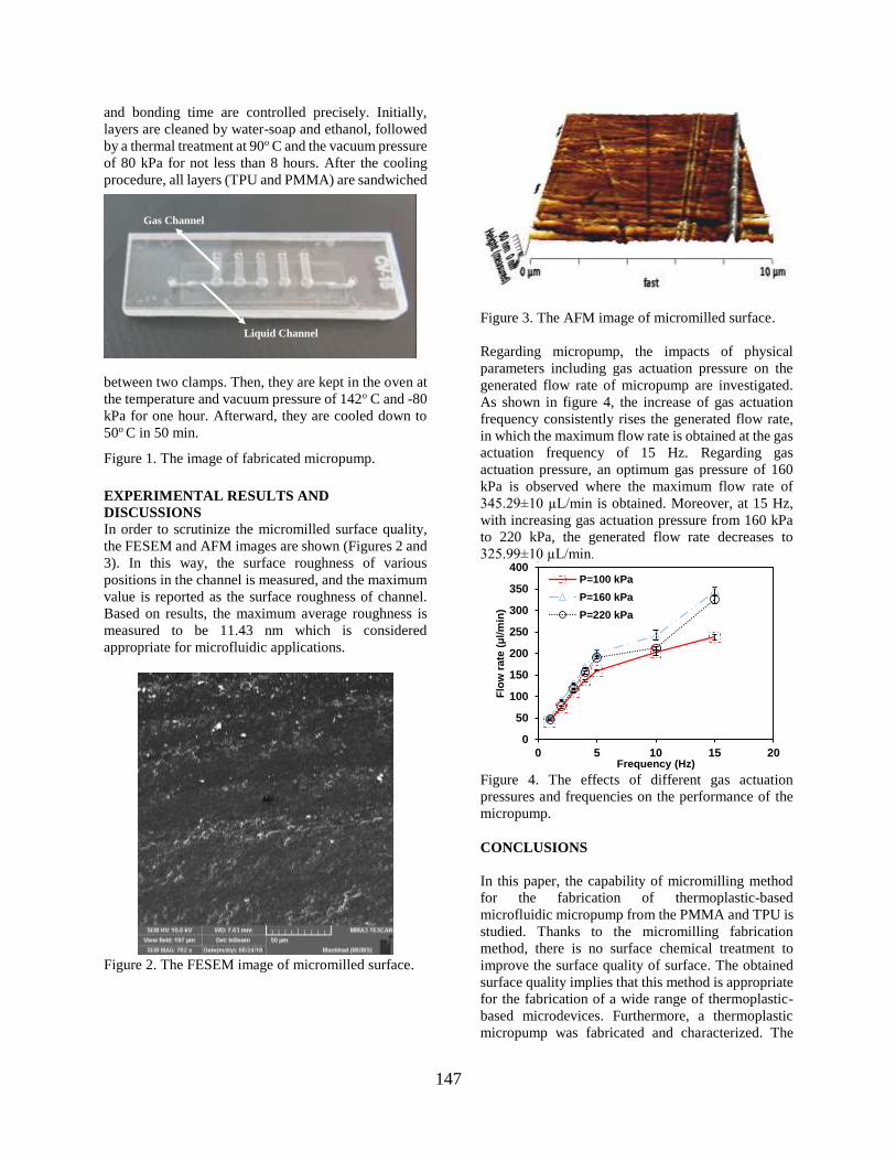
147
and bonding time are controlled precisely. Initially,
layers are cleaned by water-soap and ethanol, followed
by a thermal treatment at 90o C and the vacuum pressure
of 80 kPa for not less than 8 hours. After the cooling
procedure, all layers (TPU and PMMA) are sandwiched
between two clamps. Then, they are kept in the oven at
the temperature and vacuum pressure of 142o C and -80
kPa for one hour. Afterward, they are cooled down to
50o C in 50 min.
Figure 1. The image of fabricated micropump.
EXPERIMENTAL RESULTS AND
DISCUSSIONS
In order to scrutinize the micromilled surface quality,
the FESEM and AFM images are shown (Figures 2 and
3). In this way, the surface roughness of various
positions in the channel is measured, and the maximum
value is reported as the surface roughness of channel.
Based on results, the maximum average roughness is
measured to be 11.43 nm which is considered
appropriate for microfluidic applications.
Figure 2. The FESEM image of micromilled surface.
Figure 3. The AFM image of micromilled surface.
Regarding micropump, the impacts of physical
parameters including gas actuation pressure on the
generated flow rate of micropump are investigated.
As shown in figure 4, the increase of gas actuation
frequency consistently rises the generated flow rate,
in which the maximum flow rate is obtained at the gas
actuation frequency of 15 Hz. Regarding gas
actuation pressure, an optimum gas pressure of 160
kPa is observed where the maximum flow rate of
345.29±10 µL/min is obtained. Moreover, at 15 Hz,
with increasing gas actuation pressure from 160 kPa
to 220 kPa, the generated flow rate decreases to
325.99±10 µL/min.
Figure 4. The effects of different gas actuation
pressures and frequencies on the performance of the
micropump.
CONCLUSIONS
In this paper, the capability of micromilling method
for the fabrication of thermoplastic-based
microfluidic micropump from the PMMA and TPU is
studied. Thanks to the micromilling fabrication
method, there is no surface chemical treatment to
improve the surface quality of surface. The obtained
surface quality implies that this method is appropriate
for the fabrication of a wide range of thermoplastic-
based microdevices. Furthermore, a thermoplastic
micropump was fabricated and characterized. The
0
10
20
30
40
50
60
70
80
0 2 4 6 8
Flo
w r
ate
(µl/min
)
Liquid Height (cm)
P=200 kPa, F=2Hz
0
50
100
150
200
250
300
350
400
0 5 10 15 20
Flo
w r
ate
(µl/min
)
Frequency (Hz)
P=100 kPa
P=160 kPa
P=220 kPa
a) b)
Gas Channel
Liquid Channel

148
fabricated micropump can generate a maximum flow
rate of about 350 μL/min at an actuation gas pressure
and frequency of 160 kPa and 15 Hz, respectively. In
comparison with other fabrication methods, the
introduced one is more effective in terms of time and
cost. Therefore, it can be used for making various
microfluidic actuators in a research laboratory for
biomedical applications.
ACKNOWLEDGEMENTS/SOURCES OF
FUNDING
S. A. M. S. gratefully acknowledges funding by
National Institute for Medical Research Development
(NIMAD) under grant number 957144.
References
1. Weerakoon-Ratnayake, K.M., et al.,
Thermoplastic nanofluidic devices for
biomedical applications, Lab on a Chip. 17
(2017) 362-381. DOI:
https://doi.org/10.1039/C6LC01173J.
2. Voicu, D., et al., Thermoplastic microfluidic
devices for targeted chemical and biological
applications, RSC Advances. 7 (2017) 2884-
2889. DOI:
https://doi.org/10.1039/C6RA27592C.
3. Berthier, E., E.W. Young, and D. Beebe,
Engineers are from PDMS-land, Biologists are
from Polystyrenia, Lab on a Chip. 12 (2012)
1224-1237. DOI:
https://doi.org/0.1039/C2LC20982A.
4. Tsao, C.-W., Polymer Microfluidics: Simple,
Low-Cost Fabrication Process Bridging
Academic Lab Research to Commercialized
Production, Micromachines. 7 (2016) 225-
236. DOI: https://doi.org/10.3390/mi7120225.
5. Chin, C.D., V. Linder, and S.K. Sia,
Commercialization of microfluidic point-of-
care diagnostic devices, Lab on a Chip. 12
(2012) 2118-2134. DOI:
https://doi.org/10.1039/C2LC21204H.
6. Banejad, A., et al., Design, fabrication and
experimental characterization of whole-
thermoplastic microvalves and micropumps
having micromilled liquid channels of
rectangular and half-elliptical cross-sections,
Sensors and Actuators A: Physical. 301 (2020)
111713. DOI:
https://doi.org/10.1016/j.sna.2019.111713.
7. Shaegh, S.A.M., et al., Rapid prototyping of
whole-thermoplastic microfluidics with built-
in microvalves using laser ablation and
thermal fusion bonding, Sensors and Actuators
B: Chemical. 255 (2018) 100-109. DOI:
https://doi.org/10.1016/j.snb.2017.07.138.
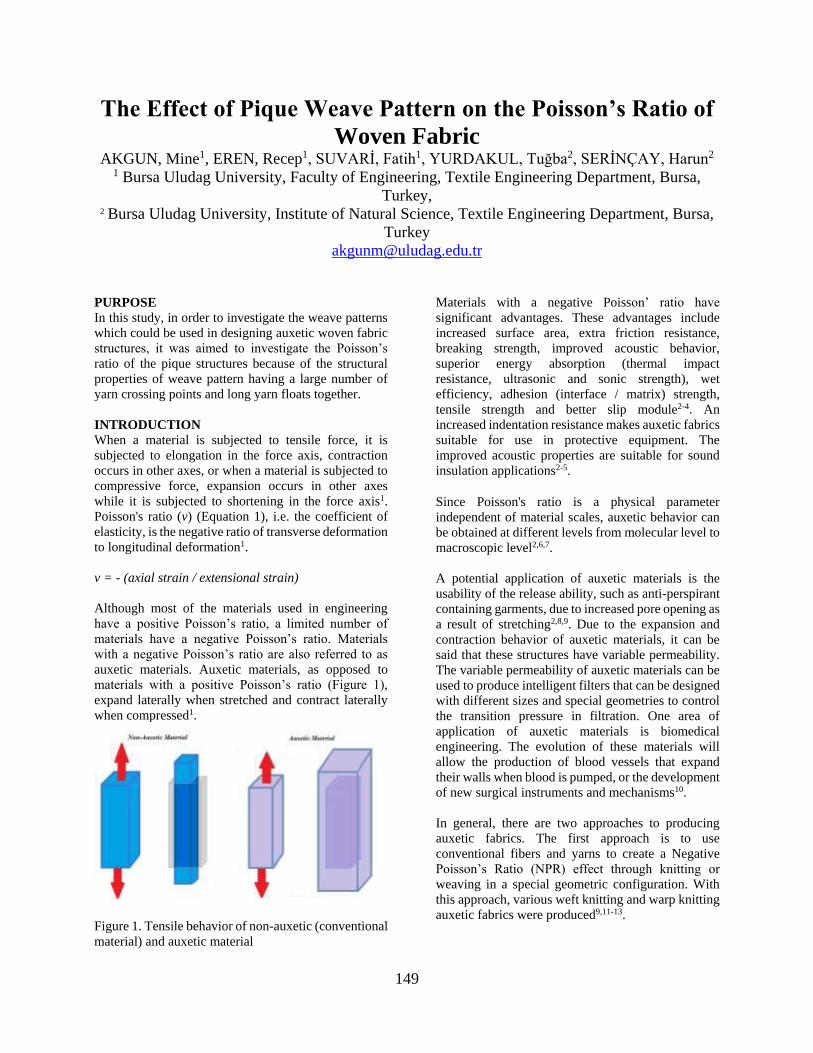
149
The Effect of Pique Weave Pattern on the Poisson’s Ratio of
Woven Fabric AKGUN, Mine1, EREN, Recep1, SUVARİ, Fatih1, YURDAKUL, Tuğba2, SERİNÇAY, Harun2
1 Bursa Uludag University, Faculty of Engineering, Textile Engineering Department, Bursa,
Turkey,
2 Bursa Uludag University, Institute of Natural Science, Textile Engineering Department, Bursa,
Turkey
PURPOSE
In this study, in order to investigate the weave patterns
which could be used in designing auxetic woven fabric
structures, it was aimed to investigate the Poisson’s
ratio of the pique structures because of the structural
properties of weave pattern having a large number of
yarn crossing points and long yarn floats together.
INTRODUCTION
When a material is subjected to tensile force, it is
subjected to elongation in the force axis, contraction
occurs in other axes, or when a material is subjected to
compressive force, expansion occurs in other axes
while it is subjected to shortening in the force axis1.
Poisson's ratio (v) (Equation 1), i.e. the coefficient of
elasticity, is the negative ratio of transverse deformation
to longitudinal deformation1.
v = - (axial strain / extensional strain)
Although most of the materials used in engineering
have a positive Poisson’s ratio, a limited number of
materials have a negative Poisson’s ratio. Materials
with a negative Poisson’s ratio are also referred to as
auxetic materials. Auxetic materials, as opposed to
materials with a positive Poisson’s ratio (Figure 1),
expand laterally when stretched and contract laterally
when compressed1.
Figure 1. Tensile behavior of non-auxetic (conventional
material) and auxetic material
Materials with a negative Poisson’ ratio have
significant advantages. These advantages include
increased surface area, extra friction resistance,
breaking strength, improved acoustic behavior,
superior energy absorption (thermal impact
resistance, ultrasonic and sonic strength), wet
efficiency, adhesion (interface / matrix) strength,
tensile strength and better slip module2-4. An
increased indentation resistance makes auxetic fabrics
suitable for use in protective equipment. The
improved acoustic properties are suitable for sound
insulation applications2-5.
Since Poisson's ratio is a physical parameter
independent of material scales, auxetic behavior can
be obtained at different levels from molecular level to
macroscopic level2,6,7.
A potential application of auxetic materials is the
usability of the release ability, such as anti-perspirant
containing garments, due to increased pore opening as
a result of stretching2,8,9. Due to the expansion and
contraction behavior of auxetic materials, it can be
said that these structures have variable permeability.
The variable permeability of auxetic materials can be
used to produce intelligent filters that can be designed
with different sizes and special geometries to control
the transition pressure in filtration. One area of
application of auxetic materials is biomedical
engineering. The evolution of these materials will
allow the production of blood vessels that expand
their walls when blood is pumped, or the development
of new surgical instruments and mechanisms10.
In general, there are two approaches to producing
auxetic fabrics. The first approach is to use
conventional fibers and yarns to create a Negative
Poisson’s Ratio (NPR) effect through knitting or
weaving in a special geometric configuration. With
this approach, various weft knitting and warp knitting
auxetic fabrics were produced9,11-13.

150
In this study, it was aimed to investigate various pique
patterns in order to guide the weave designs having
negative Poisson’s ratio which can give an auxetic
effect to create pore opening with tensile effect.
EXPERIMENTAL
Material
In the study, 100 % cotton pique fabrics with different
weave structures were used. Fabric constructional
properties were presented in Table 1. Microscopic
images with 10 times magnification of pique fabrics
were presented in Figure 2.
Table 1. Constructional properties of fabrics Fabric
Code
Yarn Count
[Nm]
Yarn Density
[Thread/cm]
Fabric
Weight
[g/m2] Warp Weft Warp Weft
F1 26 22 28 26 208,4
F2 15 15 18 20 255,7
Figure 2. Microscopic images of F1 and F2 fabrics
Method
Tensile measurements of fabrics were made in
Shimadzu AG-X plus strength device according to
ASTM D2256 standard for warp and weft direction.
The images of the fabrics taken under tension were
taken simultaneously at certain intervals and image
analyzes were performed and Poisson’s ratios were
calculated.
EXPERIMENTAL RESULTS AND
DISCUSSIONS
The Poisson’s ratio - elongation graphs of the fabrics
are presented in Figures 3 and 4. Changes in Poisson’s
ratios were evaluated for 1cm elongation.
Figure 3. Poisson’s ratio - elongation curve of F1
fabric
Figure 4. Poisson’s ratio - elongation curve of F2
fabric
Negative Poisson’s ratio was obtained in the warp
direction of F2 pique structure and under 1mm
elongation. Under the extension of 1 mm, in which the
negative Poisson’s ratio was obtained, there was an
expansion in the transverse direction in the fabrics
subjected to tension in the warp direction.

151
This might indicated that such structures could be used
under conditions of stretching, where the pore opening
due to stress was desired (such as medical gauzes, as
well as use where moisture, air and water vapor
permeability may be desired).
When the structural properties of F2 fabric in which
negative Poisson’s ratio was obtained, it was observed
that this fabric has thicker yarns and lower fabric
density values than F1 fabric.
In addition, the yarn count and density as well as the
weave pattern structure must be taken into account.
When the weave structure of the F2 fabric was
examined, it was observed that there were large yarn
intersection regions connected one-to-one between the
long warp and weft yarn floating regions.
Although a similar weave structure was also in F1
fabric, it was thought that the negative Poisson's value
could not be obtained in F1 fabric because it could be
caused both by the effect of yarn counts and density
values, and also because of the narrow yarn intersection
regions connected one-to-one between the long warp
and weft yarn floating regions in the weave structure.
The fact that the one-to-one intersection zones were
located in a narrow area indicated that it could not
produce an expansion due to the applied tensile in the
areas where the long yarn floating areas were dominant.
CONCLUSIONS
As a result of this study which examined pique pattern
structures that can be used in auxetic fabric design, it
was observed that auxetic effect was obtained in an
applied tension of approximately 1mm with proper
placement of the yarn connection areas.
SUGGESTIONF FOR FURTHER WORK
Work continues on fabric constructions with different
structural parameters and pique pattern structures.
ACKNOWLEDGEMENTS/SOURCES OF
FUNDING
This research has been supported by TUBITAK 1001
project (Project No. 119M358). The authors would like
to thank TUBITAK for their support.
LITERATURE
1. Uzun, M. 2010. “Negatif Poisson Oranına Sahip
(Auxetic) Malzemeler ve Uygulama Alanları”, Tekstil
ve Mühendis, 77, 13-18.
2. Darja R., Tatjana R., Alenka, P. C. 2013. “Auxetic
Textiles”, Acta Chim. Slov., 60, 715–723.
3. Evans, K., Alderson, A. 2000. “Auxetic Materials:
Functional Materials and Structures from Lateral
Thinking”, Advanced Materials, 12, 617– 628.
4. Yang, W., Li, Z. M., Shi, W., Xie, B. H., Yang, M.
B. J. 2004. “Review on auxetic materials”, Journal of
Materials Science,39, 3269–3279.
5. Grima, J. N., Attard, D., Gatt, R., Cassar, R. N.
2009. “A novel process for the manufacture of auxetic
foams and for their reconversion to conventional
form”, Adv. Eng. Mater., 11, 533-535.
6. Grima, J. N., Farrugia, P. S., Gatt, R., Attard, D.
2008. “On the properties of auxetic meta-tetrachiral
structures”, Phys. Stat. Sol. (b), 245, 521–529.
7. Liu, Y., Hu, H. 2010. “A review on auxetic
structures and polymeric materials”, Scientific
Research and Essays, 5,1052-1063.
8. Alderson, K. L. 2007. “Positive development in
negative materials”, Mater. World,15, 32–34.
9. Ugbolue, S. C., Kim, Y. K., Warner, S. B., Fan, Q.,
Yang, C., Kyzymchuk, O., Feng, Y. 2010. “The
formation and performance of auxetic textiles. Part I:
theoretical and technical considerations”, J. Text.
Inst., 101, 660–667.
10. Carneiro, V. H., Meireles, J., Puga, H. 2013.
“Auxetic Materials – A Review”, Materials Science,
31, 561-571.
11. Liu, Y., Hu, H., Lam, J. K. C., Liu, S. 2010.
“Negative Poisson’s ratio weft-knitted fabrics”, Text.
Res. J., 80, 856–863.
12. Hu, H., Wang, Z. Y., Liu, S. 2011. “Development
of auxetic fabrics using flat knitting technology”,
Text. Res. J., 81, 1493–1502.
13. Ugbolue, S. C., Kim, Y. K., Warner, S. B., Fan,
Q., Yang, C., Kyzymchuk, O., Feng, Y., Lord, J.
2011. “The formation and performance of auxetic
textiles. Part II: geometry and structural properties”,
J. Text. Inst., 102, 424–433.

152
RECYCLED CARBON FIBER FOR PROTECTIVE
CLOTHING APPLICATIONS KAYNAK, İdris
Uşak University
ABSTRACT
Recycled carbon fibers was carried out using with
converted into cheesecloth sheet using standard-
universal carding machine processing to obtain
technical textile products as a first step. This product
was converted to tow profile form as an intermediate
process step to obtain yarn. These forms were subjected
to tensile-bending-folding process by combining 6
pieces. The yarn had been subjected to the lubrication
and holding process for obtaining the one-way spin of
orientation fibers process. Open-end machine was used
to obtain yarn and the machine velocity was chosen
approximately 12,000 rev / min. Using the conventional
glove knitting machine, 6 of these yarns were used
together to obtain protective gloves. With the use of
carbon fibers from recycling, it was observed that the
knitted glove endured to a temperature of
approximately 400 degrees and remained in the form of
knitting and did not burn in laboratory experiments. The
total weight of the single glove was determined to be 20
grams.
Keywords: Recycled carbon fibers, Protective clothing,
Non-flammable yarn, Knitting, Glove, Light yarn.
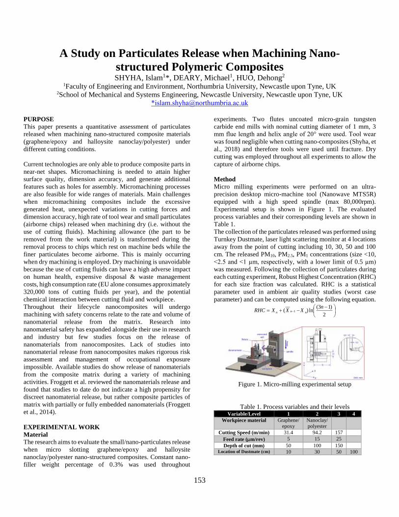
153
A Study on Particulates Release when Machining Nano-
structured Polymeric Composites SHYHA, Islam1*, DEARY, Michael1, HUO, Dehong2
1Faculty of Engineering and Environment, Northumbria University, Newcastle upon Tyne, UK 2School of Mechanical and Systems Engineering, Newcastle University, Newcastle upon Tyne, UK
PURPOSE
This paper presents a quantitative assessment of particulates
released when machining nano-structured composite materials
(graphene/epoxy and halloysite nanoclay/polyester) under
different cutting conditions.
Current technologies are only able to produce composite parts in
near-net shapes. Micromachining is needed to attain higher
surface quality, dimension accuracy, and generate additional
features such as holes for assembly. Micromachining processes
are also feasible for wide ranges of materials. Main challenges
when micromachining composites include the excessive
generated heat, unexpected variations in cutting forces and
dimension accuracy, high rate of tool wear and small particulates
(airborne chips) released when machining dry (i.e. without the
use of cutting fluids). Machining allowance (the part to be
removed from the work material) is transformed during the
removal process to chips which rest on machine beds while the
finer particulates become airborne. This is mainly occurring
when dry machining is employed. Dry machining is unavoidable
because the use of cutting fluids can have a high adverse impact
on human health, expensive disposal & waste management
costs, high consumption rate (EU alone consumes approximately
320,000 tons of cutting fluids per year), and the potential
chemical interaction between cutting fluid and workpiece.
Throughout their lifecycle nanocomposites will undergo
machining with safety concerns relate to the rate and volume of
nanomaterial release from the matrix. Research into
nanomaterial safety has expanded alongside their use in research
and industry but few studies focus on the release of
nanomaterials from nanocomposites. Lack of studies into
nanomaterial release from nanocomposites makes rigorous risk
assessment and management of occupational exposure
impossible. Available studies do show release of nanomaterials
from the composite matrix during a variety of machining
activities. Froggett et al. reviewed the nanomaterials release and
found that studies to date do not indicate a high propensity for
discreet nanomaterial release, but rather composite particles of
matrix with partially or fully embedded nanomaterials (Froggett
et al., 2014).
EXPERIMENTAL WORK
Material
The research aims to evaluate the small/nano-particulates release
when micro slotting graphene/epoxy and halloysite
nanoclay/polyester nano-structured composites. Constant nano-
filler weight percentage of 0.3% was used throughout
experiments. Two flutes uncoated micro-grain tungsten
carbide end mills with nominal cutting diameter of 1 mm, 3
mm flue length and helix angle of 20° were used. Tool wear
was found negligible when cutting nano-composites (Shyha, et
al., 2018) and therefore tools were used until fracture. Dry
cutting was employed throughout all experiments to allow the
capture of airborne chips.
Method
Micro milling experiments were performed on an ultra-
precision desktop micro-machine tool (Nanowave MTS5R)
equipped with a high speed spindle (max 80,000rpm).
Experimental setup is shown in Figure 1. The evaluated
process variables and their corresponding levels are shown in
Table 1.
The collection of the particulates released was performed using
Turnkey Dustmate, laser light scattering monitor at 4 locations
away from the point of cutting including 10, 30, 50 and 100
cm. The released PM10, PM2.5, PM1 concentrations (size <10,
<2.5 and <1 µm, respectively, with a lower limit of 0.5 µm)
was measured. Following the collection of particulates during
each cutting experiment, Robust Highest Concentration (RHC)
for each size fraction was calculated. RHC is a statistical
parameter used in ambient air quality studies (worst case
parameter) and can be computed using the following equation.
Figure 1. Micro-milling experimental setup
Table 1. Process variables and their levels Variable/Level 1 2 3 4
Workpiece material Graphene/ epoxy
Nanoclay/ polyester
Cutting Speed (m/min) 31.4 94.2 157
Feed rate (m/rev) 5 15 25
Depth of cut (mm) 50 100 150 Location of Dustmate (cm) 10 30 50 100
2
)13(ln)( 1
nXXXRHC nnn

154
RESULTS AND DISCUSSIONS
UK EH40 work exposure limit (WEL) for respirable dust (i.e.
<4µm) is 4,000 µg/m3, which is above all of the experimental
conditions tested in this study. However, a small number of trials
at different cutting conditions exceeded the IOM recommended
limits of 1000 µg/m3, see Figure 2. For almost all of the
experiments, the peak of particulates concentration obtained at
10 cm away from the tool tip regardless of cutting conditions
used, see Figure 3. Principal Component Analysis (PCA) was
used to determine the relationships between concentrations and
the process variables as shown in Figure 4. The size of circle is
proportional to PM10 concentration while the colours indicate
distance categories. Closely aligned arrows indicate positive
correlations (e.g. PM10 with depth of cut). Oppositely aligned
arrows indicate negative correlation (e.g. PM10 and distance).
PM1 and PM2.5 are more closely aligned with each other than
they are with PM10. Orange and red circles (closer distances),
clearly associated with highest concentrations. In general,
graphene/epoxy material had higher concentrations compared
with clay/polyester regardless of cutting conditions and distance
from tool tip, see Figure 5. Also, the PM10 fraction is found to
be closely associated with changes in cutting parameters (i.e.
compared to PM2.5 and PM1), suggesting that most particulates
produced are within this category. There is limited information
on health hazards of nanoparticles (<0.1µm) and so, even though
our study suggests low concentrations of this size fraction are
generated, these concentrations may still be associated with
significant health effects which means adequate precautions
need to be taken.
Figure 2. RHC for PM10 (µg/m3)
Figure 3. Effect of milling conditions on PM10 concentration at
different locations
Figure 4. PCA for PM10 concentration
Figure 5. Effect of work material on PM10 at different
locations
CONCLUSIONS
Within the evaluated operating conditions, released particulate
concentrations for most of the experiments were below the
recommendation WEL for respirable dust (i.e. 1000 g/m3
recommended by IOM). It does not mean coming in under the
available WELs, it is ok to machine nanocomposites with no
extraction. Therefore, this work draws attention to the need for
new WELs for nanomaterials and output from nanocomposites
machining because current legal limits applied could really lull
people into a false sense of security.
SUGGESTIONS FOR FURTHER WORK
The future work will need to focus on characterising
morphology and toxicity of the particulates generated from
micromachining nano-structured composites.
ACKNOWLEDGEMENTS/SOURCES
The authors would like to thank Mr. Guoyu Fu and Mr.
Xiangyu Teng from Newcastle University for helping in
conducting some of the experiments.
REFERECES
Froggett et al., 2014, “A review and perspective of existing research on the
release of nanomaterials from solid nanocomposites”, Particle and Fibre
Toxicology, volume 11.
Shyha, I. et al., 2018, “Micro-machining of nano-polymer composites reinforced with graphene and nano-clay fillers”, Int. Con. on Materials Sci. &
Eng.: Recent Advances and Challenges, March 11 – 13, Alexandria, Egypt