brochure_steam gas turbine power plants_en
TRANSCRIPT
GEA Mechanical Equipment / GEA Westfalia Separator Group
Liquids to Value
Energy System Technology High Performance Equipment for Steam and Gas Turbine Power Plants

GEA Westfalia Separator Group – your partner for complete system solutions
Power producers operating gas turbine power plants
can save enormous costs – also in existing plants – by
installing fuel oil treatment systems in their gas
turbine power plants.
Efficient treatment of diesel oil, heavy fuel oil and
crude oil drastically reduces the gas turbine blades‘
susceptibility to corrosion. This means the time
until the next overhaul is significantly extended.
Overhauling a gas turbine (including power outage)
is very cost-intensive.
Treatment systems from GEA Westfalia Separator
Group therefore protect the core investment of the
plant – the gas turbine. If stand-by liquid fuel is used,
gas fired power plants also need a fuel oil treatment
system from GEA Westfalia Separator Group.
High-Tech Solutions to Protect Your Investment
Applications
• Fueloildesalting
• Separationofoilysludge
• Separationofwastewater
• Lubeoilseparation
• Systemengineering
2
Protection for Your Investment
2 High-Tech Solutions to Protect Your Investment
4 The Core of Your Power Station Needs
High Performance Systems
Technology and Function
6 Why Self-Cleaning Separators?
For Continuous Operation!
System Overview
8 System Overview: Complete Solutions
for Gas Turbine Power Plants
Treatment Know-How
10 Diesel Oil Treatment
12 Crude Oil Treatment
14 Heavy Fuel Oil Treatment
16 Waste Water Treatment
17 Sludge Treatment
18 Lube Oil Treatment
Overview of Benefits
20 Maximum Economy Through Significantly
Extending the Service Life of Your Turbines
Service & Support
22 Westfalia Separator® capitalcare –
Proactive Service for Optimum Reliability
in Power Plants
Contents
Oil Refinery
Fuel Oil
Treatment System
Protect Your
Gas Turbine
3

Complete systems or stand-alone solutions from GEA Westfalia Separator Group ensure an efficient treatment of gas turbine liquid fuels.
The Core of Your Power Station Needs High Performance Systems
The power station industry often uses gas
turbines running on diesel oil, crude oil or
heavy fuel oil. By supplying systems specifically
designed for continuous operation under
roughest conditions, GEA Westfalia Separator Group
provides for optimum power output and a long
service life for these turbines while taking into
consideration the high environmental standards.
This holistic problem-solving approach leads to a
substantial cost reduction. Efficient fuel treatment
significantly extends the service life of the gas
turbine. To achieve this aim, fuel oil treatment
systems from GEA Westfalia Separator Group
realize the task of dewatering the oil and reducing the
water-soluble salts like NaCl, KCl and CaCl to the
values required by the gas turbine manufacturers as
well as separating the solids from the fuel.
Prevent damages for longer service life
Features
• Excellentreductionofwater-solublesalts
• Gooddewateringoffuel
• Separationofabrasive,heavysolids
downtomicron-range
4

An efficient and economical solution
The quality specifications for gas turbine fuel oils
are extremely stringent. Harmful trace elements
such as water-soluble sodium, potassium and
calcium as well as oil-soluble vanadium and lead
can cause major problems. An excessively high
concentration of trace elements in the fuel results in
corrosion. Sediments such as sand, rust and cat fines
lead to increased wear.
Fuel oil treatment systems from GEA Westfalia
Separator Group offer an efficient and economical
solution. The gas turbine manufacturers specify limits
for the trace elements to ensure safe and economical
operation. For sodium and potassium these limits are
between 1 ppm and 0.1 ppm.
The harmful water-soluble trace elements are
reduced to the required levels by separation only
or by a combination of washing and separation.
Contaminants such as sand, rust and cat fines are
removed from the fuel oil under high centrifugal force.
Oil-soluble trace elements as for example
vanadium and lead cannot be separated. A suitable
inhibitor is added to the fuel to counteract the high
temperature corrosion caused by vanadium ash.
Self-cleaning separators with disc-type bowl are
used for purifying and dewatering the fuel oil. An
essential feature of the separators is the optimum
separation efficiency even with constantly
changing composition of the product to be separated.
A requirement for efficient separation is a density
difference between water, oil and solids.
Benefits of high performance systems
• Increaseofturbinelife-time
•Necessarygeneraloverhauling
ofgasturbineatlongerintervals
•Reductionofgasturbine´s”PowerLoss“
•Reductionofoperatingcostsfor
downstreamequipment
The dramatically increasing energy demand can be met only by high-efficient power plants. GEA Westfalia Separator Group offers system solutions for profitable operation – for example of gas turbine power plants.
5

Why Self-Cleaning Separators? For Continuous Operation!Optimum separation efficiency over long operating times
Self-cleaning separators from GEA Westfalia
Separator Group with disc bowl and Westfalia
Separator® softstream inlet as well as automatic solids
ejection with Westfalia Separator® hydrostop are
mainly used where the percentage of solids in the oil
is too high for manual cleaning. The separated solids
slide down the underside of the disc into the solids
hold ing space. Our self-cleaning separators eject
solids automatically while the separator is running.
This avoids shutting down the separator frequently
for cleaning. The clean oil and the sepa rated water are
conveyed to the discharge under pressure by a twin
centripetal pump.
Self-cleaning separators from GEA Westfalia
Separator Group operate continuously. Solids
ejection occurs either by total or partial ejections.
In case of total ejection, there is an additional self-
clean ing effect of the disc stack.
These unique features avoid labour-intensive
and costly measures to clean the discs. Therefore
CIP-systems (cleaning in place with chemicals) are
not necessary. Additionally, optimum separation
efficiency over long operating times is ensured.
Major maintenance work is required only after 8000
to 16,000 hours.
Features
•Automaticandcontinuous
operatingmode
•Self-cleaningeffectofthebowl
•Highlyconcentratedsolids
•Highseparationefficiency
•Dischargeofthelightandheavyphase
underpressurebycentripetaltwinpump
• Lownoiselevel
•Beltdrive
6
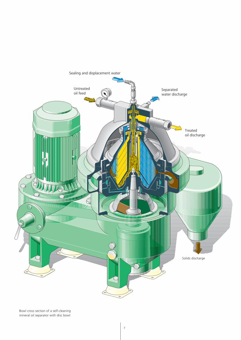
Bowl cross section of a self-cleaning mineral oil separator with disc bowl
Sealinganddisplacementwater
Solids discharge
Untreatedoilfeed
Treatedoildischarge
Separatedwaterdischarge
7

Heavy fuel oil
Crude oil
Diesel oil
Treatedtank
Gas turbine
Forwarding pumpmodule
Filteringmodule
Transporting
Sludge andwaste water treatment
Heating module Inhibitor dosingmodule
Fuel oil treatmentmodule
Heat recovery moduleDemulsifier dosingmodule
Transfer pumpmodule
Unloadingmodule
Lube oiltreatment
Untreatedtank
Oil refinery
Laboratoryequipment
Unloading Treatment Forwarding
System Overview: Complete Solutions for Gas Turbine Power PlantsGEA Westfalia Separator Group – your system partner for reliable and economical solutions
By using innovative technologies and having
a unique process competence, GEA Westfalia
Separator Group develops jointly with the customers
highly profitable fuel oil treatment systems for
gas turbine power plants.
From analyzing the problems up to the installation of
the system GEA Westfalia Separator Group masters
all process stages for diesel oil, heavy fuel oil and
crude oil, thus offering to the customer profitable
benefits in the form of complete problem
solutions.
On its way from the refinery to the power plant the
oil possibly gets contaminated with salt water,
dust and particles. The most dangerous salts are sodium
and potassium (i.e. common salts) which lead to
corrosion at the blades. The characteristics of
corrosion are: once having started, it proceeds
continuously if oil with an excessively high salt
content is burnt.
The treatment system is designed as a complete
system, installed on modules with all separators,
pumps, controls, etc.
8

Heavy fuel oil
Crude oil
Diesel oil
Treatedtank
Gas turbine
Forwarding pumpmodule
Filteringmodule
Transporting
Sludge andwaste water treatment
Heating module Inhibitor dosingmodule
Fuel oil treatmentmodule
Heat recovery moduleDemulsifier dosingmodule
Transfer pumpmodule
Unloadingmodule
Lube oiltreatment
Untreatedtank
Oil refinery
Laboratoryequipment
Unloading Treatment Forwarding
Benefits of complete systems
•Processcompetencefromonesource
•Reductionofinterfaces
• Integratedmodularsystem
•Highlyefficientdesaltingofoils
•Reductionofcorrosionforlongerlife-time
9
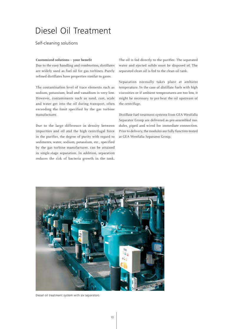
Diesel oil treatment system with six separators
Customized solutions – your benefit
Due to the easy handling and combustion, distillates
are widely used as fuel oil for gas turbines. Purely
refined distillates have properties similar to gases.
The contamination level of trace elements such as
sodium, potassium, lead and vanadium is very low.
However, contaminants such as sand, rust, scale
and water get into the oil during transport, often
exceeding the limit specified by the gas turbine
manufacturer.
Due to the large difference in density between
impurities and oil and the high centrifugal force
in the purifier, the degree of purity with regard to
sediments, water, sodium, potassium, etc., specified
by the gas turbine manufacturer, can be attained
in single-stage separation. In addition, separation
reduces the risk of bacteria growth in the tank.
The oil is fed directly to the purifier. The separated
water and ejected solids must be disposed of. The
separated clean oil is fed to the clean oil tank.
Separation normally takes place at ambient
temperature. In the case of distillate fuels with high
viscosities or if ambient temperatures are too low, it
might be necessary to pre-heat the oil upstream of
the centrifuge.
Distillate fuel treatment systems from GEA Westfalia
Separator Group are delivered as pre-assembled mo -
dules, piped and wired for immediate connection.
Prior to delivery, the modules are fully function-tested
at GEA Westfalia Separator Group.
Diesel Oil TreatmentSelf-cleaning solutions
10

1
4
2
7
8
3 5 6
1 Untreated oil feed
2 Dilution water
3 Operating water
4 Feed pump
5 Self-cleaning separator
6 Solids discharge
7 Treated oil discharge
8 Separated water discharge
11

Safety first
More and more crude oil is used in gas turbine power
plants. The crude oil is delivered to the power plant
in a pre-cleaned and degassed condition. However,
after pre-cleaning the fuel quality is still too poor to
be burnt in a gas turbine.
The viscosity range is from diesel oil to heavy
fuel oil. As crude oil contains wax, the separating
temperature has to be min. above the melting
point. For higher viscosity crude oils, the separating
temperature depends on viscosity. Due to the low
flash point, the system must be equipped with
explosion protection.
Centrifuges are essential for the efficient control and
removal of solids and water with salt from fuel oils;
they will continue to be so in the future.
Crude oil fuels from different sources must be
purified efficiently. This treatment protects the
gas turbine.
The whole plant concept for crude oil treatment is
rounded off with all necessary auxiliaries.
Crude Oil TreatmentPlant concepts with a system
12

Process Overview
Under normal circumstances, GEA Westfalia
Separator Group recommends single-stage treatment
for light crude oils.
The high efficiency of separation in a single-stage
process ensures low corrosion and wear of the
gas turbine. The high reliability and long service
intervals ensure low operating costs and continuous,
unattended automatic operation for months.
All equipment with electrical components is
suitable for use in hazardous areas in accordance with
the latest codes or rules and regulations.Crude oil treatment system with three separators
1
2
3
4
5
7
6
8
11109
1 Untreated oil feed
2 Treated oil discharge
3 Dilution water
4 Separated water discharge
5 Feed pump
6 Demulsifier
7 Heat exchanger
8 Pre-heater
9 Solids discharge
10 Self-cleaning separator
11 Operating water
13

Protect your gas turbine
Due to its low price, residual oil is widely available
on the international market. During combustion
however, impurities cause corrosion and deposits.
Depending on the application, treatment systems
are available for high-grade and low-grade fuels
as well.
When rating the throughput capacity of the plant,
the following fuel oil data are of central importance:
• Viscosity (cSt)
• Density (kg / l)
• Solids and liquid impurities (%)
• Content of sodium and potassium
Centrifuges are essential for the efficient control
and removal of solids and water with salt from
fuel oils. Low-grade fuels from different refining
processes must be purified efficiently.
Heavy fuel oils normally contain higher levels of
harmful trace elements such as sodium and potassium.
With two-stage counter-current washing systems,
the degree of purity specified by the gas turbine
manufacturers is attained, and the water-soluble trace
metal elements are reduced to the specified limits.
Heavy Fuel Oil Treatment
Desalting module for fuel oil washing
Plant concepts with a system
14

17
Process flow
The heavy fuel oil is first fed to a pre-strainer. After
adding demulsifier to facilitate separation of the
dilution water in the purifier, the oil is conveyed
to a heat exchanger and is heated to the required
temperature. The water separated from the oil in
the second stage is added upstream of the
first-stage mixer. The heavy fuel oil is mixed with the
water in a multi-stage mixer. Salts in solution with
the oil are extracted into the water. The oil/water
mixture flows to the purifier in the first washing
stage. The solids are spun out due to the high
centrifugal force, and the dissolved salts, together
with the dilution water, are simultaneously separated
out. Water is again added to the purified oil of the
second-stage mixer. In the second washing stage,
further purification and desalting takes place.
1
2
4
5
6
7
8
9 10
11
12 14 15 16
18
13
3
1 Dilution water
2 Untreated fuel oil return
3 Pre-heater
4 Untreated fuel oil feed
5 Treated fuel oil discharge
6 Separated water discharge
7 Demulsifier
8 Feed pump
9 Heat exchanger
10 Pre-heater
11 Multi-stage mixer 1
12 Operating water
13 Self-cleaning separator 1
14 Solids discharge
15 Operating water
16 Self-cleaning separator 2
17 Solids discharge
18 Multi-stage mixer 2
15
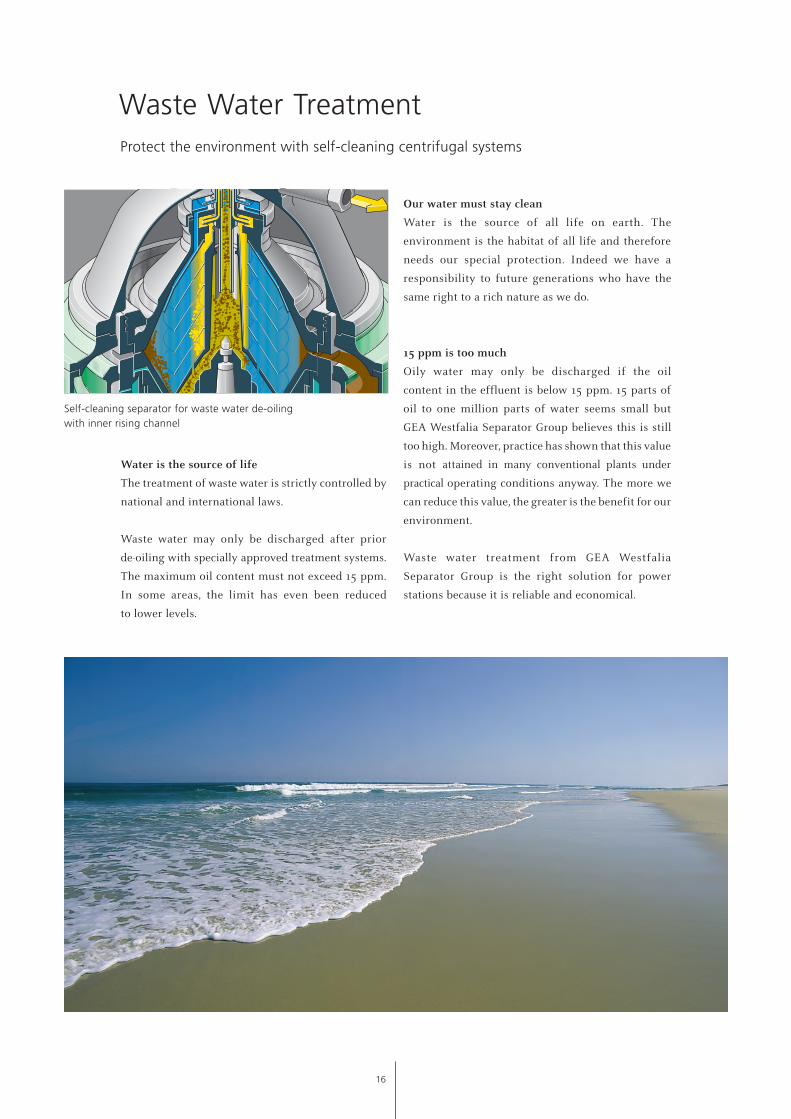
Waste Water TreatmentProtect the environment with self-cleaning centrifugal systems
Our water must stay clean
Water is the source of all life on earth. The
environment is the habitat of all life and therefore
needs our special protection. Indeed we have a
responsibility to future generations who have the
same right to a rich nature as we do.
15 ppm is too much
Oily water may only be discharged if the oil
content in the effluent is below 15 ppm. 15 parts of
oil to one million parts of water seems small but
GEA Westfalia Separator Group believes this is still
too high. Moreover, practice has shown that this value
is not attained in many conventional plants under
practical operating conditions anyway. The more we
can reduce this value, the greater is the benefit for our
environment.
Waste water treatment from GEA Westfalia
Separator Group is the right solution for power
stations because it is reliable and economical.
Water is the source of life
The treatment of waste water is strictly controlled by
national and international laws.
Waste water may only be discharged after prior
de-oiling with specially approved treatment systems.
The maximum oil content must not exceed 15 ppm.
In some areas, the limit has even been reduced
to lower levels.
Self-cleaning separator for waste water de-oiling with inner rising channel
16

System concepts for the future
Save natural resources
The trend towards burning higher viscosity
and higher density fuel oils, together with an
increasingly common usage of residuals, means that
the amount of sludge being created from both, fuel
and lube oil systems, is increasing.
Economical advantages – ecological merits
Approximately 2.5 percent of a power plant´s fuel
consumption remains as an unwanted by-product in
the form of an oily water sludge mixture.
With increasing environmental awareness as well
as strict regulations and controls, most operators
dispose of this sludge by incineration or by shoreside
disposal using contract companies. In either case
sludge disposal is becoming an expensive problem
for the op erators today.
The GEA Westfalia Separator Group sludge treatment
plant incorporates a specially designed centrifugal
separator or a decanter. The sludge concentration
system is capable of reducing the volume of
sludge for disposal by up to 90 percent. In addition,
oil is recovered and can be used as boiler fuel. A
very economical solution is a combination of both,
waste water treatment system with integrated
sludge concentration system.
Sludge Treatment
Features
•Savesupto90percentdisposalcosts
•Recoversvaluablefueloil
•Unburdensthewastewatersystem
fromoilresidues
•Protectsoursensitiveecosystem
3-phase decanter for sludge concentration Self-cleaning separator for sludge concentration
17

Lube Oil TreatmentPlant concepts for efficient operation
Sealing water
Untreated oil feed
Treated oil discharge
Separated water discharge
Westfalia Separator® lifecyclebenefit®
During operation, the turbine lube oils are subject
to continuous contamination. Fine metal particles
from rotating or sliding parts as well as dust,
condensate and decomposition products deposit
in the lube oil sump. Furthermore, lube oils can be
contaminated with acids, causing aging of the oil
when reacting with impurities.
Besides removing the contaminants resulting from
metal abrasion, it is also essential to completely
separate out the water which has penetrated
into the lube oil system to inhibit premature
aging of the oil.
Purification and dewatering with centrifugal
separators offers an efficient and economical
solution for this application.
Manual cleaning separators with solid-wall bowl and
single centripetal pumps are today mostly used for
the treatment of this lube oil. They are suitable for
clarifying or purifying oils with a low solids content
of up to 0.01 percent by vol.
Bowl cross section of a manual cleaning mineral oil separator with pressure discharge of the clean oil by centripetal pump
18

Mobile unit with manual cleaning separator
Features of continuous lube oil
purification in bypass
•Efficientseparationofsolidand
liquidimpurities
• Substantialimprovementinthe
usefullifeofthelubeoil
•Considerablesavingsinlubeoilcosts
• Lowerdisposalcosts
• Lowwearonthebearings
•Noundesirablestoppages
The ideal operating mode is continuous lube oil
purification in bypass. In this way, the solid and
liquid impurities are continuously removed from
the oils.
Best clarifying and separating results are obtained
with low viscosities of the oil to be purified. It is
therefore advantageous to pre-heat the oil. Electric
heaters and steam or hot water heaters are applied
for this purpose.
1
2
3
4 5
6
1 Untreated oil feed
2 Feed pump
3 Pre-heater
4 Separated water discharge
5 Manual cleaning separator
6 Treated oil discharge
19

Maximum Economy Through Significantly Extending the Service Life of Your Turbines
With a complete system for fuel and lube oil treatment
you can increase the life-time of your turbine
Life-time of gas turbine blade
20

GEA Westfalia Separator Group provides various
systems, tailor-made to customers‘ needs.
• Modern module design ready
for installation
• System intergration into the
power plant concept
• Engineering and total system design
All available from GEA Westfalia Separator
Group.
Result: commissioning of a treatment system by
your system partner GEA Westfalia Separator Group in
your gas turbine power plant increases the service life
of the gas turbine blade enormously and extends the
overhaul intervals clearly.
At the same time, the energy losses during operation
are substantially reduced, and the operating costs of
the downstream aggregates are optimized due to the
better quality of the fuel oil.
Benefit overview
• Higherlife-timeofgasturbineblades
• Extendedoverhaulintervals
• Reductionofenergyloss
• Reductionofoperatingcostsfor
downstreamequipment
• Treatmentofdieseloil,heavyfueloil,
crudeoil,oilysludge,wastewaterand
lubeoil
• GEAWestfaliaSeparatorGroup–
completesystemsolutionsfromone
source
• Retrofittingseparatorsalsoprovides
allbenefits
GEA Westfalia Separator Group – your partner for complete system solutions for treatment of fuel oil, oily sludge, waste water and lube oil
Maximum Economy Through Significantly Extending the Service Life of Your Turbines
21

Safety first: this is precisely what the service concept
Westfalia Separator® capitalcare stands for.
Power plant operators not only benefit from traditional
services such as inspection, maintenance, original
spare parts and repair work provided by the origi-
nal manufacturer; they also benefit from pro-active
solutions which avoid risk, e. g. online and offline
monitoring with Westfalia Separator® wewatch®.
These preventive services are the best pre-condition
for smoothly operating lube oil and fuel treatment
systems for gas turbines.
Enhanced process efficiency also follows from
maximum operating reliability and plant availability.
Accompanying modernization or upgrading to
state-of-the-art technology also offer the option of
boosting performance as required.
Westfalia Separator® capitalcare – Proactive Service for Optimum Reliabilityin Power PlantsThe proactive, risk-free services of Westfalia Separator® capitalcare optimize operatingreliability and permanent availability of the drive systems.
Training provided on site or in the modern training
centre of GEA Westfalia Separator Group ensures that
the plant operator’s employees receive training in the
proper handling of the high-tech installations. This
provides additional safety.
Authorized workshops worldwide
And if problems occasionally occur or if a spare part
is required at short notice, the specialists are able to
attend to the customer quickly. This is ensured by a
global network with more than 50 sales and service
companies as well as 60 further sales partners.
Authorized workshops are able to service every location
in the world at short notice.
22
availabilityMaximum
budget reliabilityAbsolute
efficiencyPermanent
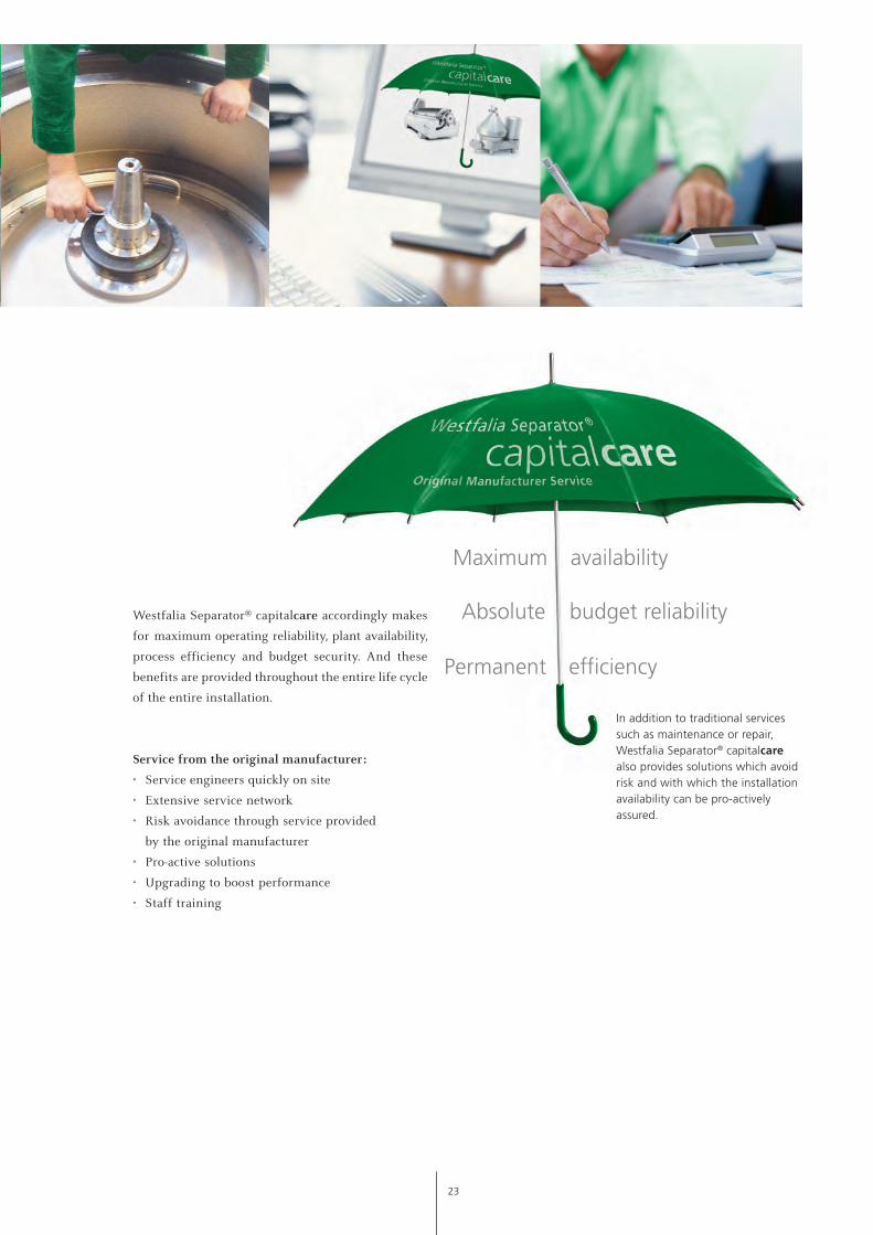
In addition to traditional services such as maintenance or repair, Westfalia Separator® capitalcare also provides solutions which avoid risk and with which the installation availability can be pro-actively assured.
Westfalia Separator® capitalcare accordingly makes
for maximum operating reliability, plant availability,
process efficiency and budget security. And these
benefits are provided throughout the entire life cycle
of the entire installation.
Service from the original manufacturer:
• Service engineers quickly on site
• Extensive service network
• Risk avoidance through service provided
by the original manufacturer
• Pro-active solutions
• Upgrading to boost performance
• Staff training
23

• Beverage Technology
• Dairy Technology
• Renewable Resources
• Chemical / Pharmaceutical Technology
• Marine
• Energy
• Oil & Gas
• Environmental Technology
• Engineering
• Second Hand Machinery
• Original Manufacturer Service
The information contained in this brochure merely serves as a non-binding description of our products and is without guarantee.
Binding information, in particular relating to capacity data and suitability for specific applications, can only be provided within the framework of concrete inquiries.
Westfalia®, Westfalia Separator ® and wewatch ® are registered trademarks of GEA Mechanical Equipment GmbH.
Printed on chlorine-free bleached paper www.kabutz.de
B_EN-11-07-0001 EN Printed in Germany Subject to modification
Werner-Habig-Straße 1 · 59302 Oelde (Germany) Phone +49 2522 77-0 · Fax +49 2522 77-1778 www.westfalia-separator.com
GEA Mechanical Equipment
GEA Westfalia Separator Group GmbH