briefing for nuclear power engineering committee -...
TRANSCRIPT

NPEC Meeting July 16, 2008 1
Briefing For Nuclear Power Engineering Committee
Institute of Electrical & Electronics Engineers
Significant Loss of Safety-Related Electrical Power
at Forsmark Unit 1
Thomas Koshy, Chief Mechanical & Electrical Engineering Branch
Office of Research, [email protected]

NPEC Meeting July 16, 2008 2
Forsmark stationSweden
Three Asea Atom BWR# 1: 2928 MWth 1980# 2: 2928 MWth 1981# 3: 3300 MWth 1985
NPEC Meeting July 16, 2008 3
Presentation Outline
• Forsmark Safety Systems Overview• Overview of Event• Event Details• Risk Insights• Impact on US Plants• Millstone-2 Electrical Event• Action for IEEE

NPEC Meeting July 16, 2008 4
Forsmark Safety Systems Overview
• Safety systems are divided into four trains, each with its own emergency diesel generator and capacity to manage 50% of the ECCS loads
• Two diesel generators started automatically and worked during the event

NPEC Meeting July 16, 2008 5
Overview of Event• July 25, 2006; Plant at 100%• Opened 400 kV disconnect and caused an
Electrical Fault • Generator voltage dropped to 30% • Unit disconnected from the grid• Generator over-voltage (OV) 120%• OV caused 2 of 4 UPSs to fail• 2 of 4 Emergency Diesel Generators (EDG)
failed to connect to the safety buses

NPEC Meeting July 16, 2008 6
Gas Turbine
Maintenance work in the switchyard causes an arc and a short circuit. Unit 1 is disconnected from the grid and reactor scrams.
Failure in the generator protection results in generator breaker not opening.Generator breaker should open and transfer to 70kV offsite power.
Internal power supply is divided into four separate buses/trains (A,B,C,D) for emergency power.
Rectifier and inverter on buses/trains A&B fail. Buses A&B loss power and the signal to start the EDGs fail.

NPEC Meeting July 16, 2008 7
Normal Operation
TA11 TA12

NPEC Meeting July 16, 2008 8
Supply Breakers Trip, EDG D Connects, EDG B Fails
TA11 TA12
Dead bus
Supply BreakersTrip UF
Dead bus
SlowingDown

NPEC Meeting July 16, 2008 9
Event Details• Both generator breakers should have tripped
immediately– Common Cause Failure
• Over voltage tripped two battery charges & two inverters (2/4 UPS shutdown)– Common Cause Failure
• 2/4 EDGs failed to energize the safety bus– Common design flaw
• Gas turbine failed to start– 70kV grid was available
• Loss of control room information– Loss of network power A&B

NPEC Meeting July 16, 2008 10
Risk Insights• Plant Uniqueness that influence risk :
– No steam/diesel-driven pumps (diversity w/defense in depth)
– 2 Common Cause Failures (UPS, Generator Relay Protection)
– EDG controls relied on AC power from UPS– Failure of power supplies to control room
indications– Gas Turbine didn’t start

NPEC Meeting July 16, 2008 11
Risk Insights• Inverter failures resulted in instrumentation
without power on buses A&B– Control rod indication (buses A&B)– Neutron monitoring system (channels A&B)– Reactor level & pressure indications (channels A&B) – Faulty indication on electrical system mimic panels
• EDGs A&B failed to connect– Speed sensor was powered from inverter
• Plant could have lost all four inverters, battery chargers and EDGs along with loss of offsite power
NPEC Meeting July 16, 2008 12
• Most EDG control and starting logic circuits for US nuclear power plants (NPP) are powered from the DC system instead of inverters as is the case in Forsmark
• Control and starting circuits for US NPP are supplied either from dedicated Class-1E diesel generator batteries or from Class-1E station batteries
Impact on US Plants
NPEC Meeting July 16, 2008 1313
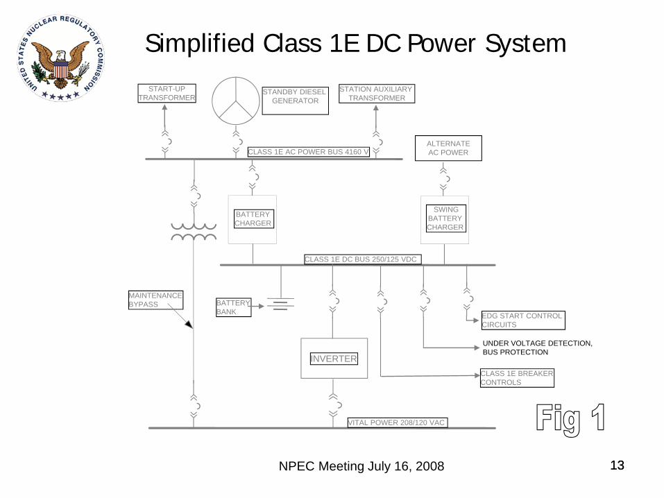
Simplified Class 1E DC Power System
UNDER VOLTAGE DETECTION, BUS PROTECTION
BATTERY CHARGER
INVERTER
MAINTENANCEBYPASS
VITAL POWER 208/120 VAC
CLASS 1E DC BUS 250/125 VDC
CLASS 1E AC POWER BUS 4160 V
STANDBY DIESEL GENERATOR
START-UPTRANSFORMER
BATTERYBANK
STATION AUXILIARY TRANSFORMER
CLASS 1E BREAKERCONTROLS
EDG START CONTROL CIRCUITS
SWINGBATTERY CHARGER
ALTERNATE AC POWER

NPEC Meeting July 16, 2008 14
Event Unlikely for US Reactors
• DC systems for US NPPs are normally supplied by the battery chargers/rectifiers which are in turn powered from the AC distribution system
• EDG battery could still supply the required DC power to start and control the emergency diesel generators loads for about 2 hours

NPEC Meeting July 16, 2008 15
Event Unlikely for US Reactors
• U.S. plants are required per the 10 CFR 50.63 to be able to keep the core cooled and maintain containment integrity with a loss of offsite power & unavailability of onsite EDGs

NPEC Meeting July 16, 2008 16
Operating Experience
• Event Notification (EN) 25162, LER 93-001-00, Sequoyah Unit 2 “Large Steam Leak in MFW Heater Extraction Header” – IN 94-77 - Main Generator OV @ 119% for 3
minutes• EN 21602, LER 91-017-01, Nine Mile Point 2
“Loss of Non-Class 1E UPS” (1991)– IN 91-64, Supplement 1 - Five UPS units shutdown
as a result of a logic initiated trip

NPEC Meeting July 16, 2008 17
Millstone-2 Electrical Event• On July 6, 1992 , during a refueling outage, the
licensee identified several undesirable failure modes of a two-out-of-four logic following an event. The plant was designed with two sensor cabinets and one actuation cabinet for each of the two trains. (Information Notice 93-11)– When power is lost to either one of the vital buses it
caused safety injection and sump recirculation actuation. – When two of the sensor cabinets in a train lost power it
caused the containment sump outlet valves to open– Loss of DC power to one actuation train caused power
operated relief valve in the other train to open• The logic was modified to limit certain
combinations of two-out-of-four logic to prevent this problem.

NPEC Meeting July 16, 2008 18
NRC Guidance on Control Systems
• Bulletin 79-27 “Loss of Non-Class 1E Instrumentation and control Power System Bus During Operation” – Evaluate the effects of loss of power to control systems
• Generic Letter 89-18 “Systems Interactions in Nuclear Power Plants” – concerns regarding automated safety related actions with no preferred failure modes

NPEC Meeting July 16, 2008 19
Action for IEEE• Consider revising IEEE 352-1987 to include
the following:– Provide design guidance to address failure
modes for reactor trip systems and core cooling systems
– Provide design guidance for addressing known failure modes in software driven systems and the supporting hardware
– Provide guidance on the defense-in-depth requirements for power supplies in the protection and information systems for reactor safety

NPEC Meeting July 16, 2008 20
EMERGENCY DIESEL
GENERATOR
ALTERNATE AC POWER
NONCLASS 1E BUS A
NON CLASS 1E BUS B
CLASS 1E BUS B
CLASS 1E BUS A
DIESEL GENERATOR
OR Other sources
SWITCHYARD
TRANSMISSION SYSTEM
FULL LOAD GENERATOR BREAKER
ONE LINE DIAGRAM FOR SINGLE UNIT NUCLEAR STATION
MAIN GENERATOR
EMERGENCY DIESEL
GENERATOR
Start up Transformers
Auxiliary Transformers
