bridge foundations dr s r
TRANSCRIPT
C'1ra ad}' )
BRIDGE FOUNDATIONS-CASE HISTORIES
Dr. S. R. KulkarniConsultant. Geologist
Bharati Vicfyapeeth Deemed University, Pune - 41i043
'rr
~1 r--
tr'
1 INTRODUCTIONThe objective of Sup-surface exploration in caseof bridges is to determine suitability of soil orrocie-If any-for the-foundationof brldges Coredrilling Is one of the most important methods ofInvestigations and is mainly discussed in thispaper. .Adequate guidelines are available invarious I.S.II.R.C codes and chapter-s of. P.W.D.handbook of Government of Maharashtra.However. In practice. these guide lines are notfaithfully followed. Investigations by core drillingis a very costly process and hence it is importantthat complete observations. are made during adrilling operation. The data provided by suchdrilling. When interpreted by a competentengineering geologist gives Valuable subsurfacegeological information. In order to extractmaximum possible information From this processand to prevent the loss of valuable sub-surfacedata obtained by costly core drilling. it isnecessary that the cores obtained are kept in agood condition. properly arranged and accuratelymarked. The information obtained during drillingoperations. further need to be faithfully andcompletely preserved. Interpretation by a trainedand competent. person is .equally important.
Although. important of proper investigations andproper interpretation is said to have been realizedby engineers. in field the picture is totallydifferent. Core drilling is being done more as aformality. Interpretation is either not done at all .or is done by persons not competent for thepurpose. Data collected including the cores is notpreserved properly. While doing investigations ingeneral and interpretation in particular. what isnot obtained in the core is more important than
. r>
what is obtained. What is not obtained can beanalyzed only if very detailed observations arerecorded during drilling and then the totalinformation so .xollected is Interpreted by aperson who is well conversent with the geology ofthe area and the behaviour of the structure forwhich investigations are carried out. Even inrecent past there area number of project whichhave suffered due to inadequate or improper sub-surface investigations. A number of collapseshave occurred due to improper interpretations offounding stratum. At the same time there are anumber of projects where considerable economyis achieved with proper investigations.
3 SOME IMPORTANT FEATURESOF PROPER INVESTIGATION3.1 Introduction
Geological conditions at the foundations arean important factor in the design ofstructures. Numerous casesare on record inwhich neglect of geological conditions hasgiven rise to all sorts of difficulties. On theother hand. a thorough understanding ofgeological conditions has made possiblelarge economics in the execution of manyprojects.
3.2 Preliminary geological investigation
These are aimed at finding out the natureand structure of the rocks at andimmediately below the founding levels.Investigations would consist of properdrilling. maintaining proper record ofobservations during drilling and' collectionof specimens" by a qualified drilling agencyand the interpretation by an expert
Technical Volume 47

/ engineering geologist or by an engineerspecifically trained in engineering geology.Important steps in investigations would be :1) Surface surveys,
2) Sub-surface investigation by trlal pitsand/or by core drilling.
3) Collectingsamples and their testing,
4) Interpretatlon,5) ~.!ding· foundation level, S.B.C.,.
buoyancy and treatment required ifany.
These are discussed below.3.2.1 Surface surveys
The first step in this work is to establish thegeneral geological structure of the worksite. The rocks at the site will form part ofa larger. regional geological unit and theircharacteristics will depend on the nature ofthis unit. After establishing the generalgeological structure a detailed survey of allgeological features exposed at the surfacesuch as joints, fractures, faults, folds,dykes, strike dips and bedding planes orfoliation has to be carried out at the worksite and in as much of the surrounding areaas necessary and practicable according tolocal geological conditions. Sometimes theimportance of this surface work is notrealized and there is a tendency to neglect itand to rely on subsurface work alone.However, surface work and subsurfaceexploration are complementary to each otherand neither alone can give all theinformation with the necessary accuracy.There are numerous cases on record wheredrilling data were wrongly interpreted, as'they were not correlated with local geology.Therefore, the proper procedure is to carryout surface work first and then undertakedrilling. care must also be taken to interpretdrilling data in relation to local geology.Existence of a deep narrow nalla wasanticipated during such-survey at Kharpadabridge (NH-17) and results of boring Couldbe better interpreted then.
3.2.2 SubsurfacexplorationTwo methods are available for subsurfaceexploration: excavation and core drilling.Both have their advantages and limitationsand judicious use of both must be made.Excavations providemore reliable data than
drilling, but there are practical andeconomiclimitations to the depths to whichexcavations can extend. Drilling data canalso be misinterpreted, particularly if propersurface work has not been carried out andextreme caution Is required in using themethod.
Core drilling is done by two methods:diamond drilling and calyx drilling. Ofthese, diamond drilling is the most efficientprocess.
3.2.4 Interpretation of Drilling Data
It consist of:i) Recording rock types met with at different
depths.
ii) Recording the' structural features exhibitedsuch as joints (their orientation and spacing)and fractures.
iii) Recordingthe state of preservations of rockmasses such as degree of weathering,hydrothermal alteration and degree ofzeolidsation.
32.5. Foundation Data for designThis consist of:1) Safe bearing capacity (S.B.C.). It must be
based on the crushing strength of the corespecimen nearer to the founding level, corerecovery and rock quality Designation(R.Q.D.)values considered together in thatzone and the state of preservation" of rockmasses.
2) Founding level: This will be decided on .thebasis of technical requirements such astaking entire footing in rock, existenceof potholes, possibility of scour in rock, requiredand available S.B.C. "and required coverover the weaknesses existing in the rockbelow.
3) Buoyancy: The only factor on which thisshould be decided is insitu permeability testnearer to the founding level.
4) 'lreatment required: From complicatedgeological conditions the possible specialtreatments could be as below:i) Grouting: For' sheet jointed and/or
moderately weathered rocks, somelocal cavities etc.
ii) Rock anclrortng. Foundation restingpartly on hard and partly onweathered/soft such as dyke, fault,
48 CEMCON2006

fold etc. Foundations resting onsloping rock.
iU) Excavation and back filling of anarrow weakness such as fracture orlocal zone.
iv) Cut and Cover: This method is requiredfor some weak rocks such as volcanicbreccias with tachylytic basaltic lavamatrix or chlofophaetic basalts whichdeteriorate on exposure.
More important aspects of some of thepoints described above are given below:
3.3. Observation and precautions .duringdriIIlng
3.3.1 Equipment used
Core drilling must be carried out by doubletube diamond drilling method only. Singletube drilling method should never beadopted. In the regions such as Mumbai,-wtrere- mote sofr weak and delicate rOCkssuch as tuff, volcanic breccla withtuffaceous lava matrix and shale occurtriple tube drilling may be needed to procurethe cores which are otherwise not, obtainable. In case of one of the importantflyover in Mumbai, no core was obtainedwhen initially drilling was carried out bysingle tube, good core was obtained in amajor length when drilling was repeatedwith double tube in the same zone, andtriple tube' drilling gave further detailedinformation.
3.3.2 Minimum depth of Drilling
There is no uniform practice about depthupto which exploratory holes should bedrilled. Practice followed is to drill about3m in hard rock and Sm in soft rock. It isnecessary particularly for important projectsand where foundations are to rest hard rockthat drilling shall be continued at least for6m in rocks giving consistant core recoverymore than 90%. With such depth firstlypossibility of insitu boulder and majorcavity (Photo 4 & 5) gets ruled out and evenif such boulder is present, intensity ofpressure below it will be substantiallylower. Moreover, below. this depth existenceof any structural geological weakness willnot matter. If any soft rock is met withwithin this zone, then the drilling shall becontinued at least for 3m after such weakrock is over. Specifying depth of drilling onthe basis of type of rock alone (Hard/Soft) is
l_unscientific.
3.3.3 Location of bore holes
Drill holes shall, as far' as possible, belocated at the exact foundation location ofevery pier· and abutment. It is ourexperience that variation of even a fewmeters changes the subsurface geology. AtKha'rpada bridge (NH-17) first drill. hole forPier No.12 happened to be 9.5 m away fromthe actual foundation of the Pier. The rockmet within the actual foundation pit wastotally different. than that met with in thedrill hole. Fresh drill hole was taken at theexact pier location.
3.3.4 To ensure 'that drilling data are notmisinterpreted and also that valuable dataare not lost, certain precautions have to betaken and observations have to be recordedcarefully during drilling as described inchapter 6 of P.w.o. Hand book of Govt. ofM-aharashtra.AlI the. instructions-rega-rdingobservations and precautions during drillingas given in various I.S. Codes andMaharashtra Govt. P.W.D.'Handbook, suchas rate of drilling,quality and quantity ofreturning drill water, storage and indexingof cores, preservation of cores of soft rockslike shale, tachylytic basalts, tuffs,chlorophaeitic basalts, locating zones ofwater.loss by in situ permeability tests mustbe strictly followed.
3.4. Fracrure surfaces. of core pieces
Core would normally break alongpreexisting divisional planes only. However,due to vibrations during drilling,particularly with a defective machine ordefective operation, core may also breakeven at places where joints do not exists.Such mechanical fractures do not indicateany weakness in rock as joints do andtherefore these fractures must be ignoredwhile considering the number and length ofpieces of core. It is, therefore, necessarytodistinguish between fractures due to jointingand mechanical fractures, which can bedone by examining the fracture surfaces. Asjoints have plane surfaces joint fractureswill show plane surfaces. Further, +atercirculating along the natural divisionalplanes will have brought aboutdecomposition of the rock along joints ormay have deposited dissolved materials onthe joint face. Joint fracgrreswlll thereforeshow decomposition or \ a stain of iron
Technical Volume 49
.~\ ..~'\ .

oxides, or a coating of iron oxides or silicaor calcium carbonate. A. mechanicalfracture, on the other hand, will have cleanrough surface, without any stain or coatingor decomposition (Flg.2). In case of brokencore, therefore, it Is necessary to examineall fracture surfaces and to ignoremechanical fractures. It becomesparticularly important to examine carefullyall fractures when, as often happens, coreofeven good rock capable of giving longpieces of core is broken into short pieces byfaulty drllllng. In such caSes the core asseen in the core box gives, at first sight, animpression that the rock Is badlyfragmented. However, the fractures are allmechanical and can be identified as such byan examination of the fracture surfaces.But" if fracture surfaces are not carefullyexamined, going by the mere larger numberof short pieces, wrong conclusion may bedrawn that the rock is fragmented_~d weak.If fragmented core has come from a faultzone fracture surfaces will show parallelscratches because of the enforcedmovementof rocks against each other.
3.5 Rock Quality Designation (R.Q.D.)As, during drilling, good hard rocks givegood core recovery and soft rocks give poorrecovery, core recovery is used as a guide tothe physical condition of the rock and rocksgiving high core recovery are considered tobe good from the engineering point of view.However, it is not enough for a rock to bejust hard to make it suitable for engineeringpurposes, but it. also has to be free fromnatural divisional planes such as joints andas core recovery give no information aboutjointing, judging the suitability of a rock onthe basis of core recovery alone may proveto be misleading. Hard but jointed rock willgive good core recovery and on the basis ofcore recovery will be judged to be suitablewhereas it will really be unsuitable becausejointing.
Hence, for judging the quality of a rock it isnecessary to consider not only core recoverybut some other characteristic, which takesinto, account joint spacing also and the onemost commonly used is Rock QualityDesignation known as RQD.For determiningcore recovery the entire length of corerecovered is taken into account, while forcomputing RQDjoint pieces 10 cm. or less in
length are omitted and core recoverycalculated on the basis of the total length ofonly joint pieces longer than 10 cm is theROD.
While computing RQD it is important toremember that while considering the lengthsof core pieces mechal1ical breaking of coreis to be disregarded and lengths of corepieces obtalned by breaking along .jolntsalone are to be considered (Table 1). Hence,Itwill not be correct to Computethe RQDbyjust mechanically excludIng all piecesshown to be less than 10 em long in the corelog. Before computlng RQDit is essential toexamine all, fractures and to determinewhich cuts are due to joints and which aredue to mechanical breaking. A. piecebounded by two mechanical fractures mustnot be excluded even if it is less than 10 cm.in iength. Only pieces less than 1.0cm. inlength and bounded by joint fractw:es atboth top ana-bottom are to be excluded: Ascalculating R.Q.D. requires ability todistinguish between joints and mechanicalfractures, R.Q.D.should be calculated onlyby a trained engineering geologist.
3.6 Angle Holes'Exploratory holes are as a rule vertical, butas they do not intercept vertical geologicalfeatures sometimes inclinedholes are drilledwhere the existence of such features isprobable. Vertical holes will not reveal theexistence of vertical featuresas dykes, faultzones, shear zones, fractures, veins ofhydrothermal alteration etc. when they lie,concealed under overburden, or the natureof vertical jointing which is always presentin some rocks such as compact andcolumnar basalts and quartzites. Inclinedholes have to be drilled to intercept them.
3.7 Locating Core lossIt Is always important to know exactlywhere weak zones occur and what theirnature is. Routine drilling procedures willnot provide adequate information on 'thisvital point. There is core loss when the drillpasses through weak material and as thereis no core the nature of the weak material isnot known. The depth at which it occurs isalso not known precisely.Drilling is usuallycarried out in 3 m runs and when a shortercore, say 2.75m. is raised to the ground theonly thing indicated is that somewhere, inthe 3m drilled though, there is weak
50 CE.CON 2006

mate pal of 0.25m thickness but there is notway of saying which 0.25 m is weak. Toexactly locate the weak material specialprocedure bas to be followed.
In such cases of considerable core lossanother hole close to the one that has givencore loss is drilled. In this hole normal 3mtuns are taken until the depth of the run inwhich core was lost in the earlier drill hole'is reached. After this, core is raised to theground ev.ery 25 em until the weak zone ofcore loss is passed through so that, theexact depth of the weak zone is known.During these 25 cm runs drill water iscarefully collected. The suspended materialobtained from the drill water collectedduring the run in which core was lost gives, a specimen of the weak material and is kept,at the appropriate place in the core box. Thedepth of the weak zone and its nature willthus be correctly known.
3.8 Buo~ncy for design and- in situpermeabUlty test
The practice presently adopted is to consider50%buoyancy in hard rock and 100%in softrocks or jointed rocks. Specifying thebuoyancy as above is a misconception. Incase of massive i.e. unjointed andimpervious rocks even 50% buoyancy maynot occur, whereas; in closely jointed,fractured hard rock 50% buoyancy may not 'be sufficient For deciding buoyancy the,only reliable criterion available is in situpermeability test. The-decision aboutbuoyancy should be based on the test,results of the test nearest to the foundinglevel.
Percolation test are carried out in drill holesby means of special equipment to determinethe Water tightness or rocks drill ed through.In the double packer method, which is usedwhen the test are done after the hole hasbeen completed. a perforated tube' withpackers at both 'ends is lowered into thehole and water under known pressure ispumped into the hole. In single 'packermethod. this' test is conductedsimultaneously with drilling. The spacingbetween the packers is usually 1.5m so thatat a time a 1.5m long section is tested.water loss. if any. is expressed in lugeons,a lugeon being one liter per minute permeter of hole under a pressure of10kgtsq.cm. The tube i~ progressively raised
~'\
and the entire length of hole is covered insuccessive test sections of 1.5m lengths.
3:9 Corelogs and Uthologs
For obtaining the required information fromthe core useful for engineering purposes ithas to be interpreted taking into account thevarious points discussed above. To be ableto do this,'its relevant characters have to berecorded and for this purpose, core properlyarranged in core boxes according to depth isexamined in detail, and the observations are, recorded in standard form (in Table 1). Thisis called core logging and the record corelog. During core logging every core piecehas to be examined lndlvldually and allInformation about it such as length, type ofrock. state of preservation, structuralfeatures, nature of fracture at the ends etc.has to be recorded in the standard Core Logform. The core log also shows, thesuccessive draws and tile ,£ole recovery ineach. fn addition, it records the observationscarried out during drilling such as colour orturbidity of drill' water and loss of drillwater and results of percolation tests. Thiscore log serves as the basic recordcontaining all field data Obtained bydrilling.
To present the information contained in thecore log in a readily intelligible form aUtholog is prepared from the core log. Thelitholog, which Is based on interpretation ofthe information of the core log, depicts thegeological conditions at the location of thedrill hole meter by meter. A litholog gives at _,a glance all the information aboutsubsurface conditions required forengineering purposes.
For certain purposes, such as working outthe geological structure of the entire worksite, graphic logs of individual drill holes,constructed from core logs, are useful(Fig.3).
Core logging and preparation of lithologsand graphic logs require not only geologicalexpertise of a high order, but also skill ininterpreting geological data for engineeringpurposes and hence these should not beattempted by anyone except an experienced, engineering geologist.
Technical Volume 51
3.10 Testing of Core Specimens
i) Crushing strength:
While carrying out this test point loadshall be avoided. Length of piece mustbe proper because corrections, thoughpermitted by codes, may givemisleading results. The sample to betested needs to be properly chosen andthose with local defects shall beavoided. Normally crushing test iscarried out on core specimens in drycondition. In case of some rocks suchas chlorophacitic basalts, tachylyticbasalts, volcanic breccias withtachylytic basaltic lava matrix andshale, the strength in soaked conditionwill be considerably lower than inunsoaked condition. In such cases thetest needs to be carried out in bothsoaked and unsoaked conditions
il) Specific gravity;
In some of the well known laboratoriesit is learnt the specific 'gravity test iscarried out by powdering the rock.This is incorrect The test should becarried out either by picnometermethod or by displacement method.
3.11 Interpretation of DrilUng Data
The purpose of drilling is not just to find outthe geological conditions at the location ofeach drill hole isolated from the others, butalso to workout the geological structure ofthe entire works site considered as a unit.This is more true in case of deep gorges andlong bridges. For this, a series of holes isdrilled along the alignment of the bridge.Where such a line passes along slopes, eachhole must be taken in such a way that thereis an overlap of at least 6 meters of depth inneighbouring holes. Logs of all holes arethen graphically represented by columnsplotted on the profile along the line alongwhich holes have been drilled. Then, byjoining similar junctions in adjacent holes,the geological structure is worked out.However, such interpretation can be doneonly if the local geology is adequatelyknown. Interpretatlon attempted withoutknowledge of local geology is likely toprove misleading.
3.12 Umitations of Drilllng
The limitations of drilling as a method ofsubsurface exploratlorr, must always be
borne is mind, and it must not be supposedthat drilling alone will give all the requiredinformation or that all conclusions drawnthere from will be invariably correct. Carehas to be taken to overcome the limitationsof drilling. Some of which are inherent in themethod itself and others arise out of humanshortcomings. Drilling is essentially amethod of a sampling and the reliability ofits results will depend on the uniformity andconsistency in the characters of theformations in which drilling is being carriedout Another natural shortcoming of drillingis that it gives littie information by merevisual observation. Expert interpretation isrequired for extracting information from thecore and the reliability and correctness ofthe information will vary within wide limitsdepending upon the competence of theinterpreter.
Competence of the interpreter becomes aparticularly Important factor 'In thereliability of conclusions drawn from old
. core. Even if the core has been properlypreserved - which is itself doubtful - the oldcore may. give misleading indicationsbecause of the changes that have takenplace in it by the operation of naturalprocesses over the years. Joints that wereoriginally tight open up with time and thecore appears more fragmented. Rocks thattend to deteriorate on exposure toatmosphere will appear to be in muchpoorer condition. than they really are.
There is very great scope for human error atevery step in the operation of drilling.Ignorance of proper procedures ornegligence to carry them out will lead toloss of important data and also misleadingresults. Common errors which have been·seen to vitiate the results of drilling are. notworking out geological structure by surfacework before undertaking drilling. notdetermining locations and depths of drillholes with reference to geological structure,not making of recording all the necessaryobservation during drilling. negligence inmarking, arranging and storing the core,
. logging and interpretation of core byuntrained personnel, failure to record allobservations properly and to maintainrecords
52 CEMCON2006

4. A FEW COMMENTS ONPROVISIONSOF IRC-18/1983
11J.ecode is reviewed In general & withparticular reference to Deccan Traps andcomments are as below
i) Type of boring equipment - clause 104
Code does not specify the type of boringequipment to be adopted except in table 5 ofAppendix-l, Three types of equipment arecurrently available, single tube, double tubeand triple tube. Use of single tube boringneeds to be strictly prohibited sincesamples/cores collected from such drillingare ground' and characteristics of rocksample cannot be properly interpreted. Onlydouble tube boring shall be used for generalboring in Deccan traps and in case of highlyweathered rocks triple tube boring shall beresorted to.
U) Depth of boring clause. 104.5.3
a) If the foundations are of open type and haveto go upto or in rock practice suggested inpara
3.3.2 hereinabove may be adopted. If HR is notavailable and foundations have to rest inionsoft rock, drilling shall continue in stratagiving practically same percentage recoveryat 1€7ast for 3m or three runs whichever isdeeper.
b) More precautions are needed for wellfoundations. Sinking wells even in softrocks is a very costly and time-consumingprocess. It is also risky in the sense thatwells are likely to get tilted.
Sinking wells in rock is, therefore, resortedto only when it is unavoidable. A verycorrect.
Picture of type of rock met with is therefore,necessary or it can lead to wrongconclusions and disasters. If accurateinformation of type of rock met with isavailable a conscious decision about takingwells in rock can be taken. Code needs toprovide more detailed guidelines for drilling·in case of well foundations. These maycover, further slow rate of drilling tripletube boring in rock etc.
c) In case of pile foundations further moreprecautions are necessary. Particularly incase of jointed rocks and if the joints areweathered recovery as well as RQDwill be
----poor. Conclusions from normal drilling maytherefore indicate need to go down in rock.Very heavy chiselling will be required forreaching such levels. which is costly,. timeconsuming and risky. At times a stagecomes when it is practically Impossible togo further down although core shows poorrecovery.
Heavy chIselling in rocks may disturbnatural strata below this and other piles ofthe group. Where permanent liners areprovided, they refuse to go below a certainlevel and whIle chiselling below the bottomof liners, collapses may occur making pilingmore and more difficult, less reliable and .complicated. Drilllng In such cases willhave to-be done with triple tube and or inshort ruos. Wash will have to be preservedmore Carefully and interpreted properly.More quantum of testing may be needed sothat level upto which plies cari and shouldgo can be properly anticipated and saces-timated. Specific guide lines for' drillingneed to be given in code where piling is
. likely to be resorted to.
Ui) .Clause 104.5.1
No in-situ test which can give real picture ofthe stratum below is available andcompressive strengths of cores, if at allcores of required lengths are available, isthe only possible test. Permeability tests willindicate, to some extent, nature of rock andmaterial available in joints. However,particularly for jointed and weathered rocks,knowing about in situ condition of the rockis very difficult. Poor/low recovery willindicate that rock is not good but it is verydifficult to know what is not recovered andwhere stratum from which recovery was notavailable lies. Only alternative in such casesis a second bore nearby either usingpractically dry drilling or drilling with smallruns or triple tube boring as the case maybe. careful preservation of wash sample isalso very important in such cases which cangive some idea of stratum from which coreis not recovered. In such cases it needs to beremembered that what is not recovered ismore important that what is recovered.Further where this "Non-recovery" zoneexists is equally important and equallydifficult to judge. Hence, the statement madein this clause that "for arriving at thecharacteristic strength of the rock mass.Reliance be placed more on in-situ tests in ~\
Technical Volume 53
Comparison to laboratory tests it is alsorecommended that an engineering geologistbe associated in the exploration programme"needs critical review and basicmodifications
Iv) Table 5 of Appendix-t
Firstly the definition of RQD needs·correction. The correct definition shall be
. RQD in % Aggregate length of core pieceslonger than 100 mm "between joints" dividedby length of. run Mechanical fracture of core
. and joints need to be-properly differentiated.Secondly the concept needs modification.Taking an extreme example of .100%recovery. RQD will be zero if there are 11No. of pieces between joints of 9.1 cm.length whereas it will be 100% if there are10 number of pieces between joints of 10 cmlength. This is ridiculous. It is felt thatconcept of modlfled RQD· needs to beintroduced which can be defined aspercentage recovery divided by number ofjoints rounded to nearest integer and shallbe designated as a number. Thus in theformer case as above RQD will be 9 and inthe later it will be 10. This will give a morerealistic picture.
Secondly, RQD alone does not correctlyindicate rock type. It would only mean thatthere are more number of joints which alonecannot be .a disqualification of the rock.Particularly for bridge foundations, ifrecovery is good and then even if RQD (asper existing definition) is zero or modifiedRQD is low it may not be harmful. Real useof the concept of RQDwill be where recoveryis low. Low recovery and RQDbelow 80-90%of recovery calls for more investigations.These aspects and then guidelines for use ofRQDvalues need to be included in the code.
. .v) Weathering and hardness (Table 2 and 3
of Appendix 1)
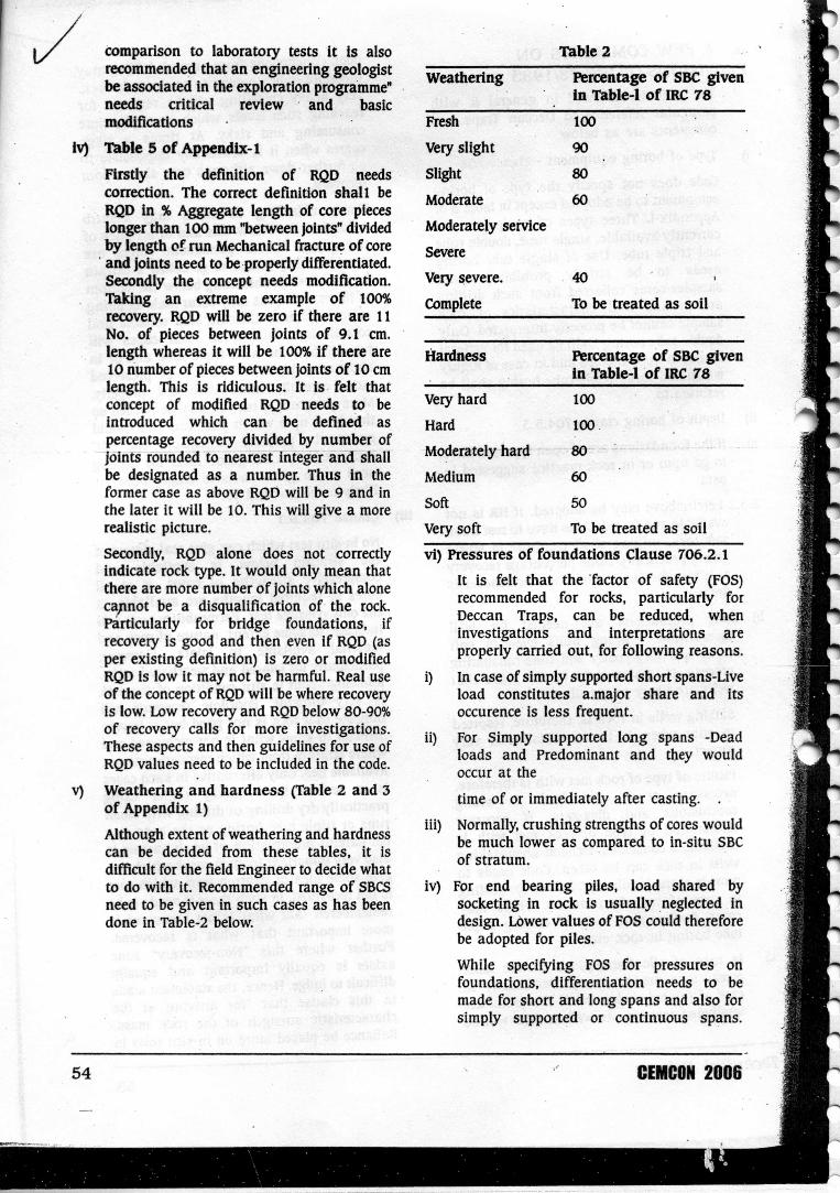
Although extent of weathering and hardnesscan be decided from these tables, it isdifficult for the field Engineer to decide whatto do with it. Recommended range of SBCSneed to be given in such cases as has beendone in Table-2 below.
Table 2
weathering Percentage of SBC givenIn Table-l of IRC 18
54
Fresh
Very slight
Slight
Moderate
Moderately service
Severe
Very severe.
Complete
100
90
80
60
·40
To be treated as soil
Hardness Percentage of SBC givenIn Table-l of IRC 18
Very hard
Hard
Moderately hard:
Medium
Soft
100
100 .
8()
60
50Very soft To be treated as soil
vi) Pressures of foundations Clause 706.2.1
It is felt that the factor of safety (FOS)recommended for rocks, particularly forDeccan Traps, can be reduced, wheninvestigations and interpretations areproperly carried out, for following reasons.
i) In case of simply supported short spans-Liveload constitutes a.major share and itsoccurence is less frequent.
ii) For Simply supported long spans -Deadloads and Predominant and they wouldoccur at the .
time of or immediately after casting.
iii) Normally, crushing strengths of cores wouldbe much lower as compared to in-situ SBeof stratum.· .
lv) For end bearing piles, load shared bysocketing in rock is usually neglected indesign. LOwervalues of FOS could thereforebe adopted for piles.
While specifying FOS for pressures onfoundations, differentiation needs to bemade for short and long spans and also forsimply supported or continuous spans.
CEMCON2006

Differentiation also needs to bemadedepending upon type of foundation such asopen, well or pile. The values given in codeare very conservative and need review.
vii) Scour
. No specific provision is made in codes (norsuch is possible) for scour in rocks. This istrue for both the conditions either when rockis exposed or when it is above thecalculated scour level considering actualbed material. A provision is always made inNI~ that scour shall be considered uptorock. This is very dangerous. The nature ofrock met-with needs to becarefully studiedand possibility of scour in it estimated.Foundation levels will then have to bedecided based on such estimation.
viii) Depth of Embedment (Clause 705.3.1)
The provisions in the earlier codes was thatin case of open foundations resting on softrock and in case of exposed rocks, depths ofembedment- shall be 1.5m and in 'case offoundations resting on hard rocksembedment shall be 0.60m. Provision madein "1983 edition of the code is more logicalthan above but still needs someclarification. Two questions arise. Firstly ifHR (ultimate compressive. strength> 100kg!$q.cm.) is overlaid with SR (u.c.s. > 20kg! sq .cm.) whether equivalence of SR canbe considered. This practice was adopted inMaharashtra P W D earlier. Secondly, whenfinal foundation is to be -R. whetherembedment of 0.6m is required.Irrespectiveof depth of SR. Following proposal is made.('5' indicates depth of SR an<;1 H indicatesdepths of emebedment in HR.)
If 5> 1.5m. H may be equal to zero i.e.foundation can rest on HR
If 15> S > 0.9. H = 1.5 - 5
If 0.9 > S H = 0.60m
5. SOME MORE CASE HISTORIES5.1 GHODDny tail channel bridge
The bridge was founded on hard compactbasalt with closely spaced columnar joints.During the very first flood columns of jointwashed away taking the bridge with them.The bridge thus got washed away althoughit was founded on hard rock because therock was jointed. Particularly in case ofexposed rocks. more care is thereforeneeded. Geological investigations need to be
carried out in case of important and major" bridges even if they are to be founded onexposed rocks.
5.2 Bridge at Chaskaman
A bridge on the tail channel of Chaskamandam was founded on hard compact basalt .The rock is jointed. More predominent ishorizontal set of joints. Along these jointsdeep weathering" or the rock has takenplaces. There is heavy percolation of wateralong these sheet joints. Due to this typicalgeological feamre, foundation rock gotcracked. uneven settlement had taken place.The bridge can not be used and is discarded.
From" the above two cases it can beconcluded that in jointed rocks, foundationlevels have to be more carefully determinedtaking into account the nature of jointing(Photo 6 & 7)
5.3 Mandve bridge
It is a major bridge across river .Mula inAhmednagar district. In the river bedamygdaloidal basalt is exposed. The pierswere to be founded on this rock. Normallythis rock being nearly unjointed is quietsuitable for foundation of a bridge, whenfresh. But there are" a large number of potholes in the river bed carved inamygdaloidal basalt due to river erosion.Some pot holes are more than a metre indiameter and are more than two to threemetres in depth. The wall of the rockseparating the two pot holes, in some casesis even less than 10 ems, As a matter ofcoincidence. at the time of inspection byengineer geologist at the pier location. acrowbar was struck on the exposed rocksurface and pot hole was found below, inwhich the entire crowbar disappeared. Aftercarrying correct investigations and correctinterpretation of the local geology thefoundations of two piers. were taken toabout 3 metres in rock because of theexistance of concealed pot holes. Thisindicates importance of surface geologicalsurveys and also importance ofunderstanding the geological featuresproperly and interpreting them correctly. Ifsuch systematic work would not have beendone then the bridge would have collapsed(Photo 8 & 9). .,.
Technical Volume 55

heterogeneous Codal provrsions moreparticularly applicable to these rocks needto be '&fafted. This will save costs and time.
6.3 All codes and specifications provide forinterpretation by engineering geologists.However, availability .. of property trained!.experienced geologist is scarce. The syllabiiin various engineering courses need to berecast and students need to be more exposedto field eonditions. Alternatively or inaddition, the engineers need to bespecifically trained for this purpose. Specialcourses need to be drafted and implemented.This is true for engineers from Govt.Department as well as consultants and
.contractors. Such training could be acriterion for promotion in case ofGovernment engineers and availability ofsuch trained engineers a prequalificationcriterion for consultants and contractors.Ibis needs to be done OJ! war tooting andbefore it is too late. Such trained 'engineerscould relieve the burden of available fewengineering geologists.
1 ACKNOWLEDGMENTSThe authors are indebted to Dr. RB. Gupte,Engineering Geologist, for his valuable guidanceand constant encouragements while writing thispaper. Authors are also thankful to: all theengineers incharge of Government Departnientsfor permitting us to make reference to the various
. .cases
8. REFERENCESi) IRC78/1983
ii) IS 4078/1980
iii) IS 5313/1980
iv) P.W.D. hand book of Government ofMaharashtra Part II Gupte RB.
v) Gupte RB., Karmarkar B.M., Kulkarni S.R &Marathe S.S. (1977) : The nature of DeccanTrap volcanicity in Western Maharashtra."Recent Researches in Geology (VoL4). acollection of papers in Honour of Prof G.W.Chiplunkar" Hindustan PublishingCorporation, Delhi.
•
Volume 51
,. \\..\