booster pump-techpart - 2of2 b
DESCRIPTION
LPG pump tender specificationTRANSCRIPT

HPCL
TENDER FORBAHADURGARH -TIKRIKALAN PIPELINE
STANDARD SPECIFICATIONSFOR LV INDUCTION MOTORS
Bid. No. 05/51/23LK/HPCL/024 R-1
MECON LIMITED
STANDARD SPECIFICATIONFOR
LOW VOLTAGE INDUCTIONMOTORS
MEC/S/05/E9/30
HPCL
TENDER FORBAHADURGARH -TIKRIKALAN PIPELINE
STANDARD SPECIFICATIONSFOR LOW VOLTAGE SC INDUCTION MOTORS
Bid. No. 05/51/23LK/HPCL/024 R-1
MECON LIMITED
Page 1 of 19
1.0 SCOPE
This specification covers the design, manufacture, testing, packing and supply of
three phase Low voltage squirrel cage induction motors.
2.0 CODES AND STANDARDS
2.1 The squirrel cage induction motors and their components shall comply with the latest
editions of following standards issued by BIS (Bureau of Indian Standards) unless
otherwise specified :
IS – 5 Colours for ready mixed paints and enamels.
IS – 325 Three phase induction motors.
IS – 1076 Preferred numbers.
IS – 1231 Dimensions of three phase foot mounted induction motors.
IS – 1271 Thermal evaluations and classification of electrical insulation.
IS – 2148 Flame proof enclosures of electrical apparatus.
IS – 2223 Dimensions of flange mounted AC Inductions motors.
IS – 2253 Designation for type of constructions and mounting arrangement of
rotating electrical machines.
IS – 2254 Dimensions of vertical shaft motors for pumps.
IS – 2968 Dimensions of slide rails for electric motors.
IS – 4029 Guide for testing three phase induction motors.
IS – 4691 Degrees of protection provided by enclosures for rotating electrical
machinery.
IS – 4722 Rotating electrical machines.
IS – 4728 Terminal marking and direction of rotation for rotating electrical
machinery.
IS – 4889 Method of determination of efficiency of rotating electrical machines.
IS – 6362 Designation of methods of cooling of rotating electrical machines.

HPCL
TENDER FORBAHADURGARH -TIKRIKALAN PIPELINE
STANDARD SPECIFICATIONSFOR LOW VOLTAGE SC INDUCTION MOTORS
Bid. No. 05/51/23LK/HPCL/024 R-1
MECON LIMITED
Page 2 of 19
IS – 6381 Construction and testing of electric apparatus with type of protection
IS – 7389 Pressurized enclosure of electrical equipment for use in hazardous
area.
IS – 7816 Guide for testing insulation resistance of rotating machines.
IS – 8223 Dimensions and output series for rotating electrical machines.
IS – 8289 Electrical equipment with type of protection ‘n’.
IS – 8789 Values of performance characteristics for three phase induction
motors.
IS – 9283 Motor for submersible pump sets.
IS – 9628 Three phase induction motors with type of protection ‘n’.
IS – 12065 Permissible limits of noise level for rotating electrical machines.
IS – 12075 Mechanical vibration of rotating Electrical Machines with shaft
heights 56 mm and higher – measurement, evaluation and limits of
vibration severity.
IS – 12802 Temperature rise measurement of rotating electrical machines.
IS – 12824 Type of duty and classes of rating assigned to rotating electrical
machines.
IS – 13408 Code of practice for the selection, installation and maintenance of
electrical apparatus for use in potentially explosive atmospheres.
IS – 13529 Guide on effects of unbalanced voltages on the performance of three
phase cage induction motors.
IS – 13555 Guide for selection and application of three phase induction motors for
different types of driven equipment.
IS – 14568 Dimensions and output series for rotating electrical machines, frame
numbers 355 to 1000 and flange numbers 1180 to 2360.

HPCL
TENDER FORBAHADURGARH -TIKRIKALAN PIPELINE
STANDARD SPECIFICATIONSFOR LOW VOLTAGE SC INDUCTION MOTORS
Bid. No. 05/51/23LK/HPCL/024 R-1
MECON LIMITED
Page 3 of 19
2.2 In case of imported motors, standards of the country shall be applicable if these
standards are equivalent or stringent than the applicable Indian Standards.
2.3 The motors shall also conform to the provisions of Indian Electricity rules and other
statutory regulations currently in force in the century.
2.4 In case Indian Standards are not available, standards issued by IEC / BS / VDE /
IEEE / NEMA or equivalent agency shall be applicable.
2.5 In case of any contraction between various referred standards / specifications / data
sheets and statutory regulations, the following order of priority shall govern :
- Statutory regulations
- Data sheets
- Job specifications
- This specifications
- Codes and standards
3.0 GENERAL REQUIREMENTS
3.1 The offered equipment shall be brand new with state of the art technology and proven
field track record. No prototype equipment shall be offered.
3.2 Vendor shall ensure availability of spare parts and maintenance support services for
the offered equipment at least for 15 years from the date of supply.
3.3 Vendor shall give a notice of at least one year to the end user of equipment before
phasing out the product / spares to ensure the end user for placement of order for
spares and services.

HPCL
TENDER FORBAHADURGARH -TIKRIKALAN PIPELINE
STANDARD SPECIFICATIONSFOR LOW VOLTAGE SC INDUCTION MOTORS
Bid. No. 05/51/23LK/HPCL/024 R-1
MECON LIMITED
Page 4 of 19
4.0 OPERATING CONDITIONS
4.1 Ambient Conditions
Motors shall be suitable for operating satisfactory in humid corrosive atmosphere
found in refineries, petrochemical, fertilizer and metallurgical plants. Service
conditions shall be as specified in the motor data sheet. If not specifically mentioned
therein, a design ambient temperature of 400C and an altitude not exceeding 1000 mtr
above mean sea level shall be taken into consideration.
4.2 Frequency and Voltage Variations
Unless otherwise agreed, motors shall be designed for continuous operation at rated
output under the following conditions :
a) The terminal voltage differing from its rated value by not more than +6% or
b) The frequency differing from its rated value by not more than the +3% or
c) Any combination of (a) and (b)
4.3 Starting
a) Unless otherwise specified, motor shall be designed for direct-on-line starting.
b) Motors shall be designed for re-acceleration under full load after a momentary
loss of voltage with the residual voltage being 100% and is in phase
opposition to the applied voltage.
c) Minimum locked rotor thermal withstand time at rated voltage shall be 10
seconds under cold conditions and 8 seconds under hot conditions. The
starting time of the motor shall be less than the hot thermal withstand time
(time tE in case of increased safety i.e. Ex-e motors) to permit application of

HPCL
TENDER FORBAHADURGARH -TIKRIKALAN PIPELINE
STANDARD SPECIFICATIONSFOR LOW VOLTAGE SC INDUCTION MOTORS
Bid. No. 05/51/23LK/HPCL/024 R-1
MECON LIMITED
Page 5 of 19
conventional bimetal relays or thermal release against locked rotor and
overload conditions.
d) Unless otherwise specified, all motors shall be suitable under specified load
conditions with 75% of the rated voltage at the motor terminals.
e) Motors shall be designed to allow the minimum number of consecutive starts
indicated in Table – I below :
TABLE – I
Starts Min. no. ofconsecutive starts
No. of consecutive start-ups with initial temp. ofthe motor at ambient level (cold)
3
No. of consecutive start-ups with initial temp. ofthe motor at full load operating level (hot).
2
4.4 Direction of Rotation
Motors shall be suitable for either direction of rotation. In case unidirectional fan is
provided for motors, direction of rotation for which the motor is designed shall be
permanently, indicated by means of an arrow. Directional arrow should be
manufactured from corrosion resistant material. when a motor is provided with bi-
directional fans, a double headed arrow should be provided.
5.0 PERFORMANCE
5.1 Motors shall be rated continuous duty (S1), unless otherwise specified.
5.2 Unless otherwise specified, the starting current (as % rated current) shall not exceed
600% subject to tolerance.

HPCL
TENDER FORBAHADURGARH -TIKRIKALAN PIPELINE
STANDARD SPECIFICATIONSFOR LOW VOLTAGE SC INDUCTION MOTORS
Bid. No. 05/51/23LK/HPCL/024 R-1
MECON LIMITED
Page 6 of 19
5.3 In particular cases, when the starting current is to be limited, care shall be taken such
that the design value of torque meets the load requirement while at the same time
complying to clause 4.3 above of this specification.
5.4 In particular cases, when the starting with reduced voltage is specified, care shall be
taken such that the design values of torque meets the load requirement while at the
same time complying to clause 4.3 above of this specification.
5.5 Starting torque and minimum torque of the motor shall be compatible with the speed
torque curve of the driven equipment under specified starting and operating
conditions.
For heavy duty drives as blowers, crushers etc. high starting torque motors shall be
provided.
In case where characteristics of driven equipment are not available while selecting the
motor, minimum starting torque shall be 110% of rated value for motors up to 75 KW
and shall be 90% of rated value for motors above 75 KW.
5.6 The pull out torque at the rated voltage shall be not less than 175 percent of the rated
load torque with no negative tolerance. Unless otherwise agreed, the pull out torque
shall not exceed 300 percent of the rated load torque.
In case of motors driving equipment with pulsating (e.g. reciprocating compressors)
the minimum value of pull out torque at 75 percent of the rated voltage shall be more
than the peak value of pulsating torque and the current pulsation shall be limited to
40%.
5.7 The minimum value for product of efficiency and power factors for motors rated up
to and including 37 KW shall be as per IS.
The minimum value for product of efficiency and power factors of 2 pole, 4-pole, and
HPCL
TENDER FORBAHADURGARH -TIKRIKALAN PIPELINE
STANDARD SPECIFICATIONSFOR LOW VOLTAGE SC INDUCTION MOTORS
Bid. No. 05/51/23LK/HPCL/024 R-1
MECON LIMITED
Page 7 of 19
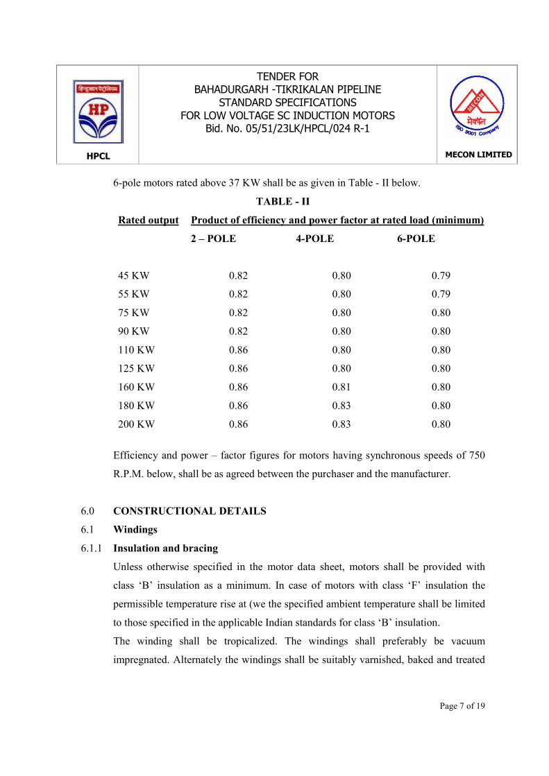
6-pole motors rated above 37 KW shall be as given in Table - II below.
TABLE - II
Rated output Product of efficiency and power factor at rated load (minimum)
2 – POLE 4-POLE 6-POLE
45 KW 0.82 0.80 0.79
55 KW 0.82 0.80 0.79
75 KW 0.82 0.80 0.80
90 KW 0.82 0.80 0.80
110 KW 0.86 0.80 0.80
125 KW 0.86 0.80 0.80
160 KW 0.86 0.81 0.80
180 KW 0.86 0.83 0.80
200 KW 0.86 0.83 0.80
Efficiency and power – factor figures for motors having synchronous speeds of 750
R.P.M. below, shall be as agreed between the purchaser and the manufacturer.
6.0 CONSTRUCTIONAL DETAILS
6.1 Windings
6.1.1 Insulation and bracing
Unless otherwise specified in the motor data sheet, motors shall be provided with
class ‘B’ insulation as a minimum. In case of motors with class ‘F’ insulation the
permissible temperature rise at (we the specified ambient temperature shall be limited
to those specified in the applicable Indian standards for class ‘B’ insulation.
The winding shall be tropicalized. The windings shall preferably be vacuum
impregnated. Alternately the windings shall be suitably varnished, baked and treated

HPCL
TENDER FORBAHADURGARH -TIKRIKALAN PIPELINE
STANDARD SPECIFICATIONSFOR LOW VOLTAGE SC INDUCTION MOTORS
Bid. No. 05/51/23LK/HPCL/024 R-1
MECON LIMITED
Page 8 of 19
with epoxy gel for operating satisfactorily in humid and corrosive atmospheres.
Windings shall be adequately braced to prevent any relative movement during
operation. In this respect, particular care shall be taken for the stator windings for
direct-an-line starting squirrel cage motors. Insulation shall be provided between coils
of different phases which lie together. Core laminations must be capable of
withstanding burnout for rewind at 400°C without damage or loosening.
In case of motors driving equipment with pulsating loads, special care shall he taken
for the joints of rotor bars and end rings to avoid premature failures due to induced
fatigue stresses.
6.1.2 Phase Connections
The windings shall be connected in delta. However, for motors rated 2.2 KW and
below, star connection may be accepted.
In case of motor with star-delta starting, the motor windings shall be fully insulated
delta connection.
6.1.3 Winding Terminations
The ends of the windings shall be brought out into a terminal box. These shall be
terminated by means of terminals mounted on an insulating base made of non-
hygroscopic and non-flammable material.
All motors shall be with six terminals and suitable links to connect them in star or in
delta except for motors rated up to and including 2.2 KW which may be accepted
with three terminals.
All terminals shall be thoroughly insulated from the frame with material resistant to
tracking.
Anti-loosening, anti-vibration type of terminals shall be provided in case of increased
safety (Type Ex-e) and non-sparking (Type Ex-n) motors.
HPCL
TENDER FORBAHADURGARH -TIKRIKALAN PIPELINE
STANDARD SPECIFICATIONSFOR LOW VOLTAGE SC INDUCTION MOTORS
Bid. No. 05/51/23LK/HPCL/024 R-1
MECON LIMITED
Page 9 of 19
6.1.4 Terminal Box and Cable Entries
Unless otherwise agreed, the terminal box shall be located on the right hand side as
viewed from the driving (coupling) end. However, for motors up to 3.7 KW, terminal
box located on top may he accepted. The terminal box shall be rotatable in steps of
900 to allow entry from any direction.
The terminal box shall be of robust construction and large enough to facilitate easy
connection of the cables. The terminal box shall be with necessary clearances,
creepage distances between live parts and between live parts to earth considering air
insulation and without any compound filling. Terminal box cover shall be provided
with handles to facilitate easy removal. However, for terminal box covers weighing
less than 5 kg., terminal box covers without handles can be accepted.
An adequately sized earth terminal shall be provided in the motor terminal box for
termination of the fourth core of specified cables.
The terminal box shall be provided with cables lugs and entries for suitable cable
gland corresponding to the size of the specified cable. Nickel plated brass (or
aluminum is specifically required), double compression type cable glands shall be
supplied along with the motor for the specified cable sizes.
Equipment and accessories provided shall conform to the hazardous area
classification and the environmental conditions as specified in the motor data sheet.
Unless otherwise specified, the terminals, cable lugs, terminal box, cable entries and
cable glands shall be suitable for the cables sizes as specified below in Table - III for
2 pole, 4 pole or 6 pole motors :

HPCL
TENDER FORBAHADURGARH -TIKRIKALAN PIPELINE
STANDARD SPECIFICATIONSFOR LOW VOLTAGE SC INDUCTION MOTORS
Bid. No. 05/51/23LK/HPCL/024 R-1
MECON LIMITED
Page 10 of 19
TABLE - III
Motor rating up to and including Size of phase conductor (mm2)
2.2 KW and below 4 Al. / 2.5 cu
3.7 KW 6 Al. / 4 cu
5.5 KW 10 Al. / 6 cu
7.5 KW 16 Al. / 6 cu
11.0 KW 25 Al. / 16 cu
15.0 KW 35 Al.
18.5 KW 50 Al.
22.0 KW 70 Al.
30.0 KW 95 Al.
37.0 KW 70 Al.
45.0 KW 95 Al.
55.0 KW 120 Al.
75.0 KW 185 Al.
90.0 KW 2 x 95 Al
110.0 KW 2 x 120 Al
125.0 KW / 132 KW 2 x 185 Al
160.0 KW 2 x 185 Al
180.0 KW 2 x 240 Al
200.0 KW 2 x 300 Al
Cable sizes for motors having synchronous speeds 750 RPM and below shall be as
agreed between the purchaser and manufacturer.
Cables used are of 650/1100 V grade Aluminum conductor, PVC insulated, PVE
extruded inner sheath, armoured with overall PVC sheath. However for cables up to
& including 16 mm2 cross-section cables used may be with copper or aluminum

HPCL
TENDER FORBAHADURGARH -TIKRIKALAN PIPELINE
STANDARD SPECIFICATIONSFOR LOW VOLTAGE SC INDUCTION MOTORS
Bid. No. 05/51/23LK/HPCL/024 R-1
MECON LIMITED
Page 11 of 19
conductor as indicated in the motor data sheet.
The terminal box shall be capable of withstanding internal short circuit conditions
without danger to personnel or plant from the emission of hot gases or flame or due to
excessive distortion or damage to the terminal enclosure.
6.1.5 Phase Marking
Appropriate phase markings as per IS shall be provided inside the terminal box. The
marking shall be non-removable and indelible.
6.2 Motor Casing and Type of Enclosure
Motors for use in sate areas shall be industrial type meeting the specified ambient
conditions, starting and operating requirements.
Motors for use in hazardous areas (Zone-l or Zone-2) shall have type of protection
Ex-d or Ex-e or Ex-n as specified in the motor data sheet and shall meet the
requirements of applicable Indian standards.
The minimum degree of motor enclosures including terminal boxes and bearing
housing shall be IP-55 as per IS.
Motors for outdoor use shall be suitable for installation and satisfactory operation
without any protective shelter or canopy. Motor casing shall be provided with a
suitable drain for removal of condensed moisture except incase of flameproof motors
(Type Ex-d).
Vertical motors with downward shaft shall be provided with suitable canopies
covering the motor fully. Vertical motors with upward shaft e.g. on fin-fan coolers,
shall be adequately protected, (such as cowls / canopies) against ingress of water into
the enclosure or the bearing housing even when standing still for long periods of time.
Motors designed to handle external thrust from the driven equipment shall be
HPCL
TENDER FORBAHADURGARH -TIKRIKALAN PIPELINE
STANDARD SPECIFICATIONSFOR LOW VOLTAGE SC INDUCTION MOTORS
Bid. No. 05/51/23LK/HPCL/024 R-1
MECON LIMITED
Page 12 of 19
supplied with a thrust bearing at the non-driving end.
All internal and external metallic parts, which may come into contact with cooling
air, shall be pf corrosion resistant material or appropriately treated to resist the
corrosive agents which may be present in the atmosphere. Screws and bolts shall be
of rust proof material or protected against corrosion.
Unless otherwise agreed, motors shall have standard frame sizes for various output
ratings as stipulated in IS.
6.3 Bearing and Lubrication
Motors shall have grease lubricated ball or roller bearings. In all cases, the bearings
shall be chosen to provide a minimum L-10 rating life of 5 years, (40, 000 hours) at
rated operating conditions (The L-10 rating life is the number of hours at constant
speed that 90% of a group of identical bearings will complete or exceed before the
first evidence of failure).
Unless otherwise specified, the bearings shall be adequate to absorb axial thrust
produced by the motor itself or due to shaft expansion.
Vertical motors shall be provided with thrust bearings suitable for the load imposed
by the driven equipment.
In cases such as pumps for hot liquids where the driven equipment operates at nigh
temperatures, bearings shall be cooled by a shaft mounted fan. This shall ensure
efficient ventilation of the bearing and disperse the heat transmitted from the driven
equipment by conduction or convection.
Bearings shall be capable of grease injection from outside without removal of covers
with mown; in the running conditions. The bearing boxes shall be provided with
necessary features to prevent loss of grease or entry of dust / moisture e.g. labyrinth
seal. Where grease nipples are provided, these shall be associated, where necessary,
HPCL
TENDER FORBAHADURGARH -TIKRIKALAN PIPELINE
STANDARD SPECIFICATIONSFOR LOW VOLTAGE SC INDUCTION MOTORS
Bid. No. 05/51/23LK/HPCL/024 R-1
MECON LIMITED
Page 13 of 19
with appropriately located relief devices which ensure passage of grease through the
bearings.
Pre-lubricated sealed bearings may be considered provided a full guarantee is give for
4 to 5 years of trouble-free service without the necessity of re-lubrication.
6.4 Cooling System
All motors shall be self ventilated, fan cooled. Fans shall be corrosion resistant or
appropriately protected. They shall be suitable for motor rotation in either direction
without affecting the performance of the motor. If this is not possible for large
outputs, it shall be possible to reverse the fan without affecting the balancing of the
motor.
For motors operating in hazardous area, the fans shall be of an anti-static non-
sparking material.
6.5 Rotor
The rotor shall be of squirrel cage type, dynamically balanced to provide a low
vibration level and long service life for the bearings. The accepted values of peak to
peak vibration amplitudes for a motor at rated voltage and speed on a machined
surface bedplate with the motor leveled and with a half-key or coupling fitted shall
not exceed those given in IS. Die cast aluminum rotors for motors in hazardous areas
may be accepted provided the same are type tested and approved by competent
authorities.
6.7 Shaft Extension
Motors shall be provided with a single shaft extension with key-way and full key.
Motor shaft shall be sized to withstand 10 times the rated design torque.
HPCL
TENDER FORBAHADURGARH -TIKRIKALAN PIPELINE
STANDARD SPECIFICATIONSFOR LOW VOLTAGE SC INDUCTION MOTORS
Bid. No. 05/51/23LK/HPCL/024 R-1
MECON LIMITED
Page 14 of 19
6.7 Lifting Hook
All motors weighing more than 30 kg shall be provided with lifting hooks of adequate
capacity.
6.8 Earth Terminals
Two earth terminals located preferably on diametrically opposite sides shall be
provided for each motor. The size of each earth stud shall be as given below in Table
– IV :
TABLE - IV
Motor Rating Stud Size
Upto and including 7.5 KW 6 mm
11 KW to 30 KW 10 mm
Above 37 KW 12 mm
Necessary nuts and spring washers shal1 be provided for earth connection.
An additional earth terminal shall be provided inside the terminal box as stated in
6.1.4.
7.0 MISCELLANEOUS ACCESSORIES
7.1 Anti-Condensation Heaters
All motors rated above 22 KW shall be provided with 240 V anti-condensation
heaters, sized and located so as to prevent condensation of moisture during shut-down
periods. Motors rated 22 KW and below shall be provided with anti-condensation
heaters only if specified in the motor data sheet. The heaters shal1 permanently
remain ‘ON’ when the motor is nor in service and as such shall not cause damage to
the windings.
For motors installed in hazardous atmospheres (zone - 1 or zone - 2), such heaters

HPCL
TENDER FORBAHADURGARH -TIKRIKALAN PIPELINE
STANDARD SPECIFICATIONSFOR LOW VOLTAGE SC INDUCTION MOTORS
Bid. No. 05/51/23LK/HPCL/024 R-1
MECON LIMITED
Page 15 of 19
shall conform to the-provisions of applicable Indian Standards and temperature
classified specified in the motor data sheet.
The heater leads shall be brought out to a separate terminal box of the same
specification and grade of protection as the main terminal box. The cable glands
provided shall be suitable for 2 x 4 sq. mm conductor \ armoured cable, unless
otherwise specified.
A warning label with indelible red inscription shall be provided on the motor to
indicate that the heater supply shall be isolated before carrying out any work on the
motor.
7.2 Name Plates
A- stainless steel-name plate manufactured from series 300 stainless steel and having
information as per IS shall be provided on each motor.
In addition to the motor rating plate, a separate motor plant equipment number plate
(i.e. motor tag number) shall be fixed in a readily visible position. This number shall
be as per the motor data sheets.
Additional information as stipulated in applicable Indian Standard shall be included
in the name plate for motors meant for use in hazardous atmospheres.
8.0 NOISE LEVEL
The permissible noise level shall nm exceed the stipulations laid in IS, unless
otherwise specified in the motor data sheet.
9.0 MOTOR VIBRATIONS
Motor vibrations shall be within the limits of IS, unless otherwise specified for the
driven equipment.

HPCL
TENDER FORBAHADURGARH -TIKRIKALAN PIPELINE
STANDARD SPECIFICATIONSFOR LOW VOLTAGE SC INDUCTION MOTORS
Bid. No. 05/51/23LK/HPCL/024 R-1
MECON LIMITED
Page 16 of 19
10.0 CRITICAL SPEEDS
Tile first actual critical speed of stiff rotors shall not be lower than 125% of the
synchronous speed, For flexible rotors this shall be between 60% and 80% of the
synchronous speed : the second actual critical speed shall be above 125% of the
synchronous speed.
11.0 PAINTING
Internal and external parts of the casing and all metal parts including the canopy
likely to come in contact with the surrounding air shall be protected with anti-acid
paint that will resist the specified environment conditions.
All external surfaces of the motor and its canopy shall be given a coat of epoxy based
paint.
Paint shade shall be 632 as per Indian Standard.
12.0 INSPECTION AND TESTING
12.1 During manufacturing of motors, the motors shall be subject to inspection by
Owner’s Inspection/Consultant or by agency authorised by the Owner. The
manufacturer shall provide all necessary information concerning the supply to
Owner's Inspector/ Consultant.
12.2 Type tests, if specified, all the routine tests and other acceptance tests shall be
witnessed by the Inspector. The manufacturer shall give prior notice of minimum 4
weeks to the Inspector for witnessing the tests.
12.3 All tests shall be carried out at manufacturer’s shop under his care and expense.
12.4 Tests certificates duly signed by the Owner's Inspector/ Consultant shall be a pan of
final documentation.
12.5 The manufacturer shall submit ail internal test records of the test carried out by him

HPCL
TENDER FORBAHADURGARH -TIKRIKALAN PIPELINE
STANDARD SPECIFICATIONSFOR LOW VOLTAGE SC INDUCTION MOTORS
Bid. No. 05/51/23LK/HPCL/024 R-1
MECON LIMITED
Page 17 of 19
on the bought-out items, motor sub-assembly and complete motor assembly to the
Inspector before offering the motors for final inspection and testing.
12.6 The manufacturer shall periodically carry out the following type tests as per
applicable Indian Standards for all the frame sizes and ratings of motors.
(a) Full load test and measurement of voltage, current, power & slip
(b) Measurement of starting torque, starting current full load torque pull out
torque.
(c) Measurement of efficiency and p.f. at 100%, 75% and 50% load
(d) Temperature rise test
(e) Momentary overload test
(f) Measurement of vibration
(g) Measurement of noise level
(h) Overspeed test
The above tests must be witnessed and approved by reputed inspection agencies, The
manufacture shall maintain test records and submit to the Owner's Inspector/
Consultant at the time of the final inspection & testing.
In special cases where the type tests are asked to be carried out, these shall be
witnessed by the Owner’s Inspector/ Consultant
12.7 The manufacturer shall carry out routine tests as per applicable Indian Standards on
all the motors. Routine tests nor limited to the following shall form part of acceptance
testing :
(a) General visual checks, name plate details, mounting, terminal box location
and cable gland sizes.

HPCL
TENDER FORBAHADURGARH -TIKRIKALAN PIPELINE
STANDARD SPECIFICATIONSFOR LOW VOLTAGE SC INDUCTION MOTORS
Bid. No. 05/51/23LK/HPCL/024 R-1
MECON LIMITED
Page 18 of 19
(b) Measurement of shaft centre height dimensions
(c) Measurement of clearances in the terminal box
(d) Verification of type of terminals ( for Ex-e & Ex-n motors)
(e) Verification of direction of rotation
(f) Measurement of winding resistance
(g) Insulation resistance rest (before & after high voltage test)
(h) High voltage test
(i) No load test and measurement of voltage, speed, current & power input
(j) Locked rotor test at reduced voltage and measurement of voltage current &
power input
(k) Reduced voltage starting & running
12.8 The manufacturer shall submit the following certificates for verification by the
Owner’s Inspector/Consultant :
(a) Test certificate for degree of protection of enclosure
(b) Test certificates issued by the recognised independent test house for hazardous
area motors
(c) Approval certificates issued by Statutory Authorities for hazardous area
motors
(d) BIS license as required by Statutory Authorities for Ex-d motors
12.9 Though the motors shall be accepted on the basis of the satisfactory result of the
testing at the shop, it shall not absolve the Vendor from liability regarding the proper
functioning of the motors coupled to the driven equipment at site.
13.0 CERTIFICATION
The hazardous area motors and associated equipment shall have test certificates

HPCL
TENDER FORBAHADURGARH -TIKRIKALAN PIPELINE
STANDARD SPECIFICATIONSFOR LOW VOLTAGE SC INDUCTION MOTORS
Bid. No. 05/51/23LK/HPCL/024 R-1
MECON LIMITED
Page 19 of 19
issued by recognised independent test house (CMRI / BASEEFA / LCIE / UL / FM or
equivalent). All indigenous motors shall conform to Indian Standards and shall be
certified by Indian testing agencies. All motors (indigenous & imported) shall also
have valid statutory approvals as applicable for the specified location. All indigenous
flameproof motors shall have valid BIS license & marking as required by statutory
authorities.
14.0 PACKING AND DESPATCH
All the equipment shall be divided into several sections for protection and ease of
handling during transportation. The equipment shall be properly packed for
transportation by ship / rail or trailer. The equipment shall be wrapped in polythene
sheets before being placed in crates / cases to prevent damage to the finish. Crates /
cases shall have skid bottom for handling. Special notations such as ‘Fragile’, ‘This
side up’, ‘Centre of gravity’, ‘Weight’, ‘Owner’s particulars’. ‘PO Nos.’ etc. shall be
clearly marked on the package together with other details as per purchaser order.
The equipment may be stored outdoors for long periods before installation. The
packing shall be completely suitable for outdoor storage in areas with heavy rains /
high ambient temperature, unless otherwise agreed.

HPCL
TENDER FORBAHADURGARH -TIKRIKALAN PIPELINE
STANDARD SPECIFICATIONLV VARIABLE FREQUENCY DRIVE
Bid. No. 05/51/23LK/HPCL/024 R-1
MECON LIMITED
STANDARD SPECIFICATIONFOR
LV VARIABLE FREQUENCY DRIVESYSTEM
MEC/S/05/E9/ 33
HPCL
TENDER FORBAHADURGARH -TIKRIKALAN PIPELINE
STANDARD SPECIFICATIONLV VARIABLE FREQUENCY DRIVESBid. No. 05/51/23LK/HPCL/024 R-1
MECON LIMITED
1 of 17
1.0 SCOPEThe scope of this specification is to define the minimum technical requirements forthe design, manufacture, testing and supply of Low Voltage, AC Variable FrequencyDrive (VFD) System. The VFD shall be complete with Squirrel Cage InductionMotor (if specified in data sheet), Converter, Converter transformer (if required), AC/ DC link reactor with associated auxiliaries and local panel.
The Vendor shall be responsible for engineering and functioning of the completesystem, meeting the intent and requirement of this specification and data sheets.
In this specification, the word ‘drive’ shall refer to the power and control module(rectifier-inverter-controller system) along with the associated electrical such as AC /DC link reactor, tilters, contactors and other auxiliary panel components / circuitry.The word ‘system’ shall refer to all of the above and the associated motor and localpanel put together.
This specification applies to drives connected to line voltage up to 1000 V. AC.
2.0 CODES AND STANDARDSThe equipment shall comply with the requirements of latest revision of followingstandards issued by BIS (Bureau of Indian Standards), unless otherwise specified.
IS-5 Colours for ready mixed paints and enamelsIS – 325 Three phase induction motorsIS – 3700 Essential ratings and characteristic of semi-conductor devicesIS – 3715 Letter symbols for semi-conducting devicesIS – 4237 General requirement of switchgear & control gear for voltage not
exceeding 1000 V.IS – 4411 Code of designation of semi-conducting devices.IS – 5001 Guide for preparation of drawings for semi-conductor devices.IS – 5469 Code of practice for the use of semi-conductor junction devices.IS – 8789 Performance parameters for motorsIS – 13947 Low voltage switchgear and control gear: General rules
2.2 In case of imported equipment, standards of the country of origin shall be applicable,if these standards are equivalent or stringent than the applicable Indian standards.
2.3 The equipment shall also conform to the provisions of Indian Electricity rules andother statutory regulations currently in force in the country.

HPCL
TENDER FORBAHADURGARH -TIKRIKALAN PIPELINE
STANDARD SPECIFICATIONLV VARIABLE FREQUENCY DRIVESBid. No. 05/51/23LK/HPCL/024 R-1
MECON LIMITED
2 of 17
2.4 In case Indian standards are not available for any equipment. standards issued by IEC/ BS / VDE / IEEE / NEMA or equivalent agency shall be applicable.
2.5 In case of any contradiction between various referred standards / specifications / datasheet and statutory regulations the following order of priority shall govern :
- Statutory regulations- Data sheets- Job specification- This specification- Codes and standards
3.0 SITE CONDITIONS3.1 The AC drive system shall be designed to operate under specified site conditions as
specified in the data sheets. If not specifically mentioned therein, a design ambienttemperature of 40°C and an altitude not exceeding 1000 metres above mean sea levelshall be considered.
3.2 The AC drive shall be installed indoors in a non-hazardous, air-conditioned orpressurised room, as specified in data sheet.
3.3 All the equipment shall be designed for continuous duty as per nameplate ratingunder the specified ambient conditions.
4.0 GENERAL REQUIREMENTS4.1 The offered equipment shall be brand new with state of art technology and proven
field track record. No prototype equipment shall be offered.
4.2 Vendor shall ensure availability of spare parts and maintenance support services forthe offered equipment for at least for 15 years from the date of supply.
4.3 Vendor shall give a notice of at least one year to the end user of equipment andMECON before phasing out the product / spares to enable the end user for placementof order for spares and services.
5.0 TECHNICAL REQUIREMENT5.1 Performance Requirement5.1.1 The system shall be energy efficient, and shall provide very high reliability, high
power factor, low harmonic distortion and low vibration / wear / noise. It shall beeasy to install in minimum time and expense and no special tools shall be required for
HPCL
TENDER FORBAHADURGARH -TIKRIKALAN PIPELINE
STANDARD SPECIFICATIONLV VARIABLE FREQUENCY DRIVESBid. No. 05/51/23LK/HPCL/024 R-1
MECON LIMITED
3 of 17
routine maintenance.
5.1.2 The system shall be designed to deliver the motor input current and torque for thecomplete speed torque characteristics of the load, with input supply variation of+10% and frequency variation of +3%. The system shall be suitable for the loadcharacteristics and the operational duty of the-driven equipment. It shall be capable ofwithstanding the tl1ermal and dynamic stresses and the transient mechanical torque,resulting from short circuit.
5.1.3 The drive system shall be designed to operate in one or more of the followingoperation modes as specified in the data sheet:
a) Variable torque changing as a function of speed i.e. Speed squaredb) Constant torque over a specific speed rangec) Constant power over a specific speed range where the torque decrease when
speed increasesd) Any other as specified in data sheet
5.1.4 The drive controller shall be equipped with microprocessor based digital regulatorwith progranm1able functions. The power control regulator logic shall provide foracceleration/deceleration current limit curve and shall be capable of field adjustmentswithout shutting the system down. Linear acceleration and deceleration shall beseparately programmable from 0.1 to 20 seconds.
5.1.5 The System shall be suitable for single quadrant operation and the speed variationshall be with range 1: 100 unless otherwise specified with speed set accuracy of +1%of rated maximum Speed and steady state regulation of +0.5% of rated speed.
5.1.6 The total harmonic distortion (THD) of the voltage and current at inverter output shallbe as per IEC 61800 and same shall be considered in the design of the motor.
5.1.7 Harmonic at the supply side of the drive system at PCC (point of common coupling)shall be restricted within the maximum allowable levels of current and voltagedistortion as per recommendations of the latest edition of IEEE-519.
5.1.8 The controller output overload capacity shall be 150% of rated current of motor forone minute for constant torque applications, and 115% of rated current for one minutefor variable torque applications at rated voltage. If the motor load exceeds the limit,the drive shall automatically reduce the frequency and voltage to the motor to guardagainst overload. If load demands exceeds the current limit for more than 1 minute,
HPCL
TENDER FORBAHADURGARH -TIKRIKALAN PIPELINE
STANDARD SPECIFICATIONLV VARIABLE FREQUENCY DRIVESBid. No. 05/51/23LK/HPCL/024 R-1
MECON LIMITED
4 of 17
the drive shall shut down to prevent over heating of the motor and damage to thedrive.
5.1.9 During operation the system shall be capable of developing sufficient torque under allload conditions to respond to a 20% alteration in set point within a time limit up to 60seconds.
5.1.10 The integrator action of the set point alteration shall be independently adjustable forboth an upward and a downward alteration. The minimum time interval between setpoint adjustment by the distributed control system shall be considered as 10 seconds.
5.1.11 Drive shall trip in case the speed exceeds 105 %of the maximum operational speedand / or reduces to 95% of the minimum operational speed for more than 10 seconds.
5.1.12 Maximum noise level from the drive at 1 meter distance, under rated load with allNormal cooling fans operating shall not exceed 75 dB (A).
5.1.13 Variable frequency drive shall be arranged so that it can be operated in an open circuitmode, disconnected from the motor for start up adjustments and troubleshooting.
5.2 Control Requirement5.2.1 The system shall operate on constant V / f supply with required voltage boost
capability in low frequency mode of operation.
5.2.2 Short time voltage dips up to 80% of nominal (e.g. in case of a larger motor start upconnected to the same bus as VFD), shall not cause the control system to stopfunctioning and shall not trip the drive system.
5.2.3 The system shall also be equipped with a facility which will restart the system in caseof voltage dip over 20% or power interruptions for less than 2 seconds, with recoveryof the voltage to its nominal value. The drive shall have the facility to block thisfeature, if required by the operator. Upon restart, the convener shall be capable ofsynchronizing onto a rotating motor and develop full acceleration torque within 10seconds.
5.2.4 The system shall be suitable for number of starts as per the specification for MediumVoltage Induction Motors.
5.2.5 The power controller shall be regulated to always start the motor in the forwarddirection. Logic shall be provided to prevent the motor from being started in the
HPCL
TENDER FORBAHADURGARH -TIKRIKALAN PIPELINE
STANDARD SPECIFICATIONLV VARIABLE FREQUENCY DRIVESBid. No. 05/51/23LK/HPCL/024 R-1
MECON LIMITED
5 of 17
reverse direction.
5.2.6 The drive motor shall be speed regulated corresponding 10 4-20 mA or 0-10 Vreference input signal. Upon complete {ass of the user's speed reference signal, thedrive shall automatically run at constant speed as determined by the last speedreference available prior to the loss of signal.
5.2.7 It shall be possible to vary the speed of the drive in either manual or auto mode.Auto/manual selection shall be from VFD panel unless otherwise specified.a) With the selector switch in “manual” mode, the operator shall be able to set
the speed through key pad (mounted on front of the drive panel) or from speedincrease / decrease push buttons (from the field). Motor operatedpotentiometer shall be provided as a speed set point device.
b) With the selector switch in “auto” mode, speed of the motor shall becontrolled from a 4-20 mA signal, from owner’s PLC / DCS (Process Control)system. Necessary equipment required for interfacing with PLC / DCS shallalso be provided in the VSD panel.
5.2.8 The required provision for the interface with PLC / DCS (located at remote controlroom) including the details of communication module and data transfer facility, I/Odetails shall be furnished. The communication interface shall be via serialcommunication link with industry standard open protocol i.e. MODBUS / DataHighway Plus / RS-485 etc. and same shall be coordinated with the interfacingequipment. In case the vendor is using their proprietary software, the interfacesoftware for use with owner’s system (software) shall be provided.
5.3 Panel Construction5.3.1 The panel shall include suitable isolating device (i.e. Circuit breaker / MCCB /
Switch fuse) for main supply, contactors, semi conducting power devices (Diodes /IGBT) modules with protective devices, reactors, filters, output isolating device,control circuit control accessories, indication and annunciation etc.
5.3.2 Main isolating device shall function as a manual disconnect and shall be an AC thethermal magnetic circuit breaker or a fused switch with dual element fuse to tripautomatically on fault currents, as specified in data sheet. Devices shall be lockable inthe open position and shall have a minimum interrupting capacity as specified in datasheet. Interlock shall be provided between the door, so that door cannot be openedunless the breaker is open.

HPCL
TENDER FORBAHADURGARH -TIKRIKALAN PIPELINE
STANDARD SPECIFICATIONLV VARIABLE FREQUENCY DRIVESBid. No. 05/51/23LK/HPCL/024 R-1
MECON LIMITED
6 of 17
5.3.3 The drive shall be suitably housed in sheet steel panels and shall be fabricated with 2mm hick cold rolled sheet steel The panel shall be suitable for indoor installation, ifnot otherwise specified. The panel shall be free standing with degree of protection asIP-41. The maximum and minimum operating height shall be 1800 mm and 300 mmrespectively.
5.3.4 Bolted undrilled gland plate shall be provided at bottom with double compressiontype cable gland. Clamp type terminals shall be used for connection of all wires up to10 mm2 and terminal for higher sizes shall be bolted type suitable for cable lugs.Minimum space for power cable termination shall be 200mm clear.
5.3.5 Bus bars shall be of electrolytic copper, color coded. All the live parts shall besleeved / shrouded to ensure complete safety to personnel intending to carry outroutine inspection by opening the panel doors. All the ‘equipment inside’ the paneland on the doors shall be provided with suitable nameplate. All wires shall be ferruledand terminals shall be properly numbered, minimum 20% spare terminal shall beprovided.
5.3.6 All the power and control switches shall be mounted on the door and shall beoperable externally. All the analogue instruments, where provided, shall be switchboard type, back connected, 72 x 72mm. Scale shall have red mark indicatingmaximum permissible operating rating.
5.3.7 Each panel shall be provided with illuminating lamp / 11 W CFL with switch andfuse. 5 / 15A, 240V power socket with switch and fuse shall be provided. Each panelshall have space heater with switch fuse and variable setting thermostat.
5.3.8 Copper earth bus of min. 30X6 mm size shall be provided at the bottom of the panelextending outside the pane on both sides. All the non-metallic components / partsshall be connected to the main earth bus bar. In case a separate earth bus forelectronic control system is required, the same shall be detailed in the offer.
5.3.9 All the metal parts shall be treated so as to ensure efficient anti-corrosive protection.Hard wares shall be zinc-passivated or electro galvanised. Panel enclosure andstructure supports shall be thoroughly cleaned and degreased to remove mill scale andrust etc. External surface shall be prepared for final painting of shade specified in datasheet.
5.3.10 All panels shall be of same height so as to form a uniform line-up, to give goodaesthetic appearance.

HPCL
TENDER FORBAHADURGARH -TIKRIKALAN PIPELINE
STANDARD SPECIFICATIONLV VARIABLE FREQUENCY DRIVESBid. No. 05/51/23LK/HPCL/024 R-1
MECON LIMITED
7 of 17
5.3.11 All the control wiring shall be enclosed in plastic channel. Each wire shall beidentified at both ends by self-sticking wire marker tapes or PVC ferrules. Power andcontrol wiring inside the panel shall be done with BIS approved, PVC insulated, fireretardant, copper conductor wire. 1.5 mm2 size wire shall normally be used providedthe control fuse rating is 10 Amps or less and 2.5 mm2 size for control fuse ratingabove 16 A for electrical circuits and 0.7 mm2 for electronic circuits.
5.3.12 All electronic modules and components shall be accessible from front of panel only.Modular plug-in/draw-out assemblies for both the system control electronicequipment and power electronic equipments shall be used.
5.3.13 Suitable removable type hooks shall be provided for lifting the panel.
5.4 Cooling5.4.1 Cooling system shall include well-dimensioned panel, adequate cooling airflow path,
Module cooling fan and if necessary, panel cooling fan. Vendor shall ensure that thepanel dimensions and flow paths have been designed for continuous running at thespecified ambient without overheating. For fan cooled drives, redundant ventilatingram shall be provided.
5.5 Equipment / Component Specification5.5.1 Motor
The motor shall be designed, constructed and tested in accordance with theSpecification for Low Voltage Induction Motor, in addition to the followingrequirements :
a) The motor shall be suitable for operation with a solid state power supplyconsisting of an adjustable frequency inverter for speed control.
b) The motor shall be suitable for the current waveforms produced by the powersupply including the harmonics generated by the drive.
c) The motor shall be designed to operate continuously at any speed over therange (1-100 %) of rated speed or as specified in data sheet.
d) Motor shall be provided with thermistor type temperature detector.
e) The motors shall be provided with Class ‘F’ insulation with temperature rise
HPCL
TENDER FORBAHADURGARH -TIKRIKALAN PIPELINE
STANDARD SPECIFICATIONLV VARIABLE FREQUENCY DRIVESBid. No. 05/51/23LK/HPCL/024 R-1
MECON LIMITED
8 of 17
limited to Class ‘B’.
f) The permitted voltage variation should take into account the steady statevoltage drop across the AC drive.
g) Motors required to be transferred to DOL by-pass mode shall be rated forspecified variations in line voltage and frequency.
h) The motor shall be constructed to withstand torque pulsations resulting fromharmonics generated by the solid state power supply.
i) The motor insulation shall be designed to accept the applied voltage waveform within the V peak and dv/ dt limits as per IEC-61800-2.
j) The drive manufacturer shall be solely responsible for proper selection of themotor for the given load application and the output characteristics of the drive.
k) Induced voltage at the shaft end of the motor at no load shall not exceed 250mV rms for roller and ball bearings and 400 mV for sleeve bearings. The nondriving end bearing shall be insulated from the motor frame to avoidcirculating current. The insulated bearing end shield or pedestal shall bear aprominent warning.
5.5.2 Converter Transformer
The converter transformer shall be oil filled or dry type as specified in data sheet, andshall be as per enclosed Specifications. The impedances of transformers with twosecondary windings for 12 pulse systems shall be selected to ensure equal load /current sharing between the two secondary windings, the converters and the motorwindings under all operational conditions including starting and restarting. Thetransformer shall be provided with +5% off circuit taps insteps of +2.5%.
5.5.3 Power Converter
a) The static power converter shall consist of a line side power converter foroperation as a rectifier and a load side power converter for operation as a fullycontrolled inverter.
b) Normally, for all output short circuits, the inverter shall interrupt the currentbefore any semi-conductor fuse blows. For internal short circuits, semi-

HPCL
TENDER FORBAHADURGARH -TIKRIKALAN PIPELINE
STANDARD SPECIFICATIONLV VARIABLE FREQUENCY DRIVESBid. No. 05/51/23LK/HPCL/024 R-1
MECON LIMITED
9 of 17
conductor fuse protection shall be provided, and for faults upstream of semi-conductor fuses, the converter shall be able to withstand a three-phase shortcircuit current until interrupted by normal breaker operation. In case of fuseless design, the failure shall be limited to the particular device, withoutcausing any damage to other parts of the power module. There must be clearannunciation of the failure of the device.
c) All power converter devices shall include co-ordination by peak voltageprotecting snubber networks and di / dt and dv / dt networks.
d) The current rating of the converter's semi-conductor components shall not beless than 120% of the nominal current flowing through the elements at fullload of the VFD through the whole speed range.
e) All power diodes shall be of silicon type with minimum VBO rating as 2.5times the rated operating voltage.
f) The power converter circuit shall be designed so that motor can be powered atits full name plate rating continuously without exceeding its rated temperaturerise due to harmonic currents generated by the inverter operation.
g) The conversion devices and associated heat sinks shall be assembled such thatindividual devices can be replaced without requiring the use of any specialprecautions/tools.
h) The cooling system of the electronic components, if provided, shall bemonitored and necessary alarms shall be provided to prevent anyconsequential damage to the power control devices.
i) All the power transistors, thyristors and diodes shall be protected with high-speed semiconductor grade fuse. Pt particulars of the power controller devicesand the fuses shall be properly co-ordinated for the selection of fuses.
5.5.4 DC Link / AC line Reactor
a) Smoothing reactors for the DC link shall be designed to sufficiently decouplethe rectifier and inverter portion of the converter and to limit fault currents inthis circuit. AC line reactors, if provided as per standard vendor design, shallbe suitable for harmonic suppression and fault current limitation.

HPCL
TENDER FORBAHADURGARH -TIKRIKALAN PIPELINE
STANDARD SPECIFICATIONLV VARIABLE FREQUENCY DRIVESBid. No. 05/51/23LK/HPCL/024 R-1
MECON LIMITED
10 of 17
b) The reactor shall be dry type, air cooled or fan cooled type located within thepanel. In case of fan cooled type, operation of fans shall be monitored.
c) Reactor shall be suitable for operation with the non-sinusoidal current waveshapes and DC components under all operational conditions of the systemwithout exceeding its temperature limits.
5.5.5 Output filter
VFD output current waveform shall be inherently sinusoidal at all speeds, withharmonic limits as per Cl. 5.1.6. Output filter capacitors shall be provided withdischarge circuit ensure that all residual stored charge is reduced to less than 50 V DCwithin 60 seconds after a loss of AC voltage.
The VFD system shall inherently protect motor from high voltage dv / dt stress.independent of cable length to motor. Output filter shall be an integral part of the VFD system and included within the VFD enclosure.
5.5.6 Bypass Feature
a) Bypass feature shall be provided, if specified in the data sheet.
b) All Variable frequency drives (VFD) having bypass feature shall have motorprotection relay along with necessary control and metering etc. Threecontractors / breakers shall be used for this purpose, one contactor in thebypass and two contactors across the drive, such that in case of drive mal-operation, the motor could be taken on bypass control, while the drive couldbe attended by opening its contactors.
c) Bypass feature shall meet the requirement of Type-2 coordination.
5.5.7 Output contactor / Load Break Switch
Output contactor / Load Break Switch shall be provided to provide isolation betweenthe output of the controller and the motor, if specified in the data sheet. The outputcontractor will be energized before speed signal is applied to the motor and will de-energise after the motor has. stopped.
5.5.8 Local Control Station

HPCL
TENDER FORBAHADURGARH -TIKRIKALAN PIPELINE
STANDARD SPECIFICATIONLV VARIABLE FREQUENCY DRIVESBid. No. 05/51/23LK/HPCL/024 R-1
MECON LIMITED
11 of 17
The local control station shall conform to the attached specifications.
Meters in the local control station shall be suitable for 4-20mA transducer outputs andshall be calibrated for the actual motor current. Further for drives with bypass facility,the meters shall be capable of reading bypass full load and starting currents, as well asthe drive current.
Requirement of controls and indications required in the Local Control Station shall beas specified in the data sheet.
5.6 Protection, Control, Metering and Indication / Annunciation
5.6.1 The manufacturer shall provide all the necessary system control, protection, alarmequipment and metering for the entire drive system and its auxiliary equipment.
5.6.2 Automatic sequence control shall include start-up of cooling system, interlockchecking, automatic start and run-up of drive, planned and emergency shutdown. Thesame shall be processed through microprocessor based system.
5.6.3 Operator Control Panel
Each drive shall be equipped with a mounted operator control panel consisting of abacklit alphanumeric display and a keypad with keys for Run / Stop, Local / Remote,Increase / Decrease, menu navigation and parameter select / save. All parameternames, fault messages, warnings and other information shall be displayed inComplete English words or standard English abbreviations to allow the user tounderstand what is being displayed without the use of a manual or cross-referencetable. This shall also be used for parameters, application and activity function access,fault, local control, adjustment storage, self test and diagnostics.
5.6.4 Protective Feature
The system offered shall incorporate protective features, properly coordinated for thedrive control and for motor but not limited to the following :
i) Incoming line surge protectionii) Under / Over voltage protectioniii) Phase loss, phase reversal protectioniv) Programmable Over current protectionv) Inverter Fault
HPCL
TENDER FORBAHADURGARH -TIKRIKALAN PIPELINE
STANDARD SPECIFICATIONLV VARIABLE FREQUENCY DRIVESBid. No. 05/51/23LK/HPCL/024 R-1
MECON LIMITED
12 of 17
vi) Over frequency operationvii) DC Line over voltageviii) Ventilation lossix) Over temperature of equipmentx) Over speed of motorxi) Specific motor protectionxii) System Earth fault Protection
5.6.5 Alarms
The system shall incorporate protection alarms, required for various fault conditions,for the Drive motor, Supply cables, Converter Transformer, DC Reactor and theConverter Alarms shall also be included for the failure of various auxiliaries togetherwith identification of the failing unit, loss of cooling system, various protectiondevices provided for converter transformer etc.
5.6.6 Control
The following controls shall be provided as a part of the Operator Control Panel orthrough separate switches.
i) Start / Stopii) Speed control (Raise / lower).iii) Forward / Reverseiv) Auto / Manual modev) Local / remotevi) Emergency stopvii) Start / stop for by pass starterviii) Trip – Remote Breaker
5.6.7 Indications
The following indications shall be provided as a part of the Operator Control panel.
i) Motor runningii) Motor stoppediii) VSD system fault

HPCL
TENDER FORBAHADURGARH -TIKRIKALAN PIPELINE
STANDARD SPECIFICATIONLV VARIABLE FREQUENCY DRIVESBid. No. 05/51/23LK/HPCL/024 R-1
MECON LIMITED
13 of 17
iv) System ready to startv) AC mains ONvi) Motor over speedvii) Rectifier output ‘ON’viii) Motor zero speedix) Remote breaker trip
Potential free contracts of items i) – iv) shall be wired separately for indications inDCS system.
5.6.8 Metering
Digital display of the following parameters shall be a part of the Operator ControlPanel, selectable by the operator.
i) Input AC Voltageii) Input AC frequencyiii) Input AC Currentiv) Output voltagev) Output current VSD / Bypassvi) Output frequencyvii) Motor thermal stateviii) Drive thermal stateix) Motor speedx) Motor energy meterxi) DC Link voltagexii) Hour Run
Necessary transducer shall be provided with 4-20mA output for indicating motorspeed and motor current in DCS.
5.6.9 Annunciations
Potential free contracts shall be provided for following annunciations and shall bewired up to terminal block for owner’s use for remote monitoring :
i) Rectifier fuse failureii) Main AC failureiii) Inverter fuse failureiv) Inverter overload
HPCL
TENDER FORBAHADURGARH -TIKRIKALAN PIPELINE
STANDARD SPECIFICATIONLV VARIABLE FREQUENCY DRIVESBid. No. 05/51/23LK/HPCL/024 R-1
MECON LIMITED
14 of 17
v) Inverter high temperaturevi) Failure of panel cooling systemvii) Motor failed to start
5.7 Fault Diagnostic
Fault diagnostic shall be built into the system to supervise the operation and failure ofthe system. The information regarding failure of any of the system including shutdown of the system shall be available for a period of minimum 4 days (96 hours) aftera shut down even through no supply would be available to the system. The systemmay be totally de-energised for maintenance or otherwise. It shall be possible toretrieve the record of events prior to tripping of the system or de-energisation.Auxiliary supply to the system components or to the electronics (firmware) for thediagnostics / display shall be taken care by the manufacturer for this purpose.
5.8 External Control Circuit
Control supply for devices external to VFD module i.e. contractor control, spaceheater supply for Motor / VFD, indicating lamps etc. shall operate on 240 voltscontrol power derived from single-phase control supply transformer, with switch-fuseprovided in primary and MCB in secondary, located inside the drive controller.
5.9 Reliability Features
i) The expected life time of the VFD shall be 20years. The VFD including allindividual components forming part of the system shall have an availability ofminimum 0.997 and a minimum MTBF of 4 years.
ii) The controller design shall incorporate the following reliability features:
- Pre-tested components with power components to be 100% tested underdynamic conditions.
- Printed circuit boards shall be computer tested and adjusted.- Printed circuit boards shall be temperature cycled for a minimum of 40 hours.- Printed circuit boards shall be treated for tropical, humid and corrosive
environment.
5.10 Maintenance features
The controller design shall incorporate the following maintenance features :

HPCL
TENDER FORBAHADURGARH -TIKRIKALAN PIPELINE
STANDARD SPECIFICATIONLV VARIABLE FREQUENCY DRIVESBid. No. 05/51/23LK/HPCL/024 R-1
MECON LIMITED
15 of 17
- Modular construction- Printed circuit boards shall be plug connected.- All components shall be easily accessible from the front of the enclosure.- Standard diagnostics to aid maintenance personnel. These shall include LED
or alphanumeric displays, test or measurement points.
5.11 Painting
5.11.1 All metal surfaces shall be thoroughly cleaned and de-greased to remote mill scale,rust, grease and dirt. Fabricated structures shall be pickled and then rinsed to removeany trace of acid. The under-surface shall be prepared by applying a coat ofphosphate paint and a coal of yellow zinc chromate primer. The under-surface shallbe made free from all imperfections before undertaking the finishing coat.
5.11.2 After preparation of the under surface, the switchboard shall be provided with epoxybased powder coating. The color shade of the final paint shall be as permanufacturer’s standard, unless otherwise specified. Panel finish shall be free fromimperfections like pinholes, orange peels, runoff paint, etc.
5.11.3 All unpainted steel parts shall be zinc passivated, cadmium plated or suitably treatedto prevent rust and corrosion. If these parts are moving elements, then these shall begreased.
6.0 INSPECTION, TESTING AND ACCEPTANCE
6.1 During fabrication, the VFD shall be subject to inspection by Consultant / Owner, orby an agency authorised by the Owner, to assess the progress of work, as well as toascertain that only quality raw material is used. The manufacturer shall furnish allinformation concerning the supply to Consultan / Owner’s inspectors.
6.2 All tests shall be carried out at the manufacturer's works under his care and expense.The tests shall be witnessed by an inspector of Consultan/Owner or of an agencyauthorised by the owner. Prior notice of minimum 4 weeks shall be given to theinspector for witnessing the tests.
6.3 Visual Inspection
It involves checking of the various equipments / components fault diagnostic unit,Wiring Terminals, earthing ratings etc. in line with the approved drawings. The

HPCL
TENDER FORBAHADURGARH -TIKRIKALAN PIPELINE
STANDARD SPECIFICATIONLV VARIABLE FREQUENCY DRIVESBid. No. 05/51/23LK/HPCL/024 R-1
MECON LIMITED
16 of 17
following checking shall be included:
(i) Dimensions & door layout vis-a-vis the approved drawings(ii) Degree of protection of cubicles(iii) Simulation facility of control signals for testing purposes(iv) Memory function of fault diagnostic(v) Main isolating device lockable in off position(vi) Voltage/current rating power semiconductor elements(vii) Cable termination size and number of terminals, cable supporting devices etc.(viii) Accessibility of components(ix) External signals and indication / alarm signals on convener.(x) Earthing of cubicles and cubicle doors
6.4 The following Routine, Type and Special Tests shall be conducted on the completedrive system as per IEC 61800-2 :
6.4.1 Routine Tests
(i) Insulation Test(ii) Light Load and Functional Test(iii) Checking of Auxiliary Devices(iv) Checking the properties of the control equipment(v) Checking the Protective Devices
6.4.2 Type Tests
(i) Rated Current Test(ii) Power Loss Determination(iii) Temperature rise(iv) EM Immunity(v) EM Emission
Type test certificate from Independent Testing Agency for similar equipment can beaccepted for (iv) and (v).
6.4.3 Special Tests
i) Overcurrent capabilityii) Measurement of ripple voltage and currentiii) Power Factor Measurement

HPCL
TENDER FORBAHADURGARH -TIKRIKALAN PIPELINE
STANDARD SPECIFICATIONLV VARIABLE FREQUENCY DRIVESBid. No. 05/51/23LK/HPCL/024 R-1
MECON LIMITED
17 of 17
iv) Measurement of inherent voltage regulationv) Audible Noisevi) Additional Tests
- Test capability to ride through voltage less than 20%- Test capability to restart the system and resynchronize converter onto running
motor after a voltage interruption
6.4.4 String Test with driven equipment
If a string test with driven equipment is required, this will be mentioned in the datasheet of the driven equipment.
7.0 PACKING AND DESPATCH
The equipment shall be divided in to several shipping sections for protection and easeof handling during transportation. The equipment shall be properly packed fortransportation by ship / rail or trailer. The panels shall be wrapped in polyethylenesheets before being placed in wooden crates/cases to prevent damage to the finish.Crates / cases shall have skid bottoms for handling. Special notations such as‘Fragile’, ‘This side up’, ‘Weight’, ‘Owner’s particulars’, ‘PO nos.’ etc., shall beclearly marked on the package together with other details as per purchase order.
The equipment may be stored outdoors for long periods before installation. Thepacking should also be suitable for outdoor storage areas with heavy rains / highambient temperature unless otherwise agreed.
HPCL
TENDER FORBAHADURGARH -TIKRIKALAN PIPELINE
STANDARD SPECIFICATIONSCAST RESIN TYPE DISTRIBUTION TRANSFORMER
Bid. No. 05/51/23LK/HPCL/024 R-1
MECON LIMITED
STANDARD SPECIFICATIONFOR
CAST RESIN TYPE DISTRIBUTIONTRANSFORMER
MEC/S/05/E9/32

HPCL
TENDER FORBAHADURGARH -TIKRIKALAN PIPELINE
STANDARD SPECIFICATIONSCAST RESIN TYPE DISTRIBUTION TRANSFORMER
Bid. No. 05/51/23LK/HPCL/024 R-1
MECON LIMITED
Page 1 of 8
1.0 SCOPEThe intent of this specification is to define the general requirements for cast resin drytype distribution transformers.
2.0 CODES AND STANDARDS2.1 All equipment supplied shall comply with the requirements of latest revision of the
following and other relevant standards:IS: 11171 Dry type power transformersIS: 2026-1977 Power transformersPart I to IVIEC: 726-1982 Dry type Power transformersIEC: 76 Power transformersDIN: 42523 Cast Resin dry type transformersIS: 1271 Thermal evaluation and classification of electrical
insulationIS: 2705 Current transformersPart I &- IIIIS: 10028 Code of practice for selection, installation and
maintenance of transformers.
2.2 Any other recognised international codes or standards may be followed in lieu of theabove, subject to specific approval by the owner.
3.0 AMBIENT CONDITIONSTransformer shall be suitable for operating in humid and corrosive atmosphere foundin refineries, petrochemicals and fertilizer plants conditions specified in data sheet. Ifnot specifically mentioned therein, the transformers shall atleast be designed for anambient temperature of 40°C, Relative Humidity of 90% and altitude not exceeding1000m. Transformer shall be suitable for indoor / outdoor location as specified in datasheet.
HPCL
TENDER FORBAHADURGARH -TIKRIKALAN PIPELINE
STANDARD SPECIFICATIONSCAST RESIN TYPE DISTRIBUTION TRANSFORMER
Bid. No. 05/51/23LK/HPCL/024 R-1
MECON LIMITED
Page 2 of 8
4.0 CONSTRUCTIONThe transformers shall have core type construction. The transformer core consistingof limbs and yoke shall be assembled out of low-loss, non-ageing, high permeabilitycold rolled grain oriented steel laminations suitable for cast resin transformers. Thelimb and yoke shall preferably be of the same cross- section having stopped design togive a circular shape. Each lamination shall be machined, treated, annealed andcoated for insulation. The lamination shall be fitted / assembled and adequatelytightened by bolting. The entire core assembly shall be covered with a resin basedlacquer for corrosion protection. Lifting lugs shall be provided for core and windingassemblies.
4.2 Coils and Insulation4.2.1 The high and low voltage windings shall be of high grade copper aluminum
Individual coils shall be connected together by pressing, The insulation system shallcomprise of windings cast under vacuum, free of voids in a homogenous uniformlaminate of epoxy resin and glass fibre / quartz powder by casting in moulds. The HVand LV windings of each phase shall be separately cast on one digit tabular coil withno creepage path between them. Winding material shall have thermal expansion co-efficient compatible with resin material so as to avoid cracking
4.2.2 The winding insulation shall conform to appropriate voltage class as per relevantstandard. Unless otherwise agreed, the H.V. and LV, windings shall have class ‘F’insulation. However where temperature rise design so permits the H.V. winding maybe provided with class ‘B’ insulation. The temperature rise of windings undercontinuous full load shall not exceed the maximum allowable temperature for theappropriate class of insulation, above the design temperature specified in data sheet.The transformers shall meet the partial discharge requirements as specified in IS /IEC. The transformer design shall dampen electrical oscillations to which thetransformer may be subjected due to switching/atmospheric surges thus making tiletransformer nearly impulse voltage proof.
HPCL
TENDER FORBAHADURGARH -TIKRIKALAN PIPELINE
STANDARD SPECIFICATIONSCAST RESIN TYPE DISTRIBUTION TRANSFORMER
Bid. No. 05/51/23LK/HPCL/024 R-1
MECON LIMITED
Page 3 of 8
4.2.3 The complete encapsulation shall be impervious to moisture and inert to acidic /alkaline vapours and common contaminants in a refinery / petrochemicalenvironment. The insulation material used shall be non-hygroscopic, non-inflammable and self-extinguishing if ignited by direct flame or arc. No toxic orharmful gases shall form during heating and/or burning. The insulation materials shallbe sufficiently resistant to ageing.
4.2.4 The transformers shall be capable of withstanding the thermal and mechanical effectsd short circuit on any or all winding terminals with full voltage maintained on otherwindings as per IS / IEC. Transformers shall sustain a symmetrical short circuit onsecondary terminals for 2 seconds without damage or impairment. When subjected toa continuous bolted short circuit on L.V. terminal, the transformer shall not explodeor expel molten materials.
4.2.5 Coil - assemblies shall be acoustically insulated from each other and from core / baseframe to obtain low noise levels. The windings shall be fastened so as to ensure nomovement during short circuit.
4.2.6 A clamping frame shall be provided to hold the iron core and coil together. Spacerblocks shall be provided for effective coil to coil and coil to core clamping to reducenoise. All parts of magnetic circuit shall be bonded to earth system.
4.2.7 Each limb shall have two solid state winding temperature monitoring elements toinitiate an alarm and trip for winding over temperature.
4.3 Degree of protectionThe transformer shall be provided with a sheet steel enclosure having a degree ofprotection as per Data Sheet and in no case it shall be less than IP23. Housing shall befabricated out of minimum 14SWG cold rolled sheet steel.

HPCL
TENDER FORBAHADURGARH -TIKRIKALAN PIPELINE
STANDARD SPECIFICATIONSCAST RESIN TYPE DISTRIBUTION TRANSFORMER
Bid. No. 05/51/23LK/HPCL/024 R-1
MECON LIMITED
Page 4 of 8
4.4 All structural members supporting the core assembly shall be hot dip galvanized asper IS:802. All fastners, bolts etc. shall be galvanized or zinc passivated.
4.5 Painting4.5.1 All metal surfaces shall be thoroughly cleaned and degreased to remove mill scale,
rust, grease and dirt. Fabricated structures shall be pickled and then rinsed to removeany trace of acid. The undersurface shall be prepare by applying a coat of phosphatepaint and a coat of yellow zinc chromate primer. The under surface shall be made freefrom all imperfections before undertaking the finishing coat.
4.5.2 After preparation of the under surface, the metal surface shall be spray painted withtwo coats of final Epoxy paint. Color shade of final paint shall be as specified in Datasheet. The finished surface shall be dried in sloving ovens in dust free atmosphere.Final finish shall be free from imperfections like pin holes, or orange peels, run-offpaint etc. The painting shall conform to requirement for environment indicated inData sheet.
5.0 TERMINALS AND MARSHALLING BOX
5.1 Windings shall be brought out on suitable Nickel-plated copper terminals for cabletermination. Wherever specified in the data sheer suitable arrangement shall be madefor bus duct connection to the terminals. HV side terminals shall normally be frombottom using XLPE insulated cables, unless otherwise specified.
5.2 Cable termination arrangement shall be complete with cable box and bolted typecable gland plates, required number of nickel plated brass double compression cableglands and crimping type tinned copper lugs. Non- magnetic gland plates shall beprovided for single core cables. All cable glands and lugs shall be provided alongwith the transformer.
HPCL
TENDER FORBAHADURGARH -TIKRIKALAN PIPELINE
STANDARD SPECIFICATIONSCAST RESIN TYPE DISTRIBUTION TRANSFORMER
Bid. No. 05/51/23LK/HPCL/024 R-1
MECON LIMITED
Page 5 of 8
5.3 Primary cable box (where applicable) shall be able to withstand specified primarysystem fault level for 0.25 secs. Secondary cable box shall be suitable to withstandthrough fault current for 2 sees.
5.4 Terminal chamber for busduct termination shall have a gasketed cover plate bolt to it.Separate inspection covers shall be provided to facilitate connection and inspection.
5.5 Marshalling box shall be weather-tight with a degree of protection IP-55. Allprotection, alarm and indication devices and neutral CTs shall be wired by wired ofPVC insulated armoured cables upto the marshalling box. The marshalling box shallbe fabricated out of minimum 3mm thick Cold Rolled sheet steel. There shall be twogland plates, One for internal wiring to marshalling box from various devices whichshall be glanded and pre-wired, while the second gland plate shall be removable andundrilled for glanding outgoing cables.
5.6 A separate neutral terminal shall be provided for earthing of transformer windingneutral on secondary side. Neutral CTs shall be mounted before bifurcation point forearthing of the neutral. Secondary of the neutral CTs shall be wired to the marshallingbox. Arrangement for supporting of GI strip for neutral terminal connection shall beprovided.
5.7 Two nos. earthing terminals shall be provided on the transformer frame fortransformer body earthing. Suitable lifting eyes shall be provided in the transformerframe. The transformer shall be supported on flat rollers.
6.0 COOLINGUnless otherwise specified, the transformers shall be natural air cooled. However alltransformers rated above 2.0 MVA shall also have provision for future forced aircooling. For this purpose, necessary arrangement for mounting the fans and

HPCL
TENDER FORBAHADURGARH -TIKRIKALAN PIPELINE
STANDARD SPECIFICATIONSCAST RESIN TYPE DISTRIBUTION TRANSFORMER
Bid. No. 05/51/23LK/HPCL/024 R-1
MECON LIMITED
Page 6 of 8
associated fan control panel in future shall also be provided. Vendor shall indicate themaximum rating under forced air cooling mode.
7.0 ACCESSORIESAccessories as specified on data sheet and IS: 11171 shall be included in the scope ofsupply. All protective, alarm and indicating devices shall have minimum 1 no.potential free contact each for trip and alarm. The contacts shall be rated forminimum 5A at 240V AC (AC-11 duty) and 2A at 1l0V / 220V DC (DC-11 duty).All transformers must be provided with atleast the following:- Flat rollers- Rating and terminal marking plate- Marshalling box(If required)
7.1 Temperature monitoring system, if specified, shall be provided with replaceabletemperature sensors fitted in each limb. If two systems are specified, one shall beused for alarm and other for trip.The temperature sensors shall be connected and wired to a terminal strip in themarshalling box. The tripping unit for the monitoring shall be supplied loose.
8.0 TAPPINGS AND CONTROLS
Primary off-circuit tap changing links shall be provided for minimum plus / minus2.5%, 5% and 7.5% of rated voltage and for full primary current. Under conditions ofexternal short circuit, the tap changing device shall be capable of carrying the samecurrent as the windings.
9.0 NOISE
The audible sound level for transformers upto 2000 KVA shall be as below:
KVA AVERAGE SOUND LEVEL DECIBEL(At 30cm distance)
0-50 50

HPCL
TENDER FORBAHADURGARH -TIKRIKALAN PIPELINE
STANDARD SPECIFICATIONSCAST RESIN TYPE DISTRIBUTION TRANSFORMER
Bid. No. 05/51/23LK/HPCL/024 R-1
MECON LIMITED
Page 7 of 8
51-150 55515-300 58301-500 60501-700 62701-1000 641001-1500 651501-2000 66
For transformers above 2000 KVA noise level shall be as mutually agreed purchaserand vendor.
10.0 TESTING AND INSPECTIONPurchaser's representatives shall be given free access to enter the plant and inspect theequipment at any time during fabrication. However, 4 weeks advance notice shall begiven by vendor to witness the final routine tests. Test certificates duly signed bypurchaser's representative shall be issued as a part of final routine tests. Testcertificate duly signed by purchaser’s representative shall be issued as a part of finaldocument. In addition to all Routine Tests as per IS-11171 and IEC- 726, testing shallinclude but not be limited to the following:
10.1 Measurement of winding resistance.10.2 Measurement of voltage ratio.10.3 Check of polarity and voltage vector relationship.10.4 No load loss and no load current measurement.10.5 Load loss measurement.10.6 Measurement of impedance voltage (Principal tapping) and short circuit impedance.10.7 Separate-source voltage withstand test.10.8 Insulation resistance test.10.9 Induced over-voltage withstand test.
HPCL
TENDER FORBAHADURGARH -TIKRIKALAN PIPELINE
STANDARD SPECIFICATIONSCAST RESIN TYPE DISTRIBUTION TRANSFORMER
Bid. No. 05/51/23LK/HPCL/024 R-1
MECON LIMITED
Page 8 of 8
10.10 Partial discharge test.
One transformer of each rating shall be subjected to Heat run test and / or Impulsevoltage test, if specified. Type test certificates shall be furnished for short circuitnoise level, impulse and other type tests.
11.0 PACKING AND TRANSPORTATIONThe equipment alongwith all accessories shall be shipped to site packed in woodencrates. They shall be wrapped with polythene sheets before being placed in the cratesto prevent damage to finish. Crates shall have skid bottom for handling.
HPCL
TENDER FORBAHADURGARH -TIKRIKALAN PIPELINE
DATA SHEET - ELECTRICALBid. No. 05/51/23LK/HPCL/024 R-1
MECON LIMITED
ELECTRICAL DATA SHEET

HPCL
TENDER FORBAHADURGARH -TIKRIKALAN PIPELINE
DATA SHEET - ELECTRICALBid. No. 05/51/23LK/HPCL/024 R-1
MECON LIMITED
CONTENT
Sl.No.
Description PageNo.
1. Datasheet for Variable Speed Drive System 1 to 12
2. Datasheet for Booster Pump motors 1 to 1
3. Datasheet for Auxiliary Motors 1 to 1

HPCL
TENDER FORBAHADURGARH -TIKRIKALAN PIPELINE
DATA SHEET – AC VARIABLE SPEED DRIVE SYSTEMBid. No. 05/51/23LK/HPCL/024 R-1
MECON LIMITED
DOCUMENT NO. MEC/23LK/05/E9/E/001/DS-024A Page 1 of 13
DATA SHEET FORAC VARIABLE SPEED DRIVE SYSTEM
MEC/23LK/05/E9/E/001/DS-024A

HPCL
TENDER FORBAHADURGARH -TIKRIKALAN PIPELINE
DATA SHEET – AC VARIABLE SPEED DRIVE SYSTEMBid. No. 05/51/23LK/HPCL/024 R-1
MECON LIMITED
DOCUMENT NO. MEC/23LK/05/E9/E/001/DS-024A Page 2 of 13
Data sheet: Part - I
Purchaser's data
(Main pumps)
1. Basic requirements
i. Required rated output capacity : As per defined motor ratings in kW
ii. Torque requirement : Squared torque / Other
iii. Load / driven equipment details : Pump
iv. Load torque details : Centrifugal pump
v. Drive system : Single
vi. Reacceleration of motor : Not required
2. SITE CONDITIONS :
a) Location : Bahadurgarh, Haryana
b) Design ambo temperature : 450C
c) Altitude : Less than 1000 m above sea level
d) Humidity (max.) : 95% (Relative humidity)
e) Storage temperature : 450C
f) Indoor/Outdoor : Indoor (Switchgear room) / Variablespeed drive room
g) Installation area for VSD : Air-conditioned (However, theequipment shall be designed forsatisfactory operation even without air-conditioning).
HPCL
TENDER FORBAHADURGARH -TIKRIKALAN PIPELINE
DATA SHEET – AC VARIABLE SPEED DRIVE SYSTEMBid. No. 05/51/23LK/HPCL/024 R-1
MECON LIMITED
DOCUMENT NO. MEC/23LK/05/E9/E/001/DS-024A Page 3 of 13
h) Installation area for motor & LCS : Hazardous zone-2, gas group IIA / IIB,temp. CI. T3, dusty, corrosive
3. INPUT POWER SUPPLY SYSTEM CONDITIONS
a) No. of phases : Three
b) AC input voltage : 415 V
c) Voltage fluctuation : + 10%
d) Rated frequency : 50 Hz
e) Frequency fluctuation : +3 %
f) System fault level (min.) : 40 kA (1 sec.) at 415V
4.0 SYSTEM REQUIREMENTS
a) Speed range required : As per mechanical requirement (Driveand motor shall suitable for super-synchronous speeds as specified)
b) Bypass requirement : Not required
c) Speed reference signal : 4-20 mA
d) Operation in case of loss : Last speed reference / A set speed lowerloss of reference signal than previous reference Either of the
above as per manufacturer's standard
e) Acceleration time : Later
f) Deceleration time : Later
g) Communication facility : Provision required
HPCL
TENDER FORBAHADURGARH -TIKRIKALAN PIPELINE
DATA SHEET – AC VARIABLE SPEED DRIVE SYSTEMBid. No. 05/51/23LK/HPCL/024 R-1
MECON LIMITED
DOCUMENT NO. MEC/23LK/05/E9/E/001/DS-024A Page 4 of 13
between owner’s controlsystem and drive
h) Harmonic study : Required
i) Braking : Flux braking / DC injection braking /Either of the above
j) Converter transformer : Required at input and if required, shallbe provided at output (Vendor to offerdetails of system proposed with offer)
k) Harmonic filters on : Requiredowner’s supply bus
l) Power factor improvement : Requiredfeature as a part ofharmonic filters
5.0 Control locations :
a) Auto / manual operation : Required
b) Auto / Manual selector : At remote process control panelswitch location
c) Local / remote operation : Requiredfor controls
d) Local / remote selector : At remote process control panelswitch location
e) Speed raise / lower signal : At VSD panel / At remote control room
6. Torsional analysis : Not required (Vendor to ensure thatsystem is analysed for the same)
7. Distance of converter panel from : 50 mdrive motor
HPCL
TENDER FORBAHADURGARH -TIKRIKALAN PIPELINE
DATA SHEET – AC VARIABLE SPEED DRIVE SYSTEMBid. No. 05/51/23LK/HPCL/024 R-1
MECON LIMITED
DOCUMENT NO. MEC/23LK/05/E9/E/001/DS-024A Page 5 of 13
PART – II
TECHNICAL DATA FROM MANUFACTURER
1. Manufacturer's reference :Model No.
2. Rating of drive panel
a) Output in amperes : A
b) Rating expressed at (torque) : Constant torque/ Squared torque
c) Rating declared at (temp.) : 0C
d) Switching frequency : Hzat declared rating
3. Applicable code / standards :
4. Drive type : Flux vector control / Direct torquecontrol / Mixed
5. Speed range : _____ % to ____ % of rated motor speed
6. Speed reference signal type : 4-20mA
7. Input power supply ratings :
Voltage : + %
Frequency : + %
8. Output voltage at -10% input voltage :full speed, full load
9. Overload capability of converter
a) 125% In for : min.

HPCL
TENDER FORBAHADURGARH -TIKRIKALAN PIPELINE
DATA SHEET – AC VARIABLE SPEED DRIVE SYSTEMBid. No. 05/51/23LK/HPCL/024 R-1
MECON LIMITED
DOCUMENT NO. MEC/23LK/05/E9/E/001/DS-024A Page 6 of 13
b) 150% In for : min.
c) Inrush current 250% In for : secs.
10. Overall efficiency of drive (excl. motor) at
a) 100% load :
b) 75% load :
c) 50% load :
d) 25% load :
11.1 Individual efficiency of rectifier :at output of DC link
11.2 Individual efficiency of inverter :
11.3 Overall eff. of system including motor :at 100%,75%,50% load
12. Overall power factor of drive (excl. motor) at
a) 100% load :
b) 75% load :
c) 50% load :
d) 25% load :
13. AC Output
a) Rated frequency range :
b) Accuracy of frequency :
14. Dynamic response

HPCL
TENDER FORBAHADURGARH -TIKRIKALAN PIPELINE
DATA SHEET – AC VARIABLE SPEED DRIVE SYSTEMBid. No. 05/51/23LK/HPCL/024 R-1
MECON LIMITED
DOCUMENT NO. MEC/23LK/05/E9/E/001/DS-024A Page 7 of 13
a) Speed fluctuation band :
b) Speed recovery time :after 100% torque step
15. Transient Torque :
15.1 Max. Transient air gap :torque / duration
15.2 Max. Transient torque / duration :
16. Wave form distortion factor :(% harmonics) in output /Input waveform.
(Number of harmonics and magnitude of each harmonic generated shall befurnished).
17. Output short ckt. Capability :and duration
18. Motor details (If supplied by drive vendor)
18.1 Selected kW rating / frame size
18.2 Frame size required for fixed :speed DOL start motor as estimatedby equipment manufacturer
18.3 Deration applied to motor frame / kW :due to operation at min. speed
18.4 Deration applied to motor frame / kW:due to operation with electronic drive
18.5 Permissible No. of starts of motorHot : Uniformly distributedCold : in one hour

HPCL
TENDER FORBAHADURGARH -TIKRIKALAN PIPELINE
DATA SHEET – AC VARIABLE SPEED DRIVE SYSTEMBid. No. 05/51/23LK/HPCL/024 R-1
MECON LIMITED
DOCUMENT NO. MEC/23LK/05/E9/E/001/DS-024A Page 8 of 13
18.6 Type of motor : Squirrel cage induction motor
18.7 Enclosure protection : IP-55, WP
18.8 Hazardous area protection class : Type-d / Type- p
18.9 Starting torque requirement : % of full load torque.
18.10 Full load current :
18.11 Full load PF :
18.12 Starting current :
19.0 Controls At converter At local panel
(Please answer as Provided / Not provided)
a) System start :
b) System stop :
c) Speed Raise :
d) Speed lower :
e) Drive frequency setting :
f) Jog mode :
g) Dynamic brake :
h) Remote bkr. trip :
i) Electronic Ramp function :
j) Speed and current :controller
HPCL
TENDER FORBAHADURGARH -TIKRIKALAN PIPELINE
DATA SHEET – AC VARIABLE SPEED DRIVE SYSTEMBid. No. 05/51/23LK/HPCL/024 R-1
MECON LIMITED
DOCUMENT NO. MEC/23LK/05/E9/E/001/DS-024A Page 9 of 13
k) Drive ready to start signal :
I) Ammeter :
m) Speed indicator :
20.1 Diodes / SCRs configuration :
20.2 Total No. of diodes / SCRs
21.0 Cooling system
i) Type :ii) Redundancy :
in cooling units
22.0 Type of feed back for speed control :
22.1 Speed control accuracy :
23.0 List of controls provided : Yes / Noat the front of panel (As per Specification)
24.0 List of status measuring : Yes / Nodevices provided at thefront of panel(As per Specification)
25.0 List of status indication : Yes / Noand annunciation provided(As per Specification)
26.0 Type of Electronic Card :mounting arrangement.
27.0 DIMENSION
a) Length :b) Height :c} Depth :d) Weight of cubicle :

HPCL
TENDER FORBAHADURGARH -TIKRIKALAN PIPELINE
DATA SHEET – AC VARIABLE SPEED DRIVE SYSTEMBid. No. 05/51/23LK/HPCL/024 R-1
MECON LIMITED
DOCUMENT NO. MEC/23LK/05/E9/E/001/DS-024A Page 10 of 13
(Dimensional details of all panels shall be furnished).
28.0 Degree of protection for enclosure :
29.0 Paint shade :
30.0 Heat output of Panel :
31.0 Whether Air Conditioning is :required for these panels.
32.0 Control supply voltage and :Aux. Power requirement
33.0 Main Transformer : Required
a) Make :
b) Type of Transformer :
c) KVA Rating :
d) Voltage ratio :
e) Vector group :
f) Impedance :
g) Overall dimension :(L&BXH)
h) Transformer accessories :
34.0 DC Reactor / AC line reactor
a) Make :
b) Type :

HPCL
TENDER FORBAHADURGARH -TIKRIKALAN PIPELINE
DATA SHEET – AC VARIABLE SPEED DRIVE SYSTEMBid. No. 05/51/23LK/HPCL/024 R-1
MECON LIMITED
DOCUMENT NO. MEC/23LK/05/E9/E/001/DS-024A Page 11 of 13
c) Rating :
d) Type of cooling :
e) Overall Dimension :
f) Heat output :
g) Inductance of the reactor :
h) Air Core / Iron Core :
35.0 Local control panel/station : YesRequired as per spec.
HPCL
TENDER FORBAHADURGARH -TIKRIKALAN PIPELINE
DATA SHEET – AC VARIABLE SPEED DRIVE SYSTEMBid. No. 05/51/23LK/HPCL/024 R-1
MECON LIMITED
DOCUMENT NO. MEC/23LK/05/E9/E/001/DS-024A Page 12 of 13
Experience Records
Sl.No. Parameter Inf. On Offered
Model
Inf. OnOperatingSystem
Installation
A. FOR VSD
1.0 Model No.
2.0 Rating
3.0 Rectifier type(6-pulse / 12-pulse)
4.0 Operating voltage
5.0 Type / principleof operation
6.0 Cooling
7.0 Whether input transformerused / If yes, its rating
8.0 Whether output transformerused / If yes, its rating
9.0 Date of commissioningand of supply
10.0 Nos. Of operatingHrs completed as on date
11.0 Purchaser’s Complete addresswith telex no. and name ofcontact person
12.0 Location (exact address)

HPCL
TENDER FORBAHADURGARH -TIKRIKALAN PIPELINE
DATA SHEET – AC VARIABLE SPEED DRIVE SYSTEMBid. No. 05/51/23LK/HPCL/024 R-1
MECON LIMITED
DOCUMENT NO. MEC/23LK/05/E9/E/001/DS-024A Page 13 of 13
13.0 Major problemsEncountered if any
B. FOR MOTOR SUPPLIED WITH VSD
1.0 RatingkW outputVoltageSpeed rangeFrame size
2.0 Type (Ex (d) or Ex (p))
3.0 Type test certificate referencesfor Ex (d) / Ex (p)
NOTE : Since the above information will be utilised to assess the provenness of theoffered model, it is in the interest of the drive vendor to pick up those casesout of total list of reference which most closely represent the offered model.

HPCL
TENDER FORBAHADURGARH -TIKRIKALAN PIPELINE
DATA SHEET – BOOSTER PUMP MOTORSBid. No. 05/51/23LK/HPCL/024 R-1
MECON LIMITED
DOCUMENT NO. MEC/23LK/05/E9/E/001/DS-024B Page 1 of 2
DATA SHEET FORBOOSTER PUMP MOTOR
MEC/23LK/05/E9/E/001/DS-024B

HPCL
TENDER FORBAHADURGARH -TIKRIKALAN PIPELINE
DATA SHEET – BOOSTER PUMP MOTORSBid. No. 05/51/23LK/HPCL/024 R-1
MECON LIMITED
DOCUMENT NO. MEC/23LK/05/E9/E/001/DS-024B Page 2 of 2
Data sheet for Medium voltageSquirrel Cage induction motor (MAIN PUMP MOTOR)
ELECTRICAL DESIGN DATA1 Motor tag no2 Voltage (V) By VSD vendor Phase 3 Frequency 50Hz +3%3 Fault level -KA As per VSD output4 Method of starting Through VSD5 Phase 3 Connection Delta No. of terminals : 66 Design Ambient temp (0C) 400C Insulation class : F Temp. Rise 800C7 Cable size Later Type AYFY/YFY8 Enclosure type IP-W-55 Cooling TEFC9 Haz. Area classification, Gas group zone – 2, IIA, IIB Location : In dusty corrosive atmosphere10 Type of Explosion Protection Ex(d) Applicable standards IS-325, IS-2148,
MEC/23LK/05/E9/E/001/PJS-02, MEC/05/E9/S/30Technical particulars from equipment manufacturer
11 Type of driver mounting / suggested Kw / Manufacturer Vendor to specify12 Shaft Kw / Kw at end of curve - do -13 Speed / rotation of equip from coupling end - do -14 Starting / max. Torque required – mkg - do -15 WK2 of equipment Including / excluding flywheel – kgm2 - do -16 Thrust up/down (kg) - do -17 Equipment / coupling type - do -18 Starting condition – On no load / Under loaded condition - do -
Technical particulars from motor manufacturer19 Manufacturer20 Kw Rating No. of poles21 Frame designation Mounting22 Full load speed (rpm) Full load torque – mkg23 Starting torque as % of full load torque24 Full load current (A)25 Starting current at 100 % Voltage (A)26 Break down or pull out torque %27 Rotation viewed from non-driving end28 Starting time at 80% V (sec.) At 100% V (sec)29 Locked rotor withstand time cold / HOT (sec.) at 80% V At 100% V (sec.)30 WK2 of motor – kg m2
31 Power factor at 100% load Power factor at 75% load32 Efficiency at 100% load Efficiency at 75% load33 Type of RTD/BTD provided Nos. of RTD/BTDs provided34 Space heater watts / volts35 Bearing type / no. DE Bearing type / no. NDE36 Type of Lubrication37 Weight of motor (kg)38 Canopy required / Not required Required
1. Starting time calculations shall be based on operating conditions specified ( e.g., open valve condition / closedvalve condition at no load / under load as applicable.)
2. Vendor shall recommend power cable size which is required to be terminated in the offered terminal box (testedfor FLP design) of motor using cable gland and cable termination kit.

HPCL
TENDER FORBAHADURGARH -TIKRIKALAN PIPELINEDATA SHEET – AUXILLIARY MOTORSBid. No. 05/51/23LK/HPCL/024 R-1
MECON LIMITED
DOCUMENT NO. MEC/DS/23LK/05/E9/E/001/DS-024C Page 1 of 2
DATA SHEET FOR AUXILIARY MOTORS
MEC/23LK/05/E9/E/001/DS-024C

HPCL
TENDER FORBAHADURGARH -TIKRIKALAN PIPELINEDATA SHEET – AUXILLIARY MOTORSBid. No. 05/51/23LK/HPCL/024 R-1
MECON LIMITED
DOCUMENT NO. MEC/DS/23LK/05/E9/E/001/DS-024C Page 2 of 2
Data sheet for Medium voltageSquirrel Cage induction motor
ELECTRICAL DESIGN DATA1 Motor tag no Auxiliaries for main pump2 Voltage (V) 415V +10% Phase 3 Frequency 50Hz +3%3 Fault level -KA 40kA4 Method of starting Direct-on-line5 Phase 3 Connection Delta No. of terminals : 66 Design Ambient temp (0C) 400C Insulation class : B Temp. Rise 800C7 Cable size Later Type AYFY8 Enclosure type IP-W-55 Cooling TEFC9 Haz. Area classification, Gas group zone – 2, IIA, IIB Location : In dusty corrosive atmosphere10 Type of Explosion Protection Ex(d) Applicable standards IS-325, 6-51-32, IS-2148
Technical particulars from equipment manufacturer11 Type of driver mounting / suggested kW / Manufacturer Vendor to specify12 Shaft kW / kW at end of curve - do -13 Speed / rotation of equip from coupling end - do -14 Starting / max. Torque required – mkg - do -15 WK2 of equipment Including / excluding flywheel – kgm2 - do -16 Thrust up/down (kg) - do -17 Equipment / coupling type - do -18 Starting condition – On no load / Under loaded condition - do -
Technical particulars from motor manufacturer19 Manufacturer20 kW Rating No. of poles21 Frame designation Mounting22 Full load speed (rpm) Full load torque - mkg23 Starting torque as % of full load torque24 Full load current (A)25 Starting current at 100 % Voltage (A)26 Break down or pull out torque %27 Rotation viewed from non-driving end28 Starting time at 80% V (sec.) At 100% V (sec)29 Locked rotor wit stand time cold / HOT (sec.) at 80% V At 100% V (sec.)30 WK2 of motor - kg m2
31 Power factor at 100% load Power factor at 75% load32 Efficiency at 100% load Efficiency at 75% load33 Space heater watts / volts34 Bearing type / no. DE Bearing type / no. NDE35 Type of Lubrication36 Weight of motor (kg)37 Canopy required / Not required Required
1. This datasheet shall be filled up separately for each driven equipment separately.

HPCL
TENDER FORBAHADURGARH -TIKRIKALAN PIPELINE
VENDOR DATA REQUIREMENT (ELECTTRICAL)Bid. No. 05/51/23LK/HPCL/024 R-1
MECON LIMITED
VENDOR DATAREQUIREMENTSMEC/23LK/05/E9/E/001/VDR-01
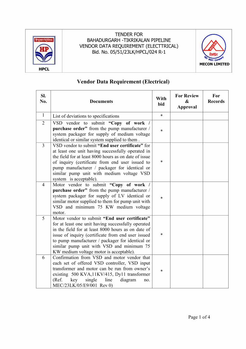
HPCL
TENDER FORBAHADURGARH -TIKRIKALAN PIPELINE
VENDOR DATA REQUIREMENT (ELECTTRICAL)Bid. No. 05/51/23LK/HPCL/024 R-1
MECON LIMITED
Page 1 of 4
Vendor Data Requirement (Electrical)
Sl.No. Documents With
bid
For Review&
Approval
ForRecords
1 List of deviations to specifications *2 VSD vendor to submit “Copy of work /
purchase order” from the pump manufacturer /system packager for supply of medium voltageidentical or similar system supplied to them .
*
3 VSD vendor to submit “End user certificate” forat least one unit having successfully operated inthe field for at least 8000 hours as on date of issueof inquiry (certificate from end user issued topump manufacturer / packager for identical orsimilar pump unit with medium voltage VSDsystem is acceptable).
*
4 Motor vendor to submit “Copy of work /purchase order” from the pump manufacturer /system packager for supply of LV identical orsimilar motor supplied to them for pump unit withVSD and minimum 75 KW medium voltagemotor.
*
5 Motor vendor to submit “End user certificate”for at least one unit having successfully operatedin the field for at least 8000 hours as on date ofissue of inquiry (certificate from end user issuedto pump manufacturer / packager for identical orsimilar pump unit with VSD and minimum 75KW medium voltage motor is acceptable).
*
6 Confirmation from VSD and motor vendor thateach set of offered VSD controller, VSD inputtransformer and motor can be run from owner’sexisting 500 KVA,11KV/415, Dy11 transformer(Ref. key single line diagram no.MEC/23LK/05/E9/001 Rev 0)
*

HPCL
TENDER FORBAHADURGARH -TIKRIKALAN PIPELINE
VENDOR DATA REQUIREMENT (ELECTTRICAL)Bid. No. 05/51/23LK/HPCL/024 R-1
MECON LIMITED
Page 2 of 4
Sl.No. Documents With
bid
For Review&
Approval
ForRecords
7 Confirmations from VSD and motor vendor thatmodel of VSD controller and Low voltage motorsoffered are from the existing regularmanufacturing range.
*
9. Completed VSD datasheet for main pump **
(See note -9)
10 Completed motor data sheet for main pump motor * *11 Completed motor data sheet (for auxiliary motor),
separate for each rating * *
12 Completed experience record format for VSD andmotor, as attached in datasheets *
13 Space requirement for indoor and outdoorequipment * *
14 G.A. drawing and foundation details of VSD andlocal control station for each location *
15 G.A. drawing and foundation details oftransformer and reactor *
16 Motor and terminal box dimensional GAdrawings * *
17 List of cables required for the system along withvoltage grade, type and size * *
18 List of recommended spares for electricalequipment (over and above mandatory spares) *
19 Bill of material *
20 Interface details / schematic block diagrambetween owner's and supplier’s equipment. *
21 Thermal withstand curve and torque-speed curveat 100% and at 80% of rated voltage for mainmotor
*
22 Schematic / Logic diagrams between packageequipment *

HPCL
TENDER FORBAHADURGARH -TIKRIKALAN PIPELINE
VENDOR DATA REQUIREMENT (ELECTTRICAL)Bid. No. 05/51/23LK/HPCL/024 R-1
MECON LIMITED
Page 3 of 4
Sl.No. Documents With
bid
For Review&
Approval
ForRecords
23 Interconnection diagram, term mal block andwiring diagram
*
24 Cable layout on skid showing location of terminal/ junction boxes
*
25 Special installation requirements for cabling,earthing and any other * *
26 Testing procedure and quality assuranceprocedure *
27 Commissioning procedure *28 Facilities available at works for composite motor
drive and motor testing * *
29 Operation and maintenance manual *
30Control supply requirement *
*
31 Test certificates *32 Type test certificates for flameproof equipment
like medium voltage motor, local control panel /control stations, starters etc.,
*
33 Catalogues and brochures for VSD, motor, VSDinput transformer. * *
34 Electric load data (Main drive motor andauxiliaries) and feeder requirements for theseloads
* *
35 GA drawing for Local control station *36 Instruction for storage of electrical equipment at
site *
Notes
1. * Data Required
2. All documents shall be in English Language.
3. Unless otherwise agreed, the number of copies of various drawings anddocuments shall be as below:

HPCL
TENDER FORBAHADURGARH -TIKRIKALAN PIPELINE
VENDOR DATA REQUIREMENT (ELECTTRICAL)Bid. No. 05/51/23LK/HPCL/024 R-1
MECON LIMITED
Page 4 of 4
a. With bids : Same as the number of copies of bidsb. Post order submission : Four copies
for review / recordsc. Final documents : Six prints / one reproducible / one
electronic file4. Post order documents for review / records shall be submitted within four weeks of
release of letter of intent unless otherwise agreed.
5. Documents for review and documents for records shall be submitted in separatefolders and under separate covering letter to facilitate processing by the company.
6. As a part of the contractual obligations, final documents shall be duly boundunder hard cover with clear identification of the equipment tag no, PR no, clientdetails and the name of the project.
7. A blank space measuring 75 mm x 50 mm will be provided on all vendordrawings for marking of review codes, etc.
8. Review of the vendor drawings by MECON would be only to check compatibilitywith basic designs and concepts, and would in no way absolve the manufacturer /fabricator of his responsibility to meet applicable codes, specification andstatutory rules and regulations.
9. Balance data to be submitted which was not submitted at bid stage.