boomvane manual - orc · boomvane - manual - part 1 introduction ... as stipulated in orc’s...
TRANSCRIPT
- PATENTED-
ORC AB, Nya Varvet 97, SE-426 71 V:a Frolunda, Swedenphone +46-31698520, fax +46-31691790, e-mail [email protected]
BoomVane- MANUAL -
part 1 Introductionpart 2 Safety caution and liabilitypart 3 River system configurationpart 4 River boom deployment procedurespart 5 Vessel sweep applicationspart 5.1 Vessel sweep system configurationpart 5.2 Vessel sweep deployment procedurespart 6 Assemblypart 7 Hints on handlingpart 8 Technical specificationspart 9 Maintenancepart 10 Conversion kits & accessoriespart 11 Spare parts list
version 7
© 2004 ORC AB

The wing cascade is kept at an optrimal angle to the water flow by a control ruddermounted between folding arms. The rudder, turned by a separate control line, al-lows for retrieval of the BoomVane to the launching point. Above the rudder, a sta-bilizer wing is mounted, maintaining the vertical inclination of the wing cascade. Afloat is bolted to the top of the wing cascade.
The BoomVane is a flow-powered device for both shore- and vessel based oil boomdeployment.
1 - Introduction
2 - Safety caution and liability
ORC AB does not assume any liability for damage to property or injury topersons or death arising from the use of the BoomVane, any such liability is ex-pressly disclaimed. As stipulated in ORC’s General Conditions of Sale, any legalaction in this context shall be taken under the laws of Sweden.
Working with the BoomVane and related equipment can be dangerous andmay result in injury or death. Proper training, appropriate equipment, ad-equate safety measures and a common sense approach are essential.
A safety area around the deployment site should be established, and onlytrained personnel should work with the BoomVane and related equipment.Extreme caution should be exercised when approaching and handling lines.
Powered by the current flow the BoomVane - held only by a single mooring / towline - swings out and away from the operator with the oil boom in tow. TheBoomVane is completely stable and self-trimming in water speeds ranging from 0.5-5 knots, insensitive to ‘chop’ and fluctuations of the flow. Professional users havesuccessfully deployed the BoomVane in even faster waters.
In rivers and canals this powerful, yet light spill response tool allows for rapid boomdeployment, spill control and recovery without the use of boats, anchors or fixedinstallations. The system can be operated in waters with heavy traffic as the BoomVane(and boom) is easily retrieved to shore and re-launched again without de-mooring.
The BoomVane is also ideal foradvancing systems / vesselsweep operations, allowing forvery wide, single vessel sweeps,with a wide range of systemconfigurations.
The BoomVane is constructed asa cascade of vertical wingsmounted in a rectangular frame.

current
wind
3 - River system configuration
The BoomVane is a versatile spill control tool - perfect for both recovery and deflec-tion modes of operation. As shown in the sketch below, deflection serves two pri-mary purposes: (1) deflection / exclusion booming to protect resources such as waterintakes, beaches or other environmentally sensitive areas; (2) deflecting oil [frommainstream] to a shore-side recovery point.
Cascade mode
currentBoomVane
mooringline
water intake
deflection mode
oil boom
recovery mode
oil boom
BoomVane
oil recovery point
Wind barrier mode
Moored by only one line the BoomVane is completely self-trimming and requires noattendance once deployed. The BoomVane may be used with any type or make of oilboom or skimming system, although shallow draught booms with low drag arerecommended.
For waters where oil is moving downstream with the [typical] mid-channel current,but wind drives oil onto the lee shore, the BoomVane can be used to deploy a verylong shallow draught river boom (>1000 m) with the downstream end of the boomtrailing free in the water.
As the influence on the boom from the current is much greater than that of thewind, the boom will maintain a barrier against the wind-driven oil along a sensitiveshore up to a point where effective recovery is feasible.
Deflection and recovery mode
To gain extended coverage(system width) of the river,multiple BoomVanes can bedeployed in cascadeformation.

4 - River boom deployment procedure1. Determine the system launching point, taking into considerationpracticable upstream (mooring line) and downstream (boom) mooringpoints. Assemble and rig the BoomVane (ref section 6 & 7). Lay out theentire system along the bank - the mooring line taut but some slack on theboom. Set up the mooring points for the up- and downstream ends of thesystem - as close to the water as possible . Trees are ideal, but for ‘barren’banks without large rocks some artifical anchoring system, e.g. a series ofearth nails, may be necessary (light vehicles are NOT recommended asanchors). Connect the BoomVane, mooring line and boom to theconnector plate.
2. Push the BoomVane from the bank and let it float free. Ensure that thestabilizer arms point downstream and the control rudder is swung back tothe ‘out-going’ position when the current ‘caches’ the vanes. The Boom-Vane will swing towards midstream with the boom in tow. Have the controlline manned - not taught, just enough to take up the slack.
3. When the BoomVane has towed out and positioned the boom, themooring line length and/or either of the mooring points may need to beadjusted/moved to achieve optimum boom-to-current angle.
4. The BoomVane control rudder (operated by the control line to shore)stalls the main wing cascade and brings the system back to the shore. Thisoperation is both for system adjustment and recovery, as well as for lettingvessels pass.
Personnel entering the water to launch the BoomVane should wear a safety harness with amanned lifeline to shore. The control rudder line should also be manned on shore whenpersonnel is in the water. When wearing waders extra caution should be taken to avoidfilling these with water. Always be aware of tripping hazards!
Caution!
See part 7 - Hints on handling for futher advice on system launching.
As a safety precution, always take the BoomVane back to shore byoperating the control rudder (see 4. below), thus taking the loadoff the mooring line, before attempting to adjust the mooring linelength. This rule applies to both paying out and taking in line.

1. As in the previous example, determine the system launching point,assemble and rig the BoomVane (ref section 6 & 7). Lay out themooring line only - as taut as possible. Connect the BoomVane, themooring line, and the upstream end of the boom (using a short line)to the connector plate - the bulk of the boom still in its rack/pallet/trailer on shore. Set up the mooring points for the up- and down-stream ends of the system - as close to the water as possible . Con-nect the BoomVane, mooring line and boom to the connector plate.
* Note! Due to local variations in the strength anddirection of the current, and shoreline formation, thedownstream end of the boom may not drift all theway to within easy reach of the shore. As a precau-tion, always have a length of floating line with abouy or fender at the end tied to the end of theboom, which can be caught with e.g. a small grap-nel thrown from shore.
... alternatively ...
2. Push the BoomVane from the bank and let it float free. Ensure thatthe stabilizer arms point downstream and the control rudder is swungback to the ‘out-going’ position - a boat hook may be required to setthe BoomVane in the correct orientation. The BoomVane will swingtowards midstream, with the boom in tow.
3. Once the entire length of boom is out, bring back the BoomVaneto shore by tripping the contol rudder. Giving it a little time, the cur-rent will push in the downstream end of the boom to within reach ofthe shore*.
4. Recover the downstream end of the boom and moor it to shore,selecting a mooring point and/or paying out line so as to provide theslack required for BoomVane to ‘reach’ the desired position in theriver. Re trimming - see (3) in the previous example.
The advantage with this method is that the BoomVane does someof the hard work - unloading and laying out the boom. Also, forany given length of boom, the downstream end of the mooringpoint is more or less given without having to pace the length.Most important though, is that it allows for depoloyment of aboom where the shoreline is not accessible all the way betweenthe launching point and the downstream mooring point.

5 - Vessel sweep applicationsThe stability of the BoomVane in high speeds and choppy seas provides for a rangeof vessel applications in coastal and offshore waters. With long tow lines and shal-low draught coastal booms, sweep widths of 100-150 meters are attainable. Apartfrom the obvious savings when only one towing vessel is required, the operatoralso avoids many of the practical problems inherent in two-vessel sweeps (ref.speed and distance coordination). As an example, with a BoomVane open “U” or“V” sweep, the boom opening is always centered as long as the vessel maintains astraight course. The elasticity of the system also saves boom wear and tear.
Double, trailing open apex U-sweep as fore-sweep to conventional sweep vessel with rigid outrigger arms
BoomVane vessel sweep applicationsexamples
Single, trailing U-sweep offset for 'close shave' of shoreline or shallows
Double off-the-side sweep & recovery system for larger vessels
Double BoomVane'open apex' sweep
5.1 - Vessel sweep system configuration
Off-the-side BoomVane vessel sweep
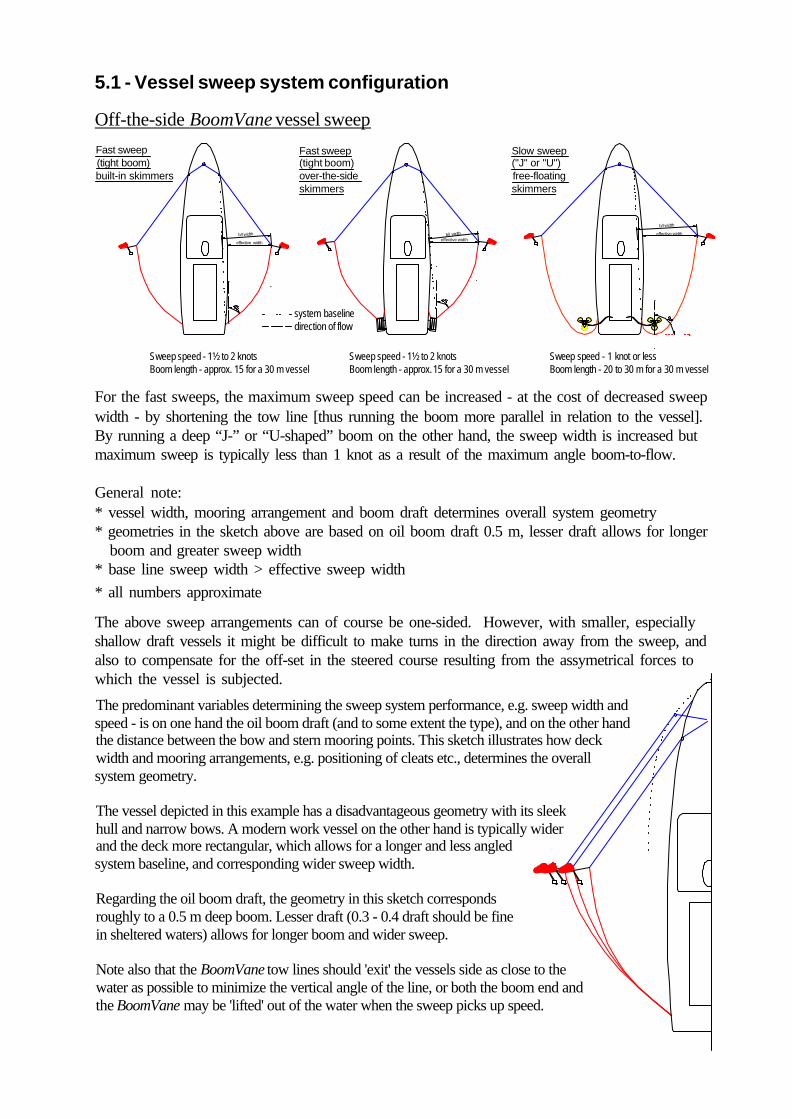
For the fast sweeps, the maximum sweep speed can be increased - at the cost of decreased sweepwidth - by shortening the tow line [thus running the boom more parallel in relation to the vessel].By running a deep “J-” or “U-shaped” boom on the other hand, the sweep width is increased butmaximum sweep is typically less than 1 knot as a result of the maximum angle boom-to-flow.
General note:* vessel width, mooring arrangement and boom draft determines overall system geometry* geometries in the sketch above are based on oil boom draft 0.5 m, lesser draft allows for longer boom and greater sweep width* base line sweep width > effective sweep width* all numbers approximate
The predominant variables determining the sweep system performance, e.g. sweep width and speed - is on one hand the oil boom draft (and to some extent the type), and on the other hand the distance between the bow and stern mooring points. This sketch illustrates how deck width and mooring arrangements, e.g. positioning of cleats etc., determines the overall system geometry.
The vessel depicted in this example has a disadvantageous geometry with its sleek hull and narrow bows. A modern work vessel on the other hand is typically wider and the deck more rectangular, which allows for a longer and less angled system baseline, and corresponding wider sweep width.
Regarding the oil boom draft, the geometry in this sketch corresponds roughly to a 0.5 m deep boom. Lesser draft (0.3 - 0.4 draft should be fine in sheltered waters) allows for longer boom and wider sweep.
Note also that the BoomVane tow lines should 'exit' the vessels side as close to the water as possible to minimize the vertical angle of the line, or both the boom end and the BoomVane may be 'lifted' out of the water when the sweep picks up speed.
Fast sweep (tight boom)built-in skimmers
b/l width
effective width
Fast sweep(tight boom)over-the-side skimmers
b/l widtheffective width
Slow sweep ("J" or "U")free-floating skimmers
b/l width
effective width
Sweep speed - 1½ to 2 knotsBoom length - approx. 15 for a 30 m vessel
Sweep speed - 1½ to 2 knotsBoom length - approx. 15 for a 30 m vessel
Sweep speed - 1 knot or lessBoom length - 20 to 30 m for a 30 m vessel
system baselinedirection of flow
The above sweep arrangements can of course be one-sided. However, with smaller, especiallyshallow draft vessels it might be difficult to make turns in the direction away from the sweep, andalso to compensate for the off-set in the steered course resulting from the assymetrical forces towhich the vessel is subjected.

Vessel trailing BoomVane sweeps
Closed “U”-sweeps as well as open fore-sweeps are deployed well astern of the towing vessel tominimize propeller wash disturbing the oil concentrated in the sweep, and to improve system ge-ometry (longer lines allow for wider sweep swath), which is one of the advantages over off-the-side sweeps. The disadvantage is that the angle direction of flow-to-boom at the bottom of the“U” (applicable for both open and closed systems) allows only for very low sweep speeds or oilis lost under the boom. There are ways to reduce this problem, all of which are based on inducingadditional drag on the bottom of the “U”. Hooking up a skimmer vessel or a skimmer with boomconnectors to the boom opening is one example. Attaching sea anchors to the opening is another:
In the case of an open trailing sweep, a linefrom the open boom opening to the followingskimmer vessel - the latter being ‘dragged’along - the “U” curvature of the boom can bestraightened out to a “V” and thus allow for ahigher sweep speed. If the skimmer vessel islarge and creates execessive drag, it may‘ease’ the load by going dead slow ahead.
There are a number of alternative ways of configuring single vessel, trailing sweeps - single ordouble BoomVanes, open or closed end, with or without attached skimmer or treatment device.
Single vessel, single BoomVane trailingsweep with a NeatSweep dispersantapplicatior hooked up to the end.
Single vessel, double BoomVane trailing sweep, serving as fore-sweep to a Coast Guard skimmer vessel.
“V”-curvature can also be achieved by connect-ing a drouge or sea anchor to the downstreamopening in the boom. The drouge should be runat some depth, to reduce unwanted turbulence atthe surface.
Inducing downstream drag will of course af-fect the BoomVanes and result in a somewhatreduced sweep width - however, this is gener-ally found to be ecceptable in view of the in-creased sweep speed.

5.2 - Vessel sweep deployment procedure
Mark the lines - When operating BoomVanes off both quarters,mark the respective towing lines so that the two units can berun with equal distance from the vessel. This is especially im-portant with open sweeps where the opening must be centredfarthest down-stream of the sweep to be effective.
Reel storage - If the boom is stored on one large reel only, startby reeling on the two towing ends (parallely). This may requirean extra hand or two during launching and recovery but is faster,and as the ‘bottom’ of the U will come on last, it facilitatesswitching boom configuration between open and closed U-sweeps without having to unreel the boom. Use also an evennumber of boom sections so that the opening will be in the mid-dle of the U with equal length of the the two tow lines.
Control line & back-water flap - If operating in ‘unobstructed’ waters where no narrow pas-sages through which the sweep will not pass, run the BoomVanes without the control line – theless lines in the water the better.
Boom opening - When deploying an open-ended sweep andusing an oil boom un-tried in such deployment mode, study[close-up] the behaviour of the boom ends at the opening and beprepared to adjust the lengths of the upper or lower wires /ropes in relation to each other as this relationship controlswhether the boom ends are inclined to dive or ‘plane’ up.
General hints on handling
Extreme caution should be exercised when paying out line while under way. Thecrew member at engine control must be in continuous visual and/or audio contactwith the crew member handling the tow line throughout this sequence.
Back eddies - If the turbulence at the opening leads to oil spreading up-wards along the outside /back of the boom, some operators hook up a few meters of boom to each end at the opening, lettingthese sections trail free after the sweep to hinder such ‘back-eddies’ from forming.
Crane lift - If a crane is used to lift the BoomVane from the deck to the water it may be difficult toreach down to un-hook. Also, if the water is choppy, the BoomVane may bob in the water and thefloat damaged by hitting the hook/ crane arm or smashing into the vessel side. Instead, with theBoomVane still on deck, make fast a handling line to the hook, run it through the BoomVane liftingeye and back through the hook to a handler on deck, who will hold back on the line while theBoomVane is lifted over the railing. With the BoomVane in the water, the line end can be droppedand the line retrieved from the hook.Small boat towing point - A well placed towing point is essential - especially on small boats - tomaintain vessel maneouvrability. If there is no centrally placed towing post or hook, well forwardof the rudder, it is recommended that a bridle with a running block, is rigged between the boatsides.
Off-the-side sweeps
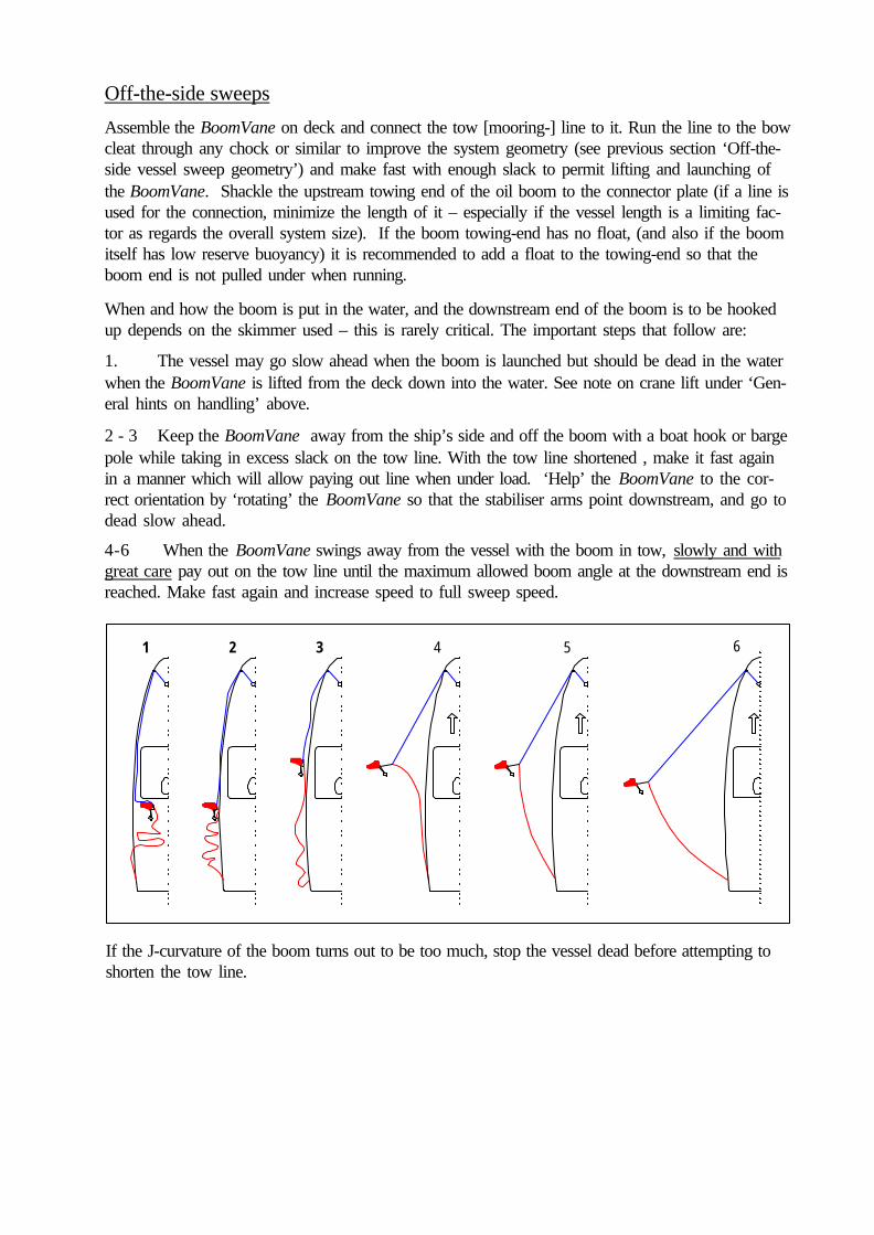
Assemble the BoomVane on deck and connect the tow [mooring-] line to it. Run the line to the bowcleat through any chock or similar to improve the system geometry (see previous section ‘Off-the-side vessel sweep geometry’) and make fast with enough slack to permit lifting and launching ofthe BoomVane. Shackle the upstream towing end of the oil boom to the connector plate (if a line isused for the connection, minimize the length of it – especially if the vessel length is a limiting fac-tor as regards the overall system size). If the boom towing-end has no float, (and also if the boomitself has low reserve buoyancy) it is recommended to add a float to the towing-end so that theboom end is not pulled under when running.
If the J-curvature of the boom turns out to be too much, stop the vessel dead before attempting toshorten the tow line.
When and how the boom is put in the water, and the downstream end of the boom is to be hookedup depends on the skimmer used – this is rarely critical. The important steps that follow are:
1. The vessel may go slow ahead when the boom is launched but should be dead in the waterwhen the BoomVane is lifted from the deck down into the water. See note on crane lift under ‘Gen-eral hints on handling’ above.
2 - 3 Keep the BoomVane away from the ship’s side and off the boom with a boat hook or bargepole while taking in excess slack on the tow line. With the tow line shortened , make it fast againin a manner which will allow paying out line when under load. ‘Help’ the BoomVane to the cor-rect orientation by ‘rotating’ the BoomVane so that the stabiliser arms point downstream, and go todead slow ahead.
2 31 54 6
4-6 When the BoomVane swings away from the vessel with the boom in tow, slowly and withgreat care pay out on the tow line until the maximum allowed boom angle at the downstream end isreached. Make fast again and increase speed to full sweep speed.

Trailing sweeps
With the boom in the water, the procedure for launching the BoomVane(s) is similar to that of theoff-the-side sweep discussed in the previous section. A major difference however, is the positionof the tow line mooring point. In the case of the off-the-side sweep, said position is critical to theoverall system geometry – that of course is not applicable for the trailing sweeps. For all trailingsweeps the tow line mooring point is chosen in view of vessel manoeuvrability [only]. Ideally, thevessel has a towing post or bollard with a ‘clean’ deck aft of it. If it does not a, a bridle should beconsidered. Regardless of how and where the tow lines are made fast, it must be a forward of thevessel rudder or turning may will be difficult if not impossible.
As opposed to the ‘off-the-side’ sweeps, oil recovery is typically done by a vessel other than theone towing the boom sweep. If such a skimmer vessel is a dedicated oil response vessel –whereas the vessel towing the boom can be a true vessel-of-opportunity, and a very small one atthat - it may be convenient to have the skimmer vessel carry the oil booms to the site of operationsand do the actual launching of the booms. The two ends of the boom can then be passed to the towvessel by heaving lines. Regardless of which vessel stores and launches the oil boom, and regard-less off which trailing sweep systems is used – open, closed, single- or two-sided – the commonprocedure is to have the boom launched and in the water with the two towing ends temporarilymade fast to the stern or sides of the tow vessel, before the BoomVanes are launched.
1. Assemble the BoomVane onthe deck (for double BoomVanesweeps, assemble one unit at the timeif work space is limited).
2. With the BoomVane on deckand made fast with a shortened line (alittle slack only to allow lifting it intothe water), take one end of the boom(temporarily made fast to the stern)and pull it up and make it fast to theBoomVane connector plate.
4. If, on the other hand, it is to bea double BoomVane sweep, the pro-cedure with the first BoomVane isrepeated from the other side of thevessel. When lifting the secondBoomVane into the water and hookingup the remaining end of the boom to it,the vessel needs to be more or lessfully stopped.
3. The [first] BoomVane can nowbe now be launched– see previoussection ‘off-the-side sweep’ - and asingle BoomVane sweep set and run-ning. If only a single BoomVane is tobe used the handling line of the end ofthe oil boom still hooked up to thestern, is lengthened and paid out alongwith the BoomVane tow line until thedesired overall geometry is achieved.
1 2 3
4 5
6

1 2 3 4 5
6
Note that in comparison to the off-the-side sweep where it is recommended that the towing end isshackled directly to the connector plate in view of the over-all system geometry, this is not desir-able for the trailing sweeps. To eliminate the risk of the boom end being pulled under when run-ning, a short line (a few metres) can be fitted between the towing end and the connector plate - seelast paragraph under 7 - Hints on handling. This short line also serves as a handling line to facili-tate the aforementioned launching and temporary mooring of the oil boom.
Alternatively, as in the following example, the trailing sweep is launched by one [larger] vessel,but the towing will be performed by a different vessel - either an on-board work boat (as depictedbelow) or any vessel of opportunity.
The only differences as regards system handling, ascompared to the previous example, are:
The oil boom and BoomVanes are launched separatelyfrom the deployment vessel (this is much easier andsafes wear and tear, than lifting the BoomVane with theoil boom hooked up over the rail). The boom towing endline strops and the BoomVane towlines are retained onboard, to be passed across to the tow vessel.
The vessel to tow the sweep takes over the boom towingend line strops and the BoomVane towlines are retainedon board, when drawing up alongside the deploymentvessel. The oil boom towing ends are then shackled tothe BoomVane connector plates from the small boat - aneasy task being closer to the water.

6 - Assembly
Preparation
The two arms on top are the stabilizer arms and the curved plate that joins them atthe end is the control rudder.
Remove the BoomVane from the factory provided shipping/storage crate and placeit on the ground with the two hinged arms facing up.
Initial Assembly
No tools are required for assembly of the BoomVane.
Remove the two locking bolts (withwashers and safety clips) and retainthem for re-insertion after the nextstage of the procedure.
are not wedged) until the hinged ends are contained in the ‘sockets’ and thelocking bolt holes on the main frame and the holes in the stabilizer arms arealigned. Replace the locking bolts removed during the previous step. Securethe locking bolts with the safety clips.
Orientation- color code
Before standing the BoomVane upright, note that it can be oriented in two ways:With the stabilizer arms in position as decribed above, stand the BoomVane up sothat the stabilizer arms and control rudder point downstream (astern), and face theoperator. To facilitate correct orientation, all components of later models are colorcoded red and green respectively - face the current (forward) and think of theBoomVane as a vessel with running lights, also heading upstream - it would showyou green lights if it was on your port side, red light if it was on your starbord side.
Float AttachmentRetain the wing nuts and the two long floatbolts for insertion during the Installation ofLifting Eye procedure below.
Place the red float on top of the main wingframe, with the widest part of the red float,the bulbous nose, being closest to the hingedsection (this may require turning the floatover) - if the BoomVane is color coded,match the colored stickers. Ensure that thepositioning plugs on the float are fully in-serted in the maching holes on the mainwing frame.
Gently swing the stabilizer arms up-wards (ensuring the bridle shackles

Attachment of Stabiliser Wing
The rectangular stabilizer wing hasthree short metal extension protrudingfrom the base. The centered extensionhas a slot for the short square-neckbolt that fits the hole on the stabilizerarm (near the control rudder). The ex-tensions protruding from the cornersof the stabilizer wing fits the slot at thevery end of the stabilizer arm.Remove the bolt, washer and wing nut from the stabilizer arm. Place the flat base ofthe stabiliser wing on the top of the of the stabilizer arm above the point where thecontrol rudder is attached. Note that the wing can be inserted two ways - the stabi-lizer wing must be oriented so that the wing is parallel to the main vane assembly(see color coding). Insert the metal extension fully into the metal slot at the end ofthe stabilizer arm. Secure with the bolt, washer and wing nut and hand tighten.
Re-orientation / re-configuration when changing sides...
Control Rudder Return SpringsThe control rudder return springs ensure thatthe control rudder (after having been ‘acti-vated’) always swing back to ’drive’ positionwhen the control line is released. The need forthese springs is commented on under part 7-Hints on handling.
To re-configure the BoomVane for use on the other side of the river or vessel,simply remove the lifting eye, float and stabilizer wing, turn themain wing frame upside down and reinstall the removed pieceson the ‘new up-side’.
Installation of Lifting Eye
Place the lifting eye on top of the red float. Aligne the bolt holes of the BoomVaneassembly, the red float and the lifting eye. Insert the bolts from below. Note thesquare neck of the bolts that slots into corresponding holes in the main wing frame.Reinstall each wing nut and hand tighten very firmly.
As of 2004, control rudder return springs arestandard on all BoomVanes, but earlier mod-els can easily be fitted with them as well.
If the spring holder plate ‘comes off’ whenremoving or inserting the stabilizer wing bolt,follow the instructions under 9- Maintenance.

A very important feature of therigging arrangement - contribut-ing to the exceptional stability ofthe BoomVane system - is theconnector plate arrangement.The boom is not suspended fromthe vane but connected directly tothe mooring line. The BoomVaneitself is hooked up to the connectorplate by a single bridle only,thereby allowed to ‘fly free’ like akite.
Rigging
1. The bridle that connects the BoomVane to the connector plate.2. The 4 mm control rudder line.3. The mooring line that anchors the entire system to a point upstream.4. The boom strop that connects the oil boom to the connector plate.5. The downstream boom line that anchors the end of the boom to shore.
A typical river system comprises 5 lines:
Lines 1-3 are always supplied with the BoomVane. Lines 4-5 pertain tothe oil boom and are not supplied with the BoomVane.
Bridle & Bridle Block
Check that the main bridle is securely connected by the two shackles to theBoomVane main wing frame. Ensure there are no knots in the bridle line and that itruns freely through the main bridle block. Any jamming may cause the BoomVaneto ‘porpoise’ when deployed.
Control Line Block and Control Line
The control line block is suspended on a short cable below the main bridle block.Ensure the control line block is running freely.
To hook up the control line, run it through the small control line block (fastened bya wire strop to the main bridle block), and tie it (bowline knot) to the shackle onthe center rib of the control rudder.
Back-water Flap - see part 7 - Hints on Handling
Note! Always use the appropriate line for the control rudder. A line with too much drag mayresult in the rudder swinging over without any action from the operator.

Connector PlateThe triangular connector plate of stainless has shackle holes at each point – twoholes diam. 13 mm, one hole diam. 10,5 mm. If the connector plate is stood on itsshortest side the top hole is for the shackle of the mooring line to the upstreamanchor point. The BoomVane bridle is attached to the 10,5 mm shackle point andthe third hole (13 mm) is for the oil boom shackle.
The BoomVane mooring line must be low-friction and of small diameter to mini-mize drag - thereby allowing for a longer boom to be deployed. Low-stretch isimportant to minimize sagging. The line should have neutral bouyancy to minimisethe risk of snagging on underwater/bottom objects, during launching. A line with abreak load of min. 6500 kgf is required for the standard BoomVane, 4500 kgf forthe shallow water model. The Dyneema lines delivered with the BoomVane complywith all the above requirements and are fitted with a stainless steel thimble on theend for the connector plate shackle, as well as with a float to compensate for theconnector plate weight in the water. Use of other lines is not recommended.
Mooring/ Tow Line
... essential knots:
The bow-line will always open when relieved. Recommended for allapplications where no trimming is required.
Do not underestimate the load on the system lines, in particular the mooring/ tow line.As a safety precution, during shore-based operations, always take the BoomVane back toshore by operating the control rudder, thus taking most of the load off the line, beforeattempting to adjust the line length. This rule also applies when paying out line.
The line used to secure the oil boom to the connector plate should not be too short(<5m), or the head of the oil boom will be dragged under water - especially if theboom towing end has no float. If the line sinks, it can be fitted with a float near themiddle to ensure that it cannot snag under the BoomVane during launching. The lineshould also have a diameter of no less than 25 mm (1”) - see 7 - Hints on handling.
Connecting the oil boom
Two turns or more + a double hitch allows line to be paid out under load -recommended for onshore-side mooring points.

7 - Hints on handling
• ‘Heading’ relative to the oil boom mooring point can be gained by mooring the BoomVane further ‘out’ [towards mistream] - if such alternative mooring point is found - thus running the mooring line more parallel to the current.
• Increase the distance between the two shore moorings by moving either the up- stream or downstream point. Thereafter, lengthen the mooring line if/as required to achieve an effective boom geometry - see further appendix 1.1 (Deployment geometry). The last alternative is to shorten the oil boom.
What to do if the oil boom sags (too baggy, too much “J-curvature”)?
• If the current is stronger further out, insert a length of line between thebridle block and the connector plate to allow the BoomVane to reach the strongercurrent and thus gaining additional force to straighten out the oil boom.
What to do when there is no current near the shore to ‘start the BoomVane off’?
Should the current near the shore be insufficient for ‘launching’ the system (<½knot) - but stronger further out - a line can be inserted between the connector plateand the bridle block (like in the previous example) to allow the BoomVane to reachthe stronger flow without being ‘held back’ by the boom.
NOTE! To insert a line between the connector plate and the vane bridle block - as in the abovenoted special cases - a hex driver is required for opening the shackles. (Such shackles are used inthe BoomVane system wherever the shackles are NOT opened in typical operation or storagehandling).
BoomVane
mooring point alternativesto straighten out the boom oil boom
How to avoid the BoomVane coming in too fast towards shore when beingretrieved, making it difficult to stop and send back out again?
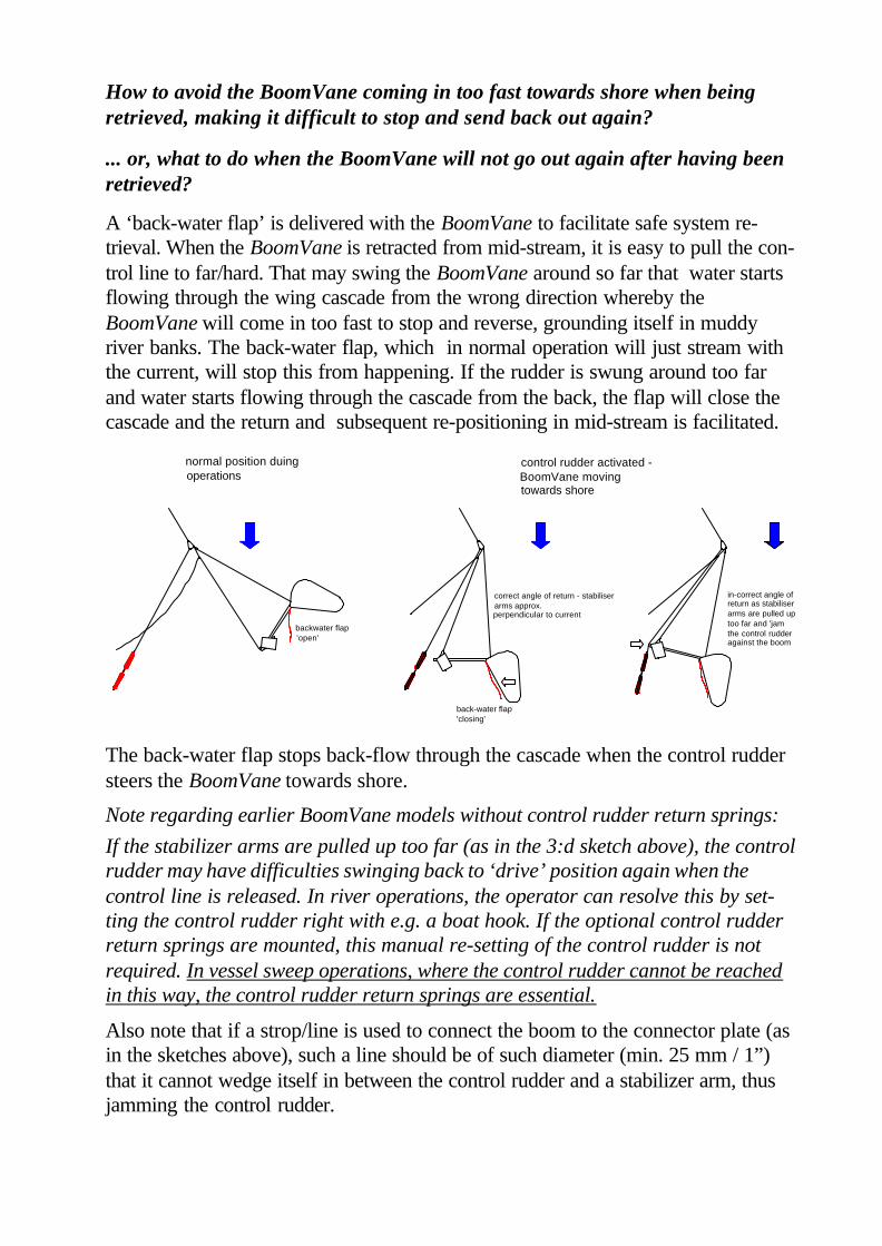
A ‘back-water flap’ is delivered with the BoomVane to facilitate safe system re-trieval. When the BoomVane is retracted from mid-stream, it is easy to pull the con-trol line to far/hard. That may swing the BoomVane around so far that water startsflowing through the wing cascade from the wrong direction whereby theBoomVane will come in too fast to stop and reverse, grounding itself in muddyriver banks. The back-water flap, which in normal operation will just stream withthe current, will stop this from happening. If the rudder is swung around too farand water starts flowing through the cascade from the back, the flap will close thecascade and the return and subsequent re-positioning in mid-stream is facilitated.
The back-water flap stops back-flow through the cascade when the control ruddersteers the BoomVane towards shore.
Also note that if a strop/line is used to connect the boom to the connector plate (asin the sketches above), such a line should be of such diameter (min. 25 mm / 1”)that it cannot wedge itself in between the control rudder and a stabilizer arm, thusjamming the control rudder.
If the stabilizer arms are pulled up too far (as in the 3:d sketch above), the controlrudder may have difficulties swinging back to ‘drive’ position again when thecontrol line is released. In river operations, the operator can resolve this by set-ting the control rudder right with e.g. a boat hook. If the optional control rudderreturn springs are mounted, this manual re-setting of the control rudder is notrequired. In vessel sweep operations, where the control rudder cannot be reachedin this way, the control rudder return springs are essential.
... or, what to do when the BoomVane will not go out again after having beenretrieved?
backwater flap'open'
back-water flap'closing'
normal position duing operations
control rudder activated - BoomVane moving towards shore
correct angle of return - stabiliser arms approx.perpendicular to current
in-correct angle ofreturn as stabiliserarms are pulled uptoo far and 'jam the control rudderagainst the boom
Note regarding earlier BoomVane models without control rudder return springs:

8 - Technical specifications
Materials:
Wing unit:1785 x 310 x 1012 mm = 0.56 m3, 46 kg (standard model)1785 x 310 x 505 mm= 0.28 m3, 34 kg (shallow water model)
Float unit: 1400 x 205 x 800 mm = 0.23 m3, 16 kg
Performance:
1.1 m (standard model)0.55 m (shallow water model)
Water speed range: 0,5-5 knots
Mooring/tow line:standard model: Dyneema 12 mm x 150 m
breakload >7000 kgfshallow water model: Dyneema 10 mm x 100 m
breakload >5000 kgf
Boom length*:Standard model: 100-150 metre (300-500 feet) shallow draught boomShallow water model: 50-100 metre (150-300 feet) river boom
Blocks: Ronstan or Rutgerson
Bridle line: Dyneema 10 mm,
Connector plate, pins, bolts& shackles: all stainless steel
Float: GRP, foam-filled (EPS & PU)
Stabilizer arms: aluminum 6063-T6 [Int. AA]
Control line: 4 mm x 150 m trim line
Overall dimensions & weight:
Draught:
* (typical - varying with type/size of boom and site conditions)
Vanes, rudder & stabilizer wing: aluminum 6082-T6 [Int. AA]
Control rudder return springs: plastic coated GRP rods, aluminimum holders
Frame: aluminium 5083-T6 [Int. AA]

9 - Maintenance
Replacing control rudder shaft bolts,bearings and slide washers - tightenonly until the play of the washer iseliminated. Do not over-tighten thebolts – the rudder should turn easily.
• Store in dry atmosphere, out of direct sunlight.
• For repair of damages to the float, epoxy filler and laminate is recommended. Thoroughly clean and dry the damaged area before application.
• Use only original spare parts from ORC, whenever possible.
• Check and replace all bent or worn shackles, bolts and other fittings.
• Check all lines for chafing etc – replace on any sign of wear and tear.
• Check rudder bearings and washers for wear and tear – replace in good time.
• Always rinse in fresh water after use in the sea.
• Use only mild detergents and solvents on the float, rinse thoroughly with freshwater. Hot water/high pressure cleaning of float should be avoided.
Replacing the stabilizer arm slidewashers - tighten the lock nut until allplay is eliminated, then some more..the arms should slide rather stiffly.
If the stabilizer arms are to be dismantled, note - before dismantling! - that thetwo arms differ in that the hole geometry is mirrored (control rudder shaft holenot being centered).
Also refer to these sketchesfor BoomVane conversion kits
The back-water flap is dismantled byremoving the key-ring at either end ofthe steel rod, then sliding out the rod.
• Check the control rudder return springs - apply a drop of grease on the rudderblade, where the spring rod ball rests.

Turn the rudder to active/drive position(resting fully on the stoppers).
Fitting/ replacing control rudder return springs
Then, slide the spring holder plate alongthe stabilizer arm so that the bolt hole inthe holder plate is aligned with the stabi-lizer wing bolt hole. Insert the coach boltand tighten the wing nut firmly by hand.
With the spring rod on the inside of the rud-der blade, twist by hand the spring holderplate so that the stabilizer arm fits betweenthe two end stops (Allen screw heads) of thespring holder plate.
The springs are delivered in pairs (mirrored) and are mounted on both stabilizerarms using the stabilizer wing bolt and nut (the washer is excluded).
The procedure below applies to both mounting new/ replacement springs and re-mounting of the spring holder plate when it has ‘come off’ when removing or in-serting the stabilizer wing bolt.

10 - Conversion kits & accessories
For oil boom deployment in very shallow rivers and waterways (depth < 1 metre) there is ashallow water model of the BoomVane.
To reduce overall system costs, the shallow water model utilises, as far as possible, the same systemcomponents as the full size (standard) model. Only the main wing assembly, the control rudder andthe back-water flap differ - these are halved in height, giving the shallow water model a draught ofapprox. 550 mm.
The shallow water model can be ordered either as a complete unit, or as a conversion kit to thestandard BoomVane. With a shallow water conversion kit and the stabilizer arms and wing of thestandard BoomVane, a shallow water model can be assembled following the steps noted for thestandard model.
However, we recommend a different mooring line diameter for the shallow water version - the lighterload requires only a 10 mm Dyneema line. (By reducing the line diameter, total drag is also reduced -enhancing BoomVane performance.)
.. flash (sensor controlled)
...radar reflector
Shallow water model
Vessel sweep applications
To ensure safe navigation in the vicinity of a site of operations,the following optional accessories can be mounted on theBoomVane float:
Safe navigation
In principle, any fast water skimmer can be usedwith the BoomVane system. However, the RiverCircus by ORC is developed for this particularapplication. The River Circus is an artificiallagoon-type skimmer that allows recovery of oil,with a minimum of water. It is easily carried bytwo men, hooks up and is launched in minutes.Contact ORC for detailed info.
Oil recovery
For vessel sweep applications, theBoomVane must be equipped with controlrudder return springs that are mounted oneach of the stabilizer arms. As of 2004, allBoomvanes are delivered with conreolrudder return springs, but the springs can alsobe fitted on earlier models - contact ORC forrecommendations.

11 - Spare parts list - BoomVanepart no
article mtrl./make BV-STD* BV-SW**
Wing frame (complete conversion kit incl rudder) aluminium 1000-00 1100-00 “ wing frame only aluminium 1000-01 1100-01
Float (complete kit) foam-filled GRP 1001-00 “ bolt, washer, wing nut (x2) stainless steel 1001-01
Stabilizer arm pair (complete kit) aluminium, foam filled 1002-00 “ hinge bolt incl. washer, lock nut (x2) stainless steel 1002-01 “ lock bolt incl. washer, hairpin (x2) stainless steel 1002-02 “ hairpins (x5) stainless steel 1002-03 “ slide washers (x4) polythylene 1002-04
Stabilizer wing (complete kit) aluminium 1003-00 “ bolt incl. washer & wing nut (x1) stainless steel 1003-01
Control rudder (complete kit) aluminium 1004-00 1104-00 “ shaft bolt, washers, bearings, lock nut (x2) complete assembly kit 1004-01 “ bearing (x2) acetate 1004-02 “ slide washer (x2) polyethylene 1004-03 “ end stop bushings (x4) acetate 1004-04Control rudder return springs (set of 2) alu., plastic coated GRP 1004-05
Lift-eye bracket aluminium 1005-00Connector plate stainless steel 1006-00
Back-water flap (complete kit incl.rod) 1007-00 1107-00 “ rod, spacers, key-rings stainless steel 1007-01 1107-01 “ flap reinforced PVC fabric 1007-02 1107-02
Bridle (complete kit) 1008-00 “ bridle block (incl shackle & control line block) Ronstan/Rutgerson 1008-01 “ control line block, wire strop, eyebolt Ronstan/Rutgerson 1008-02 “ 7 m x 10 mm bridle line with thimble ends Dyneema, stainless steel 1008-03 “ bridle shackle (x2) 8 mm stainless steel 1008-04
Control line (with A4 shackle, on reel) 4 mm Trim line x150 m 1009-00
Mooring lines, Dyneema SK75 (one end with ss eye) 12 mm x150m 1010-0110 mm x100 m 1110-02
Wing nuts x5 (fits float bolts and stabiliser wing bolt) stainless steel 1011-01Shackle x2 (mooring line-, boom line-) stainless steel 1012-01Holders (for flash lites and radar reflectors) alu + 40 mm clamps (flash) 1013-01
alu + 54 mm clamps (radar) 1013-02Flash lite (day-light sensor) specify white or orange flash 1014-00Radar reflector tube type, 500 x 54 mm 1015-00
* BoomVane standard model ** BoomVane shallow water model