bnd ts catia manikin kinematic optimization -...
TRANSCRIPT
Prepared by: Bill Harbin –Technical Director 20-May-09
BND TechSourceBND TechSourceBND TechSourceBND TechSourceBND TechSourceBND TechSourceBND TechSourceBND TechSource
Ergonomic Manikin Manipulation Ergonomic Manikin Manipulation Ergonomic Manikin Manipulation Ergonomic Manikin Manipulation Ergonomic Manikin Manipulation Ergonomic Manikin Manipulation Ergonomic Manikin Manipulation Ergonomic Manikin Manipulation usingusingusingusingusingusingusingusing
CATIA V5 DMU KinematicsCATIA V5 DMU KinematicsCATIA V5 DMU KinematicsCATIA V5 DMU KinematicsCATIA V5 DMU KinematicsCATIA V5 DMU KinematicsCATIA V5 DMU KinematicsCATIA V5 DMU Kinematics(Steps 5 (Steps 5 (Steps 5 (Steps 5 (Steps 5 (Steps 5 (Steps 5 (Steps 5 -------- 11 the optimized solution)11 the optimized solution)11 the optimized solution)11 the optimized solution)11 the optimized solution)11 the optimized solution)11 the optimized solution)11 the optimized solution)
BND TechSourceBND TechSourceBND TechSourceBND TechSourceBND TechSourceBND TechSourceBND TechSourceBND TechSource
Prepared by: Bill Harbin –Technical Director 20-May-09
� In the previous example, we showed a simple solution to manipulate an Ergonomic Manikin using CATIA DMU Kinematics.
� In that example the angle of the feet do not follow the angle of the pedals.
� In this example we will optimize the pedals to maintain contact with the feet.
BND TechSourceBND TechSourceBND TechSourceBND TechSourceBND TechSourceBND TechSourceBND TechSourceBND TechSource
Prepared by: Bill Harbin –Technical Director 20-May-09
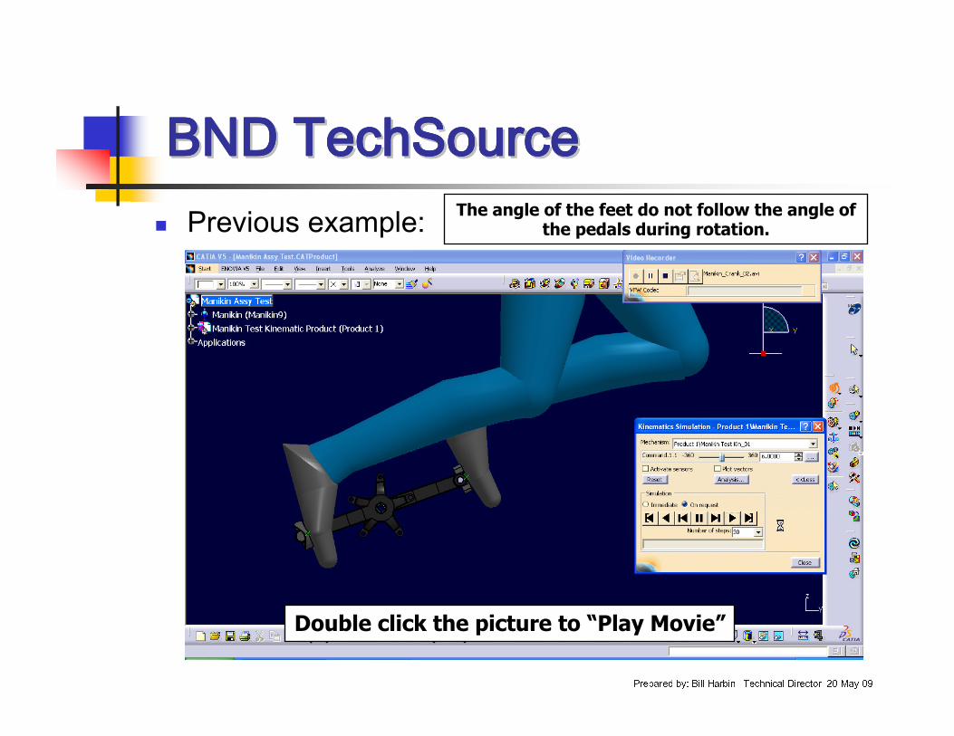
� Previous example:
Double click the picture to “Play Movie”
The angle of the feet do not follow the angle of the pedals during rotation.
BND TechSourceBND TechSourceBND TechSourceBND TechSourceBND TechSourceBND TechSourceBND TechSourceBND TechSource
Prepared by: Bill Harbin –Technical Director 20-May-09
� The rotation angle of the pedals is set to a 1:1 ratio of the crank rotation within the kinematic set.
� While the Manikin may be “attached” to the pedals, it is driven by the kinematic set and therefore not editable inside the Kinematic function.
� The main problem to solve in this example is to get the pedals to follow the feet.
BND TechSourceBND TechSourceBND TechSourceBND TechSourceBND TechSourceBND TechSourceBND TechSourceBND TechSource
Prepared by: Bill Harbin –Technical Director 20-May-09
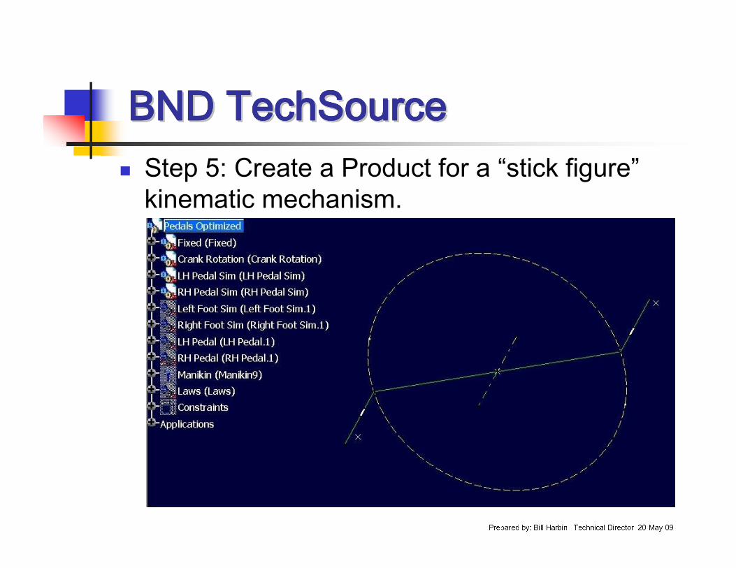
� Step 5: Create a Product for a “stick figure”kinematic mechanism.
BND TechSourceBND TechSourceBND TechSourceBND TechSourceBND TechSourceBND TechSourceBND TechSourceBND TechSource
Prepared by: Bill Harbin –Technical Director 20-May-09
� There will be four Parts to build the kinematic mechanism:
� Fixed� Crank Rotation� LH Pedal Simulator� RH Pedal Simulator
BND TechSourceBND TechSourceBND TechSourceBND TechSourceBND TechSourceBND TechSourceBND TechSourceBND TechSource
Prepared by: Bill Harbin –Technical Director 20-May-09
� Other Parts within the Product will be:
� Manikin (Ergonomic Design & Analysis)� Left Foot Simulator� Right Foot Simulator� LH Pedal (3D Part)� RH Pedal (3D Part)� Laws
BND TechSourceBND TechSourceBND TechSourceBND TechSourceBND TechSourceBND TechSourceBND TechSourceBND TechSource
Prepared by: Bill Harbin –Technical Director 20-May-09
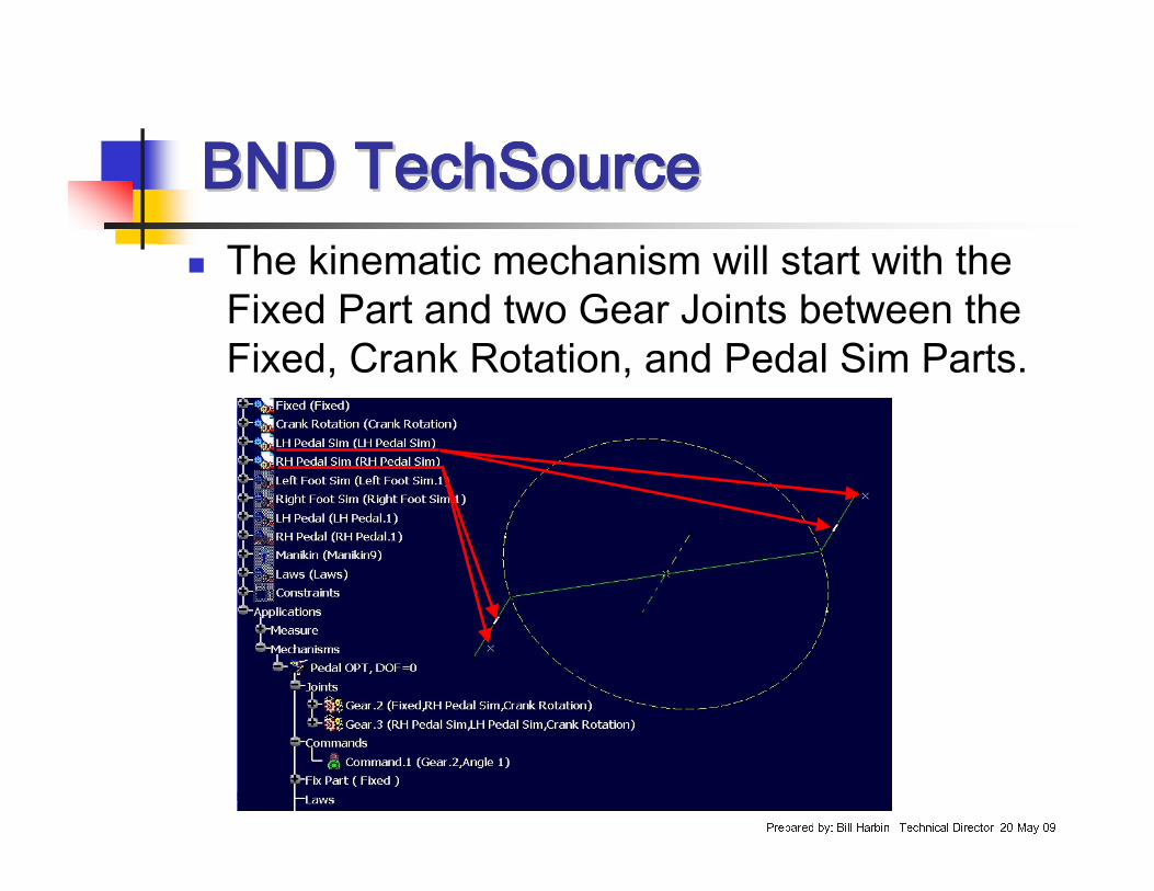
� The kinematic mechanism will start with the Fixed Part and two Gear Joints between the Fixed, Crank Rotation, and Pedal Sim Parts.
BND TechSourceBND TechSourceBND TechSourceBND TechSourceBND TechSourceBND TechSourceBND TechSourceBND TechSource
Prepared by: Bill Harbin –Technical Director 20-May-09
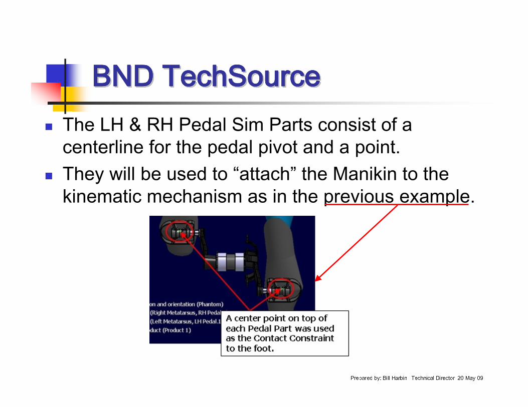
� The LH & RH Pedal Sim Parts consist of a centerline for the pedal pivot and a point.
� They will be used to “attach” the Manikin to the kinematic mechanism as in the previous example.
BND TechSourceBND TechSourceBND TechSourceBND TechSourceBND TechSourceBND TechSourceBND TechSourceBND TechSource
Prepared by: Bill Harbin –Technical Director 20-May-09
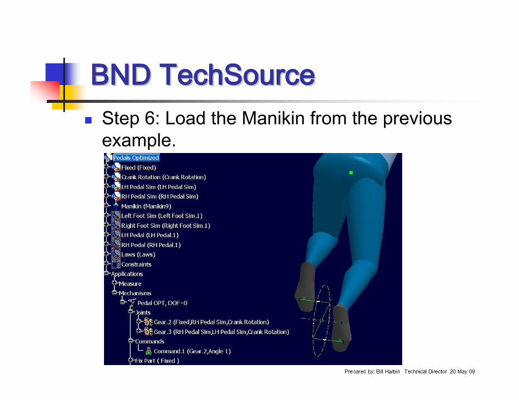
� Step 6: Load the Manikin from the previous example.
BND TechSourceBND TechSourceBND TechSourceBND TechSourceBND TechSourceBND TechSourceBND TechSourceBND TechSource
Prepared by: Bill Harbin –Technical Director 20-May-09
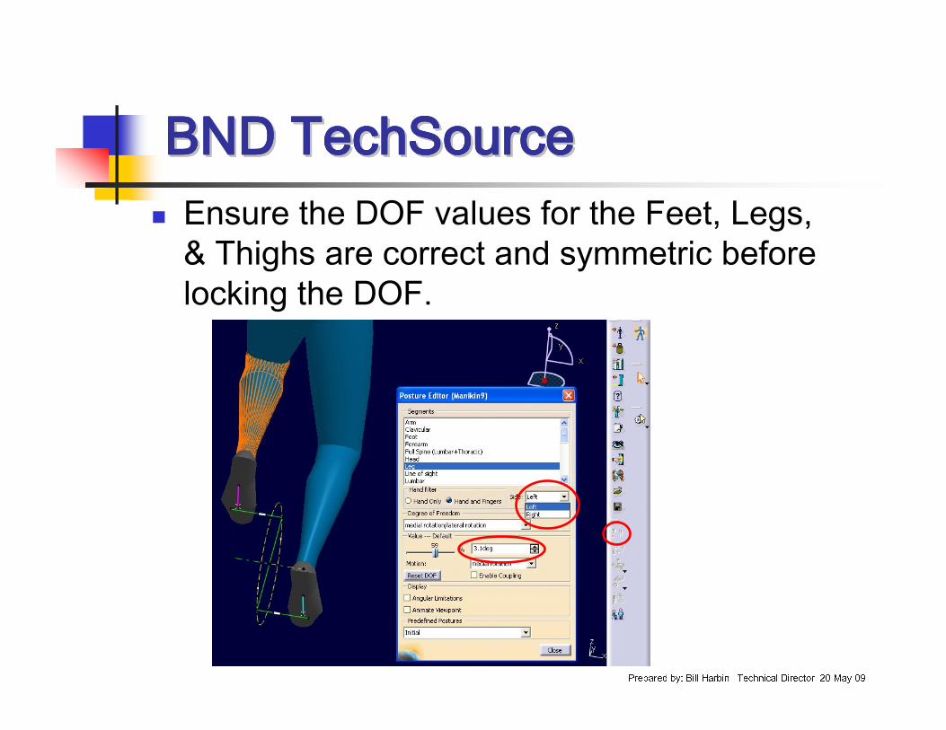
� Ensure the DOF values for the Feet, Legs, & Thighs are correct and symmetric before locking the DOF.
BND TechSourceBND TechSourceBND TechSourceBND TechSourceBND TechSourceBND TechSourceBND TechSourceBND TechSource
Prepared by: Bill Harbin –Technical Director 20-May-09
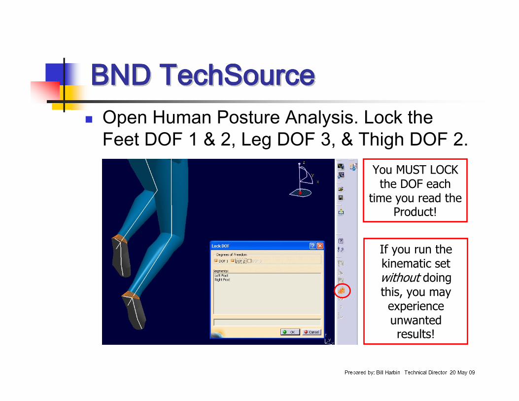
� Open Human Posture Analysis. Lock the Feet DOF 1 & 2, Leg DOF 3, & Thigh DOF 2.
If you run the kinematic set without doing this, you may experience unwanted results!
You MUST LOCK the DOF each
time you read the Product!
BND TechSourceBND TechSourceBND TechSourceBND TechSourceBND TechSourceBND TechSourceBND TechSourceBND TechSource
Prepared by: Bill Harbin –Technical Director 20-May-09
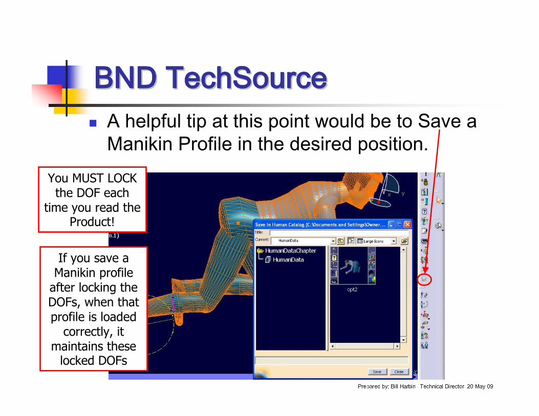
� A helpful tip at this point would be to Save a Manikin Profile in the desired position.
You MUST LOCK the DOF each
time you read the Product!
If you save a Manikin profile after locking the DOFs, when that profile is loaded correctly, it
maintains these locked DOFs
BND TechSourceBND TechSourceBND TechSourceBND TechSourceBND TechSourceBND TechSourceBND TechSourceBND TechSource
Prepared by: Bill Harbin –Technical Director 20-May-09
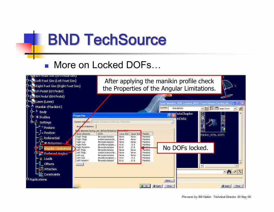
� More on Locked DOFs…After applying the manikin profile check the Properties of the Angular Limitations.
No DOFs locked.
BND TechSourceBND TechSourceBND TechSourceBND TechSourceBND TechSourceBND TechSourceBND TechSourceBND TechSource
Prepared by: Bill Harbin –Technical Director 20-May-09
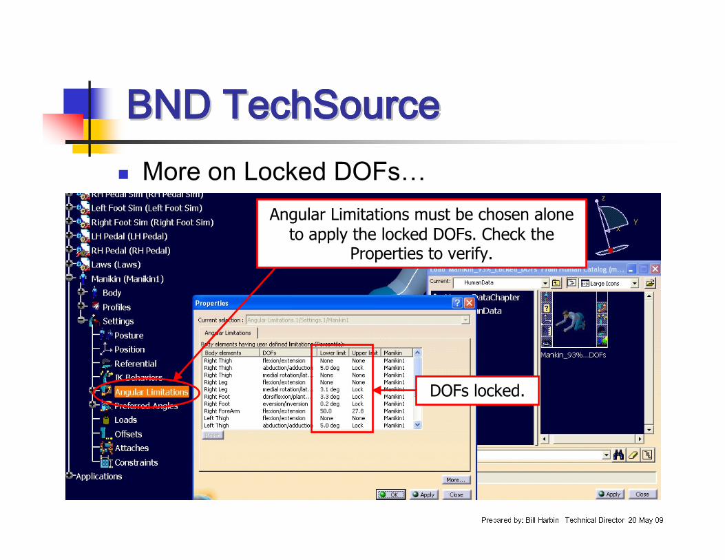
� More on Locked DOFs…
DOFs locked.
Angular Limitations must be chosen alone to apply the locked DOFs. Check the
Properties to verify.
BND TechSourceBND TechSourceBND TechSourceBND TechSourceBND TechSourceBND TechSourceBND TechSourceBND TechSource
Prepared by: Bill Harbin –Technical Director 20-May-09
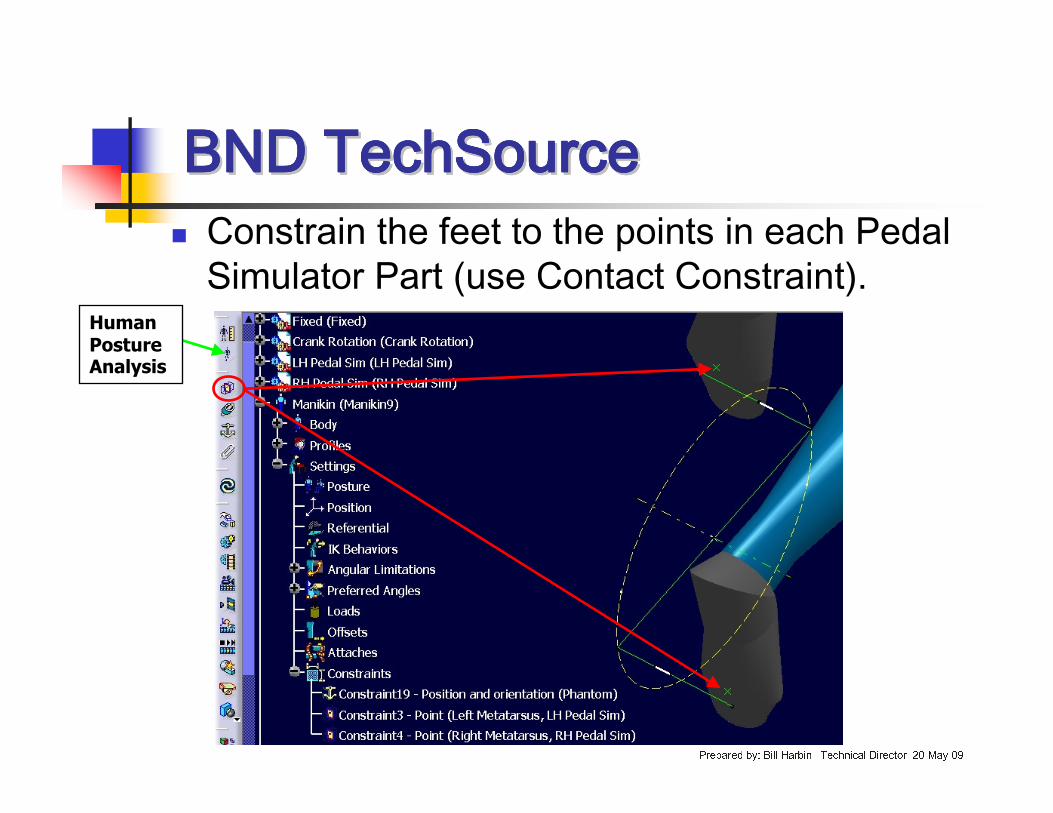
� Constrain the feet to the points in each Pedal Simulator Part (use Contact Constraint).
Human Posture Analysis
BND TechSourceBND TechSourceBND TechSourceBND TechSourceBND TechSourceBND TechSourceBND TechSourceBND TechSource
Prepared by: Bill Harbin –Technical Director 20-May-09
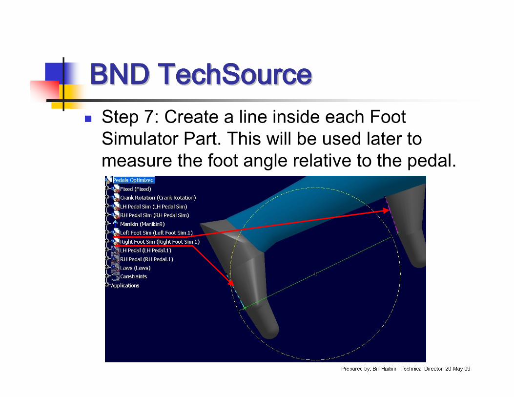
� Step 7: Create a line inside each Foot Simulator Part. This will be used later to measure the foot angle relative to the pedal.
BND TechSourceBND TechSourceBND TechSourceBND TechSourceBND TechSourceBND TechSourceBND TechSourceBND TechSource
Prepared by: Bill Harbin –Technical Director 20-May-09
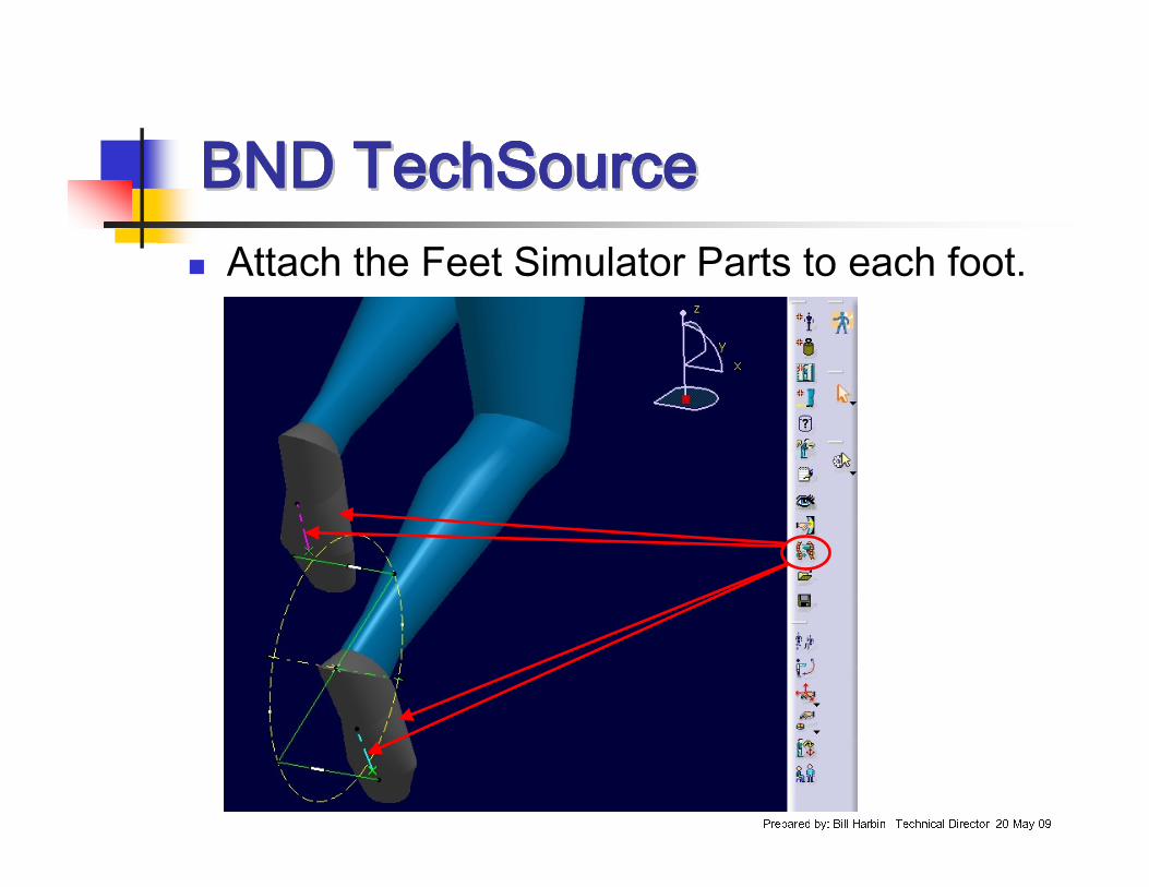
� Attach the Feet Simulator Parts to each foot.
BND TechSourceBND TechSourceBND TechSourceBND TechSourceBND TechSourceBND TechSourceBND TechSourceBND TechSource
Prepared by: Bill Harbin –Technical Director 20-May-09
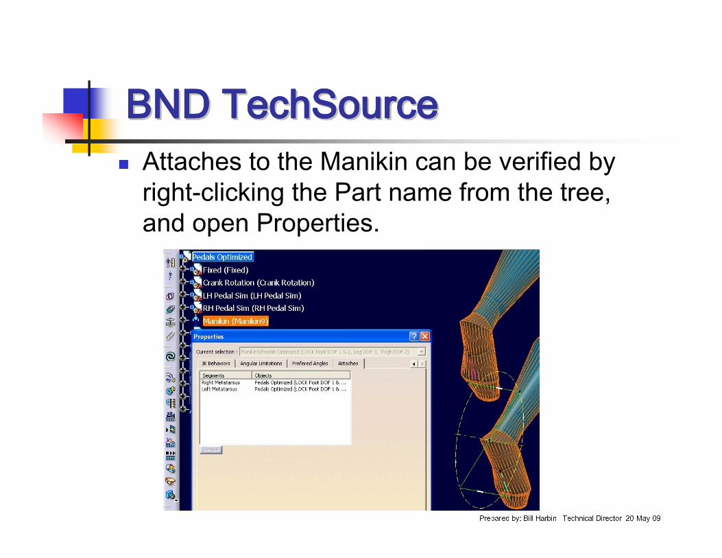
� Attaches to the Manikin can be verified by right-clicking the Part name from the tree, and open Properties.

BND TechSourceBND TechSourceBND TechSourceBND TechSourceBND TechSourceBND TechSourceBND TechSourceBND TechSource
Prepared by: Bill Harbin –Technical Director 20-May-09
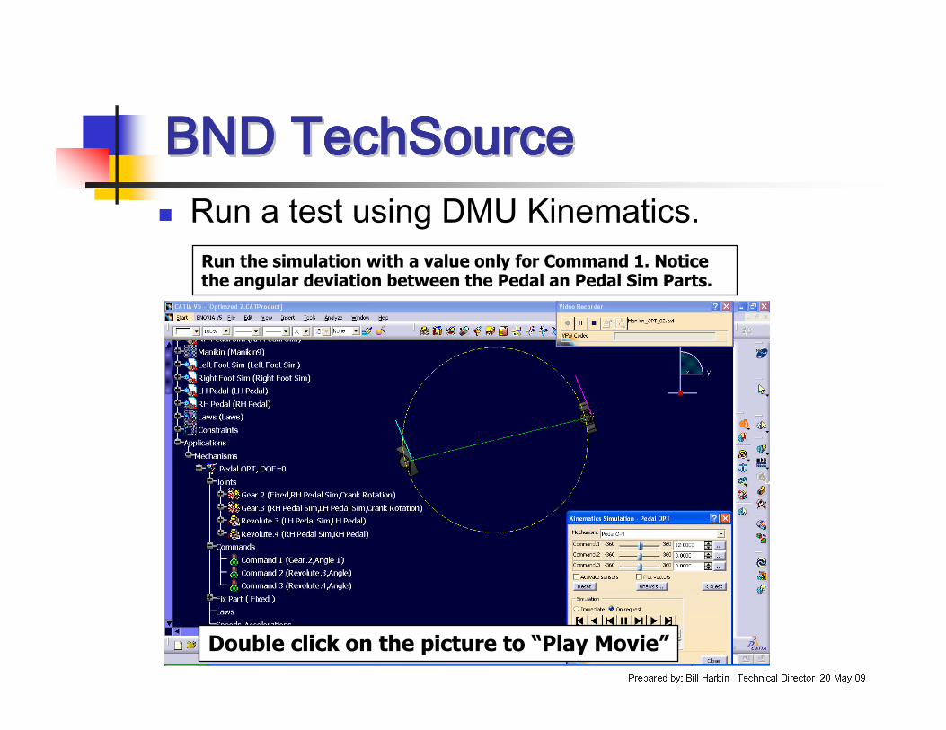
� Run a test using DMU Kinematics.
Double click on the picture to “Play Movie”
BND TechSourceBND TechSourceBND TechSourceBND TechSourceBND TechSourceBND TechSourceBND TechSourceBND TechSource
Prepared by: Bill Harbin –Technical Director 20-May-09
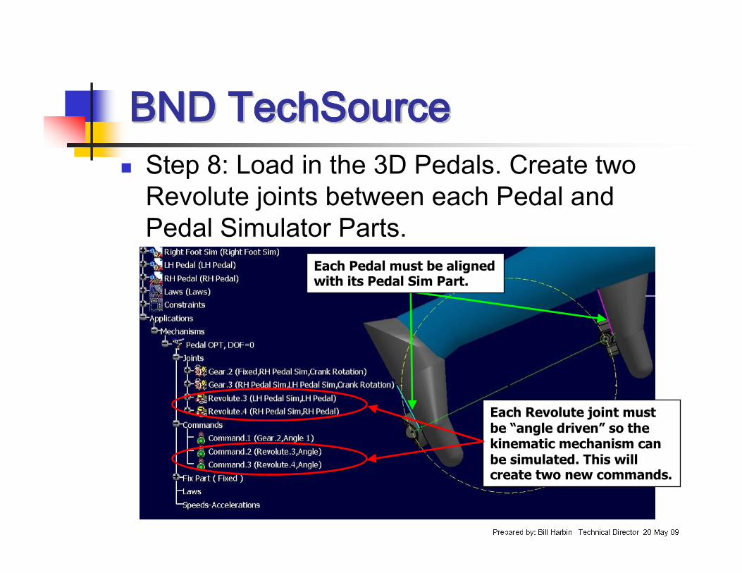
� Step 8: Load in the 3D Pedals. Create two Revolute joints between each Pedal and Pedal Simulator Parts.
Each Revolute joint must be “angle driven” so the kinematic mechanism can be simulated. This will create two new commands.
Each Pedal must be aligned with its Pedal Sim Part.
BND TechSourceBND TechSourceBND TechSourceBND TechSourceBND TechSourceBND TechSourceBND TechSourceBND TechSource
Prepared by: Bill Harbin –Technical Director 20-May-09
� Run a test using DMU Kinematics.
Double click on the picture to “Play Movie”
Run the simulation with a value only for Command 1. Notice the angular deviation between the Pedal an Pedal Sim Parts.
BND TechSourceBND TechSourceBND TechSourceBND TechSourceBND TechSourceBND TechSourceBND TechSourceBND TechSource
Prepared by: Bill Harbin –Technical Director 20-May-09
� The Pedal Sim Parts are “attached” to the Manikin.
� The Manikin is constrained to the kinematic mechanism.
� This means the angular deviation due to the kinematic simulation occurs outside the kinematic mechanism.
� To correct this, we must measure the angular deviation and apply the measurement back into the kinematic mechanism.
BND TechSourceBND TechSourceBND TechSourceBND TechSourceBND TechSourceBND TechSourceBND TechSourceBND TechSource
Prepared by: Bill Harbin –Technical Director 20-May-09
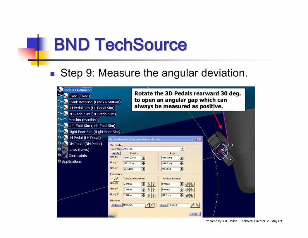
� Step 9: Measure the angular deviation.Rotate the 3D Pedals rearward 30 deg. to open an angular gap which can always be measured as positive.
BND TechSourceBND TechSourceBND TechSourceBND TechSourceBND TechSourceBND TechSourceBND TechSourceBND TechSource
Prepared by: Bill Harbin –Technical Director 20-May-09
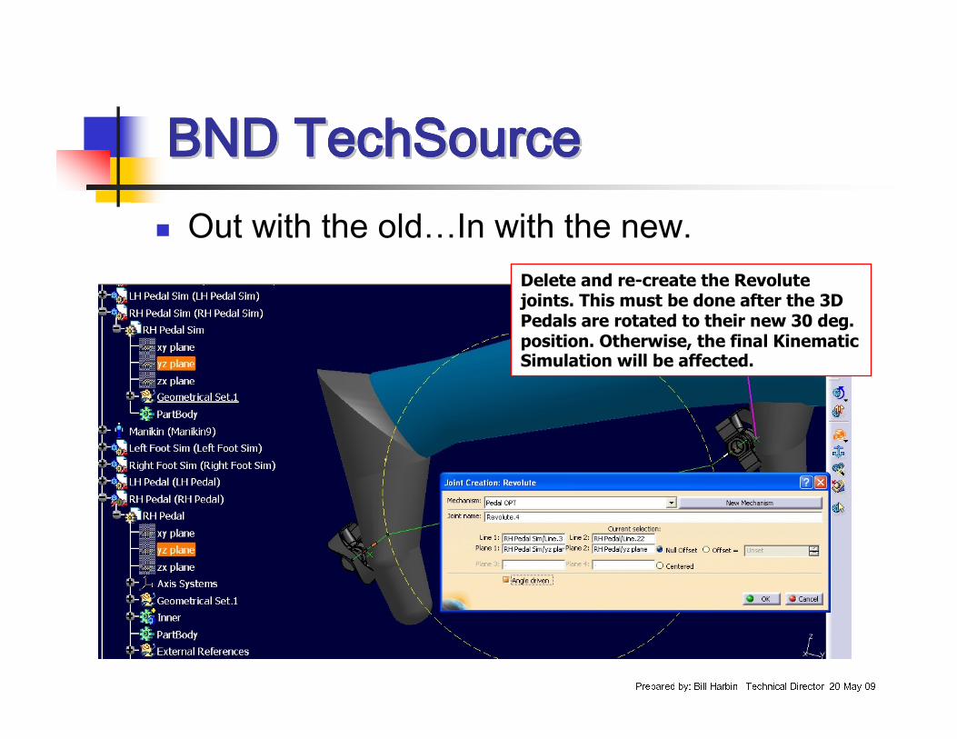
� Out with the old…In with the new.Delete and re-create the Revolute joints. This must be done after the 3D Pedals are rotated to their new 30 deg. position. Otherwise, the final Kinematic Simulation will be affected.
BND TechSourceBND TechSourceBND TechSourceBND TechSourceBND TechSourceBND TechSourceBND TechSourceBND TechSource
Prepared by: Bill Harbin –Technical Director 20-May-09
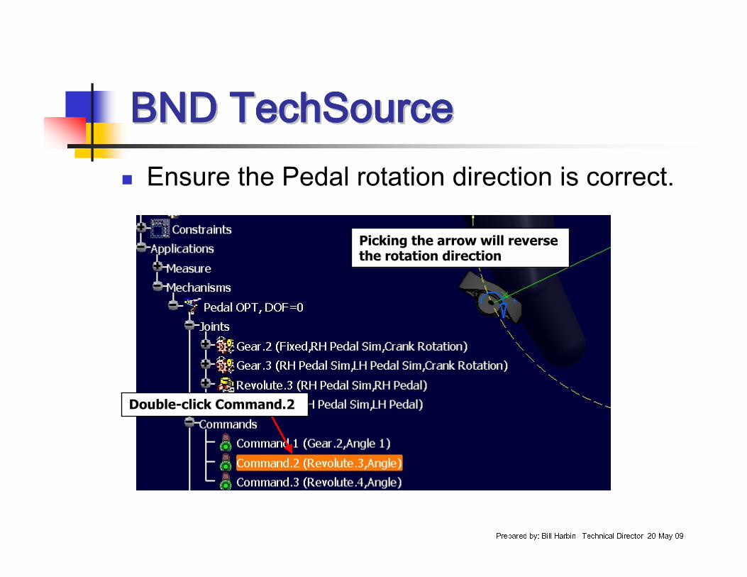
� Ensure the Pedal rotation direction is correct.
Double-click Command.2
Picking the arrow will reverse the rotation direction
BND TechSourceBND TechSourceBND TechSourceBND TechSourceBND TechSourceBND TechSourceBND TechSourceBND TechSource
Prepared by: Bill Harbin –Technical Director 20-May-09
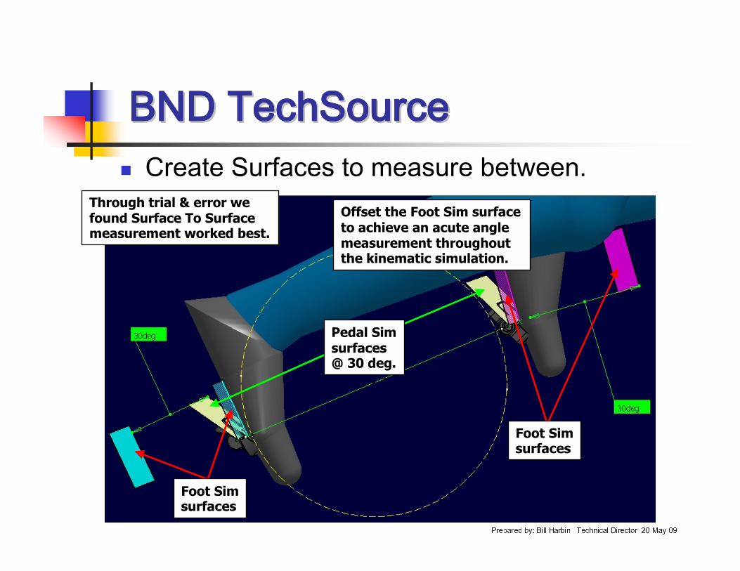
� Create Surfaces to measure between.Through trial & error we found Surface To Surface measurement worked best.
Offset the Foot Sim surface to achieve an acute angle measurement throughout the kinematic simulation.
Pedal Sim surfaces @ 30 deg.
Foot Sim surfaces
Foot Sim surfaces
BND TechSourceBND TechSourceBND TechSourceBND TechSourceBND TechSourceBND TechSourceBND TechSourceBND TechSource
Prepared by: Bill Harbin –Technical Director 20-May-09
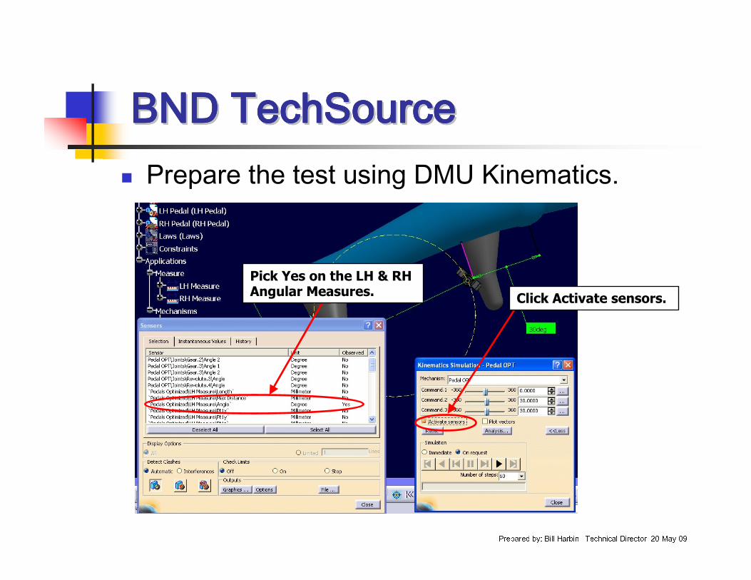
� Prepare the test using DMU Kinematics.
Click Activate sensors.
Pick Yes on the LH & RH Angular Measures.
BND TechSourceBND TechSourceBND TechSourceBND TechSourceBND TechSourceBND TechSourceBND TechSourceBND TechSource
Prepared by: Bill Harbin –Technical Director 20-May-09
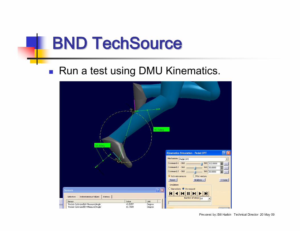
� Run a test using DMU Kinematics.
BND TechSourceBND TechSourceBND TechSourceBND TechSourceBND TechSourceBND TechSourceBND TechSourceBND TechSource
Prepared by: Bill Harbin –Technical Director 20-May-09
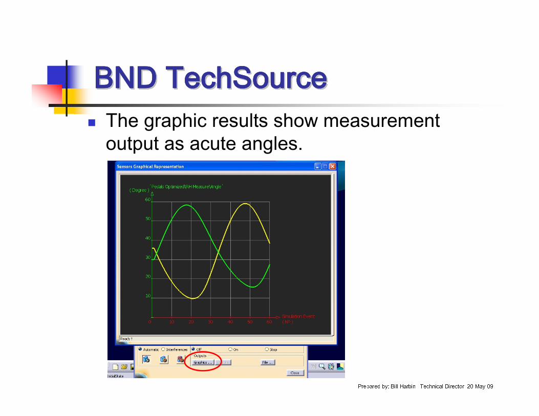
� The graphic results show measurement output as acute angles.
BND TechSourceBND TechSourceBND TechSourceBND TechSourceBND TechSourceBND TechSourceBND TechSourceBND TechSource
Prepared by: Bill Harbin –Technical Director 20-May-09
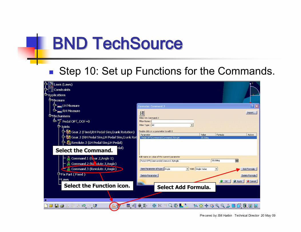
� Step 10: Set up Functions for the Commands.
Select the Function icon. Select Add Formula.
Select the Command.
BND TechSourceBND TechSourceBND TechSourceBND TechSourceBND TechSourceBND TechSourceBND TechSourceBND TechSource
Prepared by: Bill Harbin –Technical Director 20-May-09
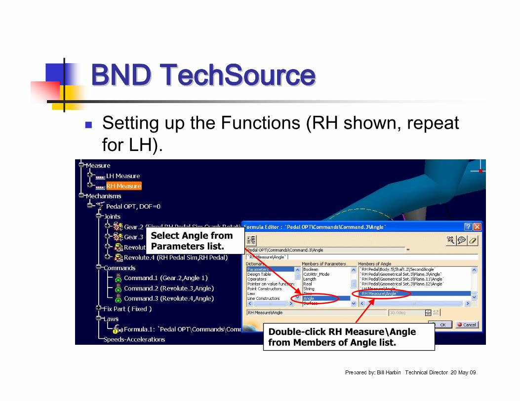
� Setting up the Functions (RH shown, repeat for LH).
Select Angle from Parameters list.
Double-click RH Measure\Angle from Members of Angle list.
BND TechSourceBND TechSourceBND TechSourceBND TechSourceBND TechSourceBND TechSourceBND TechSourceBND TechSource
Prepared by: Bill Harbin –Technical Director 20-May-09
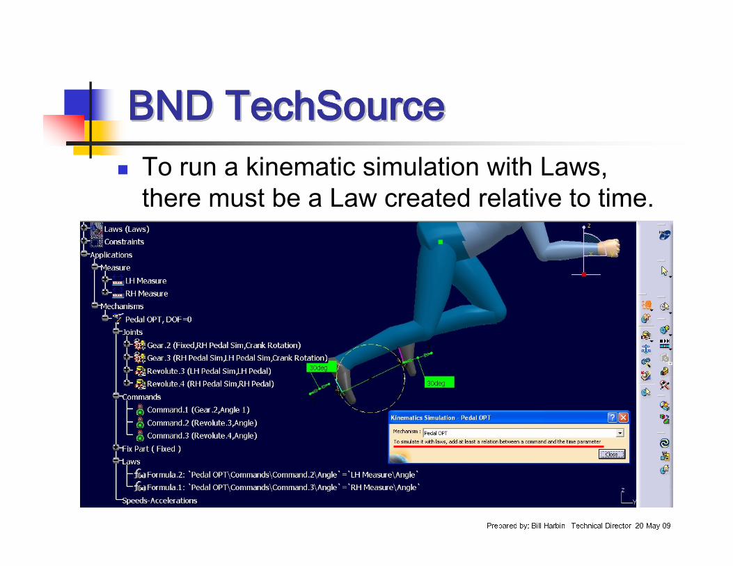
� To run a kinematic simulation with Laws, there must be a Law created relative to time.
BND TechSourceBND TechSourceBND TechSourceBND TechSourceBND TechSourceBND TechSourceBND TechSourceBND TechSource
Prepared by: Bill Harbin –Technical Director 20-May-09
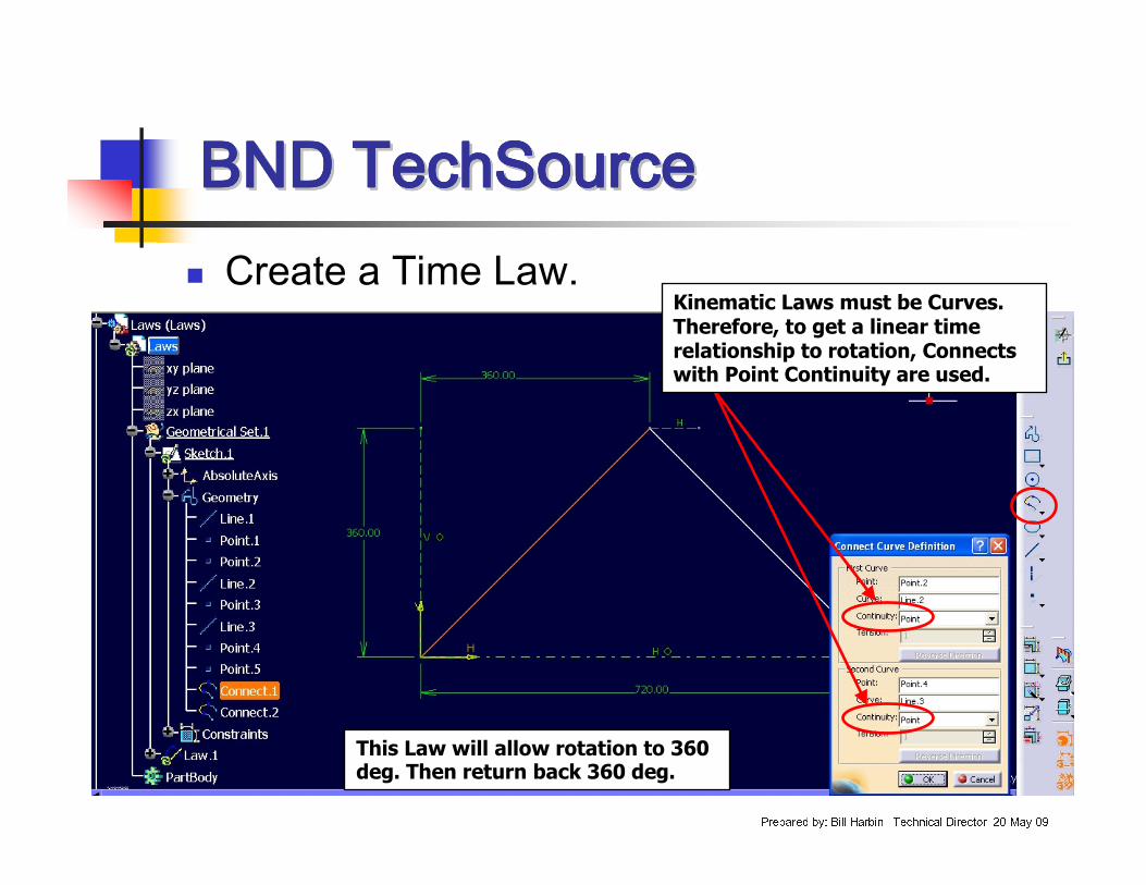
� Create a Time Law.Kinematic Laws must be Curves. Therefore, to get a linear time relationship to rotation, Connects with Point Continuity are used.
This Law will allow rotation to 360 deg. Then return back 360 deg.
BND TechSourceBND TechSourceBND TechSourceBND TechSourceBND TechSourceBND TechSourceBND TechSourceBND TechSource
Prepared by: Bill Harbin –Technical Director 20-May-09
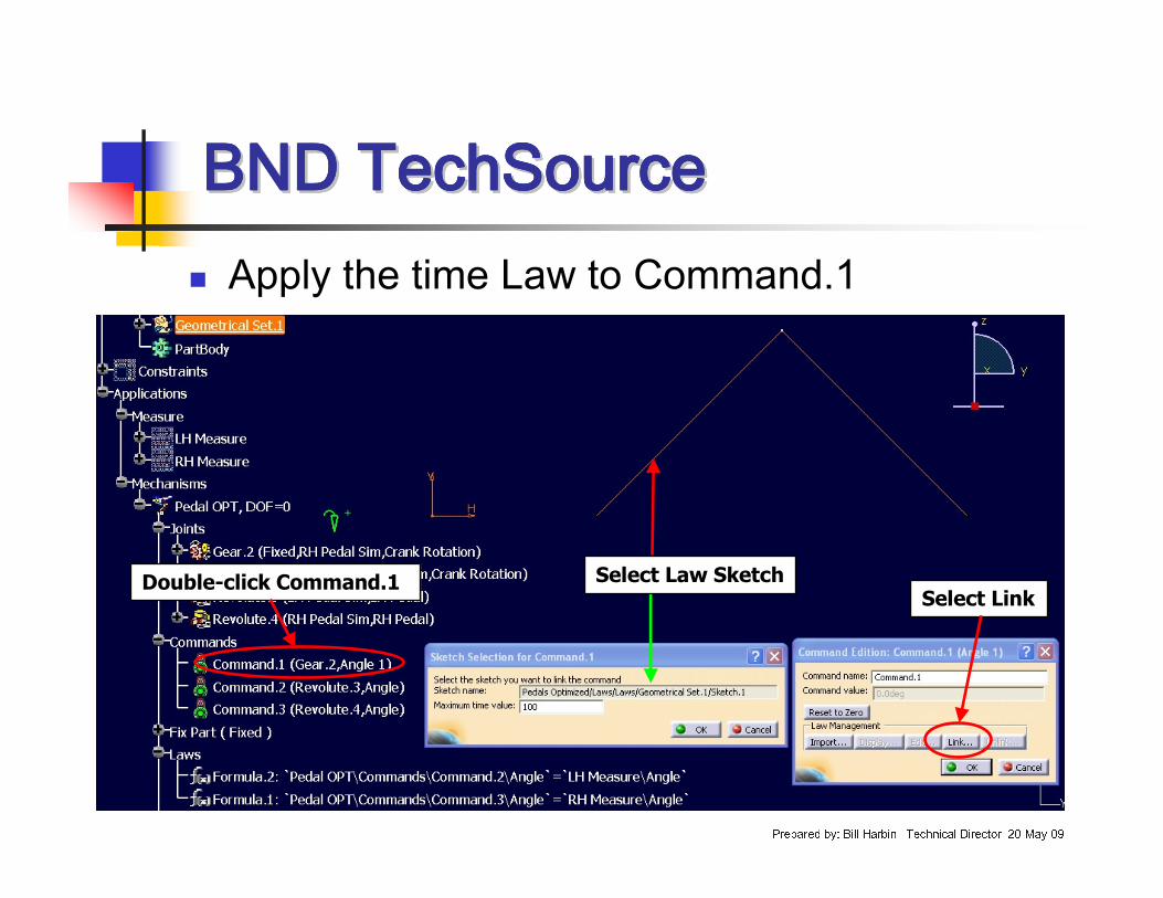
� Apply the time Law to Command.1
Double-click Command.1Select Link
Select Law Sketch
BND TechSourceBND TechSourceBND TechSourceBND TechSourceBND TechSourceBND TechSourceBND TechSourceBND TechSource
Prepared by: Bill Harbin –Technical Director 20-May-09
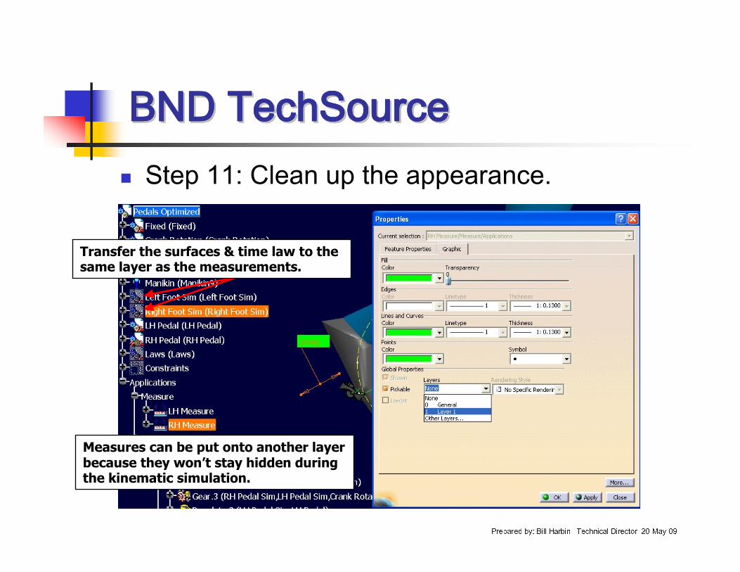
� Step 11: Clean up the appearance.
Transfer the surfaces & time law to the same layer as the measurements.
Measures can be put onto another layer because they won’t stay hidden during the kinematic simulation.
BND TechSourceBND TechSourceBND TechSourceBND TechSourceBND TechSourceBND TechSourceBND TechSourceBND TechSource
Prepared by: Bill Harbin –Technical Director 20-May-09
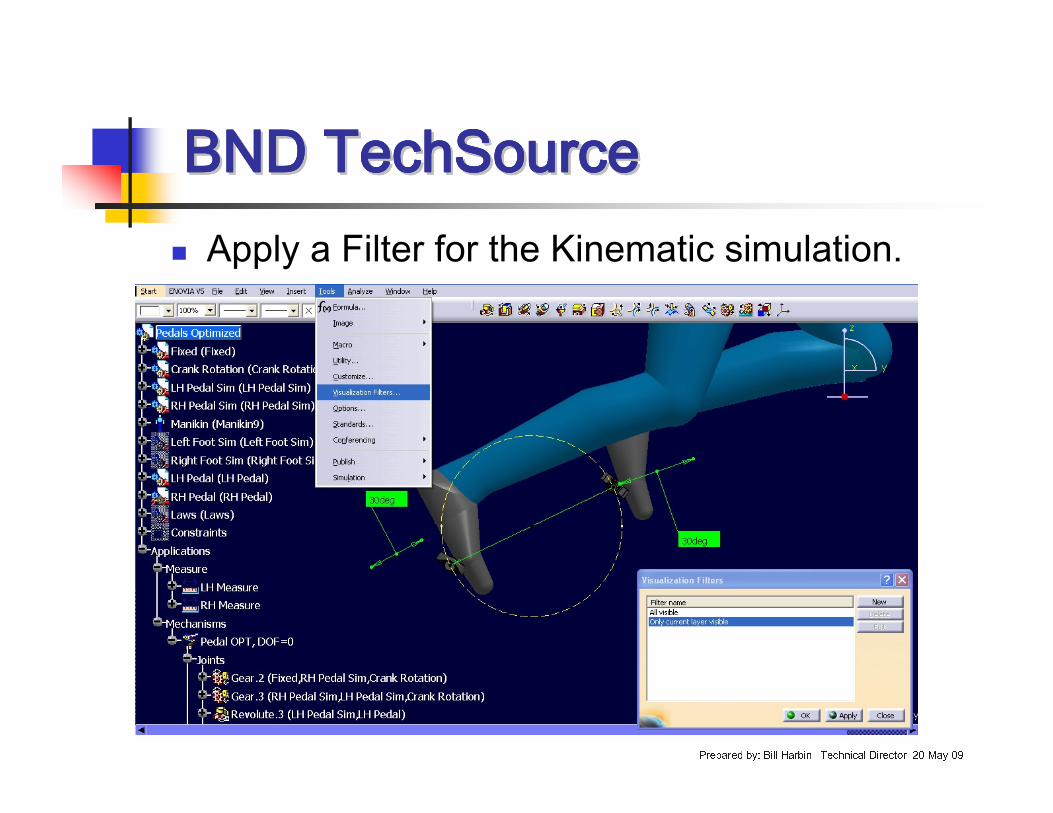
� Apply a Filter for the Kinematic simulation.
BND TechSourceBND TechSourceBND TechSourceBND TechSourceBND TechSourceBND TechSourceBND TechSourceBND TechSource
Prepared by: Bill Harbin –Technical Director 20-May-09
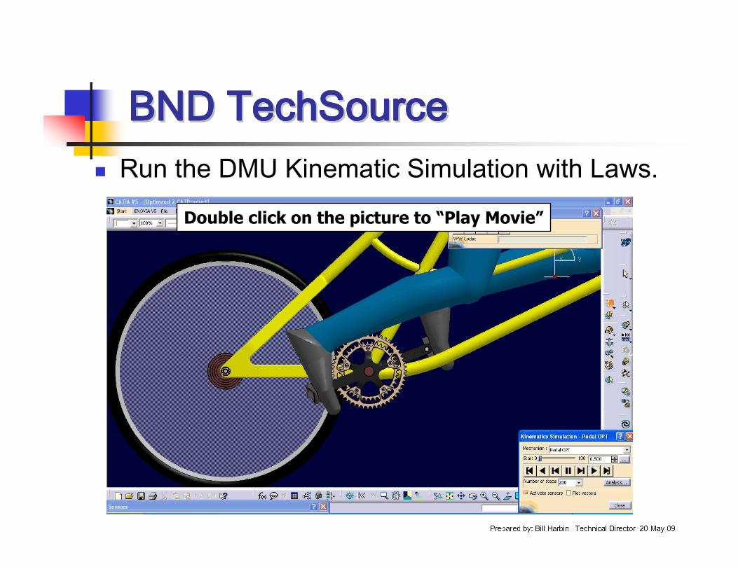
� Run the DMU Kinematic Simulation with Laws.Double click on the picture to “Play Movie”
BND TechSourceBND TechSourceBND TechSourceBND TechSourceBND TechSourceBND TechSourceBND TechSourceBND TechSource
Prepared by: Bill Harbin –Technical Director 20-May-09
� Conclusion: This is an example of how to use CATIA DMU Kinematics along with Ergonomic Design & Analysis to simulate a 3D Manikin pedaling a bicycle.
We hope this will help those who need this type of simulation.
As always, we are open to any discussions this may bring.