bldc motor drive controller for electric vehicles · bldc motor drive controller for electric...
TRANSCRIPT

BLDC Motor Drive Controller
for Electric Vehicles
Alireza Tashakori Abkenar
Faculty of Science, Engineering and Technology
Swinburne University of Technology
A thesis submitted for the degree of
Doctor of Philosophy
May 2014

I would like to dedicate this thesis to my loving parents.

Abstract
Electric vehicles are the best solution for green transportation due to their
high efficiency and zero greenhouse gas emissions. Various electric motors have
been used as the propulsion system of electric vehicles. Performance of brushed
Direct Current (DC) motors, induction motors, switched reluctance motors, and
permanent magnet Brushless DC (BLDC) motors are compared according to
the in-wheel motor technology requirements under normal and critical conditions
through simulation. This study shows that BLDC motors are the most suitable
electric motor for the high performance electric vehicles. An accurate model
of a BLDC motor is needed to investigate the motor performance for different
control algorithms. Therefore a BLDC motor with an ideal back-Electro Motive
Force (EMF) voltage and its control drive are modelled in Simulink. Correct
performance of the BLDC motor drive model is validated through experimental
data.
Direct torque control technique is a type of flux linkage based sensorless con-
trol methods in the BLDC motors. In this thesis, direct torque control switching
technique of the BLDC motor is discussed. Results of this study show effec-
tive torque control, reduction of torque ripples and improved performance of the
BLDC motor compared to the conventional switching control techniques.
An optimized back-EMF zero crossing detection based sensorless technique of
the BLDC motor is presented in this thesis. The proposed sensorless algorithm
generates commutation signals of the BLDC motor according to back-EMF zero
crossing detection points of only one phase of the motor. This algorithm is
simple and remarkably reduces sensing circuitry, noise susceptibility and cost of
the sensorless BLDC motor drives. A digital pulse width modulation (PWM)
switching technique is implemented to control the speed of the BLDC motor.
Stability of the proposed sensorless BLDC motor drive using a digital PWM
speed controller is analysed by Lyapunov’s second method. A novel condition
for duty cycle of the PWM speed controller is introduced for stability analysis
of the BLDC motor drive. Effectiveness of the proposed sensorless algorithm
and correctness of the introduced PWM controller stability condition are verified
ii

Abstract
through simulation and experimental results.
Robust performance of the in-wheel BLDC motor drives is an important fac-
tor in safety of the electric vehicles. Effect of inverter switch faults of an in-wheel
BLDC motor on performance of the four wheel drive electric vehicle is studied
through simulation. Results show unstable performance of the electric vehicle af-
ter fault occurrence and demonstrate need of the fault tolerant control system for
the in-wheel motors. This thesis presents two novel fault tolerant control systems
for inverter switch faults and position detection sensor faults in the BLDC motor
drives. Performance of the BLDC motor is studied under various fault conditions
through a validated simulation model. Knowledge based tables were developed
to diagnose the inverter switch and Hall Effect sensor faults based on discrete
Fourier transform analysis of the BLDC motor line voltages. The developed fault
diagnosis algorithms are simple and capable of detecting the fault occurrence,
identify fault type and the faulty switch or position sensor of the BLDC mo-
tor drive. Simulation results and the proposed knowledge based fault diagnosis
tables are validated through experimental data. The proposed fault diagnosis
algorithms do not need massive computational effort and can be implemented as
a subroutine of the main control algorithm of the BLDC motor.
iii

Acknowledgement
First and foremost my deepest gratitude goes to my supervisor Dr. Mehran
Motamed Ektesabi for accepting me as a PhD student. I would like to thank for
his guidance and support not only on the research topic but also in my personal
life throughout these years. Our regular meetings and discussions helped me a
lot through my research during my PhD candidature.
I gratefully acknowledge the financial, academic and technical support of the
Faculty of Engineering and Industrial Science, Swinburne University of Technol-
ogy and its staff that made my PhD research work possible.
Lastly, I would like to thank my family specially my parents, to whom I
dedicate this thesis. Words can not express how grateful I am to my mother,
father and my sister for their love, encouragement and all of the sacrifices that
they have made on my behalf.
Alireza Tashakori Abkenar
iv

Declaration
I hereby declare that this Ph.D. thesis entitled BLDC Motor Drive Con-
troller for Electric Vehicles has been compiled by me under the supervision of
Dr. Mehran Motamed Ektesabi at Faculty of Engineering and Industrial science,
Swinburne University of Technology, Melbourne, Australia.
This thesis contains no material which has been accepted for the award of
any other degree or diploma, except where due reference is made. To the best of
my knowledge, this thesis contains no material previously published or written
by another person except where due reference is made in the text of the thesis.
Alireza Tashakori Abkenar
Place: Melbourne
Date:
v

Publication
Portions of the material in this thesis have previously appeared in the following
publications:
Book Chapter:
1. A. Tashakori and M. Ektesabi, “Direct torque control of in-wheel bldc motor
used in electric vehicle”, In Gi-Chul Yang, Sio-long Ao, and Len Gelman,
editors, IAENG Transactions on Engineering Technologies, volume 229 of
Lecture Notes in Electrical Engineering, pp. 273-286, Springer Netherlands,
2013.
Journals:
2. A. Tashakori and M. Ektesabi, Position sensors fault tolerant control system
in BLDC motors, Engineering Letters, Volume 22 Issue 1, pp. 39-46, Feb
2014.
3. A. Tashakori and M. Ektesabi, “Comparison of different PWM switching
modes of BLDC motor as drive train of electric vehicles”, World Academy of
Science, Journal of Engineering and Technology 2012, Vol. 67, pp. 719-725.
Peer Reviewed Conference Papers:
4. A. Tashakori and M. Ektesabi, “Fault Diagnosis of In-wheel BLDC Motor
Drive for Electric Vehicle Application”, Proceeding of the 2013 IEEE Intel-
ligent Vehicles Symposium, pp. 925-930, June 2013, Gold Coast Australia.
5. A. Tashakori and M. Ektesabi, “A simple fault tolerant control system for
Hall Effect sensors failure of BLDC motor”, Proceeding of the 8th IEEE
Conference on Industrial Electronics and Applications (ICIEA 2013), pp.
1011-1016, June 2013, Melbourne Australia.
6. A. Tashakori and M. Ektesabi, “Stability analysis of sensorless BLDC motor
drive using digital PWM technique for electric vehicles”, Proceeding of 38th
Annual Conference on IEEE Industrial Electronics Society (IECON 2012),
pp. 4898-4903, October 2012, Montreal Canada.
vi
Publication
7. A. Tashakori, M. Ektesabi, “Direct torque controlled drive train for electric
vehicle”, Lecturer notes in engineering and computer science: Proceeding
of the world congress on engineering 2012 (WCE 2012), pp. 948-952, July
2012, London UK.
8. A. Tashakori, M. Ektesabi, and N. Hosseinzadeh, “Characteristics of suit-
able drive train for electric vehicle,” in Proceeding of the International Con-
ference on Instrumentation, Measurement, Circuits and Systems (ICIMCS
2011), Vol. 2, pp. 51-57, ASME, 2011.
9. A. Tashakori, M. Ektesabi and N. Hosseinzadeh, “Modelling of BLDC mo-
tor with ideal back-EMF for automation application”, Lecture Notes in En-
gineering and Computer Science: Proceedings of The World Congress on
Engineering 2011 (WCE 2011), Vol. 2, pp. 1504-1508, July 2011, London
UK.
vii

Contents
Contents viii
Nomenclature xiii
List of Figures xiv
List of Tables xix
1 Introduction 1
2 Selection of a Suitable Motor for Electric Vehicles 7
2.1 Chapter Overview . . . . . . . . . . . . . . . . . . . . . . . . . . . 7
2.2 Introduction . . . . . . . . . . . . . . . . . . . . . . . . . . . . . . 8
2.3 The Drive Train of Electric Vehicles . . . . . . . . . . . . . . . . . 10
2.3.1 Conventional AC and DC Motors . . . . . . . . . . . . . . 12
2.3.2 Switched Reluctance Motors . . . . . . . . . . . . . . . . . 14
2.3.3 BLDC Motors . . . . . . . . . . . . . . . . . . . . . . . . . 16
2.4 Motor Comparison . . . . . . . . . . . . . . . . . . . . . . . . . . 20
2.4.1 Performance Comparison of the Motors under Normal Con-
dition . . . . . . . . . . . . . . . . . . . . . . . . . . . . . 23
2.4.2 Performance Comparison of the Motors under Critical Con-
dition . . . . . . . . . . . . . . . . . . . . . . . . . . . . . 25
2.4.2.1 Transient Electric Faults . . . . . . . . . . . . . . 26
2.4.2.2 Vibration and Mechanical Shocks . . . . . . . . . 28
2.5 Conclusion . . . . . . . . . . . . . . . . . . . . . . . . . . . . . . . 31
viii

CONTENTS
3 Modelling of the BLDC Motor Drive for EV Application 33
3.1 Chapter Overview . . . . . . . . . . . . . . . . . . . . . . . . . . . 33
3.2 Introduction . . . . . . . . . . . . . . . . . . . . . . . . . . . . . . 33
3.3 Overall View of the BLDC Motor Drive . . . . . . . . . . . . . . . 34
3.4 Modelling of the BLDC Motor . . . . . . . . . . . . . . . . . . . . 35
3.5 Modelling of the BLDC Motor Drive . . . . . . . . . . . . . . . . 40
3.6 Simulation Results and Discussion . . . . . . . . . . . . . . . . . . 42
3.7 Simulation Model Validation . . . . . . . . . . . . . . . . . . . . . 46
3.8 Conclusion . . . . . . . . . . . . . . . . . . . . . . . . . . . . . . . 48
4 Direct Torque Control Drive of BLDC Motor for EV Application 49
4.1 Chapter Overview . . . . . . . . . . . . . . . . . . . . . . . . . . . 49
4.2 Introduction . . . . . . . . . . . . . . . . . . . . . . . . . . . . . . 50
4.3 Direct Torque Control of the BLDC Motor Using Three Phase
Conduction Mode . . . . . . . . . . . . . . . . . . . . . . . . . . . 52
4.4 Simulation Results and Discussion . . . . . . . . . . . . . . . . . . 55
4.5 Experimental Results . . . . . . . . . . . . . . . . . . . . . . . . . 61
4.6 Conclusion . . . . . . . . . . . . . . . . . . . . . . . . . . . . . . . 63
5 Stability Analysis of a Novel Sensorless Drive of BLDC Motor 65
5.1 Chapter Overview . . . . . . . . . . . . . . . . . . . . . . . . . . . 65
5.2 Introduction . . . . . . . . . . . . . . . . . . . . . . . . . . . . . . 66
5.3 Proposed Sensorless Technique for BLDC Motor . . . . . . . . . . 70
5.4 Stability Analysis of Digital PWM Controller . . . . . . . . . . . 75
5.5 Simulation Results and Discussion . . . . . . . . . . . . . . . . . . 78
5.6 Experiment Results . . . . . . . . . . . . . . . . . . . . . . . . . . 85
5.7 Conclusion . . . . . . . . . . . . . . . . . . . . . . . . . . . . . . . 92
6 Fault Diagnosis of the BLDC Motor Drive for EV Application 93
6.1 Chapter Overview . . . . . . . . . . . . . . . . . . . . . . . . . . . 93
6.2 Introduction . . . . . . . . . . . . . . . . . . . . . . . . . . . . . . 94
6.3 Inverter Open Circuit Switch Faults . . . . . . . . . . . . . . . . . 100
6.3.1 EV Dynamics Analysis under Inverter Open Circuit Switch
Fault . . . . . . . . . . . . . . . . . . . . . . . . . . . . . . 101
ix

CONTENTS
6.3.1.1 No Fault Condition . . . . . . . . . . . . . . . . . 103
6.3.1.2 VSI Open Circuit Fault . . . . . . . . . . . . . . 106
6.3.2 Fault Diagnosis . . . . . . . . . . . . . . . . . . . . . . . . 109
6.3.2.1 Fault Detection . . . . . . . . . . . . . . . . . . . 109
6.3.2.2 Fault Identification . . . . . . . . . . . . . . . . . 110
6.3.3 Experimental Results . . . . . . . . . . . . . . . . . . . . . 115
6.3.4 Remedial Strategy . . . . . . . . . . . . . . . . . . . . . . 119
6.4 Position Detection Sensors Failure . . . . . . . . . . . . . . . . . . 121
6.4.1 Performance of the BLDC Motor under Position Sensor Faults122
6.4.1.1 Hall Effect Signal is Constant Zero . . . . . . . . 122
6.4.1.2 Hall Effect Signal is Constant One . . . . . . . . 124
6.4.2 Fault Diagnosis . . . . . . . . . . . . . . . . . . . . . . . . 125
6.4.3 Experimental Results . . . . . . . . . . . . . . . . . . . . . 129
6.4.4 Remedial Strategy . . . . . . . . . . . . . . . . . . . . . . 134
6.5 Conclusion . . . . . . . . . . . . . . . . . . . . . . . . . . . . . . . 135
7 Conclusion 137
References 141
Appendix A 154
A Reference Links of Table 2.1 . . . . . . . . . . . . . . . . . . . . . 154
B Details of the motor models in Chapter 2 . . . . . . . . . . . . . . 155
C State Space Equation of BLDC Motor . . . . . . . . . . . . . . . 157
D Clarke Transformation . . . . . . . . . . . . . . . . . . . . . . . . 158
E Lyapunov’s Second Method for Stability . . . . . . . . . . . . . . 158
F Comaprison of Different PWM Switching Techniques of The BLDC
Motor . . . . . . . . . . . . . . . . . . . . . . . . . . . . . . . . . 159
F.1 Normal Condition . . . . . . . . . . . . . . . . . . . . . . . 159
F.2 Critical Condition . . . . . . . . . . . . . . . . . . . . . . . 162
F.2.1 Mechanical Shocks . . . . . . . . . . . . . . . . . 163
F.2.2 Inverter Switch Faults . . . . . . . . . . . . . . . 165
G EV Model Simulation Results under Inverter Open Circuit Switch
Fault . . . . . . . . . . . . . . . . . . . . . . . . . . . . . . . . . . 165
x

CONTENTS
Appendix B 170
xi

Nomenclature
Roman Symbols
ωref Reference speed of the controller
ωm Angular speed of the rotor
ΘS Stator flux angle
θe Electrical angle of the rotor
θm Mechanical angle of the rotor
ϕrα α-axis rotor flux vector
ϕrβ β-axis rotor flux vector
ϕSα α-axis stator flux vector
ϕSβ β-axis stator flux vector
E Back-EMF voltage
eα α-axis back-EMF
eβ β-axis back-EMF
F (θe) Reference back-EMF signals of the BLDC motor with respect to the elec-
trical angle of the rotor
i Current
iα α-axis current vector
xii

Nomenclature
iβ β-axis current vector
Ke Back-EMF constant
KL flux linkage of the BLDC motor
Kt Torque constant
L Inductance
M Mutual inductance
P Number of poles
R Resistance
Te Electric torque
Tl Load torque
VDC Voltage of the inverter DC link
V Voltage
Vα α-axis voltage vector
Vβ β-axis voltage vector
xiii

List of Figures
2.1 Four wheel drive train of an IECEV . . . . . . . . . . . . . . . . . 9
2.2 Various switched reluctance motor geometries . . . . . . . . . . . 15
2.3 Schematic diagram of a two pole BLDC motor drive . . . . . . . . 17
2.4 The internal view of a BLDC motor . . . . . . . . . . . . . . . . . 18
2.5 Ideal current, back-EMF and commutation signals of BLDC motor 19
2.6 Transient speed responses of the motors under normal condition . 23
2.7 Transient torque responses of the motors under normal condition . 24
2.8 Transient torque/speed characteristics of the motors . . . . . . . . 25
2.9 Speed responses of the motors under same transient electrical fault 27
2.10 Torque responses of the motors under same transient electrical fault 27
2.11 Speed responses of the motors under same mechanical shocks . . . 28
2.12 Torque responses of the motors under same mechanical shocks . . 29
3.1 Overall structure of the BLDC motor drive . . . . . . . . . . . . . 35
3.2 Ideal reference back-EMF waveforms of the BLDC motor model . 37
3.3 BLDC motor simulation model . . . . . . . . . . . . . . . . . . . 39
3.4 Schematic diagram of a 3 phase, 4 poles, star connected BLDC
motor drive . . . . . . . . . . . . . . . . . . . . . . . . . . . . . . 41
3.5 Three phase VSI simulation model . . . . . . . . . . . . . . . . . 42
3.6 Speed characteristics of the BLDC motor simulation model . . . . 43
3.7 Torque characteristics of the BLDC motor simulation model . . . 44
3.8 Voltage, Current and Hall Effect signal of phase A of the BLDC
motor . . . . . . . . . . . . . . . . . . . . . . . . . . . . . . . . . 45
3.9 Back-EMF signals of the BLDC motor model . . . . . . . . . . . 45
3.10 Experimental test set-up of the BLDC motor . . . . . . . . . . . . 46
xiv

LIST OF FIGURES
3.11 Line voltage and Hall Effect signal of phase A of the BLDC motor 47
4.1 Overall structure of DTC drive of the BLDC motor . . . . . . . . 53
4.2 Speed and torque responses of the direct torque controlled BLDC
motor drive . . . . . . . . . . . . . . . . . . . . . . . . . . . . . . 56
4.3 Pulsating torque of the BLDC motor for different hysteresis band
limits . . . . . . . . . . . . . . . . . . . . . . . . . . . . . . . . . . 57
4.4 Calculated stator flux magnitude and flux angle of the BLDC motor 58
4.5 Stator flux linkage trajectory of the BLDC motor for 5 and 10 N.m
loads . . . . . . . . . . . . . . . . . . . . . . . . . . . . . . . . . . 59
4.6 Speed response of the BLDC motor under sudden increase of load 60
4.7 Torque response of the BLDC motor under sudden increase of load 60
4.8 Experimental set-up of the BLDC motor . . . . . . . . . . . . . . 62
4.9 Torque characteristics of the experimental BLDC motor . . . . . . 63
5.1 Equivalent electrical circuit of the BLDC motor drive . . . . . . . 71
5.2 Ideal commutation signals, terminal and back-EMF voltages of the
BLDC motor . . . . . . . . . . . . . . . . . . . . . . . . . . . . . 72
5.3 Schematic diagram of the proposed BLDC motor sensorless drive 74
5.4 Line voltage, Back-EMF and ZCD points of phase A of BLDC motor 80
5.5 Zero crossing points and the commutation signal of phase A . . . 80
5.6 Current, commutation signal and ZCD points of phase A . . . . . 81
5.7 Speed response of the BLDC motor and duty cycle values selected
by PI controller . . . . . . . . . . . . . . . . . . . . . . . . . . . . 82
5.8 State plane of digital PWM speed controller . . . . . . . . . . . . 82
5.9 Speed and torque characteristics of the BLDC motor during brake 83
5.10 Duty cycle values during the brake condition . . . . . . . . . . . . 84
5.11 State plane of digital PWM speed controller during the brake . . 85
5.12 Experimental speed response of the sensorless BLDC motor drive 86
5.13 Experimental speed response of the BLDC motor drive using sensors 87
5.14 Generated commutation signals by sensorless drive of BLDC motor 87
5.15 PWM switching signals applied to the upper side switches of VSI 88
5.16 Line voltage and commutation signal of the phase C of BLDC motor 89
5.17 The in-wheel BLDC motor set-up in a light weight EV . . . . . . 89
xv

LIST OF FIGURES
5.18 Line voltage and commutation signal of the in-wheel BLDC motor
at different operating condition of the light weight EV . . . . . . . 91
6.1 Overall BLDC motor drive model . . . . . . . . . . . . . . . . . . 95
6.2 BLDC motor output characteristics and VSI switching steps . . . 96
6.3 Schematic diagram of the four in-wheel drive EV model . . . . . . 102
6.4 EV speed under no fault condition . . . . . . . . . . . . . . . . . 103
6.5 Normal tire forces under no fault condition . . . . . . . . . . . . . 104
6.6 Speed responses of the BLDC motors under no fault condition . . 105
6.7 Torque responses of the BLDC motors under no fault condition . 105
6.8 EV speed under open circuit fault of switch S1 . . . . . . . . . . . 106
6.9 Normal tire forces under open circuit fault of switch S1 . . . . . . 107
6.10 Torque responses of the BLDC motors under open circuit fault of
switch S1 . . . . . . . . . . . . . . . . . . . . . . . . . . . . . . . 108
6.11 Speed responses of the BLDC motors under open circuit fault of
switch S1 . . . . . . . . . . . . . . . . . . . . . . . . . . . . . . . 108
6.12 Line voltage and Hall Effect signal of phase A of BLDC motor . . 111
6.13 Line voltages of BLDC motor during open circuit fault of switch S1 112
6.14 Line voltages of BLDC motor during open circuit fault of switch S2 113
6.15 The modified LV development board control drive of BLDC motor 115
6.16 Line voltages of BLDC motor under open circuit fault of switch S1 116
6.17 Line voltages of BLDC motor under open circuit fault of switch S2 117
6.18 Schematic diagram of the proposed four switches topology inverter 119
6.19 Schematic diagram of the proposed fault tolerant inverter with a
redundant leg . . . . . . . . . . . . . . . . . . . . . . . . . . . . . 120
6.20 Speed and torque responses of BLDC motor under Ha = 0 fault
condition . . . . . . . . . . . . . . . . . . . . . . . . . . . . . . . . 123
6.21 Line voltages of BLDC motor under Ha = 0 fault condition . . . . 124
6.22 Line voltages of BLDC motor under Ha = 1 fault condition . . . . 126
6.23 Amplitude spectrum of the phase A line voltage of BLDC motor . 127
6.24 Half-bridge gate driver and inverter of LV development board . . 129
xvi

LIST OF FIGURES
6.25 Corresponding switching LED lights on the control board under
position sensor faults of phase A: (a) Open circuit fault (b) Short
circuit fault . . . . . . . . . . . . . . . . . . . . . . . . . . . . . . 130
6.26 Line voltages of the experimental BLDC motor under Ha = 0 fault 131
6.27 Line voltages of the experimental BLDC motor under Ha = 1 fault 132
6.28 Amplitude spectrum of the phase A line voltage of experimental
BLDC motor . . . . . . . . . . . . . . . . . . . . . . . . . . . . . 133
6.29 Speed response of the fault tolerant controlled BLDC motor drive 135
B1 Block diagram of the induction motor drive model . . . . . . . . . 155
B2 Block diagram of the DC motor drive model . . . . . . . . . . . . 156
B3 Block diagram of the switched reluctance motor drive model . . . 156
B4 Block diagram of the BLDC motor drive model . . . . . . . . . . 157
F1 Speed responses of BLDC motor for different PWM switching modes160
F2 Torque responses of BLDC motor for different PWM switching
modes . . . . . . . . . . . . . . . . . . . . . . . . . . . . . . . . . 161
F3 Torque responses of BLDC motor for different PWM switching
modes . . . . . . . . . . . . . . . . . . . . . . . . . . . . . . . . . 161
F4 Line voltage of BLDC motor for different PWM switching modes . 162
F5 Duty cycle chosen by PI controller for different PWM switching
modes . . . . . . . . . . . . . . . . . . . . . . . . . . . . . . . . . 163
F6 Torque responses of the BLDC motor under mechanical shocks for
different PWM switching modes . . . . . . . . . . . . . . . . . . . 164
F7 Duty cycle chosen by PI controller under mechanical shocks for
different PWM switching modes . . . . . . . . . . . . . . . . . . . 164
F8 Speed responses of the BLDC motor under inverter switch faults
for different PWM switching modes . . . . . . . . . . . . . . . . . 166
F9 Duty cycle chosen by PI controller under inverter switch faults for
different PWM switching modes . . . . . . . . . . . . . . . . . . . 167
G1 EV speed characteristics under open circuit fault of switch S2 . . 168
G2 Normal tire forces under open circuit fault of switch S2 . . . . . . 168
G3 Torque characteristics of the BLDC motors under open circuit fault
of switch S2 . . . . . . . . . . . . . . . . . . . . . . . . . . . . . . 169
xvii

LIST OF FIGURES
G4 Speed characteristics of the BLDC motors under open circuit fault
of switch S2 . . . . . . . . . . . . . . . . . . . . . . . . . . . . . . 169
xviii

List of Tables
2.1 Drive Train Specifications of the Electric Vehicles Available in the
World Market . . . . . . . . . . . . . . . . . . . . . . . . . . . . . 11
2.2 Brushed DC Motor Specifications . . . . . . . . . . . . . . . . . . 21
2.3 Induction Motor Specifications . . . . . . . . . . . . . . . . . . . 22
2.4 Switched Reluctance Motor Specifications . . . . . . . . . . . . . 22
2.5 BLDC Motor Specifications . . . . . . . . . . . . . . . . . . . . . 22
2.6 Motors Comparison According to the In-wheel Motor Specifications 30
3.1 Hall Effect Signals and Inverter Switches Status of the BLDC Motor 40
3.2 Specifications of the BLDC Motor Model BLK423S . . . . . . . . 43
3.3 Specifications of the Experimental In-wheel BLDC Motor . . . . . 46
4.1 Three Phase Conduction Switching Mode for DTC of the BLDC
Motor . . . . . . . . . . . . . . . . . . . . . . . . . . . . . . . . . 55
4.2 Specification of BLDC Motor Used in Simulation Model . . . . . . 56
4.3 Specifications of the Experimental BLDC Motor . . . . . . . . . . 62
6.1 Common Faults in the BLDC Motor Drive . . . . . . . . . . . . . 98
6.2 Specification of the Vehicle’s Body Used in the EV Model . . . . . 102
6.3 Simulation PSD Values for Open Circuit of S1 . . . . . . . . . . . 112
6.4 Simulation PSD Values for Open Circuit of S2 . . . . . . . . . . . 113
6.5 Proposed Knowledge Based Table for Inverter Switches Faults Di-
agnosis . . . . . . . . . . . . . . . . . . . . . . . . . . . . . . . . . 114
6.6 Experimental PSD Values for Open Circuit of S1 . . . . . . . . . 118
6.7 Experimental PSD Values for Open Circuit of S2 . . . . . . . . . 118
xix

LIST OF TABLES
6.8 Effect of the Various Sensor Faults on the Switching Signals of the
VSI . . . . . . . . . . . . . . . . . . . . . . . . . . . . . . . . . . . 125
6.9 PSD Values for Ha = 0 Fault Condition . . . . . . . . . . . . . . . 127
6.10 PSD Values for Ha = 1 Fault Condition . . . . . . . . . . . . . . . 127
6.11 Proposed Knowledge Based Table for Position Sensor Faults Diag-
nosis . . . . . . . . . . . . . . . . . . . . . . . . . . . . . . . . . . 128
6.12 PSD Values for Experimental Ha = 0 Fault Condition . . . . . . . 134
6.13 PSD Values for Experimental Ha = 1 Fault Condition . . . . . . . 134
xx

Chapter 1
Introduction
The idea of employing electric power instead of fossil fuels as motive energy
of vehicles is not new. Scientists and manufacturers have attempted to design an
Electric Vehicle (EV) since long time ago. Rodert Anderson had built the first
electric carriage in 1839 and David Salomon developed an electric car using a
light electric motor in 1870 [1]. Since then, the heavy electric batteries and poor
performance electric motors were the main concern. Interest on electric vehicles
reduced due to development of electric self-starters for the gasoline vehicles and
low price of oil, until early 1980’s when environmental concerns raised up [2].
Nowadays, hybrid electric vehicles are more popular than pure electric vehicles
due to the better range and lack of enough infrastructures for charging battery.
Conventional electric vehicles have a central electric motor that actuates two
or all four wheels of the vehicle [3]. In-wheel motor technology is of interest for
high performance electric vehicles by researchers and auto-mobile manufacturers
in recent years. However the in-wheel motor idea first introduced in 1884 by
Wellington Adams who have built and attached an electric motor directly in the
vehicle’s wheel through complicated gearings. In-wheel motor electric vehicles
employ motors embedded inside each wheel. Since in an in-wheel motor EV
individual control of each wheel is possible; better vehicle speed, torque and
acceleration control can be achieved. Using in-wheel motor technology improves
drive train efficiency, dynamic stability control and safety of electric vehicles [4][5].
1

1. Introduction
As mentioned earlier, poor performance of the electric motors has been of
concern by researchers and various electric motor types have been used in electric
vehicles so far. There is always an important question, what is the most suitable
electric motor for electric vehicles? The answer to this question depends highly
on the type of the EV application. The scope of this thesis is on high performance
pure electric vehicles comparable with other gasoline vehicles. As there is no com-
prehensive comparison on electric motors for the high performance electric vehicle
application; in this thesis various common motors such as brushed DC, induc-
tion, switched reluctance and permanent magnet BLDC motor are compared in
the context of an in-wheel motor vehicle. In Chapter 2, advantages and disadvan-
tages of each motor are discussed according to in-wheel motor requirements and
their output characteristics such as speed and torque are compared under same
operating condition. As a result of this study, the BLDC motor is introduced as
the most suitable in-wheel motor for high performance electric vehicles.
BLDC motors were first introduced by T.G. Wilson and P.H. Trickey in 1962
for some specific low power applications and named as “a DC machine with solid
state commutation” [6]. Higher power BLDC motors came on the market after
the development of the high power transistors and permanent magnet materials.
The first high power BLDC motor (50 horsepower or more) was designed by
Robert E. Lordo at Powertec Industrial Corporation in the late 1980s [6].
This thesis focuses on the three phases, star connected BLDC motors. Control
of the BLDC motor depends on position of the permanent magnet rotor. Elec-
tronic commutation increases complexity of the BLDC motor drives compared
to the other motors. Precise simulation model of the BLDC motor is required
to study behaviour of the motor for different control algorithms. Therefore a
model of the 3 phases, star connected BLDC motor drive with ideal trapezoidal
back-EMF waveforms is presented in Chapter 3. The mathematical model of
the BLDC motor and principle of its operation are also discussed in details. To
control speed of the BLDC motor, a digital Pulse width modulation controller is
implemented in the model. The BLDC motor drive model is validated through
experimental results.
2

1. Introduction
There are two major commutation techniques for the BLDC motors based on
the rotor position detection method. Hall Effect sensors are generally mounted
inside the BLDC motor to detect the rotor position in sensor mode. Sensor-
less control schemes are generally based on back-EMF detection of the unexcited
phase and flux linkage trajectory of the BLDC motor [7]. Simple BLDC motor
construction, low manufacturing cost and less maintenance need are main ad-
vantages of sensorless control techniques. However sensorless control algorithms
of the BLDC motor are much more complex than the conventional switching
techniques [8].
Torque ripple is one of the main limitations of the BLDC motor in EV appli-
cation. Cogging torque, reluctance torque and mutual torque are various electric
torque components in the BLDC motor [9]. Cogging torque is the result of interac-
tion between the permanent magnet rotor magnetic flux and variable permeance
of the air gap due to the geometry of stator slots. Cogging torque, distortion of
the trapezoidal distribution of the magnetic flux in the air gap and differences
between permeances of the air gap in the d and q axes are the main sources of
the torque ripples in the BLDC motor [10]. Cogging torque is a more dominant
component at low speeds and fortunately its effect is filtered by the motor inertia
at high speeds.
In Chapter 4, direct torque control switching technique of the BLDC motor
in constant torque region below the rated speed is discussed. Direct torque con-
trol technique is a flux linkage based sensorless method with no position sensors
used to detect the rotor position. In this technique, hysteresis controllers are
implemented to limit the torque error level. The simulation results show effective
control of the produced electric torque of the BLDC motor. Hysteresis controller
effectively limits the torque ripple amplitude of the BLDC motor compared to
the conventional Hall Effect switching techniques. Direct toque controlled BLDC
motor is also tested under sudden change of the load torque. Dynamic torque
response of the motor is much faster than the conventional reported controllers.
Direct torque control of the in-wheel motors increase efficiency and safety of elec-
tric vehicles.
3

1. Introduction
Although commutation of the BLDC motor is much simpler by using Hall
Effect position sensors but it has some critical drawbacks such as regular need of
the motor maintenance, high electromagnetic interference radiation and limita-
tions due to the temperature sensitivity of the in-built sensors [11]. Back-EMF
based sensorless drives of the BLDC motor are widely used in industrial appli-
cations. Back-EMF zero crossing detection, back-EMF integration, back-EMF
harmonic analysis are examples of the back-EMF based sensorless technique of
the BLDC motor [7]. In Chapter 5, various back-EMF based sensorless drives of
the BLDC motor are discussed in details and their advantages and disadvantages
are highlighted.
In this thesis a novel back-EMF based sensorless control algorithm of the
BLDC motor is proposed. BLDC motor is commutated through back-EMF zero
crossing detection of one phase of the motor. Sensing circuitry, noise susceptibility
and cost of the sensorless BLDC motor drives are reduced by the proposed tech-
nique. Digital pulse width modulation technique (PWM) using a Proportional
Integral (PI) controller is employed to control the speed of the BLDC motor.
Details of the PWM speed controller are presented in the Chapter 5.
Stable performance of in-wheel motors is significant in overall safety of the
electric vehicles. Stability of the proposed back-EMF based sensorless BLDC
motor drive using digital PWM technique is studied by Lyapunov second method.
This analysis results in deriving a new equation to calculate the ideal duty cycle
value of the PWM controller that keeps the BLDC motor stable at the desired
speed. Effect of the load torque is also considered in stability analysis.
Accuracy of the proposed sensorless technique to control the BLDC motor and
correctness of the introduced novel equation for stability analysis of the motor
drive are investigated through simulation and experiment. Good agreements
between simulation and experimental results validate correctness of the proposed
sensorless technique and stability analysis condition of the BLDC motor.
Safety is the most important factor in automotive applications. Safety of elec-
tric vehicles is highly dependant on the reliability and robustness of the in-wheel
motors as any malfunction or fault in drive train of electric vehicles may result in
a fatal accident. Fault tolerant control systems (FTCS’s) are one of the effective
solutions to increase robustness of the electric motors. FTCS’s are designed to
4

1. Introduction
detect and isolate various faults and apply appropriate remedial actions to keep
the stable performance of the motor in post-fault condition [12].
Hazard conditions in the drive train of an electric vehicle can be divided into
the electrical and the mechanical faults. In a BLDC motor drive faults may
happen in the stator, the rotor or the inverter. Common faults in a BLDC motor
drive are analysed and two fault diagnosis systems are proposed in Chapter 6; one
for the inverter open circuit switch faults and the other for Hall Effect position
sensors failure in the BLDC motor drives. A four in-wheel drive electric vehicle
using BLDC motors is modelled in Simulink to analyse the effect of inverter open
circuit switch faults on the EV performance. Dynamic parameters of the electric
vehicle such as speed, vertical force on tires due to the vehicle’s body, speed
and torque characteristics of each in-wheel motor are compared and discussed in
details under healthy and faulty conditions. Simulation results show that the EV
performance is not stable and proves the need of FTCS’s for in-wheel motors.
Signal analysis based, model based and knowledge based methods are three
main fault diagnosis algorithms for electric motors [13]. Advantages and disad-
vantages of each fault diagnosis method are discussed in Chapter 6. The BLDC
motor behaviour is also studied under inverter open circuit as well as Hall Effect
sensors faults through a validated simulation model. Inverter open circuit switch
faults and position sensors failure effect directly on the output voltage of the vari-
able source inverter (VSI). In Chapter 6, reported fault tolerant control systems
for the mentioned faults of the BLDC motor are presented and their merits and
demerits are also highlighted.
Three phase line voltages of the BLDC motor are analysed and discussed in
details under fault condition. Two fault diagnosis systems are proposed based on
Discrete Fourier Transform (DFT) analysis of line voltages of the BLDC motor.
The proposed fault diagnosis systems are categorised in knowledge based systems
where the knowledge is gathered by analysing the line voltages under fault condi-
tion through the validated simulation model of the BLDC motor. The proposed
fault diagnosis algorithms are not only capable of detecting inverter switch and
position sensor faults, but also can identify faulty switches and faulty sensors.
The developed knowledge based fault diagnosis systems are validated through
experimental data too.
5

1. Introduction
In this study, suitable fault tolerant inverter drives of the BLDC motor for EV
applications are discussed and a fault tolerant control VSI with a redundant leg is
recommended for inverter open circuit faults. A novel technique is introduced to
generate the commutation signal of the faulty position sensor based on electrical
delays between commutation signals in the BLDC motors. The proposed fault
tolerant control systems of the BLDC motor are simple, fast and do not need
complex calculations.
At a glance, this thesis is focused on improving control drives of a three
phase BLDC motor for electric vehicle application with novelty in controllability,
safety and fault tolerance. First of all advantages of the BLDC motor over other
motor types for in-wheel motor application are discussed in Chapter 2. Modelling
of the BLDC motor with ideal trapezoidal back-EMF and principle of the motor
operation are presented in Chapter 3. Various sensorless control algorithms of the
BLDC motor, direct torque and back-EMF based sensorless control techniques,
are proposed in Chapters 4 and 5. A novel stability analysis condition for PWM
speed controllers of the BLDC motor is also presented in Chapter 5. Finally
in Chapter 6, simple fault tolerant control techniques for inverter switch faults
and position sensor faults in the BLDC motor drives are proposed. This chapter
presents a very short introduction of the thesis and complete literature reviews
are given inside the chapters.
6

Chapter 2
Selection of a Suitable Motor for
Electric Vehicles
2.1 Chapter Overview
One way to limit the emission of greenhouse gases to the atmosphere is to
use Electric Vehicles. Electric vehicles are of interest to most of the automotive
manufacturers due to their high efficiency and zero greenhouse gas emissions.
Different types of electrical motors have been used as the propulsion system of
electric vehicles so far. However there is not an overall comparison study that an-
swers clearly which electric motor is the most suitable choice for electric vehicle’s
drive train. In this chapter a brushed DC motor, an Induction Motor (IM), a
Switched Reluctance Motor (SRM) and a permanent magnet Brushless DC mo-
tor (BLDC) are simulated and their output characteristics are compared under
normal and critical conditions with respect to in-wheel motor technology require-
ments. Merits and demerits of each electric motor are highlighted, and BLDC
motor is recommended as the most suitable electric motor for high performance
electric vehicles.
7

2. Selection of a Suitable Motor for Electric Vehicles
2.2 Introduction
Vehicles with an Internal Combustion Engine (ICE) and conventionally trans-
formed/retrofitted electrical vehicles have a central drive train propelling two
rear, front or all four wheels of the vehicle [3]. In-wheel motor technology uses
separate motors mounted inside the tire to propel an EV. In-wheel motors have
been a focus for research in the last decade. Applying in-wheel motor technology
increases the overall safety and efficiency of electric vehicles [5]. Better dynamic
stability control of electric vehicles is possible by using four in-wheel motors [4].
This approach improves controllability of each individual wheel and decreases
the total chassis weight [14]. It is possible to achieve better acceleration, torque
control and regenerative braking in electric vehicles by applying the in-wheel mo-
tor technology. Some of the major requirements of a high performance electric
vehicle are summarized as follows [15]:
• being safe and causing no environmental hazards;
• being autonomous;
• having a good mileage (a minimum range between charges of at least 50
miles when loaded with two 166-pound occupants and operated at a con-
stant 45 mph1);
• having a quick charging time (The battery charger shall be capable of
recharging the main propulsion battery to a state of full charge from any
possible state of discharge in less than 12 hours1);
• having acceleration of 10-15 seconds for the speed range of 0 to 100 Km/h;
• being able to be driven up a 5 to 10 percent ramp at the legal speed under
full load condition (a minimum payload of 400 pounds1).
Nowadays conventional hydraulic, pneumatic and mechanical control systems
are being replaced by electronic control systems, by-wire technologies, electrome-
chanical actuators, and human machine interfaces in the automotive industry
1EV America Technical Specification, Effective from 1 Oct 1999, is given in appendix B.
8

2. Selection of a Suitable Motor for Electric Vehicles
[16]. An Intelligent Electronically Controlled Electric Vehicle (IECEV) is be-
ing targeted by implementing By-Wire Steering (BWS) system, Brake by-Wire
(BbW) system, Dynamic Radar Cruise Control (DRCC) system, Pre-Collision
Safety System (PCS), Intelligent Parking Assist System (IPAS), Electronic Sta-
bility Control (ESC), Traction Control (TRAC) etc., in an in-wheel motor elec-
tric vehicle. The reputed car companies such as BMW, Toyota, Lexus, Mercedes
Benz, Land Rover, Volkswagen and General Motors have used various by-wire
systems in their vehicles. Mercedes Benz and Toyota are using BbW systems
in their vehicles. The BWS systems are also currently used in electric forklifts,
stock pickers and some tractors [17]. A schematic diagram of a four-wheel drive
IECEV is shown in Figure 2.1. Integration of an in-wheel motor and its intelli-
gent controller results in a drive train for the electric vehicles which is safer, more
efficient and reliable [18].
Figure 2.1: Four wheel drive train of an IECEV
9

2. Selection of a Suitable Motor for Electric Vehicles
In-wheel motor requirements are discussed in the next section. Advantages
and disadvantages of brushed DC motors, induction motors, switched reluctance
motors and BLDC motors are discussed according to the in-wheel motor require-
ments in following sections. Simulation models of the motors are tested under
various (normal and critical) operating conditions. Presented comparison simu-
lation results in this chapter have been published by Tashakori et al. [3][5].
2.3 The Drive Train of Electric Vehicles
Drive train specifications of the electric vehicles available in the world mar-
ket are given in alphabetical order in Table 2.11. As can be seen, BLDC and
induction motors are the most popular from the manufacturer’s point of view.
Companies such as Mercedes-Benz, Lightning Car and ECOmove have designed
in-wheel motor electric vehicles in the recent years. In-wheel motor technology is
considered the most suitable solution for the high performance electric vehicles
driving force system nowadays.
It is important to choose the correct in-wheel motor to build an efficient and
reliable IECEV [3]. An overall comparison of electric motors is needed to select an
appropriate machine to fulfil the in-wheel motor technology requirements. Some
of the most important requirements of the in-wheel motors are [19]:
• high torque at low speeds;
• high torque/power to size ratio;
• constant power in wide speed range;
• high efficiency;
• high dynamic response (fast torque and speed response);
• accurate electronic controllability;
• robustness and reliability of the motor and its drive;
• low Electro Magnetic Interface (EMI) noise susceptibility
• reasonable cost of production.
1Reference links are given in Appendix A.
10

2. Selection of a Suitable Motor for Electric VehiclesT
able
2.1:
Dri
veT
rain
Sp
ecifi
cati
ons
ofth
eE
lect
ric
Veh
icle
sA
vailab
lein
the
Wor
ldM
arke
tN
o.E
Vnam
eM
anufa
cture
rP
asse
nge
rE
lect
ric
Pow
erT
opsp
eed
Cou
ntr
y/
com
pan
yca
pac
ity
mot
or(K
W)
(Km
/h)
Rel
ease
year
1B
MW
Min
iEB
MW
2In
duct
ion
150
153
Ger
man
y/2
013
2B
uddy
Buddy
Ele
ctri
c3
DC
1380
Nor
way
/201
0
3B
YD
E6
BY
DA
uto
5B
LD
C16
014
0C
hin
a/20
10
4C
1ev
’ie
Cit
roen
4In
duct
ion
3097
Fra
nce
/200
9
5E
lect
ron
Ros
sB
lade
4In
duct
ion
5511
0A
ust
ralia/
2010
6L
ightn
ing
Lig
htn
ing
22
in-w
hee
l30
020
0U
K/2
013
GT
Car
synch
ronou
s
7M
itsu
bis
hi
Mit
subis
hi
4B
LD
C47
130
Jap
an/
2009
i-M
iEV
8M
orga
nM
orga
nm
otor
s2
BL
DC
7018
5U
K
Plu
sE
9M
yC
arE
uA
uto
2B
LD
C64
Hon
gK
ong/
2003
Tec
hnol
ogy
10N
issa
nL
eaf
Nis
san
5B
LD
C80
150
Jap
an/2
010
11Q
BE
AK
EC
Om
ove
22
in-w
hee
l35
.412
0D
enm
ark/2
012
PM
AC
12R
EV
Ai
RE
VA
Ele
ctri
c2
Induct
ion
1380
India
/200
1
13SL
SA
MG
Mer
cedes
-Ben
z2
4in
-whee
l55
225
0G
erm
any/2
013
Ele
tric
synch
ronou
s
14Sm
art
Sm
art
Auto
mob
ile
2B
LD
C30
120
Ger
man
y/2
009
15T
esla
Tes
laM
otor
s5
Induct
ion
310
200
USA
/201
2
16T
hin
kC
ity
Thin
kG
lobal
2In
duct
ion
3412
0N
orw
ay/2
008
17Z
eCar
Ste
vens
Veh
icle
s5
Induct
ion
52.2
90U
K/2
008
11

2. Selection of a Suitable Motor for Electric Vehicles
There are three main noise sources in electrical motors: 1- Mechanical noise
due to shaft misalignment, rotor imbalance or bearing problems; 2- Aerodynamic
noise due to internal or external fans; 3- Electromagnetic noise produced by the
air gap magnetic flux waves [20]. Most of the electronic control systems (such as
motor control drive, electronic stability control system and so on) are compacted
and placed near the tire due to the confined space in in-wheel motor electric vehi-
cles. Therefore in-wheel motor EMI noise may cause malfunction or performance
degradation in the adjacent electronic systems on board and nearby vehicles, for
example in a traffic jam. Common mode currents noise, differential noise, radi-
ated noise and bearing noise are various types of EMI noise which are generated
by high frequency pulse width modulation (PWM) switching and surge voltage
appearing on motor terminals [21]. Implementation of noise control methods
increases complexity of motor controllers and is quite difficult in the electric ve-
hicles, because defining of the EMI noise propagation route is complicated due to
high density packaging [22]. Therefore noise susceptibility of the in-wheel motors
is a critical factor in overall performance of the EV drive train.
In-wheel motors must also be capable of the frequent start, stop and reverse
rotation with maximum output electric torque. A high performance electric vehi-
cle should be able to start from halt position and repeatedly accelerate in a short
time to overcome the inertia of the load [5]. However the average operational
efficiency of a torque converter in vehicles during city traffic conditions is less
than 60% [23].
2.3.1 Conventional AC and DC Motors
Selection of a suitable in-wheel motor for the high performance EV drive train
demands considerations on power, voltage and current handling, torque/speed
characteristics, power to size ratio, noise susceptibility, maintenance and control-
lability of motor. Since conventional AC and DC motors are discussed enough in
the literature, there is no need to discuss their structural and operational char-
acteristics in this chapter. However in this section, their merits and demerits are
discussed according to the requirements of in-wheel motors.
12

2. Selection of a Suitable Motor for Electric Vehicles
Angular velocity difference between the produced flux of stator and flux of
rotor causes slip in the conventional AC (squirrel cage induction) motors. The
rotor speed always lags the angular velocity of the stator magnetic field by slip
speed. Slip is directly proportional to load torque in the induction motors. Slip
causes vibrations of the induction motor at the starting time which is not suit-
able for the in-wheel motor technology. AC induction motors generally produce
lower torque, draw higher initial current and have slip as compared to the con-
ventional DC (brushed DC) motors that experience no slip [3]. As the speed of
the induction motor approaches the rated speed, the current and slip decrease
and the electrical torque increases. On the other hand, in the DC motor torque
is inversely proportional to the angular velocity of the rotor. Therefore DC mo-
tors produce higher electric torque at low speeds that is essential for the in-wheel
motors.
The output power to size ratio of the in-wheel motors is a significant factor
due to the space limitations inside the tire. The heat produced by armature
winding of the DC motors is dissipated in the air gap and increases the air gap
temperature. Therefore DC motors have a moderate or a low output power to
size ratio. Since both the stator and the rotor of induction motors have windings,
size of the motor is large and output power to size ratio of the motor is low [3].
Therefore both conventional DC and AC motors do not have a suitable output
power to size ratio.
Extended speed range of the in-wheel motors with constant power is an impor-
tant factor in the EV application. Torque of DC motors is decreased effectively
over the base speed; therefore they have a limited extended speed range. Break
down flux weakening speed of the induction motors is almost two times of their
rated speed [23]. A specific design of a spindle induction motor with a field orien-
tation control drive can be run up to five times of the rated speed [24], however
construction complexity and size of the motor is increased which is not suitable
for the in-wheel motor application.
Noise in the DC motors is mostly due to PWM switching, therefore filters are
used to smooth the average voltage and reduce motor noise. PWM switching,
surge voltage and aerodynamic noise, due to the internal fan, are the main noise
sources in induction motors. Modulation techniques of the two level inverter have
13

2. Selection of a Suitable Motor for Electric Vehicles
also a crucial effect in noise emission of the induction motors. Randomize Space
Vector Modulation (RSVM) technique increases acoustic noise, whereas the Off-
line Optimized Pulse Pattern (OOPP) method minimizes the current harmonics
and reduce noise emission [25].
Controllers of the DC motors are much simpler and cheaper compared to
that of the induction motor controllers. Complex control techniques and poor
dynamic characteristics of the induction motors at starting time make them an
unsuitable choice for the EV drive train application. DC motors show better
dynamic characteristics at starting time but the existence of brushes increase
the need of motor maintenance, reduces efficiency, reliability and the Ingress
Protection (IP) rating of the in-wheel motors [3].
2.3.2 Switched Reluctance Motors
Switched reluctance motors, also known as the variable reluctance motors, are
type of synchronous motors. However in a comparison to the regular synchronous
motors it has no field winding, slip ring and brushes [26]. Reluctance motors were
first built nearly 200 years ago. Davidson’s motor, one of the most well known
reluctance motors, was built in 1839 [27]. Structure of the SR motors is similar
to the BLDC motors, though it has a ferromagnetic rotor instead of a permanent
magnet rotor. Therefore a SR motor construction cost is cheaper than that of a
BLDC motor. As shown in Figure 2.2, different switched reluctance geometries
are possible by changing the number of stator phases, number of stator poles and
number rotor poles [26].
Switched reluctance motors have electronic commutation control system which
provides sequential pulses to the stator windings [3]. Each phase of the SR
motor is independent physically and electrically from the other motor phases.
Therefore direction of the produced torque is independent of the current direction
and depends on the rotor position and the sequence of energized phases [26]. By
energizing the stator windings, the rotor moves into the alignment with the stator
poles to minimize the reluctance in the air gap. Inductance of the stator windings
increases when the stator and the rotor poles are aligned. Positive electric torque
is produced when the gradient of the inductance is positive [27].
14

2. Selection of a Suitable Motor for Electric Vehicles
Figure 2.2: Various switched reluctance motor geometries
Desirable features of the switched reluctance motor that make them attrac-
tive for traction applications are: simple and rugged construction, high speed
operation, wide speed range with constant power, hazard free operation, high re-
liability and low manufacturing cost [23]. The major drawbacks of the SR motors
are large torque ripples, rotor position detection, low power factor and acoustic
noise [28]. Using PWM control technique reduces acoustic noise of the switched
reluctance motors compared to the hysteresis current controllers [29]. Five and
six phase switched reluctance motors produce lesser torque ripples, however their
control techniques are more complex. High amplitude torque ripples and noise
susceptibility of the switched reluctance motor drives are not suitable for the in-
wheel motor applications. Efficiency of the switched reluctance motors is similar
to the induction motors and is lower than that of the BLDC motors [30].
15

2. Selection of a Suitable Motor for Electric Vehicles
2.3.3 BLDC Motors
Permanent magnet synchronous motors have received a considerable attention
in the industrial application since 1970’s. Nowadays they are used in various ap-
plications such as automotive, aerospace, medical equipment, industrial automa-
tion and instrumentation. Permanent magnet synchronous motors are mainly
divided into two various types based on their back-EMF waveform; the one with
a sinusoidal-wave back-EMF that is called Permanent Magnet Synchronous AC
Motor (PMSM) and the other with a trapezoidal-wave back-EMF that is called
Permanent Magnet Brushless DC (BLDC) Motors. A BLDC motor with the
trapezoidal back-EMF produces larger torque compared to a PMSM with the
sinusoidal back-EMF [31]. The focus of this thesis is on the three phase star
connected BLDC motors. A schematic diagram of a two pole BLDC motor and
its drive system is shown in Figure 2.3 [12].
BLDC motors are a novel type of the conventional DC motors where com-
mutation is done electronically, not by brushes. Therefore a BLDC motor needs
less maintenance, has lower noise susceptibility and lesser power dissipation in
the air gap compared to a brushed DC motor due to absence of the brushes.
Permanent magnet rotors can vary from two pole pairs to eight pole pairs [32].
Magnet material is chosen with respect to the required magnetic field density
in the rotor. Ferrite magnets are usually used to make the permanent magnet
rotor of the BLDC motor, however they have the disadvantage of low flux den-
sity. In contrast, alloy materials such as Neodymium (Nd), Samarium Cobalt
(SmCo), Ferrite and Boron (NdFeB) have higher magnetic density. Hence these
alloy magnets produce more torque for the same volume compared to the ferrite
magnets; therefore they improve power to size ratio of the BLDC motor which is
more suitable for the in-wheel motors [32].
BLDC motor needs a complex control algorithm due to the electronic com-
mutation that is done according to the exact position of the permanent magnet
rotor. There are two algorithms for rotor detection; one method that uses sen-
sors and the other does not that is called sensorless [33]. Hall Effect sensors
are normally mounted on the non-rotating end inside the BLDC motor with 120
electrical degree phase difference at the constant position to detect rotor angle.
16

2. Selection of a Suitable Motor for Electric Vehicles
Figure 2.3: Schematic diagram of a two pole BLDC motor drive
17

2. Selection of a Suitable Motor for Electric Vehicles
Optical encoders are used as position sensors for high resolution applications.
The internal view of a BLDC motor is shown in Figure 2.4 [32].
Figure 2.4: The internal view of a BLDC motor
Hall Effect signals are generated according to the permanent magnet rotor
position. These signals are decoded in controller to choose the correct voltage
space vector that must be fed to the three phase Voltage Source Inverter drive of
the BLDC motor. Ideal back-EMF voltage, current, commutation signals and on
switches of the VSI drive of the BLDC motor are shown in Figure 2.5 [34].
It is a fact that noise susceptibility of the BLDC motors is less than the other
motor types, specifically the SR motors. Sound pressure (acoustic noise) of a
BLDC motor and a SR motor are measured experimentally and compared for the
same working conditions in the context of electric brakes [29]. Results show that
acoustic noise of the SR motor is 6 dB-A more than the BLDC motor at 1000
RPM speed under 0.65 N.m load torque. The sound pressure levels of the BLDC
and SR motors at 5000 RPM speed under 0.2 N.m load are measured 48 dB-A
and 69 dB-A respectively [29]. Therefore acoustic noise of the BLDC motor is
much higher than the SR motor at high speed operating condition.
18

2. Selection of a Suitable Motor for Electric Vehicles
Figure 2.5: Ideal current, back-EMF and commutation signals of BLDC motor
Manufacturing costs of the BLDC motor are higher than the other motor
types due to the permanent magnet material price in the world market. The
other disadvantage of the BLDC motors is that their extended speed range with
constant power is less than twice the synchronous speed due to the limited field
weakening capability [35]. An additional field winding can be used to solve this
problem in a way that the field produced by the permanent magnet rotor is
weakened in the extended constant-power speed region by controlling the DC
19

2. Selection of a Suitable Motor for Electric Vehicles
field current. These motors are called permanent magnet hybrid motor and their
maximum speed is up to four times of the synchronous speed [23]. However, low
efficiency of these motors at high speeds and complex structure are their main
drawbacks. Using a multi-gear transmission can solve the extended constant
power speed range limitation of the BLDC motors.
High efficiency, high speed ranges and high dynamic response due to a per-
manent magnet (low inertia) rotor are the immediate advantages of the BLDC
motor for in-wheel motor technology application [5]. The high output power
to size ratio of the BLDC motor, due to absence of the field windings, makes
it suitable as an in-wheel motor where the space and the weight are significant
considerations. The absence of brushes also effectively reduces the maintenance
needs of the BLDC motors that is an advantage for the EV applications. Noise-
less operation of the BLDC motor also makes it more convenient to design the
integral in-wheel motors [18].
2.4 Motor Comparison
Choosing a suitable electric motor for the in-wheel drive train of electric vehi-
cles is an important parameter which affects overall performance of the vehicle.
Appreciated research works have been reported on the motor selection for hy-
brid and electric vehicles [19][23][30][31][35]. Some of the reported research works
have suggested that the switched reluctance motor is a better choice for the hy-
brid electric vehicle (HEV) and EV applications [19][23][30]. Wider speed range
with constant power of the SR motors compared to the BLDC motors is the
most important discussed reason for recommending the SR motors for HEV and
EV applications [23][30]. Brushed DC, induction, BLDC and switched reluc-
tance motors are compared based on efficiency, weight and manufacturing cost
and the SR motors are recommended by Xue et al. [19] due to the high cost
and difficulties in accessing magnetic materials. Torque ripples reduction con-
trol techniques are suggested to overcome the main drawback of the SR motors.
Although the extended speed range of the BLDC motors is less than SR mo-
tors, applying a multi-gear transmission can solve the problem. Brushed DC,
induction, BLDC and switched reluctance motors are compared based on power
20

2. Selection of a Suitable Motor for Electric Vehicles
density, efficiency, controllability, reliability, technological maturity and cost and
the induction motors are recommended for HEV application [35]. The BLDC
motor is recommended for the EV drives due to its high power density, efficiency
and smooth torque response [31].
All the reported comparisons are based on literature review of the motor
specifications and there is no performance analysis and comparison based on sim-
ulation or experimental results. In this chapter a DC motor, an induction motor,
a switched reluctance motor, a BLDC motor and their controllers are modelled.
Details of the motor models are presented in Appendix A. Their output character-
istics such as speed and torque are compared under the same operation conditions
(the same input power, load torque and reference speed of the controllers).
Simulation results are discussed under normal and critical operating condi-
tions. Critical condition analysis is important with respect to safety of the electric
vehicle. The term normal condition is defined as the normal operation of the EV
with constant speed on a flat, uphill or downhill roads (load torque is constant).
Critical conditions are considered as the operation of the EV under electrical
faults and mechanical shocks. The electrical faults may happen in the electric
motor or its controller and the mechanical shocks on the in-wheel motors may
occur due to various road conditions, sudden braking, or sudden change of vehi-
cle direction [5]. Specifications of various electric motors used in the simulation
models are presented in Tables 2.2, 2.3, 2.4, 2.5.
Table 2.2: Brushed DC Motor Specifications
Description Value Unit
DC Voltage 400 V
Resistance 1.78 Ω
Inductance 0.21 H
Inertia 0.08 kg-m2
Damping Ratio 0.004 N.m.s
21

2. Selection of a Suitable Motor for Electric Vehicles
Table 2.3: Induction Motor Specifications
Description Value Unit
DC Voltage 400 V
Phase Resistance 0.73 Ω
Phase Inductance 0.003 H
Inertia 0.034 kg-m2
Damping Ratio 0.001 N.m.s
Poles 4 -
Table 2.4: Switched Reluctance Motor Specifications
Description Value Unit
DC Voltage 400 V
Phase Resistance 2 Ω
Unaligned Inductance 0.67×10⁻³ H
Aligned Inductance 23.6×10⁻³ H
Inertia 0.008 kg-m2
Damping Ratio 0.01 N.m.s
Poles 6/4 -
Table 2.5: BLDC Motor Specifications
Description Value Unit
DC Voltage 400 V
Phase Resistance 2 Ω
Phase Inductance 8×10⁻³ H
Inertia 0.8×10⁻³ kg-m2
Damping Ratio 0.001 N.m.s
Torque constant 1.4 N.m/A
Poles 8 -
22

2. Selection of a Suitable Motor for Electric Vehicles
2.4.1 Performance Comparison of the Motors under Nor-
mal Condition
Simulation models of the brushed DC motor, the induction motor, the switched
reluctance motor and the BLDC motor are tested for 1500 RPM reference speed
of the controller under 10 N.m load torque. Transient speed responses of the
motors are plotted and shown in Figure 2.6 [5].
Figure 2.6: Transient speed responses of the motors under normal condition
As can be seen in the figure, speed response of the BLDC motor is much faster
than the other motor types. Higher dynamic response of the BLDC motor is due
to its permanent magnet (low inertia) rotor. Fast dynamic response is one of the
most important requirements of the in-wheel motors. Simulation results show
that the DC motor has the second fastest dynamic response and the switched
reluctance motor has the slowest dynamic response among the motors. The in-
duction motor has the most speed oscillations in transient time though it has an
acceptable dynamic response [5].
Transient torque responses of the motors are plotted and shown in Figure 2.7
[5]. The DC motor has the highest initial torque value and the BLDC has the
23

2. Selection of a Suitable Motor for Electric Vehicles
fastest torque response. Torque response of the BLDC motor is also approached
the final value, the load torque, much faster than the other motors. Therefore
as can be seen the BLDC motor has a wider speed range with constant torque
below the rated speed. Torque fluctuation of the induction motor in transient
time can be seen in the figure. Slip of the induction motor at low speeds acts
an essential role in output characteristics of the motor in transient condition.
Slip is dependent on supply voltage frequency, rotor resistance and torque load.
Change of voltage frequency results in slip variations and torque oscillation in
the induction motor in transient condition. As can be seen in the figure, torque
ripple is one of the major drawbacks of a switched reluctance motor. Torque
ripple results in fluctuation of delivered output power from the motor to the tires
which is not acceptable for an in-wheel motor EV. Low efficiency and low speed
ranges are the major drawbacks of the conventional DC motors for the in-wheel
motor application even though it has the highest initial torque value and high
dynamic speed response. Therefore the BLDC motor is the most suitable choice
as an in-wheel motor according to torque response analysis [3][5].
Figure 2.7: Transient torque responses of the motors under normal condition
24

2. Selection of a Suitable Motor for Electric Vehicles
Transient torque/speed characteristics of the brushed DC motor, the induction
motor, the switched reluctance motor and the BLDC motor from the halt position
up to the controller reference speed (1500 RPM) are shown in Figure 2.8 [5]. It
is shown that the BLDC motor has the minimum torque oscillation and the
switched reluctance motor has the maximum torque oscillation in the transient
time. Torque fluctuation of the induction and the switched reluctance motors
during transient condition can be seen in the figure. Output electric torque of the
BLDC motor reaches the load torque when the speed of the motor passes the 53.3
percent of its final value. Therefore the BLDC motor has a better torque/speed
characteristics for in-wheel application compared to the other motors [3][5]. The
BLDC motor has the best overall output characteristics with respect to the in-
wheel technology requirements during the normal operating condition.
Figure 2.8: Transient torque/speed characteristics of the motors
2.4.2 Performance Comparison of the Motors under Crit-
ical Condition
Safety of the vehicle’s passengers is the most significant issue in automobile
industry. The most of research topics in the automotive industry are concentrated
25

2. Selection of a Suitable Motor for Electric Vehicles
on developing intelligent systems to improve safety, efficiency and convenience
of driver and passengers in the vehicle. Since electric motors are used as the
propulsion system for electric vehicles, therefore robustness and reliability of the
electric motor drive in abnormal conditions play a critical role in overall safety
and performance of the EV.
Electrical motors are subjected to various types of fault inside the motor or
its drive. In-wheel motors are also subjected to the mechanical shocks (sudden
change of load torque and vibration) due to the operational and environmental
conditions. Therefore an in-wheel motor and its controller must be reliable during
the mechanical shocks, the transient electric faults and at initial times of major
electric faults until fault tolerant control systems make the appropriate decisions.
In this chapter different fault conditions are modelled and applied to the respec-
tive electric motor models and the behaviour of the motors are compared during
the critical operating condition.
2.4.2.1 Transient Electric Faults
Various electric faults may happen in an electric motor or its control drive. In
this section behaviour of the induction, switched reluctance and BLDC motors
is studied during a transient three phase to ground fault of the line voltages. A
single phase to ground electric fault is applied for the DC motor. The fault is
applied at t = 0.4 s for duration of 0.1 s while the motors are running in the
normal condition at 1500 RPM reference speed under 10 N.m load torque. Speed
characteristics of the motors during the transient electrical fault condition are
plotted and shown in Figure 2.9 [5].
Induction and switched reluctance motors have more stable speed responses
during the transient electric fault. The DC motor becomes completely unstable
during the fault. The BLDC motor has a fast speed response to the fault due to
the permanent magnet rotor and high dynamic response characteristics. BLDC
motor speed is also reduced remarkably during transient electric fault. Torque
characteristics of the motors during the transient electrical fault condition are
plotted and shown in Figure 2.10 [5].
26

2. Selection of a Suitable Motor for Electric Vehicles
Figure 2.9: Speed responses of the motors under same transient electrical fault
Figure 2.10: Torque responses of the motors under same transient electrical fault
27

2. Selection of a Suitable Motor for Electric Vehicles
As can be seen from the figure, the DC motor behaves as a generator during
the transient fault. Torque ripples amplitude of the switched reluctance motor
increases drastically during fault condition. Induction motors and BLDC motors
have the least torque fluctuation of all. Since delivered power to the wheels is
directly proportional to the speed response and the produced electric torque of
the motor, the induction motor and the BLDC motor have desired behaviour
during transient electric fault in order.
2.4.2.2 Vibration and Mechanical Shocks
Abrupt changes of the load torque on an electric motor are called mechanical
shocks. Mechanical shocks may be applied to the in-wheel motor due to sudden
changes of the road condition, brakes or changes of the vehicle direction by driver.
Sudden 30% changes of the load torque are applied to the simulation models of
motors to study their behaviour during the mechanical shocks. Speed responses
of the motors under same mechanical shocks are plotted and shown in Figure 2.11
[5].
Figure 2.11: Speed responses of the motors under same mechanical shocks
28

2. Selection of a Suitable Motor for Electric Vehicles
As can be seen from the figure, the induction motor has the least speed vari-
ations where the BLDC motor has the most speed changes due to high dynamic
response especially at the exact times of load change. However the BLDC motor
follows the reference speed after the load change much faster than other motors.
The DC and switched reluctance motors have almost the same speed response to
the mechanical shocks. However low dynamic response of the switched reluctance
motor prevents the motor from following the reference speed quickly enough after
the load change. Torque responses of the motors under same mechanical shocks
are plotted and shown in Figure 2.12 [5].
Figure 2.12: Torque responses of the motors under same mechanical shocks
As can be seen torque ripples of the switched reluctance motor are increased
at the times of load change. Torque of the BLDC motor approaches the load
torque much faster than the other motors. In contrast, the DC motor shows
the slowest torque response among all. Induction motor torque ripples also are
increased due to the mechanical shocks; however its dynamic response is not
quick enough. Comparison discussions according to the in-wheel technology and
motor specifications are summarized in Table 2.6. Numeric values from 1 to 5
are assigned in order to the terms very bad, bad, moderate, good and very good
29

2. Selection of a Suitable Motor for Electric Vehicles
according to the EV application requirements. As it can be seen in the table, the
BLDC motor got the highest points and is the well suitable choice for drive train
of high performance electric vehicles.
Table 2.6: Motors Comparison According to the In-wheel Motor Specifications
Features BLDC motor SR motor Induction motor DC motor
Commutation electronic electronic - brushes
Slip - - applicable -
Efficiency 5 3 3 2
High rated speed 5 5 3 3
Extended constant 3 5 4 2
power speed range
Control complexity 2 2 3 5
Torque/Speed 5 3 4 3
Dynamic response 5 2 3 4
Power/size ratio 4 4 3 3
Operation life time 5 5 3 2
Maintenance needs 5 5 4 2
Noise susceptibility 5 2 3 3
Speed during fault 3 5 4 2
Torque during fault 4 2 4 1
Speed during 3 4 5 4
mechanical shocks
Torque during 4 2 3 3
mechanical shocks
Manufacturing Cost 2 4 5 5
Total 60 53 54 44
30

2. Selection of a Suitable Motor for Electric Vehicles
2.5 Conclusion
There is a growing interest in electric vehicles for future transportation due to
its zero carbon emissions and high efficiency. Correct electric motor selection for
propulsion system of the high performance electric vehicle is essential to attain
the maximum safety and efficiency. In-wheel motor technology as a propulsion
system in electric vehicles is one of the main research interests in automotive
industry. In this chapter behaviour of the brushed DC, induction, BLDC and
switched reluctance motors are studied and compared with respect to the in-
wheel motor requirements under normal and critical (the electric fault and the
abrupt mechanical shocks) conditions in order to select the most suitable electric
motor for electric vehicles. The BLDC motor has the most suitable characteristics
during normal condition operation according to the in-wheel motor requirements.
Better torque/speed characteristics, higher efficiency, higher output power to size
ratio, higher dynamic response, higher operating life, lower maintenance, noiseless
operation and higher speed ranges are advantages of the BLDC motor in normal
operation over all the other motors according to the discussed comparison results.
Comparison results show that the induction motor is the most robust among
all the other motors during the critical condition; however speed range limitations,
low efficiency of motor at high speed, slow dynamic response and slip of the
motor at low speed make it a poor choice for high performance electric vehicles.
The switched reluctance motor has also similar speed characteristics to induction
motors during critical condition; however its torque ripple amplitude shows a
remarkable increase. Low efficiency, high amplitude torque ripples and noise
susceptibility in the switched reluctance motor drive are its main drawbacks which
make it unsuitable for the in-wheel motor application. Output characteristics of
the DC motors during electric fault are the worst among all the motors; however
the DC motor behaviour is more robust during mechanical shocks. Low efficiency,
low speed ranges and periodic need of maintenance are factors which limit the
use of the DC motor for high performance electric vehicles.
Although the BLDC speed response has sharp notches at the time of the load
change, but its fast dynamic response is adequate to follow the reference speed.
BLDC motors also have a more desirable torque response in critical condition
31

2. Selection of a Suitable Motor for Electric Vehicles
than switched reluctance motors. Implementing a fault tolerant control system
will increase reliability of the BLDC motor drives during critical conditions. Fault
diagnosis systems of the BLDC motor drives for some specific faults are presented
in Chapter 6. Finally with respect to the presented comparison discussions in this
chapter, the BLDC motor is recommended as the most suitable choice as drive
train of the high performance electric vehicles.
32

Chapter 3
Modelling of the BLDC Motor
Drive for EV Application
3.1 Chapter Overview
Electric motors play a significant role in electric vehicles. In-wheel motor tech-
nology improves efficiency and safety of the high performance electric vehicles.
BLDC motors are recommended as the propulsion system in the electric vehi-
cles due to their high efficiency, desired torque versus speed characteristics, high
power density and low maintenance cost. An accurate and precise model of the
BLDC motor is required to study different control algorithms of an EV drive
train. Therefore in this chapter, a BLDC motor drive with an ideal back-EMF is
modelled in Simulink. Correct performance of the simulation model of a BLDC
motor drive are validated through experimental data.
3.2 Introduction
BLDC motors are in the category of synchronous motors. Principle of their
operation is similar to the brushed DC motors, however BLDC motors are com-
mutated electronically and have a permanent magnet rotor. Electronic commu-
tation increases the control drive complexity of the BLDC motor. As discussed
in the previous chapter, control techniques of the BLDC motors are divided into
33

3. Modelling of the BLDC Motor Drive for EV Application
two categories; control drives using sensors and sensorless drives. An accurate
model of the BLDC motor that gives the precise values of torque, speed, current
and back-EMF is required to study the various control schemes of the motor [36].
This chapter focuses on modelling of a three phase, star connected BLDC motor
using three Hall Effect sensors for rotor position detection. Sensorless control
techniques of the BLDC motors are discussed in the next chapters.
Various BLDC motor drive models have been reported for different applica-
tions in the last decade [37-45]. Although the previously reported research works
contributed to the BLDC motor modelling, there is not a simple BLDC motor
model with the ideal trapezoidal back-EMF appropriate for the EV application
[33]. In this chapter a three phase, star connected BLDC motor with ideal trape-
zoidal back-EMF waveforms is simulated in Simulink. Overall view of the BLDC
motor drives, modelling of the motor, BLDC motor controllers, simulation and
experimental results are discussed and presented in next sections respectively.
Presented results in this chapter have been published by Tashakori et al. [33].
3.3 Overall View of the BLDC Motor Drive
A BLDC motor, a three phase voltage source inverter and a closed loop control
algorithm are the main sections of the BLDC motor drives. A BLDC motor
includes two separate electrical and mechanical parts. Three Hall Effect sensors
(with 120 electrical degree phase difference) detect the rotor position of the motor.
Hall Effect signals are decoded in the controller and the appropriate voltage space
vectors are chosen to supply the motor. Corresponding switching signals are fed
to the three phase VSI to supply voltages to the windings of BLDC motor. In this
section speed of the BLDC motor is adjusted by a digital PWM speed controller
in a closed loop scheme. Overall structure of the BLDC motor drive is shown
in Figure 3.1. Each part of the BLDC motor drive model is modelled separately
and integrated in the overall simulation model [33].
34

3. Modelling of the BLDC Motor Drive for EV Application
Figure 3.1: Overall structure of the BLDC motor drive
3.4 Modelling of the BLDC Motor
This section presents modelling of a three phase, four poles, star connected per-
manent magnet synchronous motor with the trapezoidal back-EMF. The trape-
zoidal back-EMF implies that the mutual inductance between stator and rotor is
non-sinusoidal, thus an “abc” phase variable model is more applicable than a d-q
axis model [42]. Following assumptions are made to simplify the mathematical
equations and the overall BLDC motor model.
• magnetic circuit saturation is ignored;
• stator resistance, self and mutual inductances of all three phases are equal
and constant;
• hysteresis and eddy current losses are eliminated;
• inverter semiconductor switches are ideal.
The simplified electrical and mechanical mathematical equations of the BLDC
motor can be written as below,
Va = Ria + (L−M)diadt
+ Ea (3.1)
35

3. Modelling of the BLDC Motor Drive for EV Application
Vb = Rib + (L−M)dibdt
+ Eb (3.2)
Vc = Ric + (L−M)dicdt
+ Ec (3.3)
Ea = KeωmF (θm)
Eb = KeωmF (θm − 2π3
)
Ec = KeωmF (θm + 2π3
)
(3.4)
Tea = KtiaF (θm)
Teb = KtiaF (θm − 2π3
)
Tec = KticF (θm + 2π3
)
(3.5)
Te = Tea + Teb + Tec (3.6)
Te − Tl = Jd2θmdt2
+dθmdt
(3.7)
θe =P
2θm (3.8)
ωm =dθmdt
(3.9)
Where Va,b,c is voltage of phase a, b, c that is applied from inverter to the BLDC
motor; ia,b,c is current of phase a, b, c; Ea,b,c is back-EMF voltage of phase a, b, c
and Te(a,b,c) is produced electric torque in phase a, b, c. An embedded program
has been written to generate the ideal back-EMF reference signal, F (θe), with
respect to the electrical degree angle of the permanent magnet rotor. Since phase
windings are distributed symmetrically in the stator, back-EMF signals have 120
electrical degrees phase shift with respect to each other. Ideal output charac-
teristics of the BLDC motor drive are shown in Figure 2.5 on Page 19. Ideal
reference back-EMF waveforms of the BLDC motor model with respect to the
rotor electrical degree are shown in Figure 3.2 [33].
36

3. Modelling of the BLDC Motor Drive for EV Application
Figure 3.2: Ideal reference back-EMF waveforms of the BLDC motor model
Since the neutral point of the BLDC motors is not stable and most of the
times is also not provided by manufacturers, phase voltage differences are used
to generate state space equations (refer to the equations (C5) and (C6) on page
158). Although the neutral point of the BLDC motor is not stable, it is possible to
estimate it with zero crossing detection of the unexcited phase back-EMF voltage.
State space to Laplace transform and reverse can be done for linear and zero
initial condition systems. Therefore two simple Laplace equations of electrical and
mechanical systems of the BLDC motor supplied by phase to neutral voltages are
derived (refer to the equations (3.12) and (3.15)) and used to model the BLDC
motor instead of state space equations [33].
37

3. Modelling of the BLDC Motor Drive for EV Application
va,b,c(t) = Ria,b,c(t) + Ldia,b,cdt
+ ka,b,cωm(t) (3.10)
Laplace transform of the equation (3.10) is,
Va,b,c(s) = RIa,b,c(s) + Ls[Ia,b,c(s)− ia,b,c(0)] + ka,b,cωm(s) (3.11)
By solving the equation (3.11) for I(s) if initial condition of system is zero
(i(0) = 0), the electrical system Laplace equation of each phase is derived as,
I(s)
V (s)− kωm(s)=
1
R + Ls(3.12)
Electric torque of each phase and total electric torque produced by the BLDC
motor are calculated from equations (3.5) and (3.6) respectively. Total electric
torque is applied to the mechanical system of BLDC motor.
Te(t)− Tl = Jdωm(t)
dt+ βωm(t) (3.13)
Laplace transform of the equation (3.13) is
Te(s)− Tl = Js[sωm(s)− ωm(0)] + βωm(s) (3.14)
By assuming that the initial speed of motor is zero and solving the equation
(3.14) for ωm(s), mechanical system Laplace equation of the BLDC motor is
derived as,
ωm(s)
Te(s)− Tl=
1
β + Js(3.15)
Back-EMF signals of the BLDC motor are generated according to the electri-
cal degree of rotor for each phase and applied as a negative feedback to the input
voltages. This approach makes the BLDC motor model simpler and more con-
venient for various control technique implementation. BLDC motor simulation
model is shown in Figure 3.3 [33].
38

3. Modelling of the BLDC Motor Drive for EV Application
Fig
ure
3.3:
BL
DC
mot
orsi
mula
tion
model
39

3. Modelling of the BLDC Motor Drive for EV Application
3.5 Modelling of the BLDC Motor Drive
The schematic diagram of a three phase, four poles, star connected BLDC
motor drive is shown in Figure 3.4. A three phase inverter is used to supply
voltage to the BLDC motor windings. Metal Oxide Semiconductor Field Effect
Transistors (MOSFET) are used to model the three phase VSI in Simulink. The
simulation model of three phase VSI is shown in Figure 3.5.
Two phase conduction mode voltage space vectors of the VSI are selected
based on Hall Effect position sensor signals. Three Hall Effect sensors are de-
tecting permanent rotor position of the BLDC motor. In this model Hall Effect
signals of the BLDC motor are generated through an embedded Matlab code file
according to the electrical degree rotation of the motor. Electrical degree sec-
tions, corresponding Hall Effect signals and inverter switches status of the BLDC
motor are shown in Table 3.1.
Table 3.1: Hall Effect Signals and Inverter Switches Status of the BLDC MotorElectrical Hall A Hall B Hall C Inverter switches status
degree S1 S2 S3 S4 S5 S6
0-60 0 1 0 On Off Off Off Off On
60-120 1 1 0 On Off Off On Off Off
120-180 1 0 0 Off Off Off On On Off
180-240 1 0 1 Off On Off Off On Off
240-300 0 0 1 Off On On Off Off Off
300-360 0 1 1 Off Off On Off Off On
Speed is directly proportional to the average value of applied voltages in the
BLDC motor. Variable DC link inverters and pulse width modulation switching
techniques are the two basic methods to control the average applied voltage to the
BLDC motor. Variable DC link inverters have a poor harmonic control and extra
conversion systems compared to the PWM controlled inverters. One direction
power flow, high stresses of the components and high peak currents that cause
EMI problems are the main drawbacks of variable DC link inverters. The main
disadvantages of PWM inverters are complexity of controller and high frequency
switching losses [46]. Performance comparison of PWM inverter and variable DC
link inverter for high-speed (up to 50000 RPM) sensorless control of the BLDC
40

3. Modelling of the BLDC Motor Drive for EV Application
Figure 3.4: Schematic diagram of a 3 phase, 4 poles, star connected BLDC motordrive
41

3. Modelling of the BLDC Motor Drive for EV Application
Figure 3.5: Three phase VSI simulation model
motor states that more stable sensorless operation can be obtained using the
variable DC link inverters at high speeds [47]. A regenerative brake system is an
essential factor to increase the battery life or mileage of the electric vehicle. One
direction power flow characteristics of the variable DC inverters is not suitable for
the regenerative brake system in the electric vehicles. Therefore PWM switching
technique is more suitable to control the average output voltage of VSI. Details
of the PWM speed controller of the BLDC motor are discussed in Chapter 5.
3.6 Simulation Results and Discussion
A three phase star connection BLDC motor with the ideal trapezoidal back-
EMF and its control drive are modelled in Simulink. The BLDC motor model
BLK423S specifications manufactured by Anaheim Automation Company are
used in model. The BLDC motor model BLK423S specifications are summarized
in Table 3.2. Specification of the power MOSFET model IRFR2407 (refer to
42

3. Modelling of the BLDC Motor Drive for EV Application
Appendix B) is used to model the three phase VSI.
Simulation model is tested for 2000 RPM controller reference speed and 5.9
N.m torque load. PWM speed control signals are applied to the upper switches
in each leg of VSI. Speed characteristic of the BLDC motor simulation model
is shown in Figure 3.6. As can be seen speed of the BLDC motor follows the
reference speed of the PWM speed controller.
Table 3.2: Specifications of the BLDC Motor Model BLK423S
Description Value Unit
DC voltage 310 V
Rated speed 3000 RPM
Phase resistance 0.38 Ω
Phase inductance 2.95×10⁻³ H
Inertia 8.495×10⁻⁴ kg-m2
Damping ratio 0.001 N.m.s
Poles 8 -
Figure 3.6: Speed characteristics of the BLDC motor simulation model
43

3. Modelling of the BLDC Motor Drive for EV Application
Figure 3.7: Torque characteristics of the BLDC motor simulation model
The torque characteristic of the BLDC motor simulation model is shown in
Figure 3.7. Initial produced electrical torque of the BLDC motor simulation
model is 92.6 N.m. Produced electric torque of the BLDC motor in steady state
condition pulsating around the load torque value.
Line voltage, Current and corresponding Hall Effect signal of the phase A of
BLDC motor model are shown in Figure 3.8. The line voltage of the motor is
measured with respect to the negative terminal of the DC link of inverter (and
scaled down by factor 0.1) to have a comprehensive view of all three signals in
one figure. As can be seen in Figure 3.8, the BLDC motor current is maximum
(10.4 Amperes) when the Hall Effect signal rises to logic one and is minimum
when the Hall Effect signal falls to logic zero.
The trapezoidal back-EMF signals of the BLDC motor model with respect to
electrical degree rotation of the rotor are shown in Figure 3.9. As can be seen in
figure, there are exact 120 electrical degree phase difference between back-EMF
signals of the BLDC motor.
44

3. Modelling of the BLDC Motor Drive for EV Application
Figure 3.8: Voltage, Current and Hall Effect signal of phase A of the BLDC motor
Figure 3.9: Back-EMF signals of the BLDC motor model
45

3. Modelling of the BLDC Motor Drive for EV Application
3.7 Simulation Model Validation
A three phase in-wheel BLDC motor hub designed for electric motor cycle ap-
plication is used as a practical test motor to validate the BLDC motor simulation
model. The experimental set-up of the BLDC motor is shown in Figure 3.10.
The BLDC motor simulation model is developed based on specifications of the
experimental test motor. Specifications of the three phase in-wheel BLDC motor
hub are given in Table 3.3.
Figure 3.10: Experimental test set-up of the BLDC motor
Table 3.3: Specifications of the Experimental In-wheel BLDC MotorDescription Value Unit
DC voltage 48 V
Rated speed 600 RPM
Phase resistance 0.4 Ω
Phase inductance 1.2×10⁻³ H
Inertia 0.52×10⁻⁴ kg-m2
Damping ratio 0.001 N.m.s
Poles 8 -
46

3. Modelling of the BLDC Motor Drive for EV Application
Figure 3.11: Line voltage and Hall Effect signal of phase A of the BLDC motor
47

3. Modelling of the BLDC Motor Drive for EV Application
The experimental in-wheel BLDC motor and simulation model are tested
under the same operating conditions for 600 RPM reference speed. The inbuilt
drum brake of the in-wheel motor hub is used to apply load to the test motor. The
applied load torque to the motor is 1.54 N.m according to manufacturer test data-
sheet. The PWM switching signal is applied to the upper switches of VSI. The
line voltage and corresponding Hall Effect signal of phase A of the test BLDC
motor and simulated motor model are shown in Figure 3.11. The simulation
results and the test data are not 100% match. The pattern of the voltage and
duration of electrical degrees are almost same; however duty cycle of the control
PWM signal is different. Good agreements between the simulation results and
experiment results validate the simulation model of the in-wheel BLDC motor.
3.8 Conclusion
Improving control strategies of the in-wheel motors result in improving overall
performance of the electric vehicle. An accurate model of the in-wheel motor
which provides precise information of produced torque and motor speed values
is needed to study the behaviour of electric vehicles under different control algo-
rithms and working conditions. In this chapter, the simulation model of a three
phase star connected BLDC motor model with the ideal back-EMF is presented.
The proposed model is simulated in Matlab/Simulink. Simulation results under
load conditions show proper performance of the BLDC motor model. A three
phase in-wheel BLDC motor hub designed for electric motor cycle application is
used as an experimental test motor to validate the BLDC motor model. Exper-
imental results prove correct performance of the simulation model of the BLDC
motor. The presented simulation model is simple and based on Laplace trans-
form of mathematical equations of the BLDC motor. Simplicity and discussed
specifications of the proposed model make it useful in the design of the BLDC
motor drives with different control algorithms for the EV application.
48

Chapter 4
Direct Torque Control Drive of
BLDC Motor for EV Application
4.1 Chapter Overview
Two BLDC motor control methods exists based on using sensors for permanent
magnet rotor position detection or not. Simpler motor construction, manufac-
turing cost reduction, less maintenance needs and no possibility of the motor
malfunctions due to unbalanced positioning or failure of the position sensors are
immediate advantages of sensorless control techniques. Various back-EMF mon-
itoring algorithms and flux linkage based techniques are discussed to commutate
the BLDC motor in the sensorless mode. Direct torque control technique (DTC)
is a flux linkage based sensorless control method. It does not use any sensors
for detecting permanent magnet rotor position. Correct speed and torque con-
trol of an in-wheel motor results in controlling of drive train output power in
the electric vehicle. In this chapter direct torque control switching technique of
the BLDC motor for the EV propulsion application is discussed. Results show
effective control of the torque and remarkable reduction of the torque ripples
amplitude compared to conventional reported switching techniques. Improving
torque control of the EV drive train results in more efficient and safer vehicles.
49

4. Direct Torque Control Drive of BLDC Motor for EV Application
4.2 Introduction
Generally three Hall Effect sensors are mounted inside the BLDC motor with
120 electrical degrees phase difference to detect permanent magnet rotor position
in the sensor mode control scheme. Eliminating rotor position detection sensors
in the BLDC motor reduces the cost and construction complexity of the motor.
However the BLDC motor control algorithm will be more complicated by imple-
menting the sensorless control methods. In the sensorless control mode, rotor
position is detected through output parameters of the motor such as voltage and
current. Back-EMF sensing, back-EMF integration, freewheeling diode conduc-
tion of unexcited phase, flux linkage based, speed independent position function
and third-harmonic analysis of back-EMF are sensorless techniques for commu-
tation of the BLDC motor [7]. Back-EMF sensing at low speeds and transient
time and discontinuous response due to high commutation rates are the main
disadvantages of the sensorless techniques [48].
Valuable research works have been published on different sensorless control
algorithms of the BLDC motor [7][14][49][50]. A DSP-controlled PWM chopper
with a C-dump converter drive has been presented for BLDC motors [49]. A
dual speed and current closed-loop control are used to keep a constant voltage
to frequency ratio to maintain constant torque operation of the BLDC motor.
Forced commutation RC circuits and the effect of snubber circuits to control
commutation and dvdt
rating on switches have been discussed. Simulation results
show a number of current spikes that increase torque ripples of the BLDC motor
that is not suitable for the in-wheel application. A current controlled PWM
technique with a four switch inverter drive has been reported for BLDC motors
[14]. Difficulties in generating 120 conducting current profiles for the three phase
BLDC motor with four switch inverters and current distortion of two phases due
to back-EMF of the silent phase are main drawbacks of the proposed technique
[48]. Kim and Ehsani have discussed a sensorless control technique with a new flux
linkage function for BLDC motors [7]. A speed-independent flux linkage position
function, “G(θ)”, has been defined according to the rotor mechanical angle. This
technique provides a precise commutation pulse even in transient state and is
able to detect position of the rotor at around 1.5% of nominal speed. Therefore
50

4. Direct Torque Control Drive of BLDC Motor for EV Application
problems of sensorless control techniques at low speeds have been improved by the
proposed approach. It is suitable for in-wheel BLDC motors where it is needed
to control the EV at low speeds, for example in a traffic jam. A BLDC motor
control drive with two modes of conduction angle control and current control
operations has been introduced by Rodriguez and Emadi [50]. Torque and current
are directly proportional in electric motors, therefore current control results to
torque control of the BLDC motor. Speed oscillations of the BLDC motor is
reduced up to maximum of 3.4% by the proposed digital controller. Implementing
a torque ripple reduction techniques to the proposed digital controller makes it
more suitable for the EV application [8].
Cogging torque due to the stator slots interacting with the rotor magnetic
field, reluctance torque due to the variation in phase inductance and mutual
torque due to the mutual coupling between the stator winding current and rotor
magnetic field are the main electric torque production sources in BLDC motors
[9]. Skewing of rotor magnets with respect to the rotor axis, skewing of the stator
and coordinating the number of stator sluts in the motor design are techniques
which remarkably reduce the effect of the first two torque production sources
[51]. In general there are three types of permanent magnet rotors for the BLDC
motor; polar magnets or surface mounted magnets, sub-polar (inset) magnets
and buried (interior) magnets [51]. The surface-mounted magnet rotors enlarge
the effective air gap and minimize armature effect on the rotor magnetic field.
Torque ripples are reduced due to the larger effective air gap and smoother flux
density distribution in the air gap. Therefore they are widely used in the high
performance BLDC motors [9].
DTC technique is a sensorless control technique because it does not use any
sensors for detecting position of the permanent magnet rotor. In electric motors,
output power is directly proportional to the produced electric torque and speed of
the motor. Therefore simultaneous torque and speed control is important factor in
the drive train of electric vehicles. In-wheel motors need to operate at high speed
that is inappropriate for frequent start, stop and low speed operation of electric
vehicles. Therefore a gear box is used to reduce electric motor speed and increase
produced torque when the electric vehicle is operating at low speeds. Small
speed fluctuations are damped by the gear box due to the large mechanical time
51

4. Direct Torque Control Drive of BLDC Motor for EV Application
constant, but torque oscillations are more significant. Improving performance of
the in-wheel motors increases the safety of electric vehicles. Safety and efficiency
of the electric vehicles increase by delivering the desired ripple free torque to the
wheels of an electric vehicle in various operating conditions. Therefore direct
torque control switching technique is a suitable choice for the high performance
electric vehicles [8]. Presented simulation and experimental results in this chapter
have been published by Tashakori et al. [8][48].
4.3 Direct Torque Control of the BLDC Motor
Using Three Phase Conduction Mode
Direct torque control technique for induction motors was introduced for the
first time by Takahashi and Noguchi in 1986 [52], and later by Depenbrock
in 1988 [53]. Many research works on DTC of BLDC motors have been re-
ported for various applications that need precise torque control in the last decade
[54][55][56][57][58][59]. Direct torque control of BLDC motor as a drive train of
hybrid electric vehicles have been reported by Gupta et al. [58].
A schematic diagram of DTC drive of the BLDC motor is shown in Figure 4.1.
Torque error, stator flux error and stator flux angle must be calculated to select
the correct voltage space vector for switching in DTC drive of the BLDC motor.
Flux linkage error is eliminated in the DTC model presented in this chapter due to
variations of stator flux magnitude by changes in resistance, current and voltage
and specifically sharp dips at every commutation interval [54].
In-wheel BLDC motors should operate in both the constant torque region and
the extended constant power region. Back-EMF of motor is less than DC link
voltage of the VSI in constant torque region (below rated speed) and is more than
DC link voltage value above the base speed. Stator inductance avoids an abrupt
increase of phase current in constant power region and distorts the output torque
of the BLDC motor. Therefore in this chapter, it is considered that the BLDC
motor is operating in constant torque region below the rated speed.
Accurate estimation of flux linkage magnitude and produced electrical torque
is important in DTC drive of the in-wheel motors. In some techniques, current
52

4. Direct Torque Control Drive of BLDC Motor for EV Application
Figure 4.1: Overall structure of DTC drive of the BLDC motor
sensors have been used to determine flux linkage and estimate voltage from the DC
bus of inverter [56][58][59]. This method is too sensitive to voltage errors caused
by dead-time effects of the inverter switches, voltage drop of power electronic
devices and fluctuation of the DC link voltage [51]. In this chapter both current
and voltage signals are measured for accurate estimation of flux linkage magnitude
and produced electric torque [57].
Precise estimation of electric torque and flux angle of the BLDC motor mainly
depend on accurate sensing of phase currents and voltages of the motor. Varia-
tions of stator winding resistance due to changes in temperature cause errors in
the stator flux estimation. Analogue integrators also produce DC offset to the
signal that causes errors in torque estimation. As it is assumed that the BLDC
motor is operating in constant torque region below the rated speed, therefore the
53

4. Direct Torque Control Drive of BLDC Motor for EV Application
stator flux magnitude does not change during operation. The second algorithm
proposed by Hu et al. [60] with limiting level of 2KLπ/(3√
3) (where KL is the
flux linkage of motor) is used to eliminate analogue integrator DC drift error [48].
The balanced three phase system (voltages and currents) is converted to the
αβ-axis references by applying Clarke transformation (refer to the equations (D1)
and (D2) on the page (158)). Stator flux linkage magnitude, stator flux angle and
electrical torque of motor can be estimated by [8],
ϕSα =
∫(VSα − iSα).dt (4.1)
ϕSβ =
∫(VSβ − iSβ).dt (4.2)
ϕrα = ϕSα − LiSα (4.3)
ϕrβ = ϕSβ − LiSβ (4.4)
|ϕS| =√ϕ2Sα + ϕ2
Sβ (4.5)
ΘS = tan−1(ϕSβϕSα
)(4.6)
eα =dϕrαdt
(4.7)
eβ =dϕrβdt
(4.8)
Te =3
2
P
2
[eαωiSα +
eβωiSβ
](4.9)
After calculating the values of stator flux linkage in the stationary αβ-axis
from equations (4.1) and (4.2), flux linkage magnitude and angle are determined
from equations (4.5) and (4.6). By substituting the αβ-axis rotor flux vectors
values calculated from equations (4.3) and (4.4), produced electric torque of the
54

4. Direct Torque Control Drive of BLDC Motor for EV Application
BLDC motor is estimated from equation (4.9).
Hysteresis controller generates a square wave pulse if the torque error is over
the predefined band limits (Terror = Tref − Testimated). Output of the hysteresis
controller is “1” if the electric torque produced by the BLDC motor is more than
reference torque input of the controller and is “0” if the produced electric torque
is less than the reference torque. In this chapter the simulation model is tested
for hysteresis band limits of 1, 0.1 and 0. 01 to show the torque ripples reduction
capability of the DTC. The maximum switching frequency for minimum value of
hysteresis band limits is around 10KHz.
The three phase conduction mode is used for switching of VSI drive of BLDC
motor. Six non zero voltage vectors that have been used to switch VSI are
V1(100), V2(110), V3(010), V4(011), V5(001), V6(101). The estimated stator flux an-
gle of the BLDC motor is divided into six equal sectors (each sector is 60 degrees)
starting from 30 degrees. The correct voltage space vector is chosen according to
the hysteresis torque controller output and flux angle sectors of the BLDC motor
[61]. Switching look-up table for choosing voltage space vectors of VSI is shown
in Table 4.1.
Table 4.1: Three Phase Conduction Switching Mode for DTC of the BLDC Motor
Torque error Flux angle sectors
error 1 2 3 4 5 6
1 V6(101) V1(100) V2(110) V3(010) V4(011) V5(001)
0 V2(110) V3(010) V4(011) V5(001) V6(101) V1(100)
4.4 Simulation Results and Discussion
The proposed DTC drive of the BLDC motor is simulated in Simulink. Spec-
ification and parameters of BLDC motor used in the simulation model are listed
in Table 4.2. Simulation results show that the DTC algorithm precisely estimates
torque, flux linkage magnitude and angle of the BLDC motor. Torque ripples of
the BLDC motor for various hysteresis controller band limits of DTC technique
are compared with the conventional Hall Effect switching control technique.
55

4. Direct Torque Control Drive of BLDC Motor for EV Application
Table 4.2: Specification of BLDC Motor Used in Simulation Model
Description Value Unit
DC voltage 400 V
Phase resistance 2.875 Ω
Phase inductance 0.8×10⁻³ H
Inertia 0.8×10⁻³ kg-m2
Damping ratio 0.001 N.m.s
Flux linkage 0.175 Wb
Poles 4 -
DTC drive of the BLDC motor is run at 1500 RPM under 10 N.m torque
load (hysteresis band limits are set to 0.01). Speed and torque responses of the
direct torque controlled BLDC motor drive are shown in Figure 4.2 [48]. Fast
and smooth torque response of BLDC motor is remarkable in Figure 4.2.
Figure 4.2: Speed and torque responses of the direct torque controlled BLDCmotor drive
56

4. Direct Torque Control Drive of BLDC Motor for EV Application
DTC drive is also tested for various hysteresis band limits and results are
compared with the conventional Hall Effect switching control technique of the
BLDC motor. Torque responses of the conventional control drive and DTC drive
of the BLDC motor for various hysteresis band limits under same speed and
load condition are shown in Figure 4.3 [48]. The electric torque ripple amplitude
decreases as the hysteresis band limits are reduced.
Figure 4.3: Pulsating torque of the BLDC motor for different hysteresis bandlimits
Amplitude of the torque ripples is decreased up to four percent of the reference
torque (0.4 N.m) in the proposed DTC model. That is ten times smaller than the
conventional Hall Effect switching control technique. The proposed DTC drive of
the BLDC motor has a better torque characteristics compared to the presented
57

4. Direct Torque Control Drive of BLDC Motor for EV Application
model in [58]. High frequency switching in the VSI drive of the BLDC motor is the
main disadvantage of small hysteresis band limits. Switching frequency is directly
proportional to the switching loss in the inverters and practically hysteresis band
limits can not be less than a particular threshold [48].
The stator flux magnitude and flux angle of the BLDC motor calculated by
DTC technique are shown in Figure 4.4 [48]. As can be seen the stator flux
magnitude is almost constant, around 0.22 Wb, in constant torque region below
the rated speed. The calculated flux magnitude is almost the same as the limiting
level of integration algorithm (2KLπ/(3√
3)). The change of the stator flux angle
from 0 to 360 degrees shows a full electric rotation of the rotor.
Figure 4.4: Calculated stator flux magnitude and flux angle of the BLDC motor
58
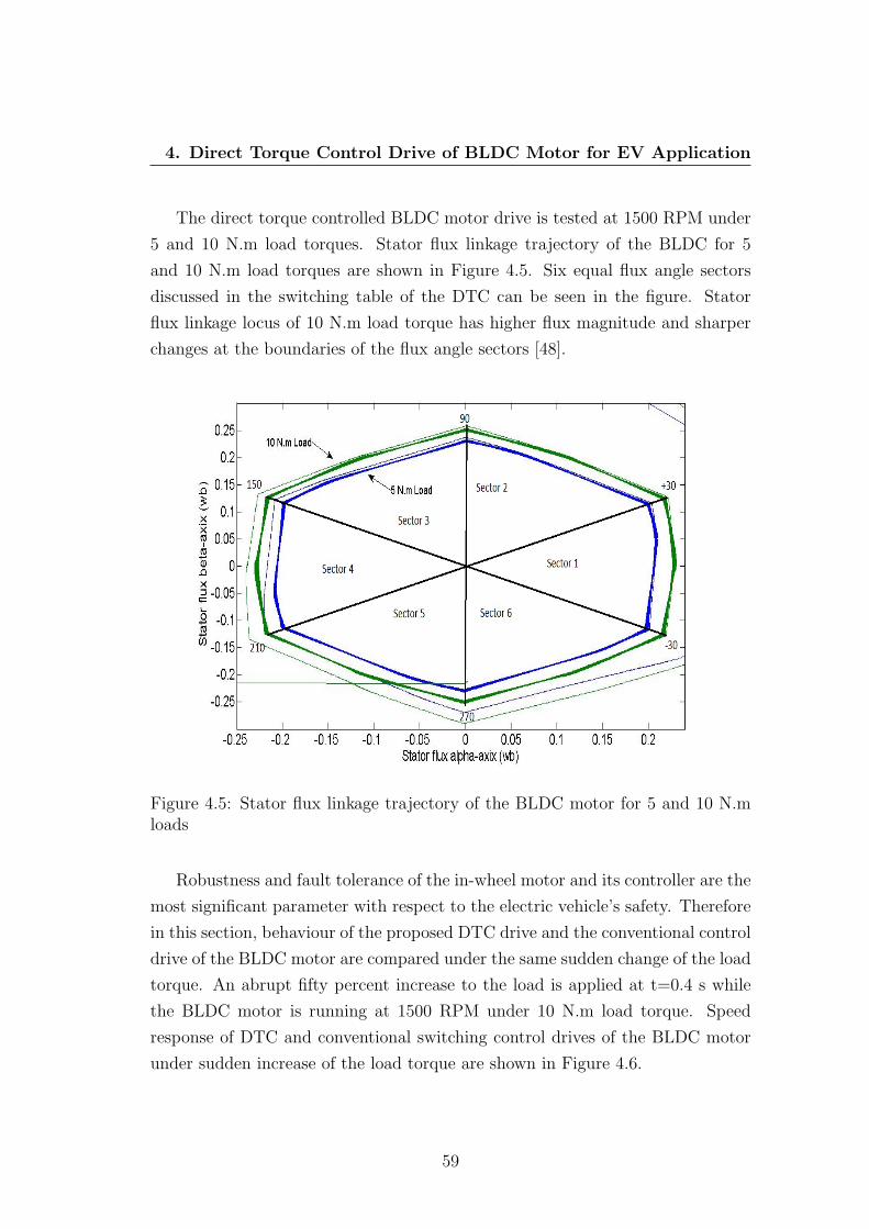
4. Direct Torque Control Drive of BLDC Motor for EV Application
The direct torque controlled BLDC motor drive is tested at 1500 RPM under
5 and 10 N.m load torques. Stator flux linkage trajectory of the BLDC for 5
and 10 N.m load torques are shown in Figure 4.5. Six equal flux angle sectors
discussed in the switching table of the DTC can be seen in the figure. Stator
flux linkage locus of 10 N.m load torque has higher flux magnitude and sharper
changes at the boundaries of the flux angle sectors [48].
Figure 4.5: Stator flux linkage trajectory of the BLDC motor for 5 and 10 N.mloads
Robustness and fault tolerance of the in-wheel motor and its controller are the
most significant parameter with respect to the electric vehicle’s safety. Therefore
in this section, behaviour of the proposed DTC drive and the conventional control
drive of the BLDC motor are compared under the same sudden change of the load
torque. An abrupt fifty percent increase to the load is applied at t=0.4 s while
the BLDC motor is running at 1500 RPM under 10 N.m load torque. Speed
response of DTC and conventional switching control drives of the BLDC motor
under sudden increase of the load torque are shown in Figure 4.6.
59

4. Direct Torque Control Drive of BLDC Motor for EV Application
Figure 4.6: Speed response of the BLDC motor under sudden increase of load
Figure 4.7: Torque response of the BLDC motor under sudden increase of load
60

4. Direct Torque Control Drive of BLDC Motor for EV Application
As can be seen in the figure, the speed response of the BLDC motor for
DTC drive follows the controller reference speed almost fifteen times faster than
conventional switching technique after abrupt change of the load. However speed
fluctuation of the DTC drive is more than the conventional switching technique.
Torque response of DTC and conventional switching control drives of the
BLDC motor under sudden increase of the load torque are shown in Figure 4.7.
As can be seen the torque response of the DTC drive is much faster than the Hall
Effects switching technique of the BLDC motor. Dynamic torque response of the
electric motor plays an important role in the overall stability of the EV when it
is subjected to frequent changes of the load torque. Therefore the DTC drive is
more suitable for in-wheel BLDC motors compared to the conventional control
drive in high performance electric vehicles.
4.5 Experimental Results
Performance of the proposed direct torque controlled BLDC motor is investi-
gated through experiment. A low voltage development board of the microchip
using PIC18F4231 microcontroller is programmed to test the proposed DTC drive
control system on a 24 volts experimental test BLDC motor. The experimental
set-up of the BLDC motor is shown in Figure 4.8. MOSFET switches are used in
VSI drive of the BLDC motor. Specifications of the experimental BLDC motor
is given in Table 4.3 (refer to the hurst motor data-sheet in Appendix B).
Direct torque control drive of the experimental BLDC motor is tested at
2000 RPM (below rated speed of the experimental BLDC motor) under 0.1 N.m
reference torque and for 0.01 hysteresis band limits. Torque characteristics of the
experimental BLDC motor are shown in Figure 4.9. As can be seen, produced
electric torque of the BLDC motor pulsates around 0.1 N.m (load torque) with
the maximum torque ripples amplitude of 0.12 N.m.
61

4. Direct Torque Control Drive of BLDC Motor for EV Application
Figure 4.8: Experimental set-up of the BLDC motor
Table 4.3: Specifications of the Experimental BLDC Motor
Description Value Unit
DC voltage 24 V
Rated Speed 3000 RPM
Rated torque 0.28 N.m
Phase resistance 2.015 Ω
Phase inductance 4.6×10⁻³ H
Inertia 4.43×10⁻⁶ kg-m2
Poles 8 -
62

4. Direct Torque Control Drive of BLDC Motor for EV Application
Figure 4.9: Torque characteristics of the experimental BLDC motor
4.6 Conclusion
Electric vehicles are a viable alternative for the future transportation that does
not emit greenhouses gases into the atmosphere. BLDC motors are commonly
used by auto-mobile manufacturers as a propulsion system of the electric vehicles.
Torque control of the in-wheel BLDC motors is an important factor in overall
safety of the electric vehicles. In this chapter direct torque control switching
technique of the BLDC motor is introduced as a suitable choice for the EV drive
train application. DTC drive model of the BLDC motor is simplified, flux linkage
observation is eliminated, for the constant torque region operation.
The proposed DTC model of the BLDC motor is simulated in Simulink. Sim-
ulation results show that the estimated torque by state observer is as same as the
produced electric torque of the BLDC motor. It is also possible to control the
torque ripples of the BLDC motors by adjusting the hysteresis band limit. Sim-
ulation results show effective reduction of torque ripple amplitude by DTC drive
compared to the conventional control system of the BLDC motor. The proposed
63

4. Direct Torque Control Drive of BLDC Motor for EV Application
DTC drive is tested on a low voltage BLDC motor through the experimental set-
up. Experimental results show effective control of torque and correct performance
of the proposed drive. Developed DTC switching technique of BLDC motor is
capable of minimizing the torque ripples and delivering the smoother mechanical
power to the wheels.
64

Chapter 5
Stability Analysis of a Novel
Sensorless Drive of BLDC Motor
5.1 Chapter Overview
Permanent magnet brushless DC motors have been widely used in traction
applications such as propulsion system of electric vehicles in the last decade. Sen-
sorless control drives of the BLDC motor have been extensively used in industrial
application in recent years. In this chapter a novel sensorless technique based
on back-EMF zero crossing detection (ZCD) of one phase of the BLDC motor is
proposed for EV application. The presented sensorless algorithm is simple and
remarkably reduces sensing circuitry, noise susceptibility and cost of the BLDC
motor control drives. Speed controller of the BLDC motor is a digital pulse width
modulation technique using a Proportional Integral controller. Stability of the
proposed sensorless BLDC motor drive using digital PWM technique is analysed
using Lyapunov stability method. Based on Lyapunov stability criterion a novel
condition for stability analysis of the PWM speed controller is derived. Effective-
ness of the proposed sensorless technique and precision of the introduced stability
analysis condition of the PWM speed controller are proved through simulation
and experiment.
65

5. Stability Analysis of a Novel Sensorless Drive of BLDC Motor
5.2 Introduction
BLDC motors have been used extensively in various industrial applications
such as auto-mobile and aerospace industries in the 21st century. As it is discussed
in previous chapters, BLDC motor is a type of conventional DC motor that is
commutated electronically instead of using brushes. Schematic diagram of a 3
phases, 4 poles, star connected BLDC motor drive is shown in Figure 3.4 on
Page 41. Detecting position of the permanent magnet rotor is the key point
for electronic commutation of the BLDC motor. Position of rotor is normally
detected by three Hall Effect sensors mounted in non-rotating end of motor with
120 electrical degree phase difference. Signal of the Hall Effect sensor is high or
low as the rotor magnetic poles N or S passes near the sensor [32]. Therefore
output of each sensor is high for 180 electrical degree and is low for the next
180 degree according to the rotor position. Correct voltage space vectors for
switching inverter drive of the BLDC motor are chosen by decoding Hall Effect
signals (refer to Table 3.1 on the page 3.1).
Commutation of the BLDC motors using position sensors are much easier than
sensorless methods. However increase of the motor manufacturing cost, problems
due to the sensors breakdown, need of sensors to be mounted accurately that
increase complexity of the manufacturing process, regular need of maintenance,
extra wiring and limited operation of the motor due to temperature sensitivity
of sensors are the main drawbacks of using position sensors to commutate BLDC
motor [11].
Sensorless control drive of the BLDC motors have became popular in some
specific applications such as EV in the last decades. Reduction complexity of the
BLDC motor construction, cost and need of maintenance are immediate advan-
tages of sensorless control. Various sensorless control techniques of the BLDC
motor are reported so far. Back-EMF zero crossing detection, back-EMF in-
tegration, back-EMF harmonic analysis, freewheeling diode conduction of the
unexcited phase and flux linkage based methods are examples of reported sen-
sorless technique of the BLDC motor [7]. However transient time response and
high commutation rates are the main drawbacks of the BLDC motor sensorless
drives [48]. Since the trapezoidal back-EMF permanent magnet synchronous mo-
66
5. Stability Analysis of a Novel Sensorless Drive of BLDC Motor
tors require accurate phase current control and any phase errors in commutation
signals cause significant pulsating torque and increase copper losses in the BLDC
motor [62].
Back-EMF based sensorless methods mainly rely on zero crossing detection
of the phase voltages. There are 120 electrical degree conduction period and
180 electrical degree conduction period switching techniques for VSI drive of the
BLDC motors. There is an unexcited phase, silent phase, winding during each
step in 120 conduction electrical degree mode that is used for Back-EMF ZCD
and rotor positioning in sensorless drives of the BLDC motor [63]. Phase voltages
of the BLDC motor during the silent period is the same as back-EMF voltage
[64]. Since neutral point of the BLDC motor windings is neither provided by the
manufacturer nor stable during high frequency PWM switching; the back-emf
of each phase is detected through the line voltage of the same phase of motor
with respect to the negative terminal of VSI DC power supply [34]. This method
also eliminates unwanted common mode noises on the voltage signal. Therefore
the measured back-EMF voltages does not need filtering and are less susceptible
for switching noise [65]. Filters produce phase delays to the measured voltages
that is dependent to the frequency or the motor speed. Reduction of torque
per ampere capability of the BLDC motor, increase of torque ripples, additional
copper loss, limited speed range operation of the motor, poor signal to noise
ratio during starting time and severe commutation delays at high speeds are the
main disadvantages of filtering phase delays [62][66]. Sensing line voltages of the
BLDC motor with respect to the negative terminal of DC link of VSI also avoids
filtering delay problems [67]; however operation of the BLDC motor at low speeds
is the main drawback of this method [7]. Difficulties of back-EMF sensing at low
speeds (proper rotor positioning is not possible below 20% of the rated speed) and
position detection errors during quick acceleration or deceleration of the BLDC
motor are the general problems in ZCD of the back-EMF sensing based sensorless
methods [65].
Sensorless techniques based on zero crossing detection of line voltage differ-
ences of the BLDC motor is introduced [11][68]. Three phase line voltages of
the BLDC motor have to be measured separately in the proposed methods that
increase the measuring circuitry. There is 30 electrical degree phase delay be-
67

5. Stability Analysis of a Novel Sensorless Drive of BLDC Motor
tween ZCD points and commutation points at each phase of the BLDC motor.
The proposed method by Kim et al. [68] is much simpler because it does not
need implementation of electrical degree phase delay after ZCD points. However
the BLDC motor operation at low speeds is a drawback for the both proposed
sensorless drives.
Digital PWM control and hysteresis current control techniques are more com-
mon in the BLDC motor speed controllers than sliding mode control technique
[69]. Pulse width modulation technique is used for speed control in this chap-
ter. High frequency PWM signal is superimposed on the neutral point of star
connected windings and induce noise to the measured line voltages. Back-EMF
integration and third harmonic voltage integration are introduced to reduce the
inverter switching noise effects and avoid using filters in the BLDC motor sen-
sorless drives [66]. In the first method, commutation points are detected through
back-emf ZCD of the unexcited phase of the motor as soon as the voltage integral
pass a predefined threshold [64]. However accurate control and poor performance
of the BLDC motor at low speeds are weaknesses of back-EMF integration ap-
proach [11][66]. The other main problem of this technique is DC drift errors
produced by analogue integrators, as it is discussed in Chapter 4, specifically at
low speeds [64].
Addition of three phase voltages of the BLDC motor results in the third har-
monic and multiples of the third harmonic components due to the symmetric
three phase star connected windings. Zero crossing of integrated third harmonic
signal occurs at the exact current commutation points of the BLDC motor [69].
This technique has a wider speed range compare to the back-EMF integration
method. Need of the neutral point voltage of the motor, variation of the winding
inductance due to the rotation of permanent magnet motor (which needs to be
constant in this method), low amplitude of the third harmonic components at
low speeds, variation of magnitude and phase of harmonic components due to
magnetic saturation and unbalanced situation in the surface mounted permanent
magnet machines are the main limitations of the BLDC motor third harmonic
back-EMF based sensorless drives [7][70]. An application-specific integrated cir-
cuit (ASIC) based controller using third harmonic integration method with a
phase locked-loop (PLL) is proposed to improve the BLDC motor performance at
68

5. Stability Analysis of a Novel Sensorless Drive of BLDC Motor
ultra-high speeds [71]. The current phase delay is eliminated and the BLDC mo-
tor commutation is improved by the proposed technique. Sensorless commutation
of the BLDC motor based on conducting status of anti-parallel connected free-
wheeling diode of the unexcited phase has a wide speed range and simple starting
procedure [65]. Position detection errors during transient state, additional inde-
pendent voltage sources, need for the proper isolation mechanism, complexity of
algorithm and high cost of the controller drive are the main drawbacks of this
method [66][72].
Switching signals in flux linkage based sensorless methods, same as the direct
torque control discussed in Chapter 4, are extracted through flux linkage magni-
tude and flux angle of the BLDC motor. Flux linkage magnitude and flux angle
values are calculated from the motor voltage and current signals. Flux based
sensorless methods have significant flux estimation errors at low speeds [34]. Kim
and Ehsani are reported a speed independent method to solve the flux estima-
tion errors of the flux based sensorless methods of the BLDC motor at low speed
[7]. The proposed method is based on the derivative of phase currents and needs
digital implementation, thus it is susceptible to noise [11].
In this chapter, a simple sensorless commutation technique is proposed for
the BLDC motor based on the ZCD of back-EMF of one phase of motor instead
of measuring back-EMF of all the three phases. Back-EMF sensing circuitry
and cost of the sensorless drive of BLDC motor is effectively reduced in the pro-
posed method. Back-EMF of BLDC motor is sensed through line voltage of one
phase of motor with respect to the negative terminal of DC bus of VSI. There-
fore the sensed back-EMF voltage does not need filtering and is less susceptible
to the noise. The proposed commutation technique also can be used as a re-
medial strategy in the Hall Effect sensors fault tolerant control system (refer to
Chapter 6, Section 6.5). The proposed sensorless technique is suitable to design
integral in-wheel BLDC motor for electric vehicles due to its simplicity and low
electromagnetic interference (EMI) [34].
Back-EMF of the BLDC motor is directly proportional to the rotor speed,
therefore back-EMF based sensorless methods have a poor performance at low
speeds. The main problem raises up at start up of the BLDC motor where there
is no back-EMF at stand still situation. Therefore a starting procedure is needed
69
5. Stability Analysis of a Novel Sensorless Drive of BLDC Motor
to speed up the BLDC motor to a point that is possible to measure the back-
EMF voltage and implement the sensorless algorithm [65][73]. Various start-up
methods are reported for the sensorless BLDC motor drives [73][74][75][76]. Start
up techniques of the sensorless BLDC motor drives are not within the scope of this
chapter. Starting algorithm reported by Iizuka et al. [74] is used in the proposed
method in this chapter. The discussed sensorless commutation technique in this
chapter is applicable after prepositioning and start up process.
Digital pulse width modulation technique is used for speed control of the
BLDC motor. Stable performance of the motor and its drive is critical and im-
portant in applications such as the electric vehicles that any instability of the
system may put life of the passengers in danger. Up to the knowledge of the
author, there are not much reported research works on stability analysis of the
PWM control drives of BLDC motors so far. Milivojevic et al. [77] have discussed
stability analysis of FPGA based PWM controller drive of the BLDC motor ac-
cording to the Lyapunov stability method. Merits and demerits of the proposed
stability analysis method are discussed in details in section 5.4. The introduced
stability analysis method is improved and a new equation is introduced to analyse
the stability of the BLDC motor drives using PWM speed controller for EV appli-
cation. The discussed stability analysis method is validated through simulation
and experimental results. Some of the presented simulation and experimental
results in this chapter have been published by Tashakori et al. [34].
5.3 Proposed Sensorless Technique for BLDC
Motor
A comprehensive knowledge of the BLDC motor performance such as exact
information about sensors output signals with respect to the permanent magnet
rotor position and correlation between the back-EMF, line voltages and commu-
tation points of the BLDC motor is needed to develop a sensorless algorithms.
Equivalent electrical circuit of a three phase star connected BLDC motor and
VSI drive are shown in Figure 5.1.
70

5. Stability Analysis of a Novel Sensorless Drive of BLDC Motor
Figure 5.1: Equivalent electrical circuit of the BLDC motor drive
Terms Va, Vb and Vc are referred to the line voltages of the BLDC motor, Vn
is the neutral point voltage and Vdc is the DC bus voltage of the inverter. Ideal
commutation signals, terminal and back-EMF voltages of the BLDC motor are
shown in Figure 5.2. As can be seen in the figure, at each instant of time only
two switches of inverter is conducting according to the permanent magnet rotor
position (refer to the Table 3.1 on the page 40). It means that two phases are
conducting and current of one phase is zero, therefore it is possible to measure
the back-EMF voltage through the unexcited phase. Consider phase B and C are
conducting and phase A is the silent phase. Therefore,
ia + ib + ic = 0⇒ ib = −ic and ia = 0 (5.1)
Resistance and inductance of stator windings are assumed to be constant.
Magnetic circuit saturation and losses are also ignored in calculations. Then
71

5. Stability Analysis of a Novel Sensorless Drive of BLDC Motor
Figure 5.2: Ideal commutation signals, terminal and back-EMF voltages of theBLDC motor
terminal voltage equations of the BLDC motor can be expressed as [34],
Va = Ea + Vn (5.2)
Vb = Rib + Ldibdt
+ Eb + Vn (5.3)
Vc = Ric + Ldicdt
+ Ec + Vn (5.4)
where Eb = −Ec and Va + Vb = Vdc, therefore the neutral point voltage can be
72

5. Stability Analysis of a Novel Sensorless Drive of BLDC Motor
calculated by adding equations (5.3) and (5.4),
Vn =VDC
2(5.5)
Substituting the calculated neutral voltage in equation (5.2), terminal voltage
of the unexcited phase can be written as,
Va = Ea +VDC
2(5.6)
Zero crossing points of back-EMF can be detected from terminal voltage of
the floating phase through equation (5.6). Thus zero crossing points of back-EMF
voltage (Ea = 0) occur when the corresponding floating terminal voltage is [72],
Va =VDC
2(5.7)
Therefore as it is also shown in the Figure 5.2, zero crossing points of back-
EMF voltage of the unexcited phase happen when terminal voltage of the corre-
sponding phase of the BLDC motor is equal to half of the DC power supply of
inverter. On the other words as can be seen in the figure, commutation instants
of the BLDC motor occur 30 electrical degree after the ZCD points and there
is the exact 120 electrical phase shift between commutation signals of different
phases in the BLDC motor.
Knowing the exact back-EMF zero crossing points of one phase is enough
to generate commutation signals of the other two phases of the BLDC motor.
Therefore in this chapter an optimized sensorless commutation technique of the
BLDC motor is introduced based on back-EMF zero crossing detection of one
phase of motor. In the proposed method line voltage of only one phase of the
BLDC motor is sensed with respect to the VSI DC link instead of measuring all
three terminal voltages [34]. A reference commutation signal is generated based
on ZCD of the line voltage. The reference commutation signal is set to logic one
at zero crossing points of rising edge and it is set to logic zero at zero crossing
points of falling edge of the measured line voltage. Then commutation signals
of all three phases are generated according to their correlated electrical degree
delays from the reference signal.
73

5. Stability Analysis of a Novel Sensorless Drive of BLDC Motor
A simple formula is introduced to calculate time of the electrical degree delay
with respect to the speed of the BLDC motor. If speed of the motor is constant
during the commutation intervals (controller keeps the motor speed constant) and
the number of motor pole pairs (Ratio of electrical degree to mechanical degree
rotation of rotor) is known; therefore the time needed for one electrical degree
rotation of the rotor can be calculated in seconds as below [34],
Tone electrical degree =60
P2
(360× ωref )(5.8)
Where P is the number of the motor poles and ωref is the reference speed in
RPM. Practically it is easy and convenient to calculate and implement the elec-
trical degree delays as time delays in microcontrollers. Schematic diagram of the
proposed BLDC motor sensorless drive is shown in Figure 5.3.
Figure 5.3: Schematic diagram of the proposed BLDC motor sensorless drive
74

5. Stability Analysis of a Novel Sensorless Drive of BLDC Motor
5.4 Stability Analysis of Digital PWM Controller
Hysteresis current control and pulse width modulation control techniques are
the most widely used methods in the BLDC motor speed control drives [69][78].
Speed of the BLDC motor is directly proportional to the applied terminal voltages
of the motor. A three phase voltage source inverter is used to supply the BLDC
motor in the six-step algorithm. Variable DC link inverter and PWM technique
are commonly used techniques for adjusting the average output voltage of the
VSI. In the first method voltage of the DC power supply of the inverter changes
according to the motor speed. In PWM technique, a high frequency duty cycle
controlled signal is added to switching signals of the VSI. By adjusting the duty
cycle of the PWM signal according to the motor speed, it is possible to the applied
voltages to the BLDC motor and consequently the speed of the motor. The PWM
signal can either be multiplied to the switching signal of upper switches, lower
switches, or all six switches of the VSI. Pattern of the applied line voltage to the
BLDC motor varies for different PWM switching mode [5]. In this chapter, PWM
signals are applied to the upper switches of the VSI in the simulation model and
experimental set-ups.
A digital control scheme for the BLDC motor drives is reported by Sathyan
et al. [78] based on the two predetermined duty cycle values (state high, DH ,
and state low, DL, PWM duty cycles) for PWM signal. Controller switches
between state high and state low according to the BLDC motor speed. Predefined
duty cycle values limit the functionality of the controller for the variable speed
applications such as electric vehicle. A proportional and integral controller is
used to adjust the duty cycle of PWM signal with respect to the speed error.
Ideally one duty cycle is chosen by PI controller, (0 ≤ D ≤ 1), at any particular
reference speed. However practically the controller adjusts duty cycle values in
close boundaries of the ideal duty cycle instead of having two predefined states
[34]. Therefore there is no need to know desired duty cycle states for different
speed operations and it is suitable for the application with the frequent change
of speed such as the in-wheel motors.
Stable performance of the BLDC motor control drive is critical in application
such as EV with respect to the safety point of views. In this chapter stability
75

5. Stability Analysis of a Novel Sensorless Drive of BLDC Motor
of the proposed sensorless BLDC motor drive using digital PWM controller is
analysed through Lyapunov’s second method stability criterion (refer to the Ap-
pendix A, Section Four). Milivojevic et al. [77] are discussed stability analysis
of a FPGA-based controller of the BLDC motor using PWM technique based on
Lyapunov stability method. Stability analysis results in introducing limit con-
ditions for DHmax and DLmin (two predefined duty cycle states) that define the
stable operation range of the BLDC motor drive. Effect of the load torque and
rate of change of load torque are not considered in the analyses that are impor-
tant in EV application due to the frequent change of load on tires. The effect of
load torque is also considered in the discussed stability analysis in this chapter.
Speed error is considered as the structural variable or switching surface of the
PWM controller to apply the Lyapunov stability condition.
s = ωref − ω (5.9)
Candidate Lyapanuv function introduced in [77] is used for stability analysis
of digital PWM controller.
C(s(x)) =1
2sT (x)s(x) (5.10)
According to the Lyapunov stability criterion, PWM controller is stable equi-
librium if the Lyapunov candidate function is locally positive at s(x) = 0, then
its derivative should be locally negative (dCdt< 0⇒ ∂C
∂s∂s∂t< 0). In the other word
the control system is Lyapunov stable if s and its first derivative s, have opposite
signs [34].
Mathematical equations of electrical and mechanical systems of the BLDC
motor can be expressed as,
DVDC = Ri+ Ldi
dt+Keω (5.11)
Kti− Tl = jdω
dt+ βω (5.12)
From now on it is assumed that torque constant and back-EMF constant are
equal (K) in this chapter. A second order differential equation with ω as the
76

5. Stability Analysis of a Novel Sensorless Drive of BLDC Motor
state variable can be derived by substituting the current value from equation
(5.12) into the equation (5.11).
d2ω
dt+ a1
dω
dt+ a2ω − b1D + b2Tl + b3
dTldt
= 0 (5.13)
where constants a1, a2, b1, b2, b3 are defined as below to simplify the equation
(5.13).
a1 = (βL+ jR
jL) (5.14)
a2 = (βR +K2
jL) (5.15)
b1 =KVDCjL
(5.16)
b2 =R
jL(5.17)
b3 =1
j(5.18)
State variable x in the candidate function represents speed of the motor [77].
Therefore derivative of switching surface function is,
s =∂s
∂ω
dω
dt= −dω
dt(5.19)
Solving equation (5.13) for derivative of speed and substitute the result in
equation (5.19) results in,
s = a1ω + a2
∫ω.dt− b1
∫D.dt+ b2
∫Tl.dt+ b3Tl (5.20)
According to the Lyapunov stability criterion, if s is negative (actual speed is
more than reference speed) then s should be positive and if s is positive (actual
speed below reference speed) s should be negative. Therefore limit conditions of
the digital PWM speed controller’s duty cycle for system to be Lyapunov stable
77

5. Stability Analysis of a Novel Sensorless Drive of BLDC Motor
are [34],
a1b1
dω
dt+a2b1ω +
b2b1Tl +
b3b1
dTldt
> D − ε if s < 0 (5.21)
a1b1
dω
dt+a2b1ω +
b2b1Tl +
b3b1
dTldt
< D + ε if s > 0 (5.22)
Ideal performance of the digital PWM controller concludes to have a constant
duty cycle if the actual speed of the BLDC motor is exactly as same as the
reference speed (dωdt
= 0). Furthermore if it is assumed that there is no load
torque change during operation of the motor (dTldt
= 0); then equations (5.21) and
(5.22) can be merged as,
D = (βR +K2
KVDC)ωref + (
R
KVDC)Tl (5.23)
Duty cycle condition for stability analysis of the digital PWM controller for
the constant torque and speed applications is expressed by equation (5.23). As the
controller does not work ideal in practice and the motor speed fluctuates around
the reference speed; therefore the duty cycle values chosen by the PI controller
oscillate around the ideal duty cycle value expressed by equation (5.23). However
change of the speed and load torque must be considered for stability analysis of
the BLDC motor in the electric vehicle that torque and speed parameters changes
continuously due to frequent start, stop, acceleration and deceleration.
5.5 Simulation Results and Discussion
The proposed back-EMF based sensorless commutation technique of the BLDC
motor is simulated in Simulink. The BLDC motor specifications used in the
simulation model are given in Table 2.5 on page 22. The reference commutation
signal is generated based on the back-EMF ZCD of the measured line voltage
of phase A of the BLDC motor. The line voltage of phase A is measured with
respect to the negative terminal of the VSI DC link. An embedded Matlab code
has been written to detect zero crossing points of the back-EMF based on the
discussed method. The reference commutation signal is set to logic one at the
78

5. Stability Analysis of a Novel Sensorless Drive of BLDC Motor
rising ZCD point and is set to logic zero at the falling ZCD point. The main
three commutation signals of the BLDC motor are generated by implementing
the electrical degree delays calculated from the equation (5.8). Commutation
signal of the measured phase has 30 electrical degree delay and the other two
commutation signals have 150 and 270 electrical degree delays from the reference
signal respectively.
The generated commutation signals are decoded and the correct switching
signals are applied to the inverter. MOSFET switches are used to model the three
phase voltage source inverter. The inverter is switched in a six-step sequence to
direct the current to the three-phase BLDC motor. Digital PWM speed controller
is implemented to control speed of the motor. A Matlab file is embedded in
Simulink model to generate a duty cycle controlled PWM signal. Duty cycle
of the PWM signal is determined by a PI controller based on the speed error.
Duty cycle controlled PWM signals is multiplied to switching signal of the upper
switches in each phase of the VSI. The start-up algorithm proposed by Iizuka
et al. [74] is used to run the BLDC motor up to the point that the proposed
sensorless drive is able to detect the back-EMF voltage and control the motor.
The proposed sensorless drive simulation model of the BLDC motor is tested
for 2000 RPM reference speed of the PWM controller under 5 N.m torque load.
Line voltage of phase A, corresponding back-EMF of phase A and zero crossing
detected points by controller are shown in Figure 5.4 [34]. As can be seen zero
crossing points of the back-EMF occurs exactly when the line voltage value pass
through half of the inverter DC supply. There are two zero crossing points during
each electrical cycle of phase voltage; one at rising edge and the other at the falling
edge of the line voltage. These ZCD points are the reference for the commutation
signal to set high and low respectively.
Zero crossing points and the commutation signal of phase A of the BLDC
motor are shown with respect to the electrical degree in Figure 5.5 [34]. As it
is magnified in the figure, the commutation signal of phase A is delayed exactly
30 electrical degree from back-EMF zero crossing points. Commutation signal of
each phase is logic one for 180 electrical degree and logic zero for the other 180
electrical degree during one full electric rotation of the BLDC motor.
79
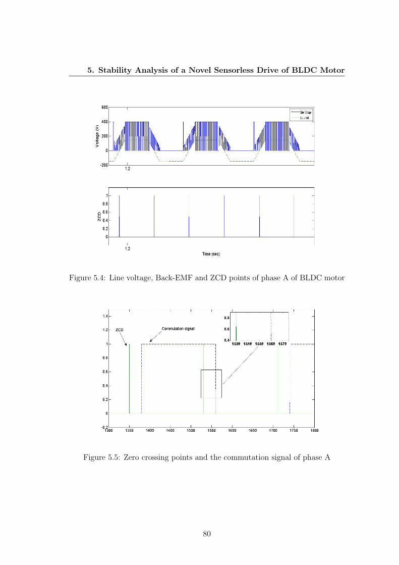
5. Stability Analysis of a Novel Sensorless Drive of BLDC Motor
Figure 5.4: Line voltage, Back-EMF and ZCD points of phase A of BLDC motor
Figure 5.5: Zero crossing points and the commutation signal of phase A
80

5. Stability Analysis of a Novel Sensorless Drive of BLDC Motor
Current and commutation signal of phase A of the BLDC motor are shown
in Figure 5.6. As can be seen in the figure, current flows at the same time
of rising edge of the corresponding commutation signal. At each commutation
sequence one phase is connected to the positive terminal of inverter DC link
(current entering the phase winding), and one phase is connected to the negative
terminal of inverter DC link (current exiting the phase winding) and the third
phase is not excited (current is zero). Therefore as can be seen in the figure, phase
current has one positive cycle, one negative cycle and two unexcited periods (zero
current) during one full electrical rotation of the BLDC motor. Zero crossing
points of back-EMF occur in the period that phase current is zero.
Figure 5.6: Current, commutation signal and ZCD points of phase A
Speed response of the BLDC motor sensorless drive and chosen duty cycles
by PI controller are shown in Figure 5.7 [34]. By considering the operation of the
BLDC motor under constant speed and load torque, the ideal PWM duty cycle
percentage calculated from the equation (5.23) according the motor parameters
and 2000 RPM reference speed is 75%. As can be seen PI controller has chosen
duty cycles around the ideal value.
81
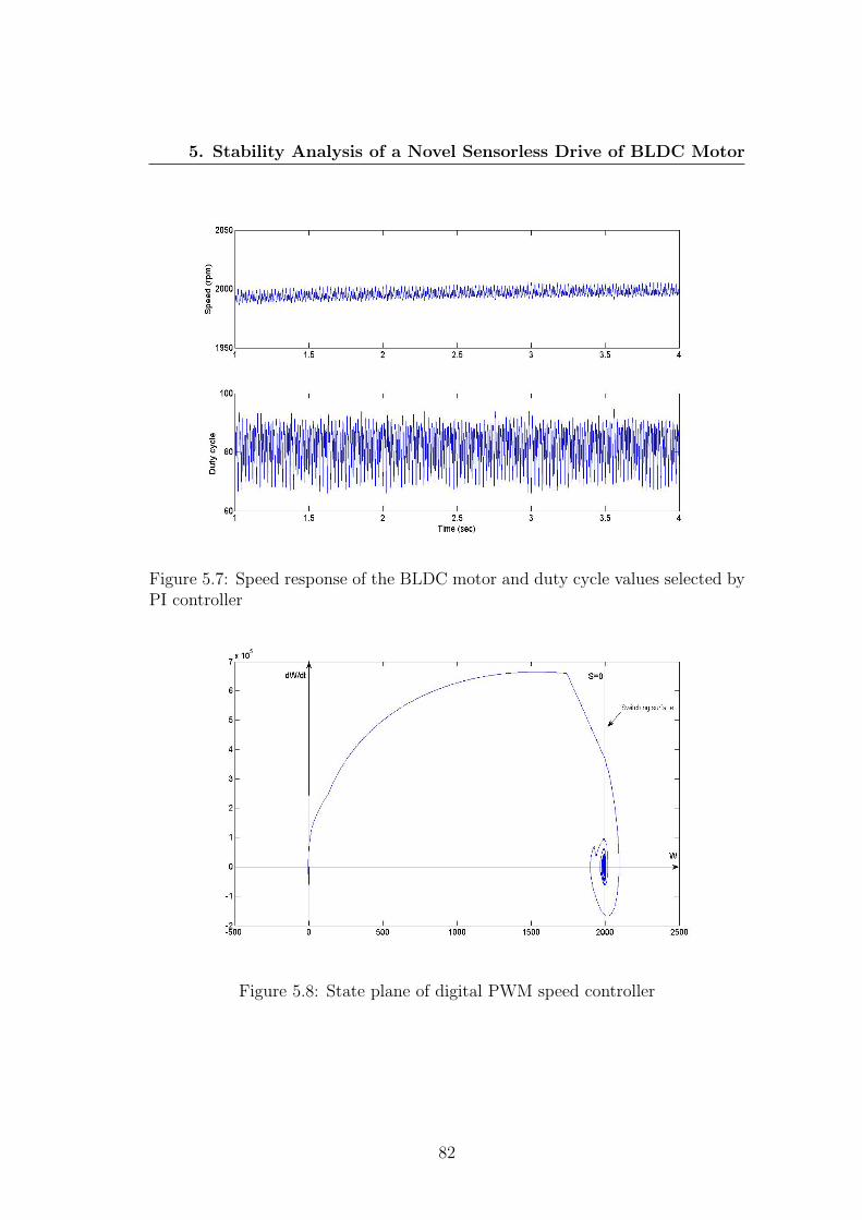
5. Stability Analysis of a Novel Sensorless Drive of BLDC Motor
Figure 5.7: Speed response of the BLDC motor and duty cycle values selected byPI controller
Figure 5.8: State plane of digital PWM speed controller
82

5. Stability Analysis of a Novel Sensorless Drive of BLDC Motor
State plane of the PWM speed controller is plotted in Figure 5.8. It can
be seen that the PWM controller keeps the BLDC motor speed at the stable
equilibrium around the switching surface at 2000 RPM. Therefore the proposed
sensorless drive of the BLDC motor using digital PWM speed controller is Lya-
punov stable.
The BLDC motor model is tested in brake condition of an electric vehicle
from constant speed and torque operation to full stop position. Brake condition
is chosen to study the proposed sensorless drive using PWM speed controller
performance under variable speed and load torque conditions. The BLDC motor
model is run at 2000 RPM under 5 N.m torque load (constant speed and torque
operation) and a soft brake is applied at t = 1 s to the motor and vehicle is
supposed to stop at t = 3 s. Brake duration is two seconds for the electric
vehicle to stop completely (zero speed). It is assumed that brake is applied both
electrically, decreasing reference speed of controller to zero and mechanically,
increasing the load torque on the wheels. Speed and torque characteristics of the
BLDC motor during brake condition are shown in Figure 5.9 [34].
Figure 5.9: Speed and torque characteristics of the BLDC motor during brake
83

5. Stability Analysis of a Novel Sensorless Drive of BLDC Motor
The BLDC motor has a stable speed response and speed follows the reference
speed of the controller. Produced electric toque and torque ripples of the BLDC
motor is increased after the mechanical brake is applied to the motor. Maximum
torque ripples occurs when the BLDC motor speed is around 1300 RPM. The
produced electric torque of the motor is zero when vehicle is fully stopped.
Ideal, estimated and chosen duty cycle values by the PI controller during the
brake condition are shown in Figure 5.10 [34]. The first graph shows the ideal
duty cycle values calculated from equation (5.23). Changes of speed and load
torque of the BLDC motor are not considered in the first graph. The second
graph shows the estimated duty cycle values calculated from equations (5.21)
and (5.22). Changes of speed and load torque of the BLDC motor are considered
in the second graph. The third graph shows the simulation results for duty cycle
values chosen by the PI controller. As can be seen in the figure, duty cycle
values of the simulation results are following pattern of the estimated duty cycle
values. Therefore simulation results validate correctness of the equations (5.21)
and (5.22) for variable speed and torque operation condition of the BLDC motor.
Figure 5.10: Duty cycle values during the brake condition
84

5. Stability Analysis of a Novel Sensorless Drive of BLDC Motor
State plane of the PWM speed controller during the brake condition is plotted
in Figure 5.11. As can be seen in the figure, the system remains at the stable
equilibrium point around the reference speed at each instant of time during the
brake condition. Simulation results show that the PI controller has selected the
correct duty cycle values to keep the BLDC motor drive stable during the brake
condition.
Figure 5.11: State plane of digital PWM speed controller during the brake
5.6 Experiment Results
Effectiveness of the proposed sensorless drive of the BLDC motor using digital
PWM speed controller is investigated through experiment. Experimental test rig
of the BLDC motor is same as reported in Chapter 4, Section 5. A low voltage de-
velopment board of microchip using PIC18F4231 microcontroller is programmed
to test the proposed sensorless BLDC motor drive. PIC microcontroller is also
programmed to implement the digital PWM speed controller of the BLDC motor
in a closed loop scheme. One of the in-built Hall Effect sensors of the motor is
85
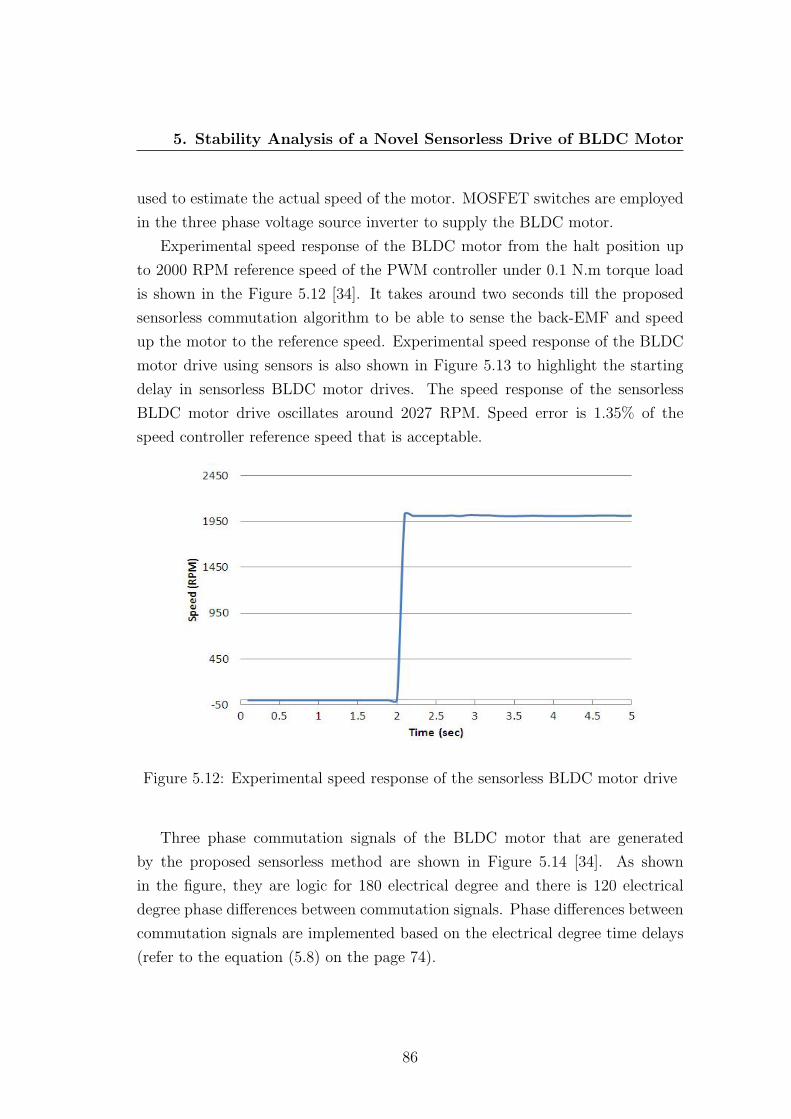
5. Stability Analysis of a Novel Sensorless Drive of BLDC Motor
used to estimate the actual speed of the motor. MOSFET switches are employed
in the three phase voltage source inverter to supply the BLDC motor.
Experimental speed response of the BLDC motor from the halt position up
to 2000 RPM reference speed of the PWM controller under 0.1 N.m torque load
is shown in the Figure 5.12 [34]. It takes around two seconds till the proposed
sensorless commutation algorithm to be able to sense the back-EMF and speed
up the motor to the reference speed. Experimental speed response of the BLDC
motor drive using sensors is also shown in Figure 5.13 to highlight the starting
delay in sensorless BLDC motor drives. The speed response of the sensorless
BLDC motor drive oscillates around 2027 RPM. Speed error is 1.35% of the
speed controller reference speed that is acceptable.
Figure 5.12: Experimental speed response of the sensorless BLDC motor drive
Three phase commutation signals of the BLDC motor that are generated
by the proposed sensorless method are shown in Figure 5.14 [34]. As shown
in the figure, they are logic for 180 electrical degree and there is 120 electrical
degree phase differences between commutation signals. Phase differences between
commutation signals are implemented based on the electrical degree time delays
(refer to the equation (5.8) on the page 74).
86

5. Stability Analysis of a Novel Sensorless Drive of BLDC Motor
Figure 5.13: Experimental speed response of the BLDC motor drive using sensors
Figure 5.14: Generated commutation signals by sensorless drive of BLDC motor
87

5. Stability Analysis of a Novel Sensorless Drive of BLDC Motor
PWM switching signals that are applied to the upper side switches of the VSI
are shown in Figure 5.15 [34]. The Ideal duty cycle percentage calculated from
the equation (5.23) based on the experimental motor specification and operation
condition is 60.31%. As shown in figure, duty cycle values chosen by controller
vary from 47% to 67% that are in the close boundary of the ideal duty cycle.
Figure 5.15: PWM switching signals applied to the upper side switches of VSI
Line voltage and corresponding generated commutation signal of the phase
C of sensorless drive of the BLDC motor are shown in Figure 5.16. As can
be seen phase C line voltage of the motor is exactly in the same phase with
the corresponding generated commutation signal. Experimental results prove
effectiveness and stable performance of the sensorless drive of the BLDC motor
using digital PWM speed controller.
Performance of the digital PWM speed controller is also studied in the context
of a light weight electric vehicle. The proposed PWM speed controller is applied
to the in-wheel BLDC motors of the concept four wheel drive electric vehicle.
The in-wheel BLDC motor set-up and the concept light weight four wheel drive
EV are shown in Figure 5.17.
88

5. Stability Analysis of a Novel Sensorless Drive of BLDC Motor
Figure 5.16: Line voltage and commutation signal of the phase C of BLDC motor
Figure 5.17: The in-wheel BLDC motor set-up in a light weight EV
89

5. Stability Analysis of a Novel Sensorless Drive of BLDC Motor
Four similar three phase in-wheel BLDC motors designed for electric motor
cycle application are used as the drive train of the concept EV. Specifications of
the in-wheel BLDC motors are given in Table 3.3 on the page 46. Permanent
magnet rotor position detection of the in-wheel motors are based on inbuilt Hall
Effect sensors. Each in-wheel motor has its own individual control drive; however
all of the motors operate with the same speed controlled by the acceleration pedal
of the vehicle. Acceleration pedal provide a control analogue voltage signal to
the speed controller drive of in-wheel BLDC motors. The reference speed control
input voltage varies from 0.7 volts for zero speed to 3.6 volts for the full speed
rotation. In-built drum brakes of the motor hubs are used as mechanical brake of
the electric vehicle. Four 12 volts lead-acid batteries are used to supply inverters
of the in-wheel motors in the vehicle.
The concept light weight four in-wheel drive EV is tested for three different
speed operating condition of the in-wheel BLDC motors on a flat road. Line volt-
age and corresponding commutation signal of one of the in-wheel BLDC motors
at different operating condition are shown in Figures 5.18.
Levels of the reference input voltage to the speed controllers provided by the
acceleration pedal are 1.7 volts at low speed, 2.8 volts at moderate speed and 3.6
volts at full load speed operating conditions. In-wheel BLDC motors drive 6 Amps
at full speed operating condition. Therefore according to the manufacturer data-
sheet, the in-wheel motors are producing 2.93 N.m torque at 546.7 RPM. The
BLDC motor line voltages are measured with respect to the negative terminal
of the inverter DC power supply. As can be seen in the figure, duty cycle of
the PWM signal increases based on the input reference speed of the controller.
At full speed operating condition duty cycle of the PWM signal is 100% and
the maximum possible voltage is applied to the in-wheel motors. Experimental
results confirm the correct and stable performance of the proposed digital PWM
speed controller of the BLDC motor.
90

5. Stability Analysis of a Novel Sensorless Drive of BLDC Motor
Figure 5.18: Line voltage and commutation signal of the in-wheel BLDC motorat different operating condition of the light weight EV
91

5. Stability Analysis of a Novel Sensorless Drive of BLDC Motor
5.7 Conclusion
Sensorless commutation techniques of the BLDC motors have been widely used
in industrial applications in recent years. An optimized sensorless commutation
technique based on zero crossing detection of back-emf voltage of only one phase
of the BLDC motor is discussed in this chapter. In this method back-EMF zero
crossing points are detected through the measured line voltage of one phase of
the motor with respect to the negative terminal of the VSI DC link. Measuring
only one phase voltage of the BLDC motor instead of all three phase voltages,
remarkably reduce the cost, noise susceptibility, sensing components and wiring of
the motor drive. The proposed sensorless method is simulated and tested through
the experiment. Simulation and experimental results prove correct and stable
performance of the proposed sensorless drive of the BLDC motor. Simplicity, low
cost, low noise susceptibility and ease of implementation of the control technique
on a single chip microcontroller or a digital signal processor are advantages of the
proposed sensorless commutation method of the BLDC motor as the drive train
of high performance electric vehicles.
A digital PWM switching technique is implemented to control speed of the
proposed sensorless BLDC motor drive in a closed loop scheme. A PI controller
is utilized to select the duty cycle of the PWM controller instead of setting two
predefined duty cycle values. Stability of the proposed sensorless drive of the
BLDC motor using digital PWM speed controller is analysed through Lyapunov
second method. Stability analysis results in deriving a novel condition for duty
cycle of the PWM signal based on the motor parameters and operating condition
of the motor such as speed and load torque. Validity of the presented stabil-
ity analysis condition is verified through simulation and experiment. Effective
performance of the digital PWM speed controller is also tested in a light weight
electric vehicle using four in-wheel BLDC motors. Experimental results show the
stable performance of the electric vehicle using digital PWM speed controllers in
different operating condition.
92

Chapter 6
Fault Diagnosis of the BLDC
Motor Drive for EV Application
6.1 Chapter Overview
Safe operation of electric vehicles is of the prime concerns in automotive in-
dustry. Various Fault Tolerant Control Systems have been developed for electric
motors to diagnose and handle the motor faults and maintain the motor per-
formance in post-fault condition in the last decades. Implementing FTCS’s in
control drives of the in-wheel BLDC motors increase reliability, robustness and
safety of the electric vehicles. In this chapter, two fault tolerant control systems
are proposed to handle inverter switch faults and position sensors (Hall Effect
sensors) failure in the BLDC motor drives. Fault diagnosis in both proposed
FTCS’s are based on Discrete Fourier Transform (DFT) analysis of line voltages
of the BLDC motor. A four wheel drive EV using in-wheel BLDC motors is mod-
elled to study and analyse the EV performance under various drive train fault
conditions. Simulation results show instability of the electric vehicle immediately
after inverter open circuit switch fault occurrence.
A BLDC motor drive is modelled in Simulink to study the motor performance
under fault conditions. The BLDC motor model was validated by experimental
data under no fault condition. Various VSI switch faults and Hall Effect sensor
faults are applied to the validated BLDC motor model. Expert systems are de-
93

6. Fault Diagnosis of the BLDC Motor Drive for EV Application
signed to detect and identify various VSI switch faults and Hall Effect position
sensors failure. Multidimensional fault diagnosis knowledge based tables are de-
veloped by analysing simulation results of the BLDC motor model under various
fault conditions. The proposed fault diagnosis systems are capable of detecting
fault occurrence and identify faulty switch or faulty sensor. Simple strategies are
recommended to remove the faults and keep the BLDC motor drive operation in
post-fault condition. Simulation results and developed knowledge based tables
are validated through experimental data. The proposed fault tolerant control sys-
tems are simple, do not need excessive computations and can be executed with
the main control program of the BLDC motor.
6.2 Introduction
BLDC motors are popular as drive train in traction applications such as hybrid
electric vehicles and pure electric vehicles. Stable motor operation is important on
the overall EV drive train performance and directly effects on safety of the vehicle.
Control of the BLDC motor mainly depends on the accurate detection of the
permanent magnet rotor position that leads to choose the correct voltage space
vectors to switch voltage source inverter and supply the BLDC motor. Therefore
any malfunction of the position detecting sensors or the VSI switches degrade the
BLDC motor performance. Three Hall Effect sensors with 120 electrical degree
phase difference are used to detect rotor position of the BLDC motor in simulation
model and experimental test rig in this chapter.
This chapter presents two novel fault tolerant control systems for inverter
switch faults and position sensors failure in the BLDC motor drives. The pre-
sented FTCS’s are focused on the three phase star connected BLDC motors. Fault
tolerant control systems for the four-phase, five-phase and six-phase BLDC mo-
tors are the prospective potential research studies. Overall model of a 3 phases,
4 poles star connected BLDC motor and its VSI drive are shown in Figure 6.1
[79].
As shown in the figure, control system and variable voltage source inverter
are main sections of the BLDC motor drives. Control system is responsible for
decoding and choosing the three phase inverter switching signals to commutate
94

6. Fault Diagnosis of the BLDC Motor Drive for EV Application
Figure 6.1: Overall BLDC motor drive model
95

6. Fault Diagnosis of the BLDC Motor Drive for EV Application
the BLDC motor. Six step conducting algorithm is used to switch inverter and
supply voltage to the BLDC motor. Commutation signals, phase currents, phase
back-EMF and line voltages of the BLDC motor and on state switches of VSI
with respect to the electrical degree of the rotor are shown in Figure 6.2 [80].
Accurate rotor positioning and correct performance of the inverter switches are
the key factors on the BLDC motor performance [12].
Figure 6.2: BLDC motor output characteristics and VSI switching steps
96

6. Fault Diagnosis of the BLDC Motor Drive for EV Application
A digital PWM controller is implemented to control speed of the BLDC motor.
A duty cycle controlled PWM signal is multiplied by the switching signals of the
inverter to control the average output voltage of the VSI. Behaviour of the BLDC
motor are compared for various PWM switching modes under normal and critical
condition (refer to Appendix A, Section E). The BLDC motor shows the most
robust performance when PWM signals are applied to all inverter switches [5].
In this chapter duty cycle controlled PWM signal is applied to all switches of the
inverter in simulation and experimental set-up.
In applications where safety is critical such as an electric vehicle, any fault
or failure in propulsion system results in an accident or a hazard. Therefore
implementing various electric motor fault tolerant control systems is necessary in
electric vehicles [81]. Generally a FTCS is responsible to do the following tasks,
• Fault diagnosis (fault detection and identification);
• Fault isolation;
• Remedial action.
Fault diagnosis systems are responsible to detect and identify the fault. The
faulty section must be isolated immediately to avoid any further damage to the
system after fault detection. Finally, appropriate remedial actions should be
taken to keep the system working with the maximum possible efficiency in the
post-fault condition [12].
Various faults may occur in stator, rotor, position sensors or voltage source
inverter of the BLDC motor drives. Possible common faults in each section of
the BLDC motor are summarized in Table 6.1 [79]. Faults have various effects on
the BLDC motor performance; some faults degrade the motor performance and
cause severe damage if they last longer and some others cause the motor failure
and stop operation in few seconds after fault occurrence. Therefore various fault
diagnosis algorithms must be implemented in the BLDC motor drive, however
there is a priority on applying fault isolation and remedial strategies if number
of successive faults occur at the short time intervals [79].
97
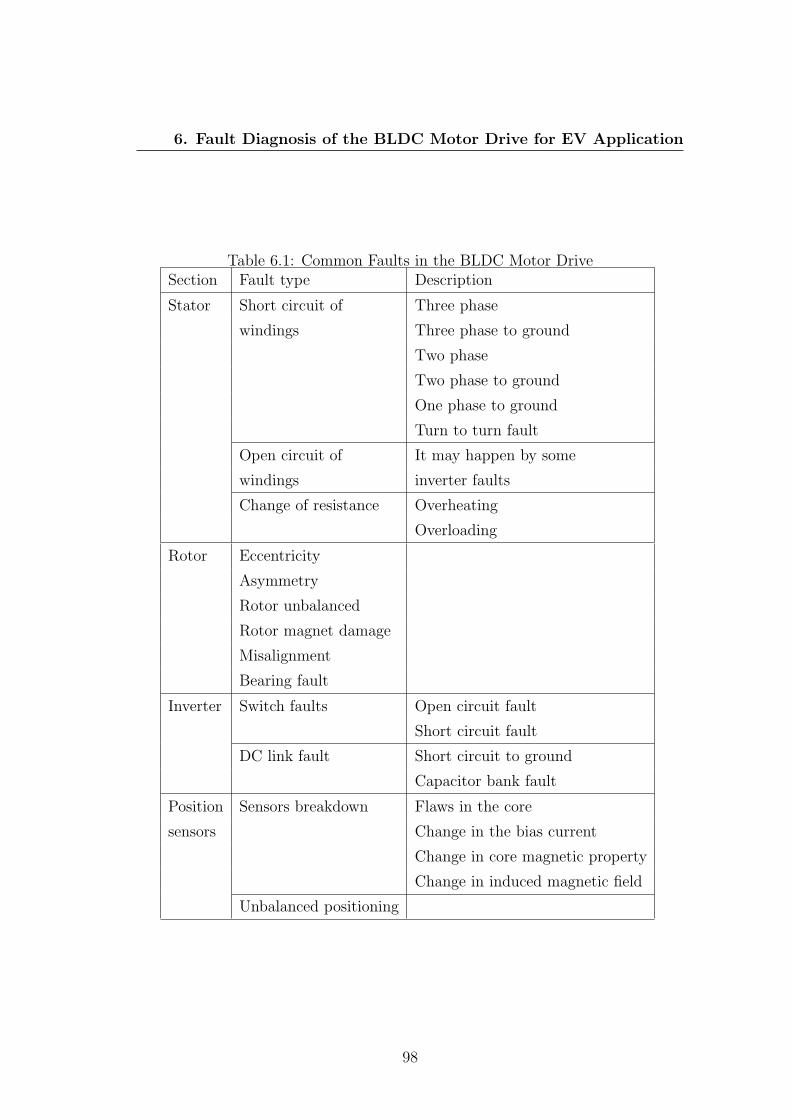
6. Fault Diagnosis of the BLDC Motor Drive for EV Application
Table 6.1: Common Faults in the BLDC Motor DriveSection Fault type Description
Stator Short circuit of Three phase
windings Three phase to ground
Two phase
Two phase to ground
One phase to ground
Turn to turn fault
Open circuit of It may happen by some
windings inverter faults
Change of resistance Overheating
Overloading
Rotor Eccentricity
Asymmetry
Rotor unbalanced
Rotor magnet damage
Misalignment
Bearing fault
Inverter Switch faults Open circuit fault
Short circuit fault
DC link fault Short circuit to ground
Capacitor bank fault
Position Sensors breakdown Flaws in the core
sensors Change in the bias current
Change in core magnetic property
Change in induced magnetic field
Unbalanced positioning
98

6. Fault Diagnosis of the BLDC Motor Drive for EV Application
Fault diagnostic algorithms of the BLDC motor are classified by employing
signal analysis, model based and knowledge based methods [13]. In the signal
analysis based methods fault is detected through comparison of the extracted
features of the motor signals with the ideal signals at normal operating condition.
The main advantage of this method is that it does not need the BLDC motor
model for fault detection, however fault diagnosis is not fast compared to the
other two methods [81]. Parameter estimation techniques are normally used
to diagnose the fault in the model based techniques. Fault diagnosis in this
method is quite fast and can be used for online fault monitoring, however an
exact dynamic model of the BLDC motor is needed. Reported research works
by Liu et al. [13] and Moseler et al. [82] are good examples of a model-based
fault diagnosis system for the BLDC motors. Expert systems using fuzzy logic or
neural network are developed for fault diagnosis in the knowledge based methods
[13]. The knowledge can be gathered either through an experienced engineer with
a thorough understanding of the BLDC motor system, or via a comprehensive
study of the BLDC motor dynamics through simulation model of the motor [81].
Fault diagnosis systems presented in this chapter are knowledge based expert
systems that use signal analysis methods.
A fault tolerant control system for inverter open circuit switch faults of the
BLDC motor for EV application is discussed in the next section. Inverter short
circuit switch faults are removed by six fast acting fuses that are connected in
series with inverter switches. Therefore a short circuit fault is treated as an
open circuit fault by the proposed FTCS [79]. Dynamic parameters of a four
wheel drive EV using in-wheel BLDC motors are analysed under inverter open
switch fault of the motor. Fault diagnosis technique and remedial strategies are
discussed. A fault tolerant control system for position sensors breakdown in
the BLDC motors is also presented in the fourth section of this chapter. The
BLDC motor behaviour is analysed under various position sensor faults. Position
sensor fault diagnosis algorithm and the remedial strategy to rectify the fault
are discussed. Effectiveness of the both proposed fault diagnosis techniques are
investigated through experimental results.
99
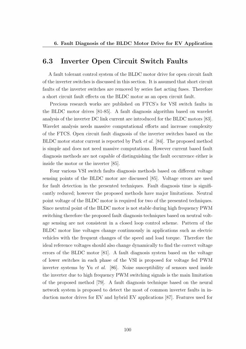
6. Fault Diagnosis of the BLDC Motor Drive for EV Application
6.3 Inverter Open Circuit Switch Faults
A fault tolerant control system of the BLDC motor drive for open circuit fault
of the inverter switches is discussed in this section. It is assumed that short circuit
faults of the inverter switches are removed by series fast acting fuses. Therefore
a short circuit fault effects on the BLDC motor as an open circuit fault.
Precious research works are published on FTCS’s for VSI switch faults in
the BLDC motor drives [81-85]. A fault diagnosis algorithm based on wavelet
analysis of the inverter DC link current are introduced for the BLDC motors [83].
Wavelet analysis needs massive computational efforts and increase complexity
of the FTCS. Open circuit fault diagnosis of the inverter switches based on the
BLDC motor stator current is reported by Park et al. [84]. The proposed method
is simple and does not need massive computations. However current based fault
diagnosis methods are not capable of distinguishing the fault occurrence either is
inside the motor or the inverter [85].
Four various VSI switch faults diagnosis methods based on different voltage
sensing points of the BLDC motor are discussed [85]. Voltage errors are used
for fault detection in the presented techniques. Fault diagnosis time is signifi-
cantly reduced; however the proposed methods have major limitations. Neutral
point voltage of the BLDC motor is required for two of the presented techniques.
Since neutral point of the BLDC motor is not stable during high frequency PWM
switching therefore the proposed fault diagnosis techniques based on neutral volt-
age sensing are not consistent in a closed loop control scheme. Pattern of the
BLDC motor line voltages change continuously in applications such as electric
vehicles with the frequent changes of the speed and load torque. Therefore the
ideal reference voltages should also change dynamically to find the correct voltage
errors of the BLDC motor [81]. A fault diagnosis system based on the voltage
of lower switches in each phase of the VSI is proposed for voltage fed PWM
inverter systems by Yu et al. [86]. Noise susceptibility of sensors used inside
the inverter due to high frequency PWM switching signals is the main limitation
of the proposed method [79]. A fault diagnosis technique based on the neural
network system is proposed to detect the most of common inverter faults in in-
duction motor drives for EV and hybrid EV applications [87]. Features used for
100

6. Fault Diagnosis of the BLDC Motor Drive for EV Application
fault detection in neural network are extracted from torque, voltage and current
signals of the induction motor. The proposed fault diagnosis technique is fast and
accurate. Complex algorithm, high number of used sensors and need of sensing
the neutral voltage point of the BLDC motor are main drawbacks of the proposed
method [81].
Effect of the inverter switch faults on dynamic parameters of a four in-wheel
drive EV are analysed in this section. A knowledge based fault diagnosis tech-
nique is proposed to detect and identify the inverter open circuit fault in the
following. The proposed fault diagnosis algorithm is validated through experi-
mental data. Some of the presented simulation and experimental results in this
section have been published by Tashakori et al. [79][81].
6.3.1 EV Dynamics Analysis under Inverter Open Circuit
Switch Fault
Simulation models are mainly developed to decrease the cost and length of
the design process of advanced systems. They can be used to study behaviour of
the systems under abnormal condition. Modelling of the hybrid electric vehicles
has been grown since 1970s [88]. Simulation models are used to study various
aspects of the vehicle; for instance vibration, vehicle handling, noise, vehicle
performance, safety, stability, component testing and etc. [89]. However there are
few simulation models of pure electric vehicle to study effect of the in-wheel motor
faults on the EV performance. A four in-wheel drive EV using four BLDC motors
is modelled in Simulink using Simscape library to analyse the EV performance
during inverter open circuit switch faults in the in-wheel motors. Schematic
diagram of the four in-wheel drive EV model is shown in Figure 6.3 [79].
Four BLDC motors using digital PWM speed controllers are modelled as drive
train of the EV. Specifications of the BLDC motor model BLK423S manufactured
by Anaheim Automation Company are used in the EV model (refer to Table 3.2
on the page 43). The duty cycle PWM control signal is applied to all six switches
of the VSI. A vehicle body in longitudinal motion from SimDriveline library is
used as vehicle body model. Specifications of the vehicle’s body used in the EV
model are given in Table 6.2.
101

6. Fault Diagnosis of the BLDC Motor Drive for EV Application
Figure 6.3: Schematic diagram of the four in-wheel drive EV model
Table 6.2: Specification of the Vehicle’s Body Used in the EV Model
Description Value Unit
Mass 1200 Kg
Number of in-wheel motors 4 -
Horizontal distance from 1.4 m
CG to front wheels
Horizontal distance from 1.6 m
CG to rear wheels
CG height above ground 0.5 m
Frontal area 3 m2
102

6. Fault Diagnosis of the BLDC Motor Drive for EV Application
6.3.1.1 No Fault Condition
The electric vehicle model is tested to run from stall position up to 2000 RPM
reference speed of the in-wheel BLDC motors on a flat road (zero inclination)
under no fault condition. Speed response of the electric vehicle is shown in Km/h
in Figure 6.4 [79]. Speed of the vehicle is increased gradually up to 113 Km/h in
50 seconds after start moving.
Figure 6.4: EV speed under no fault condition
Normal forces applied to the tires from the electric vehicle’s body are shown
in Figure 6.5 [79]. As can be seen in the figure, force on tires changes fast during
the first few seconds when the EV has the highest acceleration rate. The force
on the rear tires are more than the front tires at starting time that is due to
central gravity (CG) position of the vehicle’s body. As the vehicle approaches to
the constant speed region, tire forces are almost constant but forces on the front
tires are more than those on the rear tires.
103

6. Fault Diagnosis of the BLDC Motor Drive for EV Application
Figure 6.5: Normal tire forces under no fault condition
In-wheel BLDC motors start from stall position up to 2000 RPM reference
speed of digital PWM controllers. Speed responses of the in-wheel BLDC motors
are shown in Figure 6.6 [79]. As can be seen the in-wheel electric motors operate at
the same speed to keep the EV moving stable in a straight line. Speed fluctuation
of the front wheels at starting point is due to the slip of front tires.
Electric torques produced by in-wheel motors are shown in Figure 6.7 [79]. As
can be seen the in-wheel motors deliver the same electric torques to the wheels
that keep the electric vehicle moving stable. Effect of the front tires slip can also
be seen in the produced torques of the in-wheel BLDC motors A and B. In-wheel
motors are produced the initial torque of 350 N.m to overcome the high inertia
of the vehicle’s body at stall position. Produced electric toques by the in-wheel
motors are reduced to 30 N.m as the speed of the vehicle reaches to 113 km/h.
104

6. Fault Diagnosis of the BLDC Motor Drive for EV Application
Figure 6.6: Speed responses of the BLDC motors under no fault condition
Figure 6.7: Torque responses of the BLDC motors under no fault condition
105

6. Fault Diagnosis of the BLDC Motor Drive for EV Application
6.3.1.2 VSI Open Circuit Fault
The electric vehicle model is run from stall position up to 2000 RPM refer-
ence speed of the in-wheel BLDC motors. Open circuit fault switch S1 (refer to
Figure 6.1) of the inverter is applied to the in-wheel BLDC motor A at t = 40 s
while the EV speed is reached to 110 km/h. Other three in-wheel motors were
operating under no fault condition. No fault protection system is implemented
to the in-wheel BLDC motor drive to see the maximum fault effect on the EV
performance. Speed characteristic of the electric vehicle under open circuit fault
of switch S1 is shown in Figure 6.8 [79]. As can be seen in the figure speed of the
EV is suddenly decreased and the vehicle is unstable after fault occurrence.
Figure 6.8: EV speed under open circuit fault of switch S1
Normal forces applied to the tires from the electric vehicle body under open
circuit fault of the inverter switch S1 in the BLDC motor A are shown in Figure 6.9
[79]. Applied Vertical forces to the tires oscillate with high amplitude ripples after
the fault occurrence that is due to the unbalanced load torques on the wheels in
post-fault condition.
106

6. Fault Diagnosis of the BLDC Motor Drive for EV Application
Figure 6.9: Normal tire forces under open circuit fault of switch S1
Speed and torque responses of the in-wheel BLDC motors under open circuit
fault of the inverter switch S1 in the BLDC motor A are shown in Figure 6.10 and
Figure 6.11 respectively [79]. High amplitude notches can be seen in speed and
torque responses of the faulty in-wheel motor (the BLDC motor A). The faulty
in-wheel motor is totally unstable and speed and torque responses of other three
in-wheel BLDC motors are also deteriorated after fault. Other three motors are
effected due to unbalanced distribution of the vehicle force on tires, load torques
on the motors, after fault occurrence (refer to the Figure 6.9).
The four wheel drive EV model is also tested for inverter open circuit fault
of switch S2 of the BLDC motor A. Simulation results (refer to the Appendix A)
show unstable performance of the EV and almost are same as the inverter open
circuit fault of switch S1. Therefore performance of the electric vehicle is not safe
under inverter open circuit faults. Sudden VSI switch fault occurrence put life
of the passengers at risk and makes the electric vehicle a hazard to other nearby
vehicles or people on the road.
107

6. Fault Diagnosis of the BLDC Motor Drive for EV Application
Figure 6.10: Torque responses of the BLDC motors under open circuit fault ofswitch S1
Figure 6.11: Speed responses of the BLDC motors under open circuit fault ofswitch S1
108

6. Fault Diagnosis of the BLDC Motor Drive for EV Application
Comparison of the EV performance under faulty condition with no fault con-
dition demonstrates the need of FTCS’s for the in-wheel motors to improve safety
of the electric vehicles.
6.3.2 Fault Diagnosis
In this section fault detection and identification algorithms of the inverter open
circuit switch faults of the three phase BLDC motors are presented. Any switch
fault of the VSI effects directly on the applied voltages to the BLDC motor.
Therefore pattern change of the BLDC motor line voltages are used for fault
diagnosis. Line voltages of the BLDC motor are measured with respect to the
negative terminal of the VSI DC link.
6.3.2.1 Fault Detection
Any pattern change of the line voltages of the BLDC motor for constant speed
and torque load condition is the signature of fault occurrence. Variations of the
motor speed and load torque should be considered in fault diagnosis. Discrete
Fourier transform analysis is used to detect pattern changes of the BLDC motor
line voltages. Frequency spectrum of the measured voltages are extracted from
equation (6.1) for the specific intervals of time. Power Spectral Density (PSD)
of the calculated frequency spectrum of the measured voltages of each phase
of the BLDC motor are calculated from equation (6.2) for each time interval.
Successive PSD values are compared to find the PSD errors of each phase from
equation (6.3).
V (f) =N−1∑n=0
Vne−j2πk n
N k = 0, 1, ..., N (6.1)
Em(f) = |V (f)|2 (6.2)
εm = Em(f)− Em−1(f) (6.3)
In practice, line voltages of the BLDC motor are sensed for specific intervals
109

6. Fault Diagnosis of the BLDC Motor Drive for EV Application
of time continuously while the motor is operating in constant speed and torque
load condition. The minimum time interval for correct fault detection is one
electrical rotation of the BLDC motor. The time of one electrical degree rotation
is inversely proportional to the BLDC motor speed. Fault occurrence is detected
if calculated PSD errors of the BLDC motor line voltages exceeds the predefined
limits. Five percent of the calculated PSD value of the BLDC motor line voltages
under no fault condition are set as the limit to avoid short term disturbance
detections.
6.3.2.2 Fault Identification
An expert system is developed to identify the faulty switch of inverter based on
studying the BLDC motor performance under faulty condition through the sim-
ulation model. The BLDC motor model is validated through the experimental
set-up. A three phase low voltage BLDC motor is used as an experimental test
motor. A Low voltage (LV) development board of microchip using PIC18F4231
micro-controller is programmed to control the experimental BLDC motor. Ex-
perimental test rig of the BLDC motor and specifications of the experimental test
motor used in simulation model are given in Chapter 4 (refer to Figure 4.8 and
Table 4.3).
Digital PWM controller is implemented to control speed of the BLDC motor.
An embedded code is written in Simulink model to produce a duty cycle controlled
PWM signal. High frequency PWM signal is applied to all switches of the inverter.
The experimental test BLDC motor and its simulation model are tested at 2000
RPM under 0.1 N.m load torque. Line voltage and Hall Effect signal of phase A of
the experimental set-up and the simulation model of the BLDC motor are shown
in Figure 6.12 [12]. Agreements between simulation and experimental results
validate the BLDC motor model. The validated BLDC motor model is also used
to develop fault diagnosis system for Hall Effect sensors failure in Section Five.
Inverter open circuit switch faults are applied to the validated BLDC motor
model and results are analysed to develop the fault diagnosis system. Power spec-
tral density errors of the line voltages of the BLDC motor model are calculated
under healthy operating condition and after fault occurrence. A knowledge based
110

6. Fault Diagnosis of the BLDC Motor Drive for EV Application
Figure 6.12: Line voltage and Hall Effect signal of phase A of BLDC motor
table is developed to identify the fault by analysing the calculated PSD errors of
the motor line voltages in various fault conditions.
Open Circuit Fault of Switch S1 is applied at t = 0.5 to the BLDC
motor model. Line voltages of the BLDC motor during the open circuit fault of
switch S1 are shown in Figure 6.13 [79]. Positive amplitude spikes can be seen
in line voltage of the faulty phase of the motor. The line voltage of phase A has
totally distorted after the fault occurrence. Line voltages of phase B and phase C
111

6. Fault Diagnosis of the BLDC Motor Drive for EV Application
are also changed, though the voltage of phase A has the most variations. There-
fore the PSD error of the phase A voltage should be the maximum. Calculated
Power spectral density errors of the BLDC motor line voltages for open circuit
fault of switch S1 are given in Table 6.3 [79].
Figure 6.13: Line voltages of BLDC motor during open circuit fault of switch S1
Table 6.3: Simulation PSD Values for Open Circuit of S1
Description Phase A Phase B Phase C
PSD before fault [Em−1(f)] 963.95 958.56 954.67
PSD after fault [Em(f)] 1.0862e+05 1019.76 932.06
PSD error [εm] 107656.05 61.2 -22.61
Open Circuit Fault of Switch S2 is applied at t = 0.5 to the BLDC
motor model. Line voltages of the BLDC motor during the open circuit fault
of switch S2 are shown in Figure 6.13 [79]. As can be seen the line voltage of
112

6. Fault Diagnosis of the BLDC Motor Drive for EV Application
phase A, the faulty phase, has negative amplitude spikes. Voltage of phase B
and C are also significantly distorted, however variations of the phase A voltage
is much more than other two phases. Calculated power spectral density errors
of the BLDC motor line voltages for open circuit fault of switch S2 are given in
Table 6.4 [79].
Figure 6.14: Line voltages of BLDC motor during open circuit fault of switch S2
Table 6.4: Simulation PSD Values for Open Circuit of S2
Description Phase A Phase B Phase C
PSD before fault [Em−1(f)] 963.95 958.56 954.67
PSD after fault [Em(f)] 1.0912e+05 1076 1115.5
PSD error [εm] 108156.05 117.44 160.83
Line voltages of the BLDC motor are also studied under open circuit faults of
other inverter switches through the validated simulation model. The calculated
113

6. Fault Diagnosis of the BLDC Motor Drive for EV Application
PSD errors for open circuit faults of phase A switches of the inverter can be
generalized for the other two phases due to symmetry of the BLDC motor [12].
Two flags are defined for fault diagnosis; Switch Fault Flag (SFF) for each phase
of the motor to identify the faulty switch and Fault Phase Flag (FPF) to identify
the faulty phase. Numeric values are assigned to SFF of each phase and FPF
according to the linguistic variables based on the calculated PSD errors as below
[79],
• SFF is ‘-1’ if PSD error is over the limits and negative;
• SFF is ‘0’ if PSD error is in the limits;
• SFF is ‘1’ if PSD error is over the limits and positive;
• FPF is ‘0’ if no fault is detected;
• FPF is ‘1’ if maximum PSD error related to phase A;
• FPF is ‘2’ if maximum PSD error related to phase B;
• FPF is ‘3’ if maximum PSD error related to phase C.
A multidimensional knowledge based table are developed to identify the faulty
switch based on simple quasi-fuzzy if-then rules according to the assigned numeric
values of the flags. Developed knowledge based if-then rules for inverter switches
faults diagnosis are shown in Table 6.5 [79].
Table 6.5: Proposed Knowledge Based Table for Inverter Switches Faults Diag-nosis
Fault type SFF SFF SFF FPF
phase A phase B phase C
No fault 0 0 0 0
Open circuit S1 1 1 0 1
Open circuit S2 1 1 1 1
Open circuit S3 0 1 1 2
Open circuit S4 1 1 1 2
Open circuit S5 1 0 1 3
Open circuit S6 1 1 1 3
114

6. Fault Diagnosis of the BLDC Motor Drive for EV Application
As the fault diagnosis is based on the PSD errors of line voltages, there is no
need to know the exact patterns of the BLDC motor line voltages in advance.
This is the most advantage of the proposed fault diagnosis system compared to
the previously reported systems for the EV application.
6.3.3 Experimental Results
The low voltage development board of the microchip is modified to test the
open circuit fault of the inverter switches and Hall Effect sensors. The modified
control board of the BLDC motor is shown in Figure 6.15 [79]. There is an in-built
over current protection circuit in the control board that avoids phase currents to
exceed a predefined limit.
Figure 6.15: The modified LV development board control drive of BLDC motor
Open circuit faults of phase A switches of the VSI is applied to the BLDC
motor while it is running at 2000 RPM under 0.1 N.m load torque. Line voltages
of the motor under open circuit faults of switches S1 and S2 are shown in Fig-
ure 6.16 and Figure 6.17 respectively [79]. As can be seen the voltage of faulty
phase, phase A, is totally deteriorated for both open circuit faults of switches of
115
6. Fault Diagnosis of the BLDC Motor Drive for EV Application
S1 and S2. Voltages of phase B and phase C are also distorted, though the phase
A voltage has always the most variations same as the simulation results.
Figure 6.16: Line voltages of BLDC motor under open circuit fault of switch S1
116

6. Fault Diagnosis of the BLDC Motor Drive for EV Application
Figure 6.17: Line voltages of BLDC motor under open circuit fault of switch S2
117

6. Fault Diagnosis of the BLDC Motor Drive for EV Application
Power spectral density errors of the BLDC motor line voltages for experi-
mental open circuit faults of switches S1 and S2 are given in Tables 6.6 and 6.7
respectively. AS can be seen PSD errors of the line voltage of phase A is maxi-
mum for both open circuit faults of switches of S1 and S2 compared to the other
two phases. However the PSD errors of experimental results are not as large as
the PSD errors of simulation results due to the effect of over current protection
circuit of the control drive.
Table 6.6: Experimental PSD Values for Open Circuit of S1
Description Phase A Phase B Phase C
PSD before fault [Em−1(f)] 314.98 322.17 322.35
PSD after fault [Em(f)] 348.34 339.26 319.36
PSD error [εm] 33.36 17.09 -2.99
Table 6.7: Experimental PSD Values for Open Circuit of S2
Description Phase A Phase B Phase C
PSD before fault [Em−1(f)] 314.98 322.17 322.35
PSD after fault [Em(f)] 352.97 344.32 340.12
PSD error [εm] 37.99 22.15 17.77
The experimental BLDC motor drive is also tested under open circuit switch
faults of other legs of the inverter. Experimental results are similar to the open
circuit switch faults of leg A of inverter. The most pattern changes always belong
to the line voltage of faulty phase. Discussed experimental results validate the
fault diagnosis algorithm developed by simulation results for inverter switches
open circuit faults.
118

6. Fault Diagnosis of the BLDC Motor Drive for EV Application
6.3.4 Remedial Strategy
EV drive train faults must be isolated and rectified in a mean time to main-
tain the maximum possible vehicle performance and safety of the passengers.
Therefore after the faulty switch is identified, the corresponding faulty leg is dis-
connected from the inverter by implemented controlled switches in each leg of the
VSI.
There are various inverter reconfiguration topologies to maintain the BLDC
motor operation in post-fault condition. Inverter topologies are not in the scope
of this chapter; however two simple inverter topologies are discussed for post-
fault condition with respect to the electric vehicle application. Reconfiguration
of the three phase voltage source inverter to the four switches topology inverter
for the BLDC motors in post-fault condition is recommended by Lee et al. [90].
Schematic diagram of the proposed four switches topology inverter is shown in
Figure 6.18 [81].
Figure 6.18: Schematic diagram of the proposed four switches topology inverter
After isolating the faulty leg of the inverter, the corresponding phase of the
BLDC motor is connected to the midpoint of DC link of the VSI through con-
trol switches Sa; Sb; Sc. Reconfiguring to the four switch mode operation of the
119

6. Fault Diagnosis of the BLDC Motor Drive for EV Application
inverter avoids further major faults inside the in-wheel BLDC motor drive. How-
ever performance of the in-wheel BLDC motor is degraded. This method can be
used to increase the reliability of the in-wheel BLDC motors just for a short time
in post-fault condition until the vehicle gets the proper service [81].
A modular and easy controlled fault tolerant VSI using a redundant leg is
proposed for the BLDC motor drives by Errabelli et al. [91]. The faulty leg of
the inverter is replaced by the redundant leg in post-fault condition. Schematic
diagram of the proposed fault tolerant inverter of the BLDC motor with a re-
dundant leg is shown in Figure 6.19 [81]. The corresponding faulty phase of the
BLDC motor is connected to the redundant leg of the inverter through indepen-
dent control switches Sra; Srb; Src. In this technique performance of the in-wheel
BLDC motor is not degraded compared to the four switches topology inverter;
however its manufacturing cost is due to the redundant leg. Since the reliability
and safety of the in-wheel motor drive is more important than the cost in EV
application, therefore the proposed fault tolerant VSI with a redundant leg is
recommended for in-wheel motors.
Figure 6.19: Schematic diagram of the proposed fault tolerant inverter with aredundant leg
120

6. Fault Diagnosis of the BLDC Motor Drive for EV Application
6.4 Position Detection Sensors Failure
In this section a fault tolerant control system for position sensors failure of
a three phase BLDC motor are discussed. Commutation of the BLDC motor is
done with respect to the position sensor signals. Therefore failure or malfunction
of the position sensors effects directly on the motor performance. On the other
hand faults in position sensor may result in immediate over current of the BLDC
motor drive under high load torques [92]. Unbalanced positioning of the Hall
Effect sensors by manufacturer is not in the sensor failure categories and scope
of this study. However it increases low-frequency harmonics in the torque ripples
and degrades performance of the BLDC motor [93]. The main faults that may
result in failure of a Hall Effect sensor in BLDC motors are [94]:
1. Flaws in the sensor’s core due to corrosion, cracks, residual magnetic fields
and core breakage;
2. Effect of temperature variations on the magnetic properties of the ferrite
core;
3. Effect of mechanical shocks on the orientation of the induced magnetic field
in the sensor;
4. Changes in the bias current of the sensor.
There are few reported research works on fault tolerant control system of
position sensors failure in the BLDC motors. Major sensor faults of an Interior
Permanent Magnet Motor (IPMM) as the propulsion system of an electric vehicle
are discussed [92]. Position sensor faults are detected through difference between
the calculated rotor angle and the actual rotor angle. Permanent magnet rotor
position angle is calculated by a sensorless algorithm based on extended EMF in
rotating reference frame [95]. Sensorless mode control of the permanent magnet
motor is recommended as a remedial strategy. Complexity of the BLDC motor
sensorless control drives and transition algorithms to the sensorless mode are the
main drawbacks of the proposed method [12]. Performance of the BLDC motor
is analysed under Hall Effect sensors faults for lunar rover wheel application
[96]. Effects of the position sensor faults on inverter switching signals and phase
currents are shown only through a simulation model; however simulation results
121

6. Fault Diagnosis of the BLDC Motor Drive for EV Application
are not discussed. There is also no discussion on fault diagnosis techniques and
remedial strategies to rectify the fault in the paper [80].
Fault diagnosis technique and a novel remedial strategy for Hall Effect sensor
failure in the BLDC motors is discussed in this section. Performance of the BLDC
motor under position sensors fault are analysed through a validated simulation
model. A knowledge based fault diagnosis technique is developed to detect the
faulty position sensor based on simulation results analysis. Finally effectiveness
of the proposed fault diagnosis algorithm is proved through experimental data.
Some of the presented simulation and experimental results in this section have
been published by Tashakori et al. [12][80].
6.4.1 Performance of the BLDC Motor under Position
Sensor Faults
Behaviour of the BLDC motor drive under various position sensor faults are
studied through a validated simulation model (refer to Figure 6.12 on the page 111)
to develop the fault diagnosis algorithm. The BLDC motor experimental set-up
is the same as the one that is used and explained for inverter switch faults in the
previous section.
Position sensor faults are applied to the validated simulation model of the
BLDC motor while the motor is running under stable and healthy condition.
Then output characteristics of the motor such as line voltages, phase currents,
speed and torque characteristics are analysed. Hall Effect sensor failure is divided
into two categories based on the output signal of the sensors. Output signal of
the sensor is constant high (logic ‘1’, Ha = 1), sensor is short circuit to it power
supply, or it is constant low (logic ‘0’, Ha = 0), sensor is open circuit [12].
Behaviour of the BLDC motor is discussed under both fault conditions of the
corresponding Hall Effect position sensor of phase A.
6.4.1.1 Hall Effect Signal is Constant Zero
Hall Effect sensor fault Ha = 0 is applied to the validated BLDC motor model
at t = 0.5 s while the motor is ruining at 2000 RPM under 0.1 N.m load torque.
Speed and torque responses of the BLDC motor under Ha = 0 fault condition are
122

6. Fault Diagnosis of the BLDC Motor Drive for EV Application
shown in Figure 6.20 [12]. As can be seen in the figure, speed and torque of the
BLDC motor is unstable and out of the control under Ha = 0 fault condition.
Figure 6.20: Speed and torque responses of BLDC motor under Ha = 0 faultcondition
Line voltages of the BLDC motor under Ha = 0 fault condition are shown in
Figure 6.21 [12]. Line voltages of the BLDC motor are measured with respect
to the negative terminal of DC link of VSI. As shown in figure line voltages of
all phases are changed due to the direct effect of Hall Effect sensor faults on the
switching signal of the inverter. Hall Effect sensor faults also increase the BLDC
motor torque ripples and degrade its performance.
Effect of the various position sensor faults on the switching signals of the
VSI are summarized in Table 6.8 [80]. Each position sensor fault changes two
switching signals of the inverter to constant zero. This effect can be considered as
an open circuit fault of two inverter switches at the same time [80]. As given in
Table 6.8 switching signals of the switches S1 and S6 are constant zero (switches
S1 and S6 are open circuit) under Ha = 0 fault condition.
123

6. Fault Diagnosis of the BLDC Motor Drive for EV Application
Figure 6.21: Line voltages of BLDC motor under Ha = 0 fault condition
6.4.1.2 Hall Effect Signal is Constant One
Hall Effect sensor fault Ha = 1 is applied to the validated BLDC motor model
at t = 0.5 s while the motor is ruining at 2000 RPM under 0.1 N.m load torque.
Speed and torque responses of the BLDC motor under Ha = 1 fault condition
are exactly similar to the Ha = 0 fault condition. Torque ripples of the BLDC
motor is increased and the motor is not stable after fault occurrence. However
switching signals of the switches S2 and S5 remain open circuit after Ha = 1 fault
occurrence that is not the same as Ha = 0 fault condition. Therefore line voltages
of the BLDC motor should be different in Ha = 1 fault condition compared to
Ha = 0 fault condition. Line voltages of the BLDC motor under Ha = 1 fault
condition are shown in Figure 6.21 [12].
124

6. Fault Diagnosis of the BLDC Motor Drive for EV Application
Table 6.8: Effect of the Various Sensor Faults on the Switching Signals of the VSI
Fault type Effected switches of VSI Switches status
Ha = 0 S1 , S6 Open
Ha = 1 S5 , S2 Open
Hb = 0 S3 , S2 Open
Hb = 1 S1 , S4 Open
Hc = 0 S5 , S4 Open
Hc = 1 S3 , S6 Open
6.4.2 Fault Diagnosis
Correct space voltage vectors are chosen according to the electrical position
of the permanent magnet rotor by decoding the commutation signals (refer to
Table 3.1). As can be seen there is no electrical position of the rotor that all
sensor signals are one or zero. Therefore addition of the commutation signals,
Hf , are either one or two under healthy operating condition of the BLDC motor.
Hf = Ha +Hb +Hc (6.4)
Hall Effect sensor faults change the value of Hf during one electrical rotation
of the rotor. If Hf = 3, it shows that one of the position sensor signals is constant
one and if Hf = 0, it means that one of the position sensor signals is constant
zero. The minimum required time for fault detection is time of one electrical
rotation of the rotor that is quite fast. Hall Effect sensors Fault detection Flag
(HFF) is introduced to detect the fault occurrence as below [80],
• HFF is set ‘0’ if Hf = 1 or Hf = 2;
• HFF is set ‘1’ if Hf = 3;
• HFF is set ‘-1’ if Hf = 0.
Position sensors faults are detected if the Fault Detection Flag is not zero.
Detection of the fault and fault type are possible through HFF; however faulty
sensor cannot be identified through fault detection flag. DFT analysis of the
line voltages of the BLDC motor is used to identify the faulty sensor. Same as
125
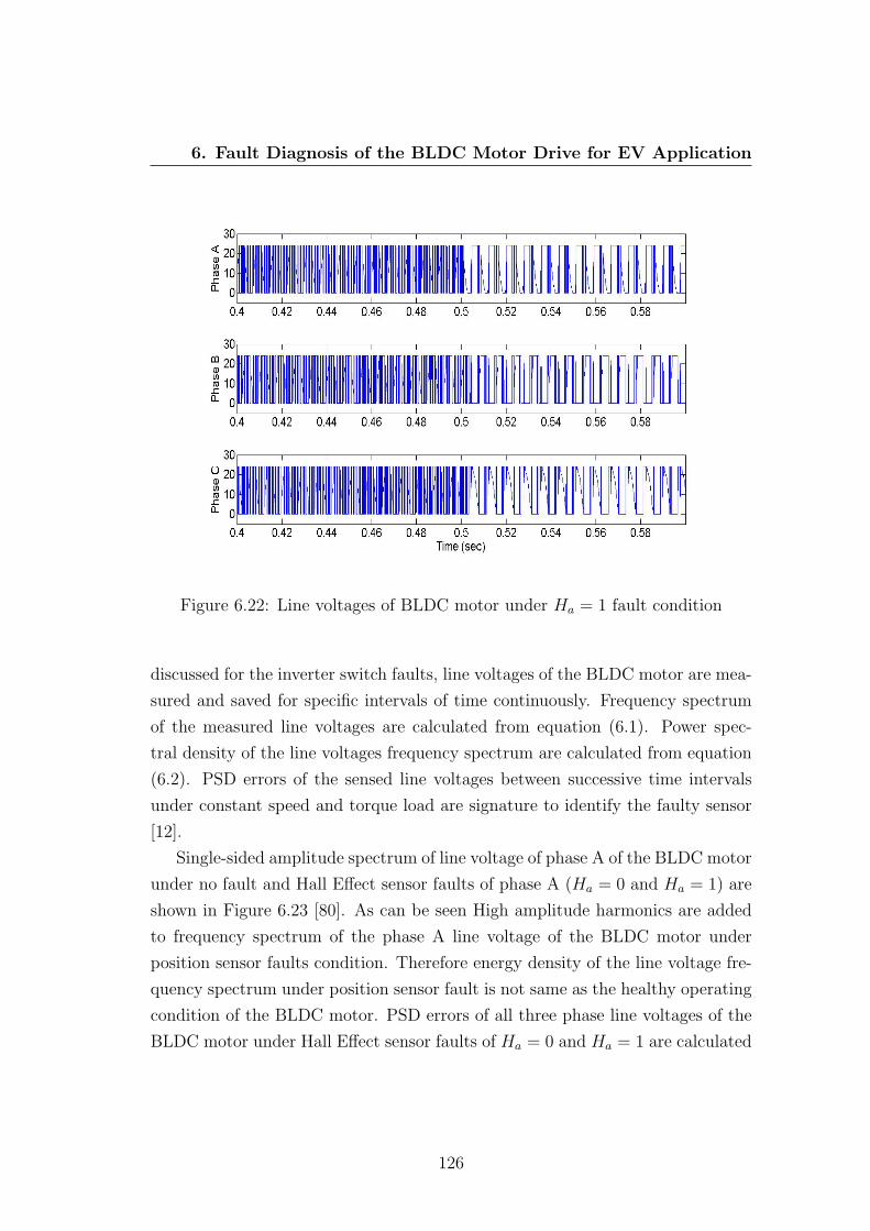
6. Fault Diagnosis of the BLDC Motor Drive for EV Application
Figure 6.22: Line voltages of BLDC motor under Ha = 1 fault condition
discussed for the inverter switch faults, line voltages of the BLDC motor are mea-
sured and saved for specific intervals of time continuously. Frequency spectrum
of the measured line voltages are calculated from equation (6.1). Power spec-
tral density of the line voltages frequency spectrum are calculated from equation
(6.2). PSD errors of the sensed line voltages between successive time intervals
under constant speed and torque load are signature to identify the faulty sensor
[12].
Single-sided amplitude spectrum of line voltage of phase A of the BLDC motor
under no fault and Hall Effect sensor faults of phase A (Ha = 0 and Ha = 1) are
shown in Figure 6.23 [80]. As can be seen High amplitude harmonics are added
to frequency spectrum of the phase A line voltage of the BLDC motor under
position sensor faults condition. Therefore energy density of the line voltage fre-
quency spectrum under position sensor fault is not same as the healthy operating
condition of the BLDC motor. PSD errors of all three phase line voltages of the
BLDC motor under Hall Effect sensor faults of Ha = 0 and Ha = 1 are calculated
126

6. Fault Diagnosis of the BLDC Motor Drive for EV Application
and given in Tables 6.9 and 6.10 respectively [80].
Figure 6.23: Amplitude spectrum of the phase A line voltage of BLDC motor
Table 6.9: PSD Values for Ha = 0 Fault ConditionDescription Phase A Phase B Phase C
PSD before fault [Em−1(f)] 957 942 938
PSD after fault [Em(f)] 807 1044 1083
PSD error [εm] -150 102 145
Table 6.10: PSD Values for Ha = 1 Fault ConditionDescription Phase A Phase B Phase C
PSD before fault [Em−1(f)] 957 942 938
PSD after fault [Em(f)] 1109 925 802
PSD error [εm] 152 -17 -135
127

6. Fault Diagnosis of the BLDC Motor Drive for EV Application
Hall Effect sensors fault Identification Flag (HIF) is introduced for each phase
of the BLDC motor. Numeric values are assigned to the fault identification flag
of each phase based on the sign of the calculated PSD errors. FIF numeric values
are assigned as below [80],
• HIF is set ‘-1’ if PSD error is negative;
• HIF is set ‘1’ if PSD error is positive.
A multidimensional table is developed to diagnose the position sensor faults of
the BLDC motor based on fault detection and identification flags. Fault diagnosis
algorithm is developed based on the gathered knowledge from characteristics of
the BLDC motor model under various Hall Effect sensor faults. Simplicity and no
need of knowing the exact pattern of the BLDC motor line voltages for different
speed and torque loads are the main advantages of the proposed fault diagnosis
method. The proposed multidimensional knowledge based table for Hall Effect
sensors fault diagnosis in the BLDC motors is shown in Table 6.11 [12].
Table 6.11: Proposed Knowledge Based Table for Position Sensor Faults Diagnosis
Fault type HIF HIF HIF HFF
phase A phase B phase C
No fault X X X 0
Ha = 0 -1 1 1 -1
Ha = 1 1 -1 -1 1
Hb = 0 1 -1 1 -1
Hb = 1 -1 1 -1 1
Hc = 0 1 1 -1 -1
Hc = 1 -1 -1 1 1
Hall Effect sensor fault occurrence and fault type are detected through the
fault detection flag, when HFF is not zero, and faulty sensor is identified based
on the fault identification flag of each phase of the BLDC motor according to the
Table 6.11.
128

6. Fault Diagnosis of the BLDC Motor Drive for EV Application
6.4.3 Experimental Results
Correctness of the proposed fault diagnosis system for Hall Effect sensors fail-
ure of the BLDC motor is investigated through experiment. Low voltage devel-
opment board of microchip has been modified to test Hall Effect sensors faults of
the experimental BLDC motor. Three half-bridge gate drivers using MOSFETs
as shown in Figure 6.24 are used as the VSI drive of BLDC motor [97]. Signal
PWM0 is applied switching signal of the switch Q0 that is equivalent of the switch
S1 in Figure 6.1.
Figure 6.24: Half-bridge gate driver and inverter of LV development board
Open circuit, Ha = 0, and short circuit, Ha = 1, faults of the corresponding
Hall Effect sensors of phase A are applied to the experimental BLDC motor while
it is running at 2000 RPM under 0.1 N.m torque load. Speed oscillations and
high acoustic noise are the first observations in the BLDC motor drive after fault
occurrence. Six LED lights are provided on the control board that are on when
the corresponding switching signals are logic high. Status of the LED lights
for open circuit and short circuit faults the corresponding Hall Effect sensors of
phase A are shown in Figure 6.25 [80]. Equivalent switching signals of S1 and S6
(PWM1 and PWM4) of VSI drive of the experimental BLDC motor are constant
129

6. Fault Diagnosis of the BLDC Motor Drive for EV Application
zero for Ha = 0 fault. Equivalent switching signals of S5 and S2 (PWM5 and
PWM0) of inverter are also constant zero for Ha = 1 fault.
Figure 6.25: Corresponding switching LED lights on the control board underposition sensor faults of phase A: (a) Open circuit fault (b) Short circuit fault
Therefore simulation results presented in Table 6.8 on the page 125 are val-
idated through experimental results. Line voltages of the experimental BLDC
motor under Ha = 0 and Ha = 1 fault conditions are shown in Figure 6.26 and
Figure 6.27 respectively [80].
As is shown in the figures, line voltages of the experimental BLDC motor are
changed during faults compared to the healthy operating condition. Single-sided
amplitude spectrum of the experimental BLDC motor line voltage of phase A
under no fault and Hall Effect sensor faults of phase A are shown in Figure 3.3
[80]. High amplitude harmonics can be seen on the phase A line voltage of
the experimental BLDC motor under position sensor fault conditions. However
amplitude and frequency of the added harmonics are different for Ha = 0 fault
compared to Ha = 1 fault. Therefore power spectral density of the line voltages
are different according the fault types in post-fault condition.
130

6. Fault Diagnosis of the BLDC Motor Drive for EV Application
Figure 6.26: Line voltages of the experimental BLDC motor under Ha = 0 fault
131

6. Fault Diagnosis of the BLDC Motor Drive for EV Application
Figure 6.27: Line voltages of the experimental BLDC motor under Ha = 1 fault
132

6. Fault Diagnosis of the BLDC Motor Drive for EV Application
Figure 6.28: Amplitude spectrum of the phase A line voltage of experimentalBLDC motor
Power spectral density (PSD) errors of the experimental BLDC motor line
voltages under Ha = 0 and Ha = 1 fault conditions are calculated and given
in Table 6.12 and Table 6.13. Calculated PSD errors of the experimental line
voltages under Hall Effect sensor fault condition validate the calculated PSD
errors of the simulation line voltages. However experimental PSD errors are not
as large as simulation ones that is due to the inbuilt over current protection circuit
of the controller board.
The experimental BLDC motor is also tested under the corresponding Hall
Effect sensors faults of other phases. Calculated experimental PSD errors of the
line voltages under Hall Effect sensors faults of other two phases are similar to the
presented experimental results for phase A of the BLDC motor. Experimental
results validate the proposed knowledge based fault diagnosis table for position
133

6. Fault Diagnosis of the BLDC Motor Drive for EV Application
Table 6.12: PSD Values for Experimental Ha = 0 Fault Condition
Description Phase A Phase B Phase C
PSD before fault [Em−1(f)] 314.9870 322.1711 322.3580
PSD after fault [Em(f)] 301.1294 329.6414 369.2658
PSD error [εm] -13.8576 7.4703 46.9078
Table 6.13: PSD Values for Experimental Ha = 1 Fault Condition
Description Phase A Phase B Phase C
PSD before fault [Em−1(f)] 314.9870 322.1711 322.3580
PSD after fault [Em(f)] 330.2032 319.5225 310.2840
PSD error [εm] 15.2162 -2.6486 -12.074
sensors breakdown of the BLDC motors.
6.4.4 Remedial Strategy
The signal of the faulty Hall Effect sensor should be disconnected from the
BLDC motor drive after fault detection. Signal of the faulty sensor is generated
by the controller by implementing 120 electrical degree delay to one of the other
available Hall Effect signals. Electrical degree delays are calculated in time as
it is discussed in Chapter 5. If the BLDC motor speed does not change during
commutation intervals, the time for one full electrical rotation of the permanent
magnet rotor of the BLDC motor can be calculated from equation (6.5).
Tone electrical degree =60
P2
(360× ωref )(6.5)
where P is number of the motor poles and ωref is there reference speed of the
controller. Effectiveness of the proposed equation to calculate the correct time
of electrical delays of the BLDC motors is proved through simulation and exper-
imental results in the previous chapter [34].
An embedded Matlab code is implemented in the BLDC motor simulation
model to test performance of the proposed FTCS for Hall Effect sensors fault.
Ha = 0 fault is applied to the BLDC motor model at t = 0.5 s while the motor
134

6. Fault Diagnosis of the BLDC Motor Drive for EV Application
Figure 6.29: Speed response of the fault tolerant controlled BLDC motor drive
is running at 2000 RPM under 0.1 N.m torque load. Speed characteristics of the
fault tolerant controlled BLDC motor drive is shown in Figure 6.29 [12].
As can be seen in the figure, fault tolerant control drive of the BLDC motor
detect, identifies and maintains performance of the motor in post-fault condition.
The commutation signal of phase A is generated correctly by implementing the
calculated the time delays. Fault diagnosis time in simulation model is about
0.113 second which is fast and acceptable for the BLDC motor drives.
6.5 Conclusion
In this chapter two fault tolerant control systems are presented for inverter
switch faults and Hall Effect position sensors failure of the BLDC motor drives.
Performance of a four in-wheel drive EV are studied under open circuit faults of
inverter switches S1 and S2 in one of the front in-wheel BLDC motors through
simulation. Results show that EV becomes unstable immediately after VSI switch
faults occurrence. Behaviour of the BLDC motor is analysed under various in-
verter switches and position sensor faults through a validated simulation model.
135

6. Fault Diagnosis of the BLDC Motor Drive for EV Application
Results show that these faults effect directly on the applied voltages and cause
the BLDC motor to be unstable. Therefore necessities of implementing FTCS’s
for the in-wheel BLDC motors are inevitable to increase safety and reliability of
the electric vehicles.
The proposed fault diagnosis systems are based on the DFT analysis of the line
voltages of the BLDC motor. Knowledge based tables are developed to diagnose
the faulty switch of inverter and the faulty sensor by analysing power spectral
density errors of the BLDC motor line voltages. Since the PSD errors of the
line voltages are signature of fault detection and identification in both proposed
fault diagnosis systems; the exact pre-knowledge of the line voltages pattern for
various reference speed or torque loads is not needed.
Fault tolerant three phase VSI with a redundant leg is recommended to isolate
and rectify the inverter switch faults. A simple method is also introduced to
generate the signal of faulty position sensor by implementing the time delays
between Hall Effect signals in post fault condition. Effectiveness of the proposed
fault diagnosis algorithms and the knowledge based tables are validated through
the experiment results.
136

Chapter 7
Conclusion
Electric vehicles have been considered for the green transportation since 1980’s.
Electric motors are the main propulsion system in the electric vehicles. Different
electric motors are used as drive train of electric vehicles. Induction and BLDC
motors are the most popular drive trains used in the electric vehicles available in
the world market by the manufacturers. In-wheel motor technology has been one
of the research interests in automotive industry in the last decade. Important
technical requirements of an in-wheel motor are: high torque at low speeds; high
torque/power to size ratio; high efficiency; high dynamic response; robustness;
low noise susceptibility. Performance of the brushed DC, induction, BLDC and
switched reluctance motors are compared according to the in-wheel technology
requirements through simulation.
Simulation models of the motors are tested under the same normal and crit-
ical conditions. Simulation results show better torque/speed characteristics and
faster dynamic response of the BLDC motor compared to the other motors in
the normal condition. Brushed DC motor also has high torque at low speeds and
fast dynamic response in the normal condition. Low efficiency, low speed ranges
and periodic need of maintenance are the main disadvantages of the brushed DC
motors that are not suitable for the EV application. On the other hand, the
induction motor has better performance compared to the other motors in the
critical condition. Low efficiency at high speeds, slow dynamic response and slip
are the major drawbacks of the induction motor for the in-wheel motor applica-
tion. The switched reluctance motor has also a good performance in the critical
137

7. Conclusion
condition, however high amplitude torque ripples and noise susceptibility are its
main limitations. The BLDC motor performance is not suitable for in-wheel mo-
tor application specifically during electrical faults. Implementing fault tolerant
control systems improve reliability and robustness of the BLDC motors. Com-
parison results and discussions of the motors presented in Chapter 2 conclude to
the point that the BLDC motor is the most suitable motor for the in-wheel motor
electric vehicles.
Precise electronic control of the in-wheel motors improves safety, efficiency and
overall performance of the electric vehicles. An accurate simulation model of the
in-wheel motors are needed to study performance of the motor for different control
algorithms. Therefore a three phase star connected BLDC motor model with an
ideal back-EMF has been modelled in the Chapter 3. The presented model is
based on Laplace transform of the mathematical equations of the BLDC motor.
Simulation results of the motor model are validated through the experimental
data of a three phase in-wheel BLDC motor hub designed for electric motor cycle
application. Simplicity and the ideal back-EMF waveforms of the proposed model
make it useful for performance analysis of the various BLDC motor drives.
Mechanical output power of the electric motors is dependant on speed and
produced electric torque. Therefore, precise torque control of the in-wheel mo-
tors improves performance of the electric vehicles. Direct torque control switching
technique of the BLDC motor is discussed in Chapter 4. DTC drive of the BLDC
motor is simulated in Simulink and results are compared with those of the con-
ventional switching technique of the motor. Comparison results show effective
control of the BLDC motor torque and lower torque ripples by the DTC switch-
ing technique compared to the conventional switching technique. The proposed
DTC drive is implemented to test the experimental low voltage BLDC motor.
Experimental results show capability of the DTC drive in effective control of the
torque in various conditions.
Sensorless drives of the BLDC motor are widely used in various applications
in recent years. The novel back-EMF based sensorless drive of the BLDC motor
presented in Chapter 5, is based on back-EMF zero crossing detection of only
one phase of the BLDC motor. Commutation signal of one phase is generated
by 30 electrical degree delays from ZCD points of the back-EMF voltage. Com-
138

7. Conclusion
mutation signals of the other phases are generated based on 120 electrical degree
phase delays from the first commutation signal. Cost, sensing circuitry and noise
susceptibility of the BLDC motor sensorless drives are decreased by the proposed
method. The proposed sensorless technique of the BLDC motor is simulated,
built practically and tested experimentally. Good agreements between simula-
tion and experimental results justify the correct performance of the proposed
sensorless BLDC motor drive.
A digital PWM speed controller using a PI controller to select the duty cycle
of the PWM signal is implemented in the proposed sensorless drive of the BLDC
motor. Stability of the BLDC motor drive using digital PWM speed controller is
analysed through Lyapunov method. A novel condition is presented to calculate
the ideal duty cycle of PWM signal based on the motor parameters to keep
the BLDC motor stable at the reference speed. Correctness of the introduced
stability analysis condition is investigated through simulation and experiment.
Experimental and simulation results validate the introduced stability analysis
condition for PWM speed controller of the BLDC motor.
Fault tolerant control systems effectively improve performance of the electric
motors under fault condition. Performance of the electric motors in post-fault
condition in applications such as drive train of electric vehicles where safety is the
most concern is critical. Fault tolerant control systems of the BLDC motors used
in EV application are discussed in Chapter 6. A four in-wheel drive EV using
BLDC motors are modelled in Simulink dynamic parameters of the modelled EV
is studied under inverter open circuit switches faults in one of the front in-wheel
BLDC motors. Results show immediate instability of the electric vehicle after
faults occurrence. Results of this study show that using fault tolerant control
systems for the in-wheel motors is inevitable.
Performance of the BLDC motor is studied under various inverter switches
and position sensors faults through a validated simulation model. Two fault
diagnosis systems are proposed for inverter open circuit switch faults and Hall
Effect position sensors failure based on DFT analysis of line voltages of the BLDC
motor. Multidimensional knowledge based tables are introduced to diagnose the
faulty switch of inverter and the faulty position sensor through spectral energy
density errors of the motor line voltages. One of the advantages of these fault
139

7. Conclusion
diagnosis systems is that the exact line voltages pattern of the BLDC motor for
various reference speed or torque loads is not needed. Fault tolerant inverters
with a redundant leg are recommended to isolate and rectify the inverter switch
faults of the in-wheel BLDC motor drives. A simple and reliable method, same
as the method introduced for sensorless drive of the BLDC motor in Chapter 5,
is also recommended to generate the signal of faulty sensor by implementing the
time delays from the other healthy sensors. Inverter open circuit switch faults
and position sensor faults are tested on a low voltage BLDC motor through
experiment. The proposed fault diagnosis algorithms and the knowledge based
tables are validated through the experimental results too.
140

References
[1] K. Bergsson, “Hybrid vehicle history more than a century of evolu-
tion and refinement,” 2005. http://www.hybrid-vehicle.org/hybrid-vehicle-
history.html, accessed 13 July 2013. 1
[2] K. Rajashekara, “History of electric vehicles in general motors,” IEEE Trans-
actions on Industrial Application, vol. 30, pp. 897–904, August 1994. 1
[3] A. Tashakori, M. Ektesabi, and N. Hosseinzadeh, “Characteristics of suitable
drive train for electric vehicle,” in Proceeding of the International Conference
on Instrumentation, Measurement, Circuits and Systems (ICIMCS 2011),
(Hong Kong,China.), pp. 535–541, Dec 2011. 1, 8, 10, 13, 14, 24, 25
[4] F. A. Barata, J. C. Quadrado, and J. F. Silva, “Brushless dc motor: position
linear control simulation,” in Proceedings of the 9th WSEAS International
Conference on Systems, ICS’05, (Stevens Point, Wisconsin, USA), pp. 48:1–
48:6, World Scientific and Engineering Academy and Society (WSEAS),
2005. 1, 8
[5] A. Tashakori and M. Ektesabi, “Comparison of different pwm switching
modes of bldc motor as drive train of electric vehicles,” World Academy
of Science, Engineering and Technology, vol. 67, pp. 719–725, 2012. 1, 8, 10,
12, 20, 21, 23, 24, 25, 26, 28, 29, 75, 97, 159, 160, 162, 163, 165
[6] E. C. Lee, “Application of brushless dc drives in blow molding,” 1993. Pub-
lished by PowerTech Industrial Motors. 2
141

REFERENCES
[7] T.-H. Kim and M. Ehsani, “Sensorless control of the bldc motors from near-
zero to high speeds,” IEEE Transactions on Power Electronics, vol. 19, no. 6,
pp. 1635–1645, 2004. 3, 4, 50, 66, 67, 68, 69
[8] A. Tashakori and M. Ektesabi, “Direct torque controlled drive train for
electric vehicle,” in Proceeding of the World Congress on Engineering 2012
(WCE 2012), vol. Vol. 2, (London, UK.), p. 948952, July 2012. Lecture
notes in engineering and computer science. 3, 51, 52, 54
[9] S. Park, H. Park, M. Lee, and F. Harashima, “A new approach for minimum-
torque-ripple maximum-efficiency control of bldc motor,” IEEE Transactions
on Industrial Electronics, vol. 47, no. 1, pp. 109–114, 2000. 3, 51
[10] J. Gieras, “Analytical approach to cogging torque calculation of pm brush-
less motors,” IEEE Transactions on Industry Applications, vol. 40, no. 5,
pp. 1310–1316, 2004. 3
[11] P. Damodharan and K. Vasudevan, “Sensorless brushless dc motor drive
based on the zero-crossing detection of back electromotive force (emf) from
the line voltage difference,” IEEE Transactions on Energy Conversion,
vol. 25, no. 3, pp. 661–668, 2010. 4, 66, 67, 68, 69
[12] A. Tashakori and M. Ektesabi, “A simple fault tolerant control system for
hall effect sensors failure of bldc motor,” in Proceeding of the 8th IEEE
Conference on Industrial Electronics and Applications (ICIEA 2013), (Mel-
bourne, VIC), pp. 1011–1016, 2013. 5, 16, 96, 97, 110, 114, 121, 122, 123,
124, 126, 128, 135
[13] X.-Q. Liu, H.-Y. Zhang, J. Liu, and J. Yang, “Fault detection and diagnosis
of permanent-magnet dc motor based on parameter estimation and neu-
ral network,” IEEE Transactions on Industrial Electronics, vol. 47, no. 5,
pp. 1021–1030, 2000. 5, 99
[14] B. Lee and M. Ehsani, “Advanced bldc motor drive for low cost and high
performance propulsion system in electric and hybrid vehicle,” in IEEE In-
ternational Electric Machines and Drives Conference, (IEMDC), 2001. 8,
50
142

REFERENCES
[15] C. Lungoci, M. Georgescu, and M. Calin, “Electrical motor types for vehicle
propulsion,” in Proceedings of the International Conference on Optimisation
of Electrical and Electronic Equipment, OPTIM, 2012, pp. 635–640, 2012. 8
[16] R. Hoseinnezhad and A. Bab-Hadiashar, “Missing data compensation for
safety-critical components in a drive-by-wire system,” IEEE Transactions
on Vehicular Technology, vol. 54, no. 4, pp. 1304–1311, 2005. 9
[17] J. Fuller, “How drive by wire technology works,”
http://auto.howstuffworks.com/car-driving-safety/safety-regulatory-
devices/drive-by-wire.htm, accessed 15 Feb 2013. 9
[18] M. Ektesabi, “Design of integral motor and its embedded system,” in Pro-
ceeding of the 8th International Power Engineering Conference, IPEC 2007,
pp. 292–296, 2007. 9, 20
[19] X. Xue, K. W. E. Cheng, and N. C. Cheung, “Selection of electric motor
drives for electric vehicles,” in Australian Universities Power Engineering
Conference, 2008. AUPEC ’08., 2008. 10, 20
[20] H. Tischmacher, I. Tsoumas, B. Eichinger, and U. Werner, “Case studies
of acoustic noise emission from inverter-fed asynchronous machines,” IEEE
Transactions on Industry Applications, vol. 47, no. 5, pp. 2013–2022, 2011.
cited By (since 1996)3. 12
[21] N. Mutoh, M. Nakanishi, M. Kanesaki, and J. Nakashima, “Emi noise control
methods suitable for electric vehicle drive systems,” IEEE Transactions on
Electromagnetic Compatibility, vol. 47, no. 4, pp. 930–937, 2005. cited By
(since 1996)30. 12
[22] N. Mutoh and M. Kanesaki, “A suitable method for ecovehicles to control
surge voltage occurring at motor terminals connected to pwm inverters and
to control induced emi noise,” IEEE Transactions on Vehicular Technology,
vol. 57, no. 4, pp. 2089–2098, 2008. cited By (since 1996)12. 12
143

REFERENCES
[23] M. Ehsani, Y. Gao, and S. Gay, “Characterization of electric motor drives for
traction applications,” in IECON Proceedings (Industrial Electronics Con-
ference), 2003, vol. 1, (Roanoke, VA), pp. 891–896, 2003. 12, 13, 15, 20
[24] A. Boglietti, P. Ferraris, M. Lazzari, and F. Profumo, “New design criteria
for spindles induction motors controlled by field oriented technique,” Electric
Machines and Power Systems, vol. 21, no. 2, pp. 171–182, 1993. 13
[25] I. Tsoumas and H. Tischmacher, “Influence of the inverter’s modulation tech-
nique on the audible noise of electric motors,” in In proceedings of the 20th
International Conference on Electrical Machines, ICEM 2012, (Marseille),
pp. 2981–2987, 2012. 14
[26] M. T. DiRenzo, “Switched reluctance motor control basic operation and
example using the tms320f240,” tech. rep., Texas Instruments, 2000. 14
[27] T. J. E. Miller, Electronic control of switched reluctance machines. Reed
Educational and Professional Publishing Ltd, 2001. 14
[28] O. Ichinokura, T. Onda, M. Kimura, T. Watanabe, T. Yanada, and H. Guo,
“Analysis of dynamic characteristics of switched reluctance motor based on
spice,” IEEE Transactions on Magnetics, vol. 34, pp. 2147–2149, 1998. 15
[29] A. Omekanda, S. Gopalakrishnan, and H. Klode, “Acoustic noise of switched
reluctance and permanent magnet motors: A comparison in the context
of electric brakes,” (New Orleans, LA), pp. 2147–2153, 2007. Conference
Record - IAS Annual Meeting (IEEE Industry Applications Society). 15, 18
[30] S. Gay, H. Gao, and M. Ehsani, “Fuel cell hybrid drive train configurations
and motor drive selection,” in IEEE Vehicular Technology Conference, 2002,
vol. 56, pp. 1007–1010, 2002. 15, 20
[31] M. Jain and S. Williamson, “Suitability analysis of in-wheel motor direct
drives for electric and hybrid electric vehicles,” in Proceeding of the 2009
IEEE Electrical Power and Energy Conference, EPEC 2009, 2009. 16, 20,
21
144

REFERENCES
[32] P. Yedamale, “Brushless dc (bldc) motor fundamentals,” tech. rep., Mi-
crochip Technology Inc., 2003. 16, 18, 66
[33] A. Tashakori, M. Ektesabi, and N. Hosseinzadeh, “Modeling of bldc motor
with ideal back-emf for automotive applications,” in Proceeding of the World
Congress on Engineering 2011 (WCE 2011), vol. Vol. 2, (London), pp. 1504–
1508, July 2011. Lecturer notes in engineering and computer science. 16, 34,
36, 37, 38
[34] A. Tashakori and M. Ektesabi, “Stability analysis of sensorless bldc motor
drive using digital pwm technique for electric vehicles,” in Proceeding of 38th
Annual Conference on IEEE Industrial Electronics Society, IECON 2012,
pp. 4898–4903, October 2012. 18, 67, 69, 70, 72, 73, 74, 75, 76, 78, 79, 81,
83, 84, 86, 88, 134
[35] M. Zeraoulia, M. Benbouzid, and D. Diallo, “Electric motor drive selection
issues for hev propulsion systems: A comparative study,” IEEE Transactions
on Vehicular Technology, vol. 55, no. 6, pp. 1756–1764, 2006. 19, 20, 21
[36] Y. Jeon, H. Mok, G. Choe, D. Kim, and J. Ryu, “A new simulation model
of bldc motor with real back emf waveform,” in Proceeeding of the IEEE
Conference On Computer and Power Electronics, COMPEL 2000, pp. 217–
220, 2000. 34
[37] U. Vinatha, S. Pola, and K. Vittal, “Simulation of four quadrant operation
& speed control of bldc motor on matlab / simulink,” in Proceeding of the
IEEE Region 10 Annual International Conference, TENCON,, 2008. 35
[38] B. K. Bose, Modern Power Electronics and AC Drives. Prentice Hall, 2001.
ISBN 0-13-016743-6. 40
[39] K.-H. Kim and M.-J. Youn, “Performance comparison of pwm inverter and
variable dc link inverter schemes for high-speed sensorless control of bldc
motor,” Electronics Letters, vol. 38, no. 21, pp. 1294–1295, 2002. 42
[40] A. Tashakori and M. Ektesabi, “Direct torque control of in-wheel bldc motor
used in electric vehicle,” in IAENG Transactions on Engineering Technolo-
145

REFERENCES
gies (G.-C. Yang, S.-l. Ao, and L. Gelman, eds.), vol. 229 of Lecture Notes
in Electrical Engineering, pp. 273–286, Springer Netherlands, 2013. 50, 52,
54, 56, 57, 58, 59, 66
[41] F. L. Luo and H. G. Yeo, “Advanced pm brushless dc motor control and
system for electric vehicles,” in Conference Record - IAS Annual Meeting
(IEEE Industry Applications Society),, vol. 2, pp. 1336–1343, 2000. 50
[42] F. Rodriguez and A. Emadi, “A novel digital control technique for brush-
less dc motor drives: Steady state and dynamics,” in IECON Proceedings
(Industrial Electronics Conference), 2006,, pp. 1545–1550, 2006. 50, 51
[43] P. Vas, Sensorless Vector and Direct Torque Control. Oxford University
Press, 1998. 51, 53
[44] I. Takahashi and T. Noguchi, “A new quick-response and highefficiency con-
trol strategies of an induction motor,” IEEE Transactions on Industrial Ap-
plication, vol. 22, pp. 820–827, 1986. 52
[45] M. Depenbrock, “Direct self-control (dsc) of inverter-fed induction machine,”
IEEE Transactions on Power Electronics, vol. 3, no. 4, pp. 420–429, 1988.
52
[46] S. Ozturk and H. Toliyat, “Direct torque control of brushless dc motor with
non-sinusoidal back-emf,” in Proceeding of the IEEE International Electric
Machines and Drives Conference, IEMDC 2007,, vol. 1, pp. 165–171, 2007.
52
[47] S. Ozturk and H. Toliyat, “Sensorless direct torque and indirect flux control
of brushless dc motor with non-sinusoidal back-emf,” in Proceeding of the
34th Annual Conference of the IEEE Industrial Electronics Society, IECON
2008,, pp. 1373–1378, 2008. 52
[48] J. Yang, Y. Hu, W. Huang, J. Chu, and J. Gao, “Direct torque control of
brushless dc motor without flux linkage observation,” in Proceeding of the
2009 IEEE 6th International Power Electronics and Motion Control Confer-
ence, IPEMC ’09,, pp. 1934–1937, 2009. 52, 53
146

REFERENCES
[49] W.-S. Yan, H. Lin, H. Li, and Y. Wei, “Sensorless direct torque controlled
drive of brushless dc motor based on fuzzy logic,” in Proceeding of the 2009
4th IEEE Conference on Industrial Electronics and Applications, ICIEA
2009,, pp. 3411–3416, 2009. 52, 53
[50] A. Gupta, T. Kim, T. Park, and C. Lee, “Intelligent direct torque control
of brushless dc motors for hybrid electric vehicles,” in Proceeding of the 5th
IEEE Vehicle Power and Propulsion Conference, VPPC ’09,, pp. 116–120,
2009. 52, 53, 58
[51] S. Ozturk and H. Toliyat, “Direct torque and indirect flux control of brush-
less dc motor,” IEEE/ASME Transactions on Mechatronics, vol. 16, no. 2,
pp. 351–360, 2011. 52, 53
[52] J. Hu and B. b. b. Wu, “New integration algorithms for estimating motor
flux over a wide speed range,” IEEE Transactions on Power Electronics,
vol. 13, no. 5, pp. 969–977, 1998. 54
[53] L. Zhong, M. Rahman, W. Hu, and K. Lim, “Analysis of direct torque
control in permanent magnet synchronous motor drives,” IEEE Transactions
on Power Electronics, vol. 12, no. 3, pp. 528–536, 1997. 55
[54] G.-J. Su and J. McKeever, “Low-cost sensorless control of brushless dc mo-
tors with improved speed range,” IEEE Transactions on Power Electronics,
vol. 19, no. 2, pp. 296–302, 2004. 67
[55] H.-C. Chen, T.-Y. Tsai, and C.-K. b. Huang, “Low-speed performance com-
parisons of back-emf detection circuits with position-dependent load torque,”
IET Electric Power Applications, vol. 3, no. 2, pp. 160–169, 2009. 67
[56] Q. Jiang, C. b. Bi, and R. Huang, “A new phase-delay-free method to detect
back emf zero-crossing points for sensorless control of spindle motors,” IEEE
Transactions on Magnetics, vol. 41, no. 7, pp. 2287–2293, 2005. 67, 68
[57] J. Gamazo-Real, E. Vzquez-Snchez, and J. Gmez-Gil, “Position and speed
control of brushless dc motors using sensorless techniques and application
trends,” Sensors, vol. 10, no. 7, pp. 6901–6947, 2010. 67, 69, 70
147

REFERENCES
[58] J. Shao, D. Nolan, M. Teissier, and D. Swanson, “A novel microcontroller-
based sensorless brushless dc (bldc) motor drive for automotive fuel pumps,”
IEEE Transactions on Industry Applications, vol. 39, no. 6, pp. 1734–1740,
2003. 67, 68, 69
[59] J. Shao, D. Nolan, and T. Hopkins, “A novel direct back-emf detection for
sensorless brushless dc (bldc) motor drives,” in Annual IEEE Applied Power
Electronics Conference, vol. 1, pp. 33–37, March 2002. 67
[60] K. C. L. J. Kim, T., “A new sensorless drive scheme for a bldc motor based on
the terminal voltage difference,” in Proceeding of the 37th Annual Conference
of the IEEE Industrial Electronics Society, IECON 2011, (Melbourne, VIC),
pp. 1710–1715, Nov 2011. Conference of 37th Annual Conference of the IEEE
Industrial Electronics Society, IECON 2011. 67, 68
[61] F. Rodriguez and A. Emadi, “A novel digital control technique for brushless
dc motor drives,” IEEE Transactions on Industrial Electronics, vol. 54, no. 5,
pp. 2365–2373, 2007. 68, 75
[62] J. Shen, Z. Zhu, and D. Howe, “Practical issues in sensorless control of
pm brushless machines using third-harmonic back-emf,” vol. 2, pp. 928–932,
2007. 68
[63] J. Shen and S. Iwasaki, “Sensorless control of ultrahigh-speed pm brush-
less motor using pll and third harmonic back emf,” IEEE Transactions on
Industrial Electronics, vol. 53, no. 2, pp. 421–428, 2006. 69
[64] Y.-S. Lai and Y.-K. Lin, “Novel back-emf detection technique of brushless
dc motor drives for wide range control without using current and position
sensors,” IEEE Transactions on Power Electronics, vol. 23, no. 2, pp. 934–
940, 2008. 69, 73
[65] P. Damodharan, R. Sandeep, and K. Vasudevan, “Simple position sensorless
starting method for brushless dc motor,” IET Electric Power Applications,
vol. 2, no. 1, pp. 49–55, 2008. 70
148

REFERENCES
[66] K. Iizuka, H. Uzuhashi, M. Kano, T. Endo, and K. Mohri, “Microcomputer
control for sensorless brushless motor,” IEEE Transactions on Industry Ap-
plications, vol. IA-21, no. 3, pp. 595–601, 1985. 70, 79
[67] L. Mingyao, Z. Zhiyao, and L. Keman, “A novel and easy-realizing initial
rotor position detection method and speedup algorithm for sensorless bldc
motor drives,” pp. 2860–2865, 2008. 70
[68] A. Ungurean, V. Coroban-Schramel, and I. Boldea, “Sensorless control of a
bldc pm motor based on i-f starting and back-emf zero-crossing detection,”
pp. 377–382, 2010. 70
[69] N. Milivojevic, M. Krishnamurthy, Y. Gurkaynak, A. Sathyan, Y.-J. Lee,
and A. Emadi, “Stability analysis of fpga-based control of brushless dc mo-
tors and generators using digital pwm technique,” IEEE Transactions on
Industrial Electronics, vol. 59, no. 1, pp. 343–351, 2012. 70, 76, 77
[70] A. b. Sathyan, N. Milivojevic, Y.-J. Lee, M. Krishnamurthy, and A. Emadi,
“An fpga-based novel digital pwm control scheme for bldc motor drives,”
IEEE Transactions on Industrial Electronics, vol. 56, no. 8, pp. 3040–3049,
2009. 75
[71] A. Tashakori and M. Ektesabi, “Fault diagnosis technique for vsi drive of bldc
motors in ev application.” IEEE Trans. on Power Electronics. (Submitted
and under revision), 2014. 94, 97, 99, 100, 101, 103, 104, 106, 107, 111, 112,
113, 114, 115
[72] A. Tashakori and M. Ektesabi, “Position sensors fault tolerant control sys-
tem in bldc motors.” Engineering Letters Journal. (Submitted and under
revision), 2014. 96, 122, 123, 125, 126, 127, 128, 129, 130
[73] A. Tashakori and M. Ektesabi, “Fault diagnosis of in-wheel bldc motor drive
for electric vehicle application,” in In proceeding of the 2013 IEEE Intelligent
Vehicles Symposium, (Gold Coast, Australia), pp. 925–930, June 23-26 2013.
97, 99, 100, 101, 119, 120
149

REFERENCES
[74] O. Moseler and R. Isermann, “Application of model-based fault detection to
a brushless dc motor,” IEEE Transactions on Industrial Electronics, vol. 47,
no. 5, pp. 1015–1020, 2000. 99
[75] M. Awadallah and M. Morcos, “Automatic diagnosis and location of open-
switch fault in brushless dc motor drives using wavelets and neuro-fuzzy
systems,” IEEE Transactions on Energy Conversion, vol. 21, no. 1, pp. 104–
111, 2006. 100
[76] B.-G. Park, K.-J. Lee, R.-Y. Kim, T.-S. Kim, J.-S. Ryu, and D.-S. Hyun,
“Simple fault diagnosis based on operating characteristic of brushless direct-
current motor drives,” IEEE Transactions on Industrial Electronics, vol. 58,
no. 5, pp. 1586–1593, 2011. 100
[77] R. De Araujo Ribeiro, C. Jacobina, E. Da Silva, and A. Lima, “Fault detec-
tion of open-switch damage in voltage-fed pwm motor drive systems,” IEEE
Transactions on Power Electronics, vol. 18, no. 2, pp. 587–593, 2003. 100
[78] O.-S. Yu, N.-J. Park, and D.-S. Hyun, “A novel fault detection scheme for
voltage fed pwm inverter,” in Conference of IECON 2006 - 32nd Annual
Conference on IEEE Industrial Electronics, (Paris), pp. 2654–2659, 6-10
November 2006. 100
[79] M. Abul Masrur, Z. Chen, and Y. Murphey, “Intelligent diagnosis of open
and short circuit faults in electric drive inverters for real-time applications,”
IET Power Electronics, vol. 3, no. 2, pp. 279–291, 2010. 100
[80] K. Butler, M. Ehsani, and P. Kamath, “A matlab-based modeling and sim-
ulation package for electric and hybrid electric vehicle design,” IEEE Trans-
actions on Vehicular Technology, vol. 48, no. 6, pp. 1770–1778, 1999. 101
[81] D. W. Gao, C. Mi, and A. Emadi, “Modeling and simulation of electric and
hybrid vehicles,” Proceedings of the IEEE, vol. 95, Issue 4, pp. 729–745, 2007.
101
[82] B.-K. Lee, T.-H. Kim, and M. Ehsani, “On the feasibility of four-switch
three-phase bldc motor drives for low cost commercial applications: Topol-
150

REFERENCES
ogy and control,” IEEE Transactions on Power Electronics, vol. 18, no. 1,
pp. 164–172, 2003. 119
[83] R. Errabelli and P. Mutschler, “Fault-tolerant voltage source inverter for per-
manent magnet drives,” IEEE Transactions on Power Electronics, vol. 27,
no. 2, pp. 500–508, 2012. 120
[84] Y.-S. Jeong, S.-K. Sul, S. Schulz, and N. Patel, “Fault detection and fault-
tolerant control of interior permanent-magnet motor drive system for electric
vehicle,” IEEE Transactions on Industry Applications, vol. 41, no. 1, pp. 46–
51, 2005. 121
[85] N. B. Samoylenko, Q. C. Han, and J. Jatskevich, “Dynamic performance of
brushless dc motors with unbalanced hall sensors,” IEEE Transactions on
Energy Conversion, vol. 23, no. 3, pp. 752–763, 2008. 121
[86] E. Balaban, A. Saxena, P. Bansal, K. Goebel, and S. Curran, “Modeling,
detection, and disambiguation of sensor faults for aerospace applications,”
IEEE Sensors Journal, vol. 9, no. 12, pp. 1907–1917, 2009. 121
[87] S. b. Morimoto, K. c. Kawamoto, M. b. Sanada, and Y. b. Takeda, “Sensor-
less control strategy for salient-pole pmsm based on extended emf in rotating
reference frame,” IEEE Transactions on Industry Applications, vol. 38, no. 4,
pp. 1054–1061, 2002. 121
[88] L. Wang, J. Liu, and X. Wu, “Fault analysis on driving motors of lunar
rover wheels,” in Proceeding of the International Conference on Electrical
Machines and Systems, ICEMS 2011, (Beijing, China), Aug 2011. 121
[89] “Picdem mc lv development board users guide,” tech. rep., Microchip, 2006.
129
[90] A. M. Liapunov, The general problem of stability of motion. PhD thesis,
University of Kharkov, 1892. 158
151

Appendix A
A Reference Links of Table 2.1
Reference links of Table 2.1 Drive train specification of the electric vehicles avail-
able in the world market, on page 11 are given in order of vehicle numbers as
below. All links are accessed on 10 August 2013.
1. http://evworld.com
2. www.buddyelectric.no
3. www.byd.com/na/auto/e6.html
4. www.theelectriccarcorporation.co.uk
5. http://blade.id.au
6. www.lightningcarcompany.co.uk/Lightning/home.html
7. www.mitsubishi-motors.com.au/vehicles/i-miev
8. www.morgan-motor.co.uk/mmc/researchanddev/pluse.html
9. www.wmgta.com/en/products/mycar-nev.aspx
10. http://ecomove.dk/qbeak-presentation
11. www.mahindrareva.com/Reva-Home.html
12. www.mercedes-amg.com
152

Appendix A
13. www.smartaustralia.com.au
14. www.teslamotors.com
15. http://thinkev.leftbankcompanies.com
16. www.stevensvehicles.co.uk
B Details of the motor models in Chapter 2
All motors are simulated using machine blocks of the SimPowerSystems library
in Matlab/Simulink. Block diagram of the motor drive models are shown below,
Figure B1: Block diagram of the induction motor drive model
153

Appendix A
Figure B2: Block diagram of the DC motor drive model
Figure B3: Block diagram of the switched reluctance motor drive model
154

Appendix A
Figure B4: Block diagram of the BLDC motor drive model
C State Space Equation of BLDC Motor
Phase voltage difference state space equations of BLDC motor can be derived
as below from equations (3.1), (3.2), (3.3), (3.7) on page 35.
Vab = R(ia − ib) + (L−M)d
dt(ia − ib) + Eab (C1)
Vbc = R(ib − ic) + (L−M)d
dt(ib − ic) + Ebc (C2)
where ia + ib + ic = 0, therefore by neglecting mutual inductance and rearranging
equations (C1) and (C2),
diadt
= −RLia +
2
3L(Vab − Eab) +
1
3L(Vbc − Ebc) (C3)
dibdt
= −RLib +
2
3L(Vab − Eab) +
1
3L(Vbc − Ebc) (C4)
155

Appendix A
Then state space equations of BLDC motor are:
iaibωm
=
−RL
0 0
0 −RL
0
0 0 −RL
iaibωm
+
23L
13L
0
− 13L
13L
0
0 0 1J
Vab − EabVbc − Ebc
Te − Tl
(C5)
ia
ib
ic
ωm
=
1 0 0
0 1 0
−1 −1 0
0 0 1
iaibωm
(C6)
D Clarke Transformation
Clarke transformation is a mathematical transformation employed to simplify
the analysis of three-phase circuits.
iαiβiγ
=2
3
1 −1
2−1
2
0√
32−√
32
12
12
12
iaibic
(D1)
In a balanced system where ia + ib + ic = 0, iγ = 0. Therefore two of currents
are enough to calculate α and β components. The transform simplifies to,[iα
iβ
]=
2
3
[1 01√3
2√3
][ia
ib
](D2)
E Lyapunov’s Second Method for Stability
Alexandr Mikhailovich Liapunov, in his PhD thesis titled as “The general prob-
lem of stability of motion” in 1982, proposed two methods for stability analysis
[98]. The second stability analysis method, that is universally used nowadays, is
introduced as follow:
156

Appendix A
For a system having a point of equilibrium at x = 0, consider a Lyapunov
candidate function V (x) which has an analogy to the potential function of classical
dynamics. Therefore considering the function V (x) : Rn → R, System is stable
in the sense of Lyapunov,
if V (x) ≥ 0 if and only if x = 0 (positive definite), then V (x) = dV (x)dt≤ 0 if
and only if x = 0 (negative definite).
F Comaprison of Different PWM Switching Tech-
niques of The BLDC Motor
A BLDC motor drive using a digital PWM speed controller is modelled in
Simulink. A PI controller dynamically chooses the duty cycle of the PWM signal
based on the speed error of the motor. Specifications of the BLDC motor used
in simulation model are given in Table 3.3 on the page 46. In this section the
BLDC motor drive performance for various PWM switching modes is compared
under healthy and inverter switch faults conditions. To distinguish various PWM
switching modes numbers are assigned to them as below,
1. Mode one : PWM signal is applied to upper side switches the inverter;
2. Mode Two : PWM signal is applied to lower side switches of the inverter;
3. Mode Three : PWM signal is applied to all of the inverter switches.
F.1 Normal Condition
BLDC motor model is tested for 1500 RPM reference speed and 10 N.m load
torque under no fault condition. Speed characteristics of the BLDC motor for
various PWM switching modes are shown in Figure F1 [5]. As can be seen
speed response of the BLDC motor for switching mode three has the lowest peak
overshoot where the highest one belongs to the mode one. High peak overshoot
speed response is not suitable for the in-wheel motors. Speed oscillation of the
157

Appendix A
BLDC motor around the reference speed of the controller is almost same for all
switching modes in the steady state condition.
Figure F1: Speed responses of BLDC motor for different PWM switching modes
Torque characteristics of the BLDC motor for various PWM switching modes
are shown in Figure F3 [5]. The BLDC motor produces same initial peak torque
for all switching modes. Torque ripples amplitude of the BLDC motor for mode
three is higher than other modes in the steady state situation. High amplitude
torque ripples is not desirable for the in-wheel motors.
Phase A terminal voltage of the BLDC motor for various PWM switching
modes are shown in Figure F4 [5]. Terminal voltage of the motor is measured
with respect to the negative terminal of the DC link of VSI. As is shown the
DC voltage of the inverter is chopped by PWM signal during the upper switch
conduction period and is zero during conduction of the lower switch for switching
mode one. As can be seen the conducting condition of switches in the mode Two
is exactly opposite of the mode one. DC voltage of the inverter is chopped by
PWM signal during both conduction periods of the upper and lower switches in
the mode Three. The line voltage pattern of the BLDC motor is a good signature
to recognise the applied PWM switching mode of the speed controller.
158

Appendix A
Figure F2: Torque responses of BLDC motor for different PWM switching modes
Figure F3: Torque responses of BLDC motor for different PWM switching modes
159

Appendix A
Figure F4: Line voltage of BLDC motor for different PWM switching modes
Duty cycle values chosen by the PI controller for various PWM switching
modes are shown in Figure F5 [5]. As can be seen the PI controller is chosen
various duty cycle values for each PWM switching mode. Duty cycle changes
limit in the PWM switching mode three is smaller compared to the other two
modes in the steady state condition.
F.2 Critical Condition
Critical condition is considered as mechanical shocks and inverter switch faults.
Mechanical faults are implemented as 30% sudden changes of load torque of the
BLDC motor. The speed control algorithm is same and the only difference is that
various switches of inverter are chosen for PWM switching in different modes. In
this section behaviour of the BLDC motor for open and short circuit faults of the
upper side switch of phase A in inverter is analysed.
160

Appendix A
Figure F5: Duty cycle chosen by PI controller for different PWM switching modes
F.2.1 Mechanical Shocks
Thirty percent changes of the load torque are applied at t = 0.4 s (increase of the
load) , t = 0.5 s (decrease of the load) and t = 0.6 s (decrease of the load) while
the BLDC motor is running at 1500 RPM under initial 10 N.m load toque. Digital
PWM speed controller keeps the BLDC motor stable during mechanical shocks
for all PWM switching modes. Torque characteristics of the BLDC motor under
mechanical shocks for various PWM switching modes are shown in Figure F6 [5].
Torque ripples amplitude of the BLDC motor in the PWM switching mode three
is almost same as other two methods for the higher load torque, however at the
low load torque it is remarkable more than the other two modes.
Duty cycle values chosen by the PI controller under mechanical shocks for
various PWM switching modes are shown in Figure F7 [5]. Changes limit of duty
cycles chosen by the controller for the switching modes one and two are much
more than the mode three under higher load torque and it is vice versa under
the lower load torque. Since the in-wheel motors should perform under high load
161

Appendix A
Figure F6: Torque responses of the BLDC motor under mechanical shocks fordifferent PWM switching modes
Figure F7: Duty cycle chosen by PI controller under mechanical shocks for dif-ferent PWM switching modes
torque, therefore behaviour of the BLDC motor and its speed controller are more
robust during mechanical shocks for the PWM switching mode three.
162

Appendix A
F.2.2 Inverter Switch Faults
Open and short circuit faults of the upper side switch of phase A of the inverter
is applied to the BLDC motor at t = 0.2 s while the motor is running at 1500
RPM under 10 N.m load torque. Speed responses of the BLDC motor for various
PWM switching modes under inverter switch faults are shown in Figure F8 [5].
Speed response of the motor are almost similar for all the PWM switching modes
during open circuit fault. The BLDC motor is lost the operating point and its
speed starts oscillating. Speed of the BLDC motor for the PWM switching mode
one during short circuit fault is much higher that the other two modes.
Duty cycle values chosen by the PI controller for various PWM switching
modes under inverter switch faults are shown in Figure F9 [5]. Duty cycle values
of the mode two and three are constant 100% during open circuit fault where in
the mode one it toggle between 0 and 100%. The PI controller for the PWM
switching mode one does not work during short circuit fault and the duty cycle
value is zero where in the other two modes duty cycle values changes from 0 to
100%. Although the BLDC motor is not stable during the inverter switch faults
for all the PWM switching modes but speed controller in the PWM switching
mode three shows more robust response during short circuit switch fault.
G EV Model Simulation Results under Inverter
Open Circuit Switch Fault
The four wheel drive electric vehicle model is run from stall position up to
2000 RPM reference speed of the in-wheel BLDC motors. Open circuit fault
switch S2 (refer to Figure 6.1 on page 95) of the inverter is applied to the in-
wheel BLDC motor A at t = 40 s while the EV speed is reached to 110 km/h.
Simulation results and output characteristics of the electric vehicle and in-wheel
motors under inverter open circuit fault condition are shown in Figures G1, G2,
G3 and G4.
163

Appendix A
Figure F8: Speed responses of the BLDC motor under inverter switch faults fordifferent PWM switching modes
164

Appendix A
Figure F9: Duty cycle chosen by PI controller under inverter switch faults fordifferent PWM switching modes
165

Appendix A
Figure G1: EV speed characteristics under open circuit fault of switch S2
Figure G2: Normal tire forces under open circuit fault of switch S2
166

Appendix A
Figure G3: Torque characteristics of the BLDC motors under open circuit faultof switch S2
Figure G4: Speed characteristics of the BLDC motors under open circuit fault ofswitch S2
167

Appendix B
168

1999
EV AMERICA
TECHNICAL
SPECIFICATIONS
Effective
October 1, 1999
Prepared byElectric Transportation Applications

1999 EV AMERICA TECHNICAL
SPECIFICATIONS
2
MINIMUM VEHICLE REQUIREMENTS
For a vehicle to be considered qualified as an EV America-USDOE “Production” level
vehicle, it must meet the minimum criteria defined by “shall” terminology utilized in the
Specification. [For clarity, the use of the word “Shall” defines minimum requirements,
whereas the use of the word “Should” defines design and performance objectives.]
Vehicles which cannot meet all of the “Shall” requirements will be considered Prototypes,
and will not be considered as having “passed” EV America. The following requirements
shall be met by any vehicle before it can receive EV America “Production” level status:
(1) Vehicles shall have a minimum payload of 400 pounds.
(2) For Conversion vehicles, OEM GVWR shall not be increased. Suppliers shall
provide the OEMs Gross Vehicle Weight Rating (GVWR).
(3) For conversion vehicles, OEM Gross Vehicle Axle Weight Ratings (GAWR) shall
not be increased. Suppliers shall provide axle weights for the vehicle as delivered,
and at full rated payload.
(4) Seating capacity shall be a minimum of 2, (one driver and at least one passenger).
Suppliers shall provide seating capacity (available seat belt positions) for their
vehicle.
(5) Suppliers shall provide information on their selected battery manufacturer’s
recycling plan, including how it has been implemented.
(6) For conversion vehicles, the OEM passenger space shall not be intruded upon by
the battery, battery box or other conversion materials.
(7) Vehicles shall comply with the requirements of 49 CFR 571.105.S5.2.1, or
alternatively, 49 CFR 571.105.S5.2.2 for parking mechanisms.
(8) Vehicles shall have a minimum range between charges of at least 50 miles when
loaded with two 166-pound occupants and operated at a constant 45 mph.
(9) Vehicles shall comply with Federal Motor Vehicle Safety Standards applicable on
the date of manufacture and such compliance shall be certified by the
manufacturer in accordance with 49 CFR 567. Suppliers shall provide a
completed copy of Appendix B with their submittal, indicating the method of
compliance with each section of 49 CFR 571. If certification includes exemption,
the exemption number issued by the National Highway Transportation Safety
Administration (NHTSA), the date of it’s publication in the Federal Register and
the page number(s) of the Federal Register acknowledging issuance of the
exemption shall be provided along with Appendix B. Only exemptions for non-
applicable requirements shall be allowed.

1999 EV AMERICA TECHNICAL
SPECIFICATIONS
3
(10) Batteries and/or battery enclosures shall be designed and constructed in
accordance with the requirements of SAE J1766 FEB96. Further, batteries and
electrolyte will not intrude into the passenger compartment during or following
FMVSS frontal barrier, rear barrier and side impact collisions, and roll-over
requirements of 49 CFR 571.301. Suppliers shall provide verification of
conformance to this requirement.
(11) Batteries shall comply with the requirements of SAE J1718 APR97, and at a
minimum shall meet the requirements of NEC 625 for charging in enclosed spaces
without a vent fan.
(12) Concentrations of explosive gases shall not be allowed to exceed 25% of the LEL
(Lower Explosive Limit) in the battery enclosure. Suppliers shall describe how
battery boxes will be vented, to ensure any battery gases escape safely to
atmosphere during and following normal or abnormal charging and operation of
the vehicle.
(13) The battery charger shall be capable of recharging the main propulsion battery to
a state of full charge from any possible state of discharge in less than 12 hours, at
temperatures noted in Section 5.6.
(14) Chargers shall have the capability of accepting input voltages of 208V and 240V
single phase 60 Hertz alternating current service, with a tolerance of ±10% of
rated voltage. Charger input current shall be compatible with the requirements for
Level II chargers, and shall comply with the requirements of SAE J1772 OCT96
and/or SAE J1773 JAN95. Personnel protection systems shall be in accordance
with the requirements of UL Standard 2202, Published 1998.
(15) Chargers shall have a true power factor of .95 or greater and a harmonic
distortion rated at ≤ 20% (current at rated load).
(16) The charger shall be fully automatic, determining when “end of charge”
conditions are met and transitioning into a mode that maintains the main
propulsion battery at a full state of charge while not overcharging it, if
continuously left on charge.
(17) Vehicles shall not contain exposed conductors, terminals, contact blocks or
devices of any type that create the potential for personnel to be exposed to 50
volts or greater (the distinction between low-voltage and high voltage, as
specified in SAE J1127 JAN95, J1128 JAN95, et al.).
(18) Vehicles being tested shall be accompanied by non-proprietary manuals for parts,
service, operation and maintenance, interconnection wiring diagrams and
schematics, (with pricing for optional manuals). These documents shall either be
provided or available to the end user.

1999 EV AMERICA TECHNICAL
SPECIFICATIONS
4
(19) The vehicle shall include a state of charge indicator for the main propulsion
batteries.
20) Propulsion power shall be isolated from the vehicle chassis such that battery
leakage current is less than 0.5 MIU in accordance with UL Standard 2202,
Published 1998.
(21) Charging circuits shall be isolated from the vehicle chassis such that ground
current from the grounded chassis at any time while the vehicle is on charge or
the charger is connected to an off-board power supply does not exceed 5 mA, in
accordance with UL Standards 2202, Published 1998.
(22) Replacement tires shall be commercially available to the end user in sufficient
quantities to support the purchaser’s needs,
(23) The vehicle shall prevented from being driven with the key turned on and the
drive selector in the DRIVE or REVERSE position while the vehicle’s charge
cord is attached. Additionally, the following interlocks shall be present:
• The controller shall not initially energize to move the vehicle with the gear
selector in any position other than “PARK” or “NEUTRAL;”
• The start key shall be removable only when the “ignition switch” is in the
“Off” position, with the drive selector in “PARK;”
• With a pre-existing accelerator input, the controller shall not energize or
excite such that the vehicle can move under its own power from this
condition.
(24) All vehicles shall comply with the FCC requirements for unintentional emitted
electromagnetic radiation, as identified in 47 CFR 15, Subpart B, “Unintentional
Radiators.”
(25) Failure of a battery or battery pack shall be determined through a discharge test.
The discharge test shall be performed with the discharge current regulated to
achieve a C/1 discharge rate based on the ampere hour capacity of the battery
specified by the Supplier as required in Section 6.1 and with a battery
temperature of at least 77º F. Subsequent to receiving a full charge and
equalization, the battery shall be discharged at such current and temperature until
the terminal voltage of any cell in the battery drops below the voltage specified by
the Supplier as required in Section 6.3. The ampere hours delivered by the battery
to that point shall be calculated and shall become the actual battery capacity.
Failure of the battery shall be deemed to have occurred if the actual battery
capacity is not at least 80% of the nominal ampere hour capacity specified by the
Supplier as required by Section 6.1.
(26) Vehicles shall be equipped with an automatic disconnect for the main propulsion
batteries. They shall also have a manual service disconnect. These disconnects
shall be clearly labeled. [See Section 7.3]

1999 EV AMERICA TECHNICAL
SPECIFICATIONS
5
(27) Any conductive or inductive type charging systems shall be compatible with the
Personnel Protection requirements of SAE J1772 or J1773, as appropriate.
(28) Suppliers shall provide Material Safety Data Sheets (MSDS) for all batteries.
(29) Suppliers shall indicate the level of charge below which the batteries should not
be discharged and how the controller automatically limits battery discharge below
this level.
(30) Suppliers shall verify that the method(s) of charging the propulsion batteries and
the charging algorithm have been reviewed and approved by the battery
manufacturer.
(31) Regardless of the charger type used, the charger shall be capable of meeting the
requirements of Section 625 of the National Electric Code (NEC).
(32) If the vehicle is equipped with fuel fired heaters, the vehicle shall comply with the
requirements of 49 CFR 571.301.
(33) The vehicle shall have an on-board Battery Management System (BMS).
The following sections constitute the Technical Requirements of the Specification. Information
has been categorized according to component and/or function. These sections provide an
overview of the requirements and recommendations for Suppliers to use. This Technical
Specification establishes the minimum requirements for Production level electric vehicles, as
well as identifying design and performance objectives. Suppliers shall clearly describe the
vehicle they are proposing by completing a copy of Appendix A. Drawings should be provided
showing the installation, location and layout of the conversion components including the
batteries, motor and controller, and powered accessories. The drive line should also be
described, i.e., direct drive transmission, reduction gear ratio, etc.. Suppliers should include
any other information required to describe the vehicle.
No inference should be drawn by Suppliers or any other person that the measures listed in this
specification are sufficient to make the vehicle safe, and each Supplier shall acknowledge in
writing that 1) it is solely responsible for determining whether each vehicle offered for sale is
safe, and 2) it is not relying on EV America, Electric Vehicle Market Development Group
(EVMDG), the Procurement Management Board (PMB), or any of the EV America
participants, their Consultants, or the U.S. Government as having, by this specification and its
requirements, established minimally sufficient safety standards. This written statement shall be
provided in the Supplier’s proposal.

910 East Orangefair Ln. Anaheim, CA 92801 Tel. (714) 992-6990 Fax. (714) 992-0471 www.anaheimautomation.com
FEAT
UR
ESSP
ECIF
ICAT
ION
SD
ESC
RIP
TIO
N
The powerful BLK42 Series are NEMA 42 Brushless DC Motors that are IP65 rated which meet the splash-proof requirements for most applications. The BLK42 Series has complete protection from debris and dustparticles. The sealed shafts further protect the motor providing longer life cycles. The BLK42 Series aresquare-bodied motors including an aluminum square-mounting flange to allow for easy installation, includesClass F insulation for higher temperature operation and has a maximum rated torque of 840 oz-in. TheBLK42 Series is available in three different stack lengths with varying power levels, has a rated speed of3000 RPM and utilizes Hall Sensor Feedback.
• NEMA Size 42 BLDC Motors• IP65 Rating• Complete Protection from Dust Particles• Can be Subjected to Wet Enviornments• Long Life and Highly Reliable• Cost Effective Replacement for Brush DC Motors• Hall Sensor Feedback• Available in Three Different Stack Lengths
L010749
BLK42 Series - Brushless DC MotorsBLK42 Series - Brushless DC Motors
#ledoM EMARFeziS
detaRegatloV)CDV(
detaRdeepS)MPR(
detaRrewoP
)W(
detaReuqroT)ni-zo(
kaePeuqroT)ni-zo(
kaePtnerruC
)A(
oteniLeniL
ecnatsiseR)smho(
oteniLeniL
ecnatcudnI)Hm(
euqroTtnatsnoC)A/ni-zo(
kcaBFME
egatloV)MPRk/V(
rotoRaitrenI-ni-zo()2ces
thgieW)bl(
"L"htgneL
)ni(
0003-V061-S124KLB 24 061 0003 0621 665 0071 4.83 24.0 1.3 16 03 1280.0 31 60.6
0003-V013-S124KLB 24 013 0003 0621 665 0071 2.61 25.0 52.4 021 63 1280.0 31 60.6
0003-V071-S224KLB 24 071 0003 0751 807 4212 94.74 23.0 4.2 46 13 9101.0 12.51 37.6
0003-V013-S224KLB 24 013 0003 0751 807 4212 52.02 64.0 24.3 021 63 9101.0 12.51 37.6
0003-V013-S324KLB 24 013 0003 0881 048 0452 6.42 83.0 59.2 021 63 3021.0 24.71 04.7

DIM
ENSIO
NS
910 East Orangefair Ln. Anaheim, CA 92801 Tel. (714) 992-6990 Fax. (714) 992-0471 www.anaheimautomation.com
WIR
ING
INFO
RM
ATION
SPECIFIC
ATION
S
*Note: All units are mm
:epyTgnidniW seloP8,ratS
:elgnAtceffEllaH elgnAlacirtcelEeergeD021
:ssalCnoitalusnI FssalC
:htgnertScirtceleiD etunimehtrofCDV0051
:ecnatsiseRnoitalusnI CDV005,mhOM001=>
eniLrotoM eniLkcabdeeF
)A(-wolleY )CCV(-deR
)B(-deR )DNG(-eulB
)C(-kcalB )AllaH(-yarG
)DNG(-nrGleY )BllaH(-neerG
)CllaH(-etihW

IRFR2407IRFU2407
HEXFET® Power MOSFET
Seventh Generation HEXFET® Power MOSFETs fromInternational Rectifier utilize advanced processingtechniques to achieve extremely low on-resistance persilicon area. This benefit, combined with the fastswitching speed and ruggedized device design thatHEXFET power MOSFETs are well known for, providesthe designer with an extremely efficient and reliabledevice for use in a wide variety of applications.
The D-Pak is designed for surface mounting usingvapor phase, infrared, or wave soldering techniques.The straight lead version (IRFU series) is for through-hole mounting applications. Power dissipation levelsup to 1.5 watts are possible in typical surface mountapplications.
S
D
G
Parameter Max. UnitsID @ TC = 25°C Continuous Drain Current, VGS @ 10V 42ID @ TC = 100°C Continuous Drain Current, VGS @ 10V 29 AIDM Pulsed Drain Current 170PD @TC = 25°C Power Dissipation 110 W
Linear Derating Factor 0.71 W/°CVGS Gate-to-Source Voltage ± 20 VEAS Single Pulse Avalanche Energy 130 mJIAR Avalanche Current 25 AEAR Repetitive Avalanche Energy 11 mJdv/dt Peak Diode Recovery dv/dt 5.0 V/nsTJ Operating Junction and -55 to + 175TSTG Storage Temperature Range
Soldering Temperature, for 10 seconds 300 (1.6mm from case )°C
Mounting Torque, 6-32 or M3 screw 10 lbf•in (1.1N•m)
Absolute Maximum Ratings
VDSS = 75V
RDS(on) = 0.026Ω
ID = 42ADescription
3/1/00
www.irf.com 1
l Surface Mount (IRFR2407)l Straight Lead (IRFU2407)l Advanced Process Technologyl Dynamic dv/dt Ratingl Fast Switchingl Fully Avalanche Rated
PD -93862
D-Pak I-PakIRFR2407 IRFU2407
Parameter Typ. Max. UnitsRθJC Junction-to-Case ––– 1.4RθJA Junction-to-Ambient (PCB mount)* ––– 50 °C/WRθJA Junction-to-Ambient ––– 110
Thermal Resistance
* When mounted on 1" square PCB (FR-4 or G-10 Material) . For recommended footprint and soldering techniques refer to application note #AN-994

2 www.irf.com
IRFR/U2407
Parameter Min. Typ. Max. Units ConditionsV(BR)DSS Drain-to-Source Breakdown Voltage 75 ––– ––– V VGS = 0V, ID = 250µA∆V(BR)DSS/∆TJ Breakdown Voltage Temp. Coefficient ––– 0.078 ––– V/°C Reference to 25°C, ID = 1mARDS(on) Static Drain-to-Source On-Resistance ––– 0.0218 0.026 Ω VGS = 10V, ID = 25A VGS(th) Gate Threshold Voltage 2.0 ––– 4.0 V VDS = 10V, ID = 250µAgfs Forward Transconductance 27 ––– ––– S VDS = 25V, ID = 25A
––– ––– 20 µA VDS = 75V, VGS = 0V––– ––– 250 VDS = 60V, VGS = 0V, TJ = 150°C
Gate-to-Source Forward Leakage ––– ––– 200 VGS = 20VGate-to-Source Reverse Leakage ––– ––– -200
nAVGS = -20V
Qg Total Gate Charge ––– 74 110 ID = 25AQgs Gate-to-Source Charge ––– 13 19 nC VDS = 60VQgd Gate-to-Drain ("Miller") Charge ––– 22 34 VGS = 10Vtd(on) Turn-On Delay Time ––– 16 ––– VDD = 38Vtr Rise Time ––– 90 ––– ID = 25Atd(off) Turn-Off Delay Time ––– 65 ––– RG = 6.8Ω
tf Fall Time ––– 66 ––– VGS = 10V Between lead,
––– –––6mm (0.25in.)from packageand center of die contact
Ciss Input Capacitance ––– 2400 ––– VGS = 0VCoss Output Capacitance ––– 340 ––– pF VDS = 25VCrss Reverse Transfer Capacitance ––– 77 ––– ƒ = 1.0MHz, See Fig. 5Coss Output Capacitance ––– 15700 ––– VGS = 0V, VDS = 1.0V, ƒ = 1.0MHzCoss Output Capacitance ––– 220 ––– VGS = 0V, VDS = 60V, ƒ = 1.0MHzCoss eff. Effective Output Capacitance ––– 220 ––– VGS = 0V, VDS = 0V to 60V
nH
Electrical Characteristics @ TJ = 25°C (unless otherwise specified)
LD Internal Drain Inductance
LS Internal Source Inductance ––– –––S
D
G
IGSS
ns
4.5
7.5
IDSS Drain-to-Source Leakage Current
Repetitive rating; pulse width limited by max. junction temperature.
ISD ≤ 25A, di/dt ≤ 290A/µs, VDD ≤ V(BR)DSS, TJ ≤ 175°C
Notes:
Starting TJ = 25°C, L = 0.42mH RG = 25Ω, IAS = 25A.
Pulse width ≤ 300µs; duty cycle ≤ 2%.
S
D
G
Parameter Min. Typ. Max. Units ConditionsIS Continuous Source Current MOSFET symbol
(Body Diode) ––– ––– showing theISM Pulsed Source Current integral reverse
(Body Diode) ––– ––– p-n junction diode.VSD Diode Forward Voltage ––– ––– 1.3 V TJ = 25°C, IS = 25A, VGS = 0V trr Reverse Recovery Time ––– 100 150 ns TJ = 25°C, IF = 25AQrr Reverse RecoveryCharge ––– 400 600 nC di/dt = 100A/µs ton Forward Turn-On Time Intrinsic turn-on time is negligible (turn-on is dominated by LS+LD)
Source-Drain Ratings and Characteristics
42
170A
Coss eff. is a fixed capacitance that gives the same charging time as Coss while VDS is rising from 0 to 80% VDSS
Calculated continuous current based on maximum allowable junction temperature. Package limitation current is 30A

Date:
Customer Model Number
Serial #
L-L Resistance (Rtm) Ohms : Electrical Time Constant (te) mSec. :
L-L Inductance (Ltm) mH at 1Khz : Mechanical Time Constant (tm) mSec. :
Torque Constant (Kt) oz.in./Amp : Thermal Resistance (Rth) °C/watt
Voltage Constant (Ke) Vpeak/KRPM : Thermal Time Constant (t th ) min. :
Amb. Temp. ( ºC ) : Rotor Inertia (Jr) oz-in-s² :
Stack Length:
Notes:
Speed / Torque Test Data -Control Input set at 100% duty cycle.
Load
Volts
(DC)
Amps
(DC)
Watts
(DC)
Speed
(RPM)
Torque
(oz.in.)
Output
(watts)
Output
(HP)
Eff.
(%)
1 24.01 0.26 6.11 3125 0.54 1.25 0.002 20.4
2 24.01 0.60 13.76 2683 4.00 7.94 0.011 57.7
3 24.01 0.98 22.29 2248 8.02 13.34 0.018 59.9
4 24.01 1.16 26.46 2054 10.00 15.20 0.020 57.4 Max Continuous Rating
5 24.02 1.74 39.56 1534 15.96 18.12 0.024 45.8
6 24.02 2.15 49.16 1222 19.88 17.98 0.024 36.6
7 24.03 2.59 59.55 913 23.94 16.18 0.022 27.2
8 24.03 3.04 70.70 621 27.86 12.80 0.017 18.1
9 24.04 3.51 82.69 319 31.98 7.55 0.010 9.1
10 24.04 3.91 93.72 0 31.48 0.00 0.000 0.0
Special Load Points
1
2
This motor is intended for sampling and customer approval only. No application fitness approval is implied, as that can only be determined by the customer. These data represent performance of a single sample motor. These values are not to be construed as guaranteed values.
Microchip
1.14
3.74
2/14/02
DMB0224C10002
12482
0.75
4.03
4.60
9.79
7.24
22.7 0.000628
4.78
16
Sample Motor Data Sheet
Torque (oz.in.)
0 5 10 15 20 25 30 35 40
MotorSpeed(RPM)
0
500
1000
1500
2000
2500
3000
3500
SystemAmps(DC)
0
1
2
3
4
SystemEff.( % )
0
10
20
30
40
50
60
70
80
90
100
SystemWatts(InPut)
0
20
40
60
80
100
RPM vs Tq. Amps vs Tq. Eff. vs Tq. Watts vs Tq.
Sample Motor Test Data
Hurst Mfg.
Company Confidential Motor Test Data 2/18/03