biomaterials by freeze...
TRANSCRIPT
Phil. Trans. R. Soc. A (2010) 368, 2099–2121doi:10.1098/rsta.2010.0014
Biomaterials by freeze castingBY ULRIKE G. K. WEGST*, MATTHEW SCHECTER, AMALIE E. DONIUS
AND PHILIPP M. HUNGER
Department of Materials Science and Engineering, Drexel University,3141 Chestnut Street, Philadelphia, PA 19104, USA
The functional requirements for synthetic tissue substitutes appear deceptively simple:they should provide a porous matrix with interconnecting porosity and surfaceproperties that promote rapid tissue ingrowth; at the same time, they should possesssufficient stiffness, strength and toughness to prevent crushing under physiologicalloads until full integration and healing are reached. Despite extensive efforts and firstencouraging results, current biomaterials for tissue regeneration tend to suffer commonlimitations: insufficient tissue–material interaction and an inherent lack of strength andtoughness associated with porosity. The challenge persists to synthesize materials thatmimic both structure and mechanical performance of the natural tissue and permit strongtissue–implant interfaces to be formed. In the case of bone substitute materials, forexample, the goal is to engineer high-performance composites with effective propertiesthat, similar to natural mineralized tissue, exceed by orders of magnitude the propertiesof its constituents. It is still difficult with current technology to emulate in syntheticbiomaterials multi-level hierarchical composite structures that are thought to be theorigin of the observed mechanical property amplification in biological materials. Freezecasting permits to manufacture such complex, hybrid materials through excellent controlof structural and mechanical properties. As a processing technique for the manufactureof biomaterials, freeze casting therefore has great promise.
Keywords: tissue scaffolds; hierarchical structures; processing; porosity;mechanical properties; biomimetics
1. Introduction
Biomaterials are designed to replace injured or diseased tissue. Ideally, they arescaffolds for tissue regeneration with properties similar to those of the healthynatural tissue that they replace. Designed to cover a two-dimensional surface orto fill a three-dimensional void, they should, in parallel to healing, gradually beresorbed so that, ultimately, the site of injury becomes almost indistinguishablefrom the surrounding tissue (Muschler et al. 2004). To achieve these goals,the biomaterial must fulfil several design requirements: it has to possess asufficiently large porosity (more than 40%) (Hutmacher 2000; Karageorgiou &Kaplan 2005); its surface chemistry and topography must be suited for celladhesion, proliferation and differentiation; it needs to possess an appropriate*Author for correspondence ([email protected]).
One contribution of 14 to a Theme Issue ‘Advanced processing of biomaterials’.
This journal is © 2010 The Royal Society2099
on August 6, 2018http://rsta.royalsocietypublishing.org/Downloaded from

2100 U. G. K. Wegst et al.
hierarchical architecture to guide tissue regeneration; and it should allow forcontrolled resorption when the scaffold is no longer required. Additionally, thescaffold must, despite its high overall porosity that considerably weakens allmechanical properties, possess sufficient stiffness, strength and toughness toperform the natural tissue’s function while the wound is healing. The greatdiversity in body tissues also means that there is no one ideal tissue scaffold,but that each application requires a specific structure with a well-definedmechanical response. The design problem is thus to find, for each application,the optimal compromise between the biomaterial’s architecture and the material’smechanical performance.
2. Structure and properties of biological materials versus biomaterials
Natural tissues are biological materials that differ considerably from biomaterials,their synthetic counterparts. They are frequently composites with a cellularstructure, created by cells that initially produce and later adapt and remodel thematerial’s architecture (Wegst & Ashby 2004). The pores of biological materialscan vary greatly in size and form and are usually highly interconnected; they formnetworks that permit the flow of liquids and gases and aid the migration of cells.The porosity provides the living tissue with an infrastructure for the transportof nutrients, oxygen and waste, enabling individual cells to survive, and thus atissue to grow, adapt and regenerate during its entire lifetime and after injury.Mechanically, the resulting complex architecture and often high overall porosityare important prerequisites for the function, efficiency and multi-functionality ofbiological materials. Thus, if we wish to create biomaterials that promote healingand serve functions similar to those of the natural tissue, and if we intend thebiomaterial to be fully integrated or even resorbed, we need to create substancesthat emulate the properties of the natural tissue’s overall porosity and porestructure as closely as possible, as this is expected to help sustain cells beyonda scaffold depth of approximately 250 mm, which is the current state of the art(Muschler et al. 2004).
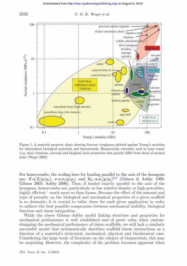
Current tissue scaffolds not only differ structurally from biological materials,but they are also mechanically and chemically very different from the naturaltissue for which they substitute. Figure 1, a material property chart plottingfracture toughness against Young’s modulus for natural mineralized tissues andbiomaterials, allows us to compare mechanical properties and performance.Metals such as steel and titanium (red) both have a Young’s modulus and atoughness significantly higher than those of natural bone. Fully dense ceramicssuch as zirconia and bioglass (blue) have a toughness similar to that of naturalbone (yellow), but too high a Young’s modulus. The components (green) ofmineralized biological materials, such as hydroxyapatite (e.g. in bone, dentin,enamel and antler) and calcium carbonate in the form of calcite or aragonite (e.g.in nacre), have, as bulk materials, a higher Young’s modulus, but a significantlylower toughness than both compact bone and engineering ceramics.
Additionally, synthetic bone substitute materials are frequently monolithic.In contrast, biological ceramics, such as bone, dentin, enamel, antler and nacre(yellow and light blue), achieve their unique property combination and anamplification of their components’ mechanical properties owing to their composite
Phil. Trans. R. Soc. A (2010)
on August 6, 2018http://rsta.royalsocietypublishing.org/Downloaded from
Biomaterials by freeze casting 2101
structure and architecture. The stiffness of the composite derives from the mineralnano- and microparticles, the fracture resistance from a brick-and-mortar-likemicrostructure in which the polymeric mortar phase transfers loads and absorbsenergy (Gao et al. 2003; Fratzl & Weinkamer 2007).
Bone, in which collagen fibrils are mineralized with hydroxyapatite (45 wt% inmature bone (Taylor 2003)), is also an excellent example of a porous biologicalmaterial. It is the introduction of porosity that further allows tailoring ofotherwise single-value physical and mechanical properties. Figure 1 illustratesthat the properties of dense cortical or compact bone are almost two magnitudeshigher than those of highly porous cancellous (trabecular or spongy) bone thatfills the medullary cavities of the femur and skull. It is thus the microstructure of aporous composite material that allows bone to fulfil two particularly important,but contradictory, design requirements: to provide a large overall porosity andsufficiently high mechanical properties such as stiffness, strength and toughness.
A promising route for the synthesis of bone substitute materials thus emerges:to mimic the hierarchical composite structure and porosity of the natural tissuebecause this approach will allow to custom design material properties at severalstructural length scales so that the biomaterial can simultaneously and optimallyfulfil biological and mechanical requirements.
3. Porous materials
In a first-order approximation, two types of porous materials can be distinguished:foams and honeycombs. Foams consist of spherical or equiaxed pores and haveisotropic properties, whereas honeycombs consist of highly aligned, prismaticpores that result in anisotropic properties. The main difference between thesetwo porous materials is that the deformation of foams is bending-dominated,which means that they exhibit a post-yield stress–strain curve with a long, flatplateau, whereas that of honeycombs is stretch-dominated, showing initial yieldfollowed by brittle collapse or plastic buckling (Gibson & Ashby 1999; Gibson2005; Ashby 2006). For a given relative density of the material r/rs, where r isthe density of the cellular material divided by the density rs of the solid materialfrom which it is made, both the elastic modulus and the initial collapse strengthare significantly greater in a stretch-dominated honeycomb structure than those ina bending-dominated foam. This is why honeycombs are particularly efficient forstructural applications in which a high overall porosity is desirable and anisotropyis acceptable, as is the case in biomaterials.
The three most important factors that influence the properties of a cellularscaffold material are: (i) the properties of the solid from which the scaffold ismade, (ii) the cell geometry, and (iii) the relative density r/rs of the scaffold(Gibson & Ashby 1999; Gibson 2005; Ashby 2006). For foam-like structures inwhich the pores can be considered equiaxed, Young’s modulus E typically scaleswith Young’s modulus Es of the solid from which it is made as E ∝ Es(r/rs)2, andits compressive strength s typically scales as s ∝ ss(r/rs)3/2, with ss being theyield strength (if the cell-wall material is ductile) or the modulus of rupture (ifthe cell-wall material is brittle) of the solid from which it is made. The fracturetoughness KIC of a cellular scaffold is more difficult to model, but typicallyscales as KIC ∝ ss(r/rs)3/2 with the failure strength of the cell-wall material.
Phil. Trans. R. Soc. A (2010)
on August 6, 2018http://rsta.royalsocietypublishing.org/Downloaded from
2102 U. G. K. Wegst et al.
Young’s modulus (GPa)0.1 1 10 100
frac
ture
toug
hnes
s (M
Pa m
1/2 )
0.1
1
10
100
NATURALMINERALS
silver amalgam
titanium
precious metals implants
nickel–chromium alloys stainless steel
cobalt–chromium alloys
zirconia
cortical bone (l)
dentineNATURAL
MINERALIZEDTISSUES
METALS
cancellous bone (low density)
cancellous bone (high density)
egg shell
coral
antler
enamel
cortical bone (t) bioglassceramic
biosilica(spongespicule)
calciumphosphate
hydroxyapatite calcite
silica(synthetic)
aragonite
vitreouscarbon
BIO-CERAMICS
NACRE
Figure 1. A material property chart showing fracture toughness plotted against Young’s modulusfor mineralized biological materials and biomaterials. Biomaterials currently used in bone repair(e.g. steel, titanium, zirconia and bioglass) have properties that greatly differ from those of naturalbone (Wegst 2009).
For honeycombs, the scaling laws for loading parallel to the axis of the hexagonsare: E ∝ Es(r/rs), s ∝ ss(r/rs) and KIC ∝ ss(r/rs)3/2 (Gibson & Ashby 1999;Gibson 2005; Ashby 2006). Thus, if loaded exactly parallel to the axis of thehexagons, honeycombs are, particularly at low relative density or high porosities,highly efficient—much more so than foams. Because the effect of the amount andtype of porosity on the biological and mechanical properties of a given scaffoldis so dramatic, it is crucial to tailor these for each given application in orderto achieve the best possible compromise between mechanical stability, biologicalfunction and tissue integration.
While the above Gibson–Ashby model linking structure and properties formechanical performance is well established and of great value when custom-designing the mechanical performance of tissue scaffolds, we still lack a similarlysuccessful model that systematically describes scaffold–tissue interactions as afunction of a material’s structural, mechanical, physical and biochemical cues.Considering the large body of literature on the subject of biomaterials, this maybe surprising. However, the complexity of the problem becomes apparent when
Phil. Trans. R. Soc. A (2010)
on August 6, 2018http://rsta.royalsocietypublishing.org/Downloaded from

Biomaterials by freeze casting 2103
realizing that even a seemingly simple property such as porosity cannot currentlybe described in a way that fully captures what a cell senses. Research attemptingto correlate pore diameter, pore curvature, pore aspect ratio, pore surface area-to-volume ratio, connectivity, surface roughness, surface chemistry, which isinterdependent with geometry, and cell responses to these are ongoing. Onceestablished, such property correlations are expected to greatly aid tissue-scaffolddevelopment.
Biomaterials made by freeze casting, a process that takes advantage of theprinciple of directional solidification of a liquid vehicle such as water and istherefore also known as ‘ice-templating’, are ideally suited to contribute toa systematic study linking structural features to cell responses. They offerparticular potential for such research because all classes of materials (polymers,ceramics, metals and composites) can be prepared by this process, and becausemany of the properties of the hierarchical structures produced can be varied in acarefully controlled fashion for one given material composition.
4. The process of freeze casting
Interest in the effect of freezing on solutions and suspensions dates back at leastto the beginning of the twentieth century, when first qualitative observationswere reported by, for example, Bobertag et al. (1908) and Lottermoser (1908).Lottermoser was probably among the first who described the formation ofmaterials with honeycomb structures upon freezing. Bobertag et al. (1908)noted structural changes in the first frozen, then remelted material, which, theysuggested, are due to the expanding ice crystals exerting forces on the matter,which, upon freezing, is expelled from the liquid carrier and trapped between thecrystals. About 50 years later, Maxwell et al. (1954) described freeze casting aswe understand it today. They reported the successful preparation of intricatelyshaped objects such as turbocharger blades from an extremely thick ceramic slipby casting, freezing and liquid sublimation before sintering.
Initially, freeze casting was identified by Maxwell et al. (1954), as a means tomanufacture exceptionally dense ceramics with minimal shrinkage for technicalapplications. Three decades later, Tong et al. (1984) and Tong & Gryte (1985)applied the technique to a water-soluble polymer; they created, from agar gels,highly porous materials with a well-controlled cellular architecture and studiedthe effect of freezing velocity and diffusion conditions on pore geometry. Morerecently, the potential of freeze casting as a means to create ceramics witha controlled and complex cellular architecture has started to attract researchattention (Fukasawa et al. 2001, 2002), and the first reports on freeze-castbiomedical materials prepared from collagen solutions have appeared (Schoofet al. 1998, 2000, 2001; von Heimburg et al. 2001; Kuberka et al. 2002). Freezecasting of ceramic-based biomaterials followed (Chow et al. 2001; Araki &Halloran 2005; Zhang et al. 2005; Deville et al. 2006a; Deville 2008; Fu et al.2008a,b; Macchetta et al. 2009). Most recently, freeze casting of the first metal,titanium, has been reported (Chino & Dunand 2008; Yook et al. 2008, 2009; Fifeet al. 2009). Current research focuses on both the fundamentals of the freeze-casting process, drawing on the well-established field of directional solidificationof alloys, and the properties of the materials created (Deville 2008).
Phil. Trans. R. Soc. A (2010)
on August 6, 2018http://rsta.royalsocietypublishing.org/Downloaded from
2104 U. G. K. Wegst et al.
One reason for freeze casting having quickly gained popularity as amanufacturing route for biomaterials is that it is a comparatively straightforward,physical process, based on benign, biocompatible liquid carriers such as water.Another reason is that the structure of freeze-cast materials, such as their overallporosity, pore size and pore geometry, can easily be controlled across severallength scales. Of equal importance is the ability to custom design both during andafter freeze casting the scaffold’s cell-wall properties, such as surface roughnessand chemistry, and with it the interface properties that are of critical importanceto tissue–material interactions and a scaffold’s successful tissue integration. Thesestructural features, combined with the remarkable mechanical properties thatdirectionally solidified materials offer despite their high overall porosity, are thebasis of the great promise of freeze-cast biomaterials.
Because all classes of materials can be processed, a great range of potentialapplications for freeze-cast biomaterials exists: collagen scaffolds, for example, arebeing explored for use in the peripheral nervous system and spinal-cord repair(Bozkurt et al. 2007; Moellers et al. 2009), in which excellent pore alignment,pores diameters of 10–50 mm and Young’s modulus of 1–10 kPa are required(Bilston & Thibault 1996; Ozawa et al. 2001); calcium phosphate (hydroxyapatite,tricalcium phosphate and composites of the two) scaffolds with pore diameters of100–500 mm, Young’s modulus of 0.05–1 GPa and a strength of more than 50 MPaare investigated for bone substitution in low to medium load-bearing applications(Saiz et al. 2008).
Great potential for freeze-cast biomaterials also exists in applications in whichporosity is not required. By filling the pores with a second phase, ceramic–polymeror ceramic–metal composites can be created that, similar to their biologicalcounterparts (compact bone and nacre), have a toughness several magnitudeshigher than that of their constituents (Munch et al. 2008). Freeze casting is furtherideally suited for the manufacture of materials with property gradients. It is thusa process with great promise for the development of biomimetic biomaterialsthat emulate several design principles of the natural tissue that they are designedto replace.
5. Processing biomaterials by freeze casting
Freeze casting is a physical process. This is why all classes of materialsand composites made from them can, in principle, be prepared by freezingpolymer solutions, metal or ceramic particle suspensions or novel micro- andnanocomposites consisting of polymer, ceramic or metal fibres and particles in apolymer solution. While the majority of freeze-cast materials is still preparedusing aqueous solutions or slurries, other liquid vehicles, such as camphene(Sofie & Dogan 2001; Araki & Halloran 2005; Shanti et al. 2006; Lee et al.2007a,b; Yoon et al. 2007; Yook et al. 2008, 2009), camphene–naphthalene(Araki & Halloran 2004a) and tert-butyl alcohol (Chen et al. 2007), are alsoincreasingly being used. Important in the choice of the liquid carrier are propertiessuch as its crystal structure and type of growth during solidification and itsinteraction with the solids dissolved or suspended in it. This is to ensure that ahomogeneous dispersion can be achieved from which a material with the desiredhomogeneous microstructure can be formed by precisely controlling the processing
Phil. Trans. R. Soc. A (2010)
on August 6, 2018http://rsta.royalsocietypublishing.org/Downloaded from

Biomaterials by freeze casting 2105
parameters. Because the freeze casting of ceramic particle suspensions, slurries orslips by directional solidification is, to date, the most studied, we will concentrateon these in the following sections. The principles described are, however, equallyapplicable to metal particle suspensions and polymer solutions.
(a) Slurry properties
Ceramic slurries for freeze casting are typically composed of micro- orsubmicrometre-sized particles suspended in water to which dispersants (e.g.Darvan C, R.T. Vanderbilt Co, Norwalk, CT, USA) and binders (e.g. polyvinylalcohol) are commonly added (Deville et al. 2006b). Dispersants, which can beanionic, cationic or neutral and which depend on the liquid carrier and particlessuspended in it, reduce particle aggregation and flocculation (Fu et al. 2008b,c).Both are undesirable because they lead to heterogeneities in the final product andthey change the slurry’s physical properties such as its sedimentation behaviourand viscosity.
For a given particle size, the viscosity depends on the type of interactionbetween particles and liquid carrier, whether by van der Waals forces, hydrogenbonds or polar interactions. For a given type of interaction, the viscosity dependson the particle size. In the case of van der Waals forces, for example, theforces grow with molecular weight and particle size; the higher the molecularweight or the larger the agglomerate, the higher the forces and the higher theviscosity. For a given particle size, an increase in solid-volume fraction hasthe same effect, because the particles are more closely packed, resulting in moreand stronger particle–particle interactions increasing the resistance to flow. Theviscosity of the slurry is a particularly important processing parameter in freeze-casting. It determines, for a given particle size, both the velocity of sedimentationand the critical freezing-front velocity at which particle trapping occurs duringsolidification. Viscosity is thus a structural parameter that determines thematerial’s structural and mechanical properties.
Binders are added to the slurry to increase the strength of the greenceramic bodies before sintering or to form composite materials for which furtherprocessing is not necessary.
(b) Sedimentation
Through the careful control of particle sedimentation, which depends onthe particle’s density and size distribution and the liquid vehicle’s density andviscosity, it is possible either to avoid or to deliberately generate before and duringfreezing structural gradients within a sample. When a spherical particle of radiusr and mass m is immersed in a fluid of density rL, it will experience two forces,one due to the gravitational acceleration g = 9.807 m s−2 and a force opposing it,which, according to Archimedes’ principle, is equal to the weight of the volumeV of the fluid that it displaces. The resulting force on the sphere is
F = (m − rLV )g = (rP − rL)g43
pr3. (5.1)
If the sphere’s density is higher or lower than that of the fluid in which it isimmersed, it will, according to Stokes’s law, experience a frictional force resistingits motion. This resisting force depends on the dynamic viscosity h of the liquid
Phil. Trans. R. Soc. A (2010)
on August 6, 2018http://rsta.royalsocietypublishing.org/Downloaded from
2106 U. G. K. Wegst et al.
vehicle and both the radius and the velocity nP of the particle,
Ff = 6prhnP. (5.2)
Equating expressions (5.1) and (5.2) and solving for the velocity nP, the particle’sterminal velocity of the sphere can be calculated,
nP = 2(rP − rL)g9
r2
h. (5.3)
Thus, to ensure minimal sedimentation, the density difference between the sphereand liquid needs to be minimized, and, for a given material pairing and terminalvelocity, the viscosity needs to increase quadratically with an increase in theparticle diameter.
Stokes’s law neglects particle–particle interactions and only applies to laminarflow, a type of fluid flow in which adjacent layers do not mix, except on themolecular scale. The transition from laminar to turbulent flow occurs at a criticalvelocity
ntrans = Reh
2rLr(5.4)
and Reynolds numbers Re < 0.2. Inserting Re = 0.2 into equation (5.4) andequating it with equation (5.3), the maximum particle radius for laminar flowcan be calculated as
rmax =(
0.45h2
(rP − rL)rLg
)1/3
. (5.5)
For a suspension of hydroxyapatite (rP = 3150 kg m−3) spheres in 0◦C water(rL = 999 kg m−3 and h = 1.793 mPa s), the maximum radius for laminar flow isapproximately 41 mm. The terminal sedimentation velocity of such a particleis 4.4 mm s−1. Diameters of hydroxyapatite particles used in freeze casting aretypically much smaller than this, ranging from 100 nm to 2 mm (Lee & Shin 2007;Moritz & Richter 2007; Suetsugu et al. 2007; Yoon et al. 2007; Deville 2008). Theyare thus in the laminar-flow regime, and their sedimentation velocities range from26 nm s−1 to 11 mm s−1, respectively.
6. The freezing process
Once a slurry with appropriate sedimentation properties has been prepared,it is degassed and filled into a mould, which is typically made frompolytetrafluoroethylene (PTFE) and sealed by a copper bottom plate (figure 2).The slurry may be degassed once again before the mould is placed on the coppercold finger for directional freezing. Most experiments described in the literatureuse a one-sided freezing system in which the top of the mould remains open(e.g. Deville et al. 2006a; Fu et al. 2008a; Pekor et al. 2008). The advantage oftwo-sided freeze-casting systems, in which the bottom and top of the mould areclosed by copper plates whose temperature can be varied independently, is thatthe temperature gradient and freezing-front velocity within the sample can bebetter controlled (Deville et al. 2006a,c; Waschkies et al. 2009). In both systems,
Phil. Trans. R. Soc. A (2010)
on August 6, 2018http://rsta.royalsocietypublishing.org/Downloaded from

Biomaterials by freeze casting 2107
polymer (PTFE) tube
ceramic suspension/metal suspension/polymer solution
ice lamella
thermocouple
copper cold finger
ceramic particle/metal particle/polymer lamellae
heat flux
freezing direction
cooled plate
heating elements
liquid nitrogen bath
Figure 2. Schematic of the freeze-casting system. The sample solution or slurry is poured into aPTFE mould and placed with its copper bottom plate onto the copper cold finger. The coppercold finger is cooled by a liquid nitrogen bath; temperature and cooling rate at the mould bottomplate are controlled using a band heater.
a resting period before freezing is frequently used either to adjust the overallsample temperature to a given value close to the solidification temperature or tocreate a well-defined temperature gradient within it.
To freeze the sample, the heating applied to the cold finger is reducedin a controlled fashion with typical cooling rates ranging from 0.1◦C min−1
to 10◦C min−1. In most freeze-casting systems, the applied cooling rate ismeasured at the cold-finger–sample interface, but not the velocity of the freezingfront during processing itself. However, in systems that are equipped with athermocouple array embedded in the mould, the freezing-front velocity can bemeasured directly and the cold-finger cooling rate adjusted to achieve a desiredvalue (Waschkies et al. 2009). Once the temperature of the cold finger is lowerthan the solidification temperature of the slurry, a freezing front, defined as theinterface between the solid and the liquid phases, is formed and starts to travelthrough the sample. How the applied cooling rate and the freezing-front velocitywithin the sample are correlated will be discussed below.
Both the freezing-front velocity and the form in which the liquid vehiclecrystallizes determine sample structure and mechanical properties. An importantcriterion for the selection of the liquid vehicle is, among others, whether it willsolidify in a dendritic or a faceted manner. This can be predicted by the liquidvehicle’s a-value (Jackson & Hunt 1965; Araki & Halloran 2004b, 2005)
a = hEx
RTE, (6.1)
Phil. Trans. R. Soc. A (2010)
on August 6, 2018http://rsta.royalsocietypublishing.org/Downloaded from

2108 U. G. K. Wegst et al.
where hE is the latent heat, R is the gas constant, TE is the equilibriumtemperature between the two phases and x is a factor that depends on thecrystallography of the interface. The value of x typically ranges from 0.5 to 1for the closest packed face of a crystal and decreases for higher index planes.The factor hE/RTE is the entropy of melting. Materials that have a value of a < 1grow in a dendritic fashion. Water and camphene, the most commonly used liquidvehicles used in freeze casting, have hE/RTE values of approximately 2.6 and 1.1,respectively, and show dendritic growth (Araki & Halloran 2005).
While water and camphene are similar in that they both grow dendrites,they greatly differ in their crystal structure. Under ambient temperature andpressure conditions, camphene forms cubic crystals with an isotropic structure,whereas water solidifies into anisotropic hexagonal ice crystals with a crystalgrowth velocity that is approximately 100 times faster in the a-direction of thehexagonal base than perpendicular to it in the c-direction (Petrenko & Whitworth2002). As a result, ice crystals grow with a lamellar microstructure parallel to thea-direction during freeze casting. When the crystal growth conditions result invery small lamellar spacing, owing to a high freezing-front velocity, for example,the growth rate in the c-direction can be sufficiently large for bridges to be formedbetween the lamellae. Such bridges are often desirable because they significantlystiffen and strengthen the freeze-cast material.
(a) Particle trapping and rejection
The velocity of crystal growth during solidification defines the freezing-frontvelocity, which determines whether a particle in the slurry will be rejected andpushed ahead, or engulfed and trapped by the approaching liquid–solid interface.The other important factor is the balance between two opposing forces that acton each particle: a repulsive force, which keeps the particle in the liquid phaseowing to the system’s resistance against a change in the surface energy, andan attractive force that, due to viscous drag, pushes the particle towards thesolid–liquid interface (figure 3).
Thermodynamically, a particle can only be trapped if the free energy of thesystem Ds0 is negative
Ds0 = sps − (spl + ssl) < 0, (6.2)
where sps, spl and ssl are the surface energies between the particle and the solid,the particle and the liquid and the solid and the liquid, respectively. Thus, theparticle will be engulfed and trapped, if the energy of the newly formed particle–solid surface is smaller than the sum of the energies of the particle–liquid andthe solid–liquid surfaces that disappear from the system; otherwise, the particleremains in the liquid (Körber et al. 1985; Asthana & Tewari 1993).
In the liquid phase, a particle with radius r experiences a repulsive force owingto molecular van der Waals interactions at the solid–liquid interface
FR = 2prDs, (6.3)
where
Ds = Ds0
(a0
d
)n, (6.4)
Phil. Trans. R. Soc. A (2010)
on August 6, 2018http://rsta.royalsocietypublishing.org/Downloaded from

Biomaterials by freeze casting 2109
liquidphase
solidphase
deformedinterface
particletrapping:
particlerejection:
solutediffusion
fluidflow
d
r
v
FRσsl
σpl
σps
Fη
Dσ0d
3hrncr > n =
na0
d
Dσ = σps
− (σpl
+ σsl
) > 0
Figure 3. Schematic of particle–freezing-front interactions. A particle of radius r separated fromthe solid–liquid interface by a liquid film of thickness d experiences an attractive force Fh and arepulsive force FR. Balancing the forces, a critical freezing-front velocity v can be calculated, abovewhich the particle will be engulfed and trapped, and below which the particles will be rejected andpushed ahead by the solid–liquid interface.
in which Ds0 is the free energy of the system, a0 is the mean distance between themolecules in the liquid layer and d is the thickness of the liquid layer between theparticle and the solid–liquid interface. The term in brackets with exponent n is acorrection to the repulsive forces that act on the particle; values for n typicallyrange from 1 to 4 (Uhlmann et al. 1964; Körber et al. 1985; Zhang et al. 2005).Neglecting this correction by assuming n = 1, the repulsive force acting on theparticle becomes
FR = 2prDs0
(a0
d
). (6.5)
In addition to this repulsive force, the particle also experiences an attractive forceowing to viscous drag. The expression for the viscous-drag force is derived fromStokes’s law (equation (5.2)) and adapted to the specific case of a thin film ofthe liquid that fills the gap between the solid–liquid interface of the freezing frontand the particle (Bolling & Cisse 1971; Stefanescu et al. 1988),
Fh = 6phnr2
d. (6.6)
From an equilibrium of repulsive and attractive forces, a critical velocity ncr of thefreezing front can be calculated at which particle entrapment takes place (Lipp &Körber 1993; Zhang et al. 2005),
ncr = Ds0a0
3hr. (6.7)
At freezing-front velocities below this value, the particles are pushed ahead bythe solid–liquid interface.
Phil. Trans. R. Soc. A (2010)
on August 6, 2018http://rsta.royalsocietypublishing.org/Downloaded from

2110 U. G. K. Wegst et al.
Experimentally, significant differences were observed by Azouni et al. (1990)and Yemmou et al. (1993) in the encapsulation process in the dependence of thethermal conductivity ratio
m = lP
lL, (6.8)
where lP and lL are the thermal conductivities of the particles and the liquidvehicle, respectively. Particles that have a lower thermal conductivity than theliquid result in a convex bending of the interface towards the particle; particleswith a higher thermal conductivity than the liquid cause a concave deformationof the interface away from it. Theoretically, this phenomenon was described byShangguan et al. (1992) and Sen et al. (1997). To account for it, Lipp & Körber(1993) suggest a modified expression for the critical velocity,
ncr = Ds0a0
12hmr. (6.9)
Critical freezing-front velocities for hydroxyapatite particles in water canbe estimated using this expression and typical values for the variables areDs ≈ ssl ≈ 0.1 J m−2, a0 = 10 nm, h = 1.793 mPa s and m = 1.8; for particles withradii ranging from r = 0.10 mm to r = 2 mm, they range from vcr = 0.26 m s−1 tovcr = 0.013 m s−1, respectively.
In addition to differences in thermal conductivity between particles andliquid, which cause undulations of the solid–liquid interface, local changes inthe slurry’s concentration ahead of the solid–liquid line lead to instabilitiesin the freezing front. Assuming that the freezing front that emerges fromthe mould–liquid interface is plane and that its velocity is below the criticalvelocity, particles will be rejected. As a consequence, a concentration gradientforms in the slurry immediately ahead of the freezing front, which results in azone with an increased particle concentration and decreased solidification point,the constitutional undercooling zone. When this finally breaks down, Mullins–Sekerka instabilities (Mullins & Sekerka 1964) are formed with a wavelength thatdetermines the lamellar spacing between the ice crystals (Butler 2001, 2002a,b;Zhang et al. 2005). The architecture observed in freeze-cast samples providesexperimental support of the structural differences predicted by freezing-frontvelocity considerations.
(b) Structural effects of the freezing-front velocity
Azouni et al. (1997) monitored the unidirectional freezing process in doublydistilled water with a shadow graph, in which thermal disturbances refract lightand the resulting shadows image the thermal flow. They observed that varying thefreezing rate resulted in three distinctly different ice structures; first, a dense icelayer followed by an intermediate columnar zone and finally a lamellar structurewith highly aligned porosity. Deville et al. (2007) observed the same three distinctstructural regions in bulk materials freeze cast from ceramic slurries.
Initially, when the cooling rate is fast, a plane ice front of high velocityemerges, which traps the particles, thereby forming a relatively dense andhomogeneous layer. Gradually, the freezing-front velocity slows owing to aninsulating layer of solid being formed. The plane solid–liquid interface starts toundulate owing to interactions with the particles close to the solid–liquid interface
Phil. Trans. R. Soc. A (2010)
on August 6, 2018http://rsta.royalsocietypublishing.org/Downloaded from

Biomaterials by freeze casting 2111
and particle rejection, which causes constitutional undercooling. As a result, theslurry solidifies with a columnar structure. On further slowing of the freezing-front velocity, local ‘pinning’ of the solid–liquid interface with a well-definedwavelength causes the transition from the columnar to the final, highly orderedlamellar structure. Gradually, the ice lamellae, which may initially be slightlyinclined, align with the preferred growth direction parallel to the temperaturegradient. They extend fast along their a-axis and very slowly along their c-axis.The lamellar structure that they create dominates the rest of the length of thesample. It is the desired structure for biomedical applications. Empirically, thelamellar spacing w has been found to vary with the freezing-front velocity v as
w ∝ 1nn
, (6.10)
where n ranges from 1 to 4 (Deville et al. 2007). Because the freezing-front velocityis such an important processing parameter, it is critical to be able to carefullycontrol it.
(c) Control of freezing-front velocity
The freezing-front velocity, and with it the time it takes to solidify an entiresample, primarily depend on two quantities: the temperature gradient betweenthe solidifying layer in the sample and the copper cooling plate and the thermalproperties of the solid phase that has already formed. When a layer of thicknessds of a liquid solidifies at its thermal transition temperature TE, the solidificationenthalpy hE is set free as heat, and has to be conducted away through thesolid phase to the cooled surface. How quickly this heat can be conducted awaydetermines the speed of solidification and thus the velocity at which the freezingfront travels.
Assuming that, at x = 0, the temperature is kept constant at a temperatureT0 < TE, and neglecting heat storage in the solidified material, which ispermissible because, with a specific heat c = 2.11 J g−1◦C−1 and latent heathE = 333.6 J g−1, ice has a phase-transition number (ratio between latent heatand difference in internal energies of the solid at TE and T0) of
Ph = hE
c(TE − T0)> 7, (6.11)
and a quasi-static approximation of the solidification time, which alwaysunderestimates the actual solidification time, can be calculated (Stefan problem)(Baehr & Stephan 2003) as
t = rLhE
2lL(TE − T0)s2, (6.12)
for a liquid vehicle with density rL and thermal conductivity lL.This approximation permits to assume different boundary conditions at the
cooled end of the solid and to describe the solidification of a liquid at the surfaceof a cooling plate of thickness dC and thermal conductivity lC, which is cooledby a liquid of temperature T0 and which has the heat-transfer coefficient a.Under these conditions, at a given time t, a solid layer of thickness s, densityrS and thermal conductivity lS is formed. The heat freed during solidification is,
Phil. Trans. R. Soc. A (2010)
on August 6, 2018http://rsta.royalsocietypublishing.org/Downloaded from

2112 U. G. K. Wegst et al.
as before, conducted away through both the solid layer and the plate. Assumingquasi-static conditions and equating the heat generated during solidification withthat transferred, the progression of the freezing front can be described as (Baehr &Stephan 2003)
dt = rhE
lS(TE − T0)
(s + lS
k
)ds, (6.13)
where the heat-transfer resistance
1k
= dC
lC+ 1
a(6.14)
is, in our case, that of the copper bottom plate of the freeze-casting mould.The velocity at which the solidification front progresses is
n(s) = dsdt
= lS(TE − T0)rhE
(s + lS
k
)−1
. (6.15)
Integrating equation (6.13) yields an expression for the solidification time t of alayer of thickness s
t(s) = rhE
lS(TE − T0)
(s2
2+ lS
ks)
. (6.16)
For very thin plates dC → 0, 1/k → 0 and the result equals that of the above-described Stefan problem. For plates with a finite thickness and a heat-transferresistance 1/k > 0, solidification is slower.
To achieve a constant freezing-front velocity
n = lS(TE − T0)rhE
(s + lS
k
)−1
= const. (6.17)
throughout the sample, the temperature T0 of the cooling bottom plate has tobe varied as
T0(t) = TE − n2rLhE
lS
(t + lS
nk
). (6.18)
The last unknown in this equation is the thermal conductivity of the solidifiedslurry.
(d) Thermal conductivity of the freeze-cast solid
To calculate the thermal conductivity of the solidified slurry, which consistsof pure-ice lamellae that alternate with lamellae that consist of a particle–icecomposite, we assume the latter to be packed beds, in which the particles arerandomly close packed. The thermal conductivity of the packed bed lB can be
Phil. Trans. R. Soc. A (2010)
on August 6, 2018http://rsta.royalsocietypublishing.org/Downloaded from

Biomaterials by freeze casting 2113
lP
ψ
ψ
1 – ψ
1 – ψ
ψ1 – ψ
a
1 – a
lB
lP
s xT0
T
0
TE
dC
solidified layer
a
copp
er p
late
liquid
lS
lI
lI
lI
(a)
(c)
(b)
Figure 4. Graphical representation of the Krischer–Kröll model used to calculate the thermalconductivity of (a) the packed bed and (b) the lamellar solid. (c) Temperature profile in thesample during directional solidification, which starts at the copper bottom plate (x = 0) of themould.
described according to the Krischer–Kröll model (Krischer & Kröll 1956) as anarrangement of serial and parallel components,
lB = lI
(1 − a)(j + (1 − j)(lP/lI))−1 + a(j + (1 − j)(lI/lP)), (6.19)
where the parameter a describes the amount of the serial component, j isthe volume fraction of the continuous pure-ice phase and lP and lI are thethermal conductivities of the particles and the pure ice, respectively, as shown infigure 4 (Krischer & Kröll 1956; Tsotsas & Martin 1987). Assuming the packedbed to consist of 64 vol% particles and 36 vol% ice, Tsotsas & Martin (1987)suggest to use a = 0.2 for an appropriate description of its thermal conductivity.Using these values and the material properties listed in table 1, the thermalconductivity of a single packed-bed lamella of hydroxyapatite is calculated tobe lB = 1.16 W m−1 K−1.
At the next higher level of the structural hierarchy, the freeze-cast materialconsists of highly aligned, alternating lamellae of packed-bed material and pureice that have the thermal conductivities lB and lI, respectively. Assuming thelamellae to be perfectly parallel to the direction of heat flow, the thermal
Phil. Trans. R. Soc. A (2010)
on August 6, 2018http://rsta.royalsocietypublishing.org/Downloaded from

2114 U. G. K. Wegst et al.
Table 1. Properties of water, ice and hydroxyapatite.
latent specific heatsolidification heat of thermal at constant
density r temperature fusion conductivity l pressure cp viscositymaterial (kg m−3) TE (◦C, K) hE (J g−1) (W m−1 K−1) (J g−1◦C−1) h (mPa s)
water at 0◦C 0.99984 0, 273.16 333.6 0.561 4.2176 1.793ice at 0◦C 0.9167 0, 273.16 333.6 2.14 2.11 —hydroxyapatite 3.150 — — 0.77 — —
Table 2. Volume fraction of pure-ice lamellae j and thermal conductivity lS of the solidifiedcomposite consisting of a parallel arrangement of particle-bed and pure-ice lamellae.
hydroxyapatite (vol%)slurry properties 5 10 20 30 40 50
j 0.92 0.84 0.69 0.53 0.37 0.22lS (W m−1 K−1) 2.06 1.99 1.83 1.68 1.53 1.38
conductivity of the freeze-cast solid may be described by a = 0. With thisassumption, the expression for the thermal conductivity reduces to the rule ofmixture
lS = jlI + (1 − j)lB, (6.20)
where j, as before, is the volume fraction of the pure-ice lamellae. It should benoted that this value of j differs from the overall volume fraction of ice in thesolid when calculating the thermal conductivities of the freeze-cast material. Thisis because 36 vol% of the particle bed is formed by the ice matrix in which theparticles are embedded. As a result, a slurry that contains a 10 vol% fractionof hydroxyapatite will form a structure that consists of 15.6 vol% of particle-bed lamellae and 84.4 vol% of pure-ice lamellae. To illustrate this, the thermalconductivities lS of solidified slurries with hydroxyapatite particle loadingsranging from 5 to 50 vol% are calculated using the material properties of table 1and listed in table 2.
(e) Lamellar surface roughness control through additives
At the next lower level of the hierarchy, the lamellar surface roughness playsan important role in biomaterials design, as it is known to greatly affect tissue-scaffold interface properties. Munch et al. (2009) explored this through the useof chemical additives that are known to affect the interfacial energies, growthkinetics and microstructure of ice, as well as the topology of the ice–waterinterface. Most of the additives used by Munch et al. (2009) form a eutecticphase diagram with water, resulting in the modification of the solvent thatbroadens the number of possible pore-shape morphologies. Their results indicate
Phil. Trans. R. Soc. A (2010)
on August 6, 2018http://rsta.royalsocietypublishing.org/Downloaded from

Biomaterials by freeze casting 2115
temperature
pres
sure
1
2
3
12
3
polymer solutionor ceramic slurryis poured intomould at roomtemperature
as ice lamellaegrow, they forcepolymer moleculesand suspendedparticles into voids
frozen structure islyophilized,sublimating iceand generatingporosity
liquidsolid
vapour
Figure 5. Phase diagram illustrating the phase changes of the liquid vehicle (water here) duringthe freeze-casting process.
(a) (b)
Figure 6. Visualization of a cylindrical freeze-cast ceramic composite sample with a diameter of0.6 mm imaged by X-ray micro-tomography at a pixel resolution of 0.3 mm. Freezing rate: (a)20◦C min−1 and (b) 5◦C min−1.
that the microstructure can be altered from lamellar (e.g. no additives, trehaloseor sucrose) to cellular (e.g. gelatin, glycerol, sucrose with citric acid), or to alamellar structure with a bimodal pore-width distribution (ethanol). Additiveswere further shown to strongly modify the roughness of the ceramic walls. Theymay also aid the formation of bridges between the lamellae that result in improvedmechanical properties of the scaffolds.
Surprisingly, Munch et al. (2009) found, despite the obvious structuraldifferences, that the relationship between the structural wavelength and theaverage freezing-front velocity is almost independent of the additive used. Morework is needed, however, to assess the precise influence of additives on finalproperties and architectures of the scaffolds.
Phil. Trans. R. Soc. A (2010)
on August 6, 2018http://rsta.royalsocietypublishing.org/Downloaded from

2116 U. G. K. Wegst et al.
7. Freeze drying and further processing
After the freezing process is completed, the sample is carefully removed fromthe mould and lyophilized (freeze dried) for 24–48 h, depending on size, in orderto sublimate the ice from the structure (figure 5). Lyophilization parametershave not been found to significantly impact the final microstructure of freeze-cast samples. Because ceramic green bodies are generally very brittle afterlyophilization, they are usually sintered. Densification conditions, such astemperature and time, depend on the ceramic used and can be optimized toachieve a desired grain size and density.
8. Structure property correlations in freeze-cast materials
Surprisingly and despite significant research efforts, no exact design requirementsexist as to which combination of overall porosity, average pore size,pore connectivity, material surface roughness, surface chemistry, mechanicalproperties, etc. in a freeze-cast scaffold is best suited for each respective tissueor organ. The results of our ongoing systematic studies of such correlations areexpected to provide future guidance.
However, first structure–property linkages relating material architectureto mechanical performance for freeze-cast materials have been established.These correlations can already be influenced during slurry preparation becauseslurry composition and formulation have a significant effect on the scaffold’smicrostructure and subsequently its mechanical properties. In polar solvents,such as water, surface charges on particles are desirable because they aid particledispersion and thereby improve the homogeneity of the sample. Indirectly, theyalso affect other important processing parameters, such as the viscosity of theslurry and particle sedimentation, as these depend on the particle size. It ispossible to adjust surface charges through, for example, variations of the liquidcarrier’s pH and surface oxidation.
Additives in the slurry further allow to control the surface structure androughness of the lamellae created during the freezing process. The shape of thepores templated by the liquid carrier depends on the crystal type and growthcharacteristics with which it solidifies. This is why materials prepared with wateras the liquid vehicle have structures that greatly differ from those using camphene.
The amount of solid loading determines the overall porosity of the sample; thehigher the loading, the lower the overall porosity. Achievable overall porositiesdepend on the material used and range from approximately 40 to 97 vol% (Devilleet al. 2006a; U. G. K. Wegst 2009, unpublished data). The honeycomb-likestructure achieved by directional solidification results in mechanical propertiesthat are significantly higher than those achieved by non-directional freezing andlyophilization or other processing techniques that result in a foam-like material.Both Young’s modulus and the strength of honeycombs loaded parallel to thelong pore axis are predicted to scale linearly with the relative density of thematerial. The properties of freeze-cast ceramics approach this value and aresignificantly higher than those predicted for foams (Deville et al. 2006c). Fora given overall porosity, the lamellar thickness and spacing in a freeze-castmaterial can be controlled. An increase in the cooling rate to achieve an increase
Phil. Trans. R. Soc. A (2010)
on August 6, 2018http://rsta.royalsocietypublishing.org/Downloaded from

Biomaterials by freeze casting 2117
in the freezing-front velocity results in smaller lamellar spacing (figure 6a,b).As a common trend, a decrease in the lamellar spacing results in an increasein compressive strength (Hunger 2008). This is also thought to be due to anincreasing number of bridges between lamellae. However, different trends havealso been observed, particularly in freeze-cast polymers (U. G. K. Wegst 2009,unpublished data).
Because the porosity generated by freeze-casting is highly connected, it ispossible to create hierarchical microstructures by sequential freeze casting,thereby exploring the potential to introduce another level and another directionof porosity into the material. The high connectivity also makes it possible to coatthe sample once or several times and to infiltrate it with another phase. Bothoffer great potential to integrate into the biomaterial growth factors and otherbiochemical cues to stimulate tissue ingrowth.
9. Conclusion
Initially developed for the manufacture of highly dense ceramics, freeze casting, aprocess that uses the solidification of a liquid carrier such as water or camphene fortemplating, has, in recent years, been discovered as a route to create highly porousbiomaterials with complex, hierarchical architectures. Several reasons makefreeze casting highly attractive for the manufacture of materials for biomedicalapplications: all classes of materials, polymers, ceramics, metals and theircomposites can be shaped with it; the processing can be carried out with benign,biocompatible liquid carriers such as water; the hierarchical microstructurecreated can be carefully controlled by the physical and chemical properties ofthe components used and processing parameters such as freezing velocity.
The amount, type, size and geometry of the particles and the type of liquidcarrier determine the slurry’s viscosity and amount of sedimentation, as wellas the slurry’s thermal properties and freezing behaviour. In combination withthe freezing velocity and additives, these also determine pore connectivityand morphometry, such as the thickness and spacing of the lamellae andthe size and the number of the material bridges between them, the cell-wall’s bulk and surface properties, and thus both tissue–material interactionand mechanical properties of the freeze-cast honeycomb scaffolds. Materialcomposition and processing parameters further determine the anisotropy ratiobetween the strong and stiff freezing direction and the relatively weaker directionperpendicular to it. As a result, the freeze-casting process is ideally suited for thecustom-designed manufacture of complex, hybrid biomaterials with hierarchicalstructures. By freeze casting, it is possible to emulate in synthetic materialsmulti-level hierarchical composite structures that are thought to be the originof the mechanical-property amplification that is frequently observed in biologicalmaterials. Systematic studies are under way to correlate structure, mechanicaland chemical properties of freeze-cast scaffolds with tissue–interface formationand integration.
The authors thank Etienne Munch, Eduardo Saiz and Antoni P. Tomsia, Lawrence BerkeleyNational Laboratory, Berkeley, CA, USA, for very educational and stimulating discussions andthe provision of the samples depicted in figure 6. They are very grateful to Peter Cloetens,ESRF, Grenoble, France for his expert advice and support during their X-ray micro-tomography
Phil. Trans. R. Soc. A (2010)
on August 6, 2018http://rsta.royalsocietypublishing.org/Downloaded from
2118 U. G. K. Wegst et al.
experiments at ID19 and to the European Union for funding of their beam time. The authorsfurther wish to thank Thao Vi Le, Benjamin W. Riblett and Jenell R. Smith, Drexel University,Philadelphia, USA for experimental assistance. Finally, U.G.K.W. wishes to express her gratitudeto Anne J. Stevens for the generous support of her research and group.
References
Araki, K. & Halloran, J. W. 2004a Room-temperature freeze-casting for ceramics with nonaqueoussublimable vehicles in the naphthalene–camphor eutectic system. J. Am. Ceram. Soc. 87,2014–2019. (doi:10.1111/j.1151-2916.2004.tb06353.x)
Araki, K. & Halloran, J. W. 2004b New freeze-casting technique for ceramics with sublimablevehicles. J. Am. Ceram. Soc. 87, 1859–1863. (doi:10.1111/j.1151-2916.2004.tb06331.x)
Araki, K. & Halloran, J. W. 2005 Porous ceramic bodies with interconnected pore channelsby a novel freeze casting technique. J. Am. Ceram. Soc. 88, 1108–1114. (doi:10.1111/j.1551-2916.2005.00176.x)
Ashby, M. F. 2006 The properties of foams and lattices. Phil. Trans. R. Soc. A 364, 15–30.(doi:10.1098/rsta.2005.1678)
Asthana, R. & Tewari, S. N. 1993 Review: the engulfment of foreign particles by a freezinginterface. J. Mater. Sci. 28, 5414–5425. (doi:10.1007/BF00367810)
Azouni, M. A., Kalita, W. & Yemmou, M. 1990 On the particle behaviour in front of advancingliquid–ice interface. J. Cryst. Growth 91, 201–205. (doi:10.1016/0022-0248(90)90513-K)
Azouni, M. A., Casses, P. & Sergiani, B. 1997 Capture or repulsion of treated nylon particles byan ice–water interface. Colloid. Surf. A 122, 199–205. (doi:10.1016/S0927-7757(96)03747-8)
Baehr, H. D. & Stephan, K. 2003 Wärme- und Stoffübertragung (heat and mass transfer). Berlin,Germany: Springer.
Bilston, L. E. & Thibault, L. E. 1996 The mechanical properties of the human cervical spinal cordin vitro. Ann. Biomed. Eng. 24, 67–74. (doi:10.1007/BF02770996)
Bobertag, O., Feiat, K. & Fischer, H. W. 1908 Über das Ausfrieren von Hydrosolen. Ber. Dtsch.Chem. Ges. 41, 3675–3679. (doi:10.1002/cber.19080410353)
Bolling, G. F. & Cisse, J. 1971 A theory for the interaction of particles with a solidifying front.J. Cryst. Growth 10, 56–61. (doi:10.1016/0022-0248(71)90046-7)
Bozkurt, A. et al. 2007 In vitro assessment of axonal growth using dorsal root ganglia explantsin a novel three-dimensional collagen matrix. Tissue Eng. A 13, 2971–2979. (doi:10.1089/ten.2007.0116)
Butler, M. F. 2001 Instability formation and directional dendritic growth of ice studied by opticalinterferometry. Cryst. Growth Des. 1, 213–223. (doi:10.1021/cg005534q)
Butler, M. F. 2002a Freeze concentration of solutes at the ice/solution interface studied by opticalinterferometry. Cryst. Growth Des. 2, 541–548. (doi:10.1021/cg025591e)
Butler, M. F. 2002b Growth of solutal ice dendrites studied by optical interferometry. Cryst. GrowthDes. 2, 59–66. (doi:10.1021/cg0155604)
Chen, R., Wang, C. A., Huang, Y., Ma, L. & Lin, W. 2007 Ceramics with special porous structuresfabricated by freeze-gelcasting: using tert-butyl alcohol as a template. J. Am. Ceram. Soc. 90,3478–3484. (doi:10.1111/j.1551-2916.2007.01957.x)
Chino, Y. & Dunand, D. 2008 Directionally freeze-cast titanium foam with aligned, elongatedpores. Acta Mater. 56, 105–113. (doi:10.1016/j.actamat.2007.09.002)
Chow, K. S., Khor, E. & Wan, A. C. A. 2001 Porous chitin matrices for tissue engineering:fabrication and in vitro cytotoxic assessment. J. Polym. Res. Taiwan 8, 27–35. (doi:10.1007/s10965-006-0132-x)
Deville, S. 2008 Freeze-casting of porous ceramics: a review of current achievements and issues.Adv. Eng. Mater. 10, 155–169. (doi:10.1002/adem.200700270)
Deville, S., Miranda, P., Saiz, E. & Tomsia, A. P. 2006a Fabrication of porous hydroxyapatitescaffolds. In 2006 Proc. Int. Conf. on Manufacturing Science and Engineering. Ypsilanti, MI:American Society of Mechanical Engineers.
Phil. Trans. R. Soc. A (2010)
on August 6, 2018http://rsta.royalsocietypublishing.org/Downloaded from

Biomaterials by freeze casting 2119
Deville, S., Saiz, E. & Tomsia, A. P. 2006b Freeze casting of hydroxyapatite scaffolds for bonetissue engineering. Biomaterials 27, 5480–5489. (doi:10.1016/j.biomaterials.2006.06.028)
Deville, S., Saiz, E., Nalla, R. K. & Tomsia, A. P. 2006c Freezing as a path to build complexcomposites. Science 311, 515–518. (doi:10.1126/science.1120937)
Deville, S., Saiz, E. & Tomsia, A. P. 2007 Ice-templated porous alumina structures. Acta Mater.55, 1965–1974. (doi:10.1016/j.actamat.2006.11.003)
Fife, J., Li, J., Dunand, D. & Voorhees, P. 2009 Morphological analysis of pores in directionallyfreeze-cast titanium foams. J. Mater. Res. 24, 117–124. (doi:10.1557/jmr.2009.0023)
Fratzl, P. & Weinkamer, R. 2007 Nature’s hierarchical materials. Prog. Mater. Sci. 52, 1263–1334.(doi:10.1016/j.pmatsci.2007.06.001)
Fu, Q., Rahaman, M. N., Dogan, F. & Bal, B. S. 2008a Freeze-cast hydroxyapatite scaffolds for bonetissue engineering applications. Biomed. Mater. 3, 025005. (doi:10.1088/1748-6041/3/2/025005)
Fu, Q., Rahaman, M. N., Dogan, F. & Bal, B. S. 2008b Freeze casting of porous hydroxyapatitescaffolds. I. Processing and general microstructure. J. Biomed. Mater. Res. B 86B, 125–135.(doi:10.1002/jbm.b.30997)
Fu, Q., Rahaman, M. N., Dogan, F. & Bal, B. S. 2008c Freeze casting of porous hydroxyapatitescaffolds. II. Sintering, microstructure, and mechanical behavior. J. Biomed. Mater. Res. B 86B,514–522. (doi:10.1002/jbm.b.31051)
Fukasawa, T., Deng, Z. Y., Ando, M., Ohji, T. & Goto, Y. 2001 Pore structure of porousceramics synthesized from water-based slurry by freeze-dry process. J. Mater. Sci. 36, 2523–2527.(doi:10.1023/A:1017946518955)
Fukasawa, T., Deng, Z. Y., Ando, M., Ohji, T. & Kanzaki, S. 2002 Synthesis of porous siliconnitride with unidirectionally aligned channels using freeze-drying process. J. Am. Ceram. Soc.85, 2151–2155. (doi:10.1111/j.1151-2916.2002.tb00426.x)
Gao, H., Ji, B., Jäger, I. L., Arzt, E. & Fratzl, P. 2003 Materials become insensitive to flawsat nanoscale: lessons from nature. Proc. Natl Acad. Sci. USA 100, 5597–5600. (doi:10.1073/pnas.0631609100)
Gibson, L. J. 2005 Biomechanics of cellular solids. J. Biomech. 38, 377–399. (doi:10.1016/j.jbiomech.2004.09.027)
Gibson, L. J. & Ashby, M. F. 1999 Cellular solids: structure and properties. Cambridge, UK:Cambridge University Press.
Hunger, P. M. 2008 Freeze casting as method to create porous bonelike structures. Diploma thesis,Universität Karlsruhe, Germany.
Hutmacher, D. W. 2000 Scaffolds in tissue engineering bone and cartilage. Biomaterials 21, 2529–2543. (doi:10.1016/S0142-9612(00)00121-6)
Jackson, K. A. & Hunt, J. D. 1965 Transparent compounds that freeze like metals. Acta Metall.Mater. 13, 1212–1215. (doi:10.1016/0001-6160(65)90061-1)
Karageorgiou, V. & Kaplan, D. 2005 Porosity of 3D biomaterial scaffolds and osteogenesis.Biomaterials 26, 5474–5491. (doi:10.1016/j.biomaterials.2005.02.002)
Körber, C., Rau, G., Cosman, M. D. & Cravalho, E. G. 1985 Interaction of particles and a movingice–liquid interface. J. Cryst. Growth 72, 649–662. (doi:10.1016/0022-0248(85)90217-9)
Krischer, O. & Kröll, K. 1956 Die wissenschaftlichen Grundlagen der Trocknungstechnik. Berlin,Germany: Springer.
Kuberka, M., von Heimburg, D., Schoof, H., Heschel, I. & Rau, G. 2002 Magnification of the poresize in biodegradable collagen sponges. Int. J. Artif. Organs 25, 67–73.
Lee, S. H. & Shin, H. 2007 Matrices and scaffolds for delivery of bioactive molecules inbone and cartilage tissue engineering. Adv. Drug Deliver. Rev. 59, 339–359. (doi:10.1016/j.addr.2007.03.016)
Lee, E. J., Koh, Y. H., Yoon, B. H., Kim, H. E. & Kim, H. W. 2007a Highly porous hydroxyapatitebioceramics with interconnected pore channels using camphene-based freeze casting. Mater.Lett. 61, 2270–2273. (doi:10.1016/j.matlet.2006.08.065)
Lee, S. H., Jun, S. H., Kim, H. E. & Koh, Y. H. 2007b Fabrication of porous PZT–PZN piezoelectricceramics with high hydrostatic figure of merits using camphene-based freeze casting. J. Am.Ceram. Soc. 90, 2807–2813. (doi:10.1111/j.1551-2916.2007.01834.x)
Phil. Trans. R. Soc. A (2010)
on August 6, 2018http://rsta.royalsocietypublishing.org/Downloaded from

2120 U. G. K. Wegst et al.
Lipp, G. & Körber, C. 1993 On the engulfment of spherical particles by a moving ice–liquidinterface. J. Cryst. Growth 130, 475–489. (doi:10.1016/0022-0248(93)90536-6)
Lottermoser, A. 1908 Über das Ausfrieren von Hydrosolen. Ber. Dtsch. Chem. Ges. 41, 3976–3979.(doi:10.1002/cber.19080410398)
Macchetta, A., Turner, I. G. & Bowen, C. R. 2009 Fabrication of HA/TCP scaffolds with a gradedand porous structure using a camphene-based freeze-casting method. Acta Biomater. 5, 1319–1327. (doi:10.1016/j.actbio.2008.11.009)
Maxwell, W., Gurnick, A. R. & Francisco, A. C. 1954 Preliminary investigation of the freeze-casting method for forming refractory powders. NACA Research Memorandum, Lewis FlightPropulsion Laboratory.
Möllers, S. et al. 2009 Cytocompatibility of a novel, longitudinally microstructured collagenscaffold intended for nerve tissue repair. Tissue Eng. A 15, 461–472. (doi:10.1089/ten.tea.2007.0107)
Moritz, T. & Richter, H.-J. 2007 Ice-mould freeze casting of porous ceramic components. J. Eur.Ceram. Soc. 27, 4595–4601. (doi:10.1016/j.jeurceramsoc.2007.04.010)
Mullins, W. W. & Sekerka, R. F. 1964 The stability of a planar interface during solidification of adilute binary alloy. J. Appl. Phys. 35, 444–450. (doi:10.1063/1.1713333)
Munch, E., Launey, M. E., Alsem, D. H., Saiz, E., Tomsia, A. P. & Ritchie, R. O. 2008 Tough,bio-inspired hybrid materials. Science 322, 1516–1520. (doi:10.1126/science.1164865)
Munch, E., Saiz, E., Tomsia, A. P. & Deville, S. 2009 Architectural control of freeze-cast ceramicsthrough additives and templating. J. Am. Ceram. Soc. 92, 1534–1539. (doi:10.1111/j.1551-2916.2009.03087.x)
Muschler, G. F., Nakamoto, C. & Griffith, L. G. 2004 Engineering principles of clinical cell-basedtissue engineering. J. Bone Joint Surg. 86A, 1541–1558.
Ozawa, H., Matsumoto, T., Ohashi, T., Sato, M. & Kokubun, S. 2001 Comparison of spinalcord gray matter and white matter softness: measurement by pipette aspiration method.J. Neurosurg. 95, 221–224.
Pekor, C. M., Kisa, P. & Nettleship, I. 2008 Effect of polyethylene glycol on the microstructure offreeze-cast alumina. J. Am. Ceram. Soc. 91, 3185–3190. (doi:10.1111/j.1551-2916.2008.02616.x)
Petrenko, V. F. & Whitworth, R. W. 2002 Physics of ice. Oxford, UK: Oxford University Press.Saiz, E., Tomsia, A. P., Lee, J. S., Mankani, M. H., Marshall, S. J., Marshall, G. W. & Wegst,
U. G. K. 2008 Bioinspired scaffolds for bone tissue regeneration. In Proc. 2nd Int. Congress onCeramics (ed. A. Bellosi), Verona, Italy.
Schoof, H., Bruns, L., Apel, J., Heschel, I. & Rau, G. 1998 Einfluss des Einfriervorgangesauf die Porenstruktur gefriergetrockneter Kollagenschwämme. Ki—Luft und Kältetechnik 34,247–252.
Schoof, H., Bruns, L., Fischer, A., Heschel, I. & Rau, G. 2000 Dendritic ice morphology inunidirectionally solidified collagen suspensions. J. Cryst. Growth 209, 122–129. (doi:10.1016/S0022-0248(99)00519-9)
Schoof, H., Apel, J., Heschel, I. & Rau, G. 2001 Control of pore structure and size in freeze-driedcollagen sponges. J. Biomed. Mater. Res. 58, 352–357. (doi:10.1002/jbm.1028)
Sen, S., Kaukler, W. F., Curreri, P. & Stefanescu, D. M. 1997 Dynamics of solid/liquid interfaceshape evolution near an insoluble particle—an X-ray transmission microscopy investigation.Metall. Trans. A 28A, 2129–2135. (doi:10.1007/s11661-997-0170-y)
Shangguan, D., Ahuje, S. & Stefanescu, D. M. 1992 Behavior of ceramic particles at the solid–liquidinterface in metal matrix composites. Metall. Trans. A 23A, 669–675.
Shanti, N. O., Araki, K. & Halloran, J. W. 2006 Particle redistribution during dendriticsolidification of particle suspensions. J. Am. Ceram. Soc. 89, 2444–2447. (doi:10.1111/j.1551-2916.2006.01094.x)
Sofie, S. W. & Dogan, F. 2001 Freeze casting of aqueous alumina slurries with glycerol. J. Am.Ceram. Soc. 84, 1459–1464. (doi:10.1111/j.1151-2916.2001.tb00860.x)
Stefanescu, D. M., Dhindaw, B. K., Kacar, A. S. & Moitra, A. 1988 A behavior of ceramic particlesat the solid–liquid metal interface in metal matrix composites. Metall. Trans. A 19, 2847–2855.(doi:10.1007/BF02645819)
Phil. Trans. R. Soc. A (2010)
on August 6, 2018http://rsta.royalsocietypublishing.org/Downloaded from

Biomaterials by freeze casting 2121
Suetsugu, Y., Hotta, Y., Iwasashi, M., Sakane, M., Kikuchi, M., Ikoma, T., Higaki, T., Ochiai, N. &Tanaka, J. 2007 Structural and tissue reaction properties of novel hydroxyapatite ceramics withunidirectional pores. Key Eng. Mater. 330-332, 1003–1006. (doi:10.4028/www.scientific.net/KEM.330-332.1003)
Taylor, D. 2003 Failure processes in hard and soft tissues. In Comprehensive structural integrity:fracture of materials from nano to macro (eds I. Milne, R. O. Ritchie & B. L. Karihaloo). Oxford,UK: Elsevier.
Tong, H. M. & Gryte, C. C. 1985 Mechanism of lamellar spacing adjustment in directionally frozenagar gels. Colloid Polym. Sci. 263, 147–155. (doi:10.1007/BF01412789)
Tong, H. M., Noda, I. & Gryte, C. C. 1984 Formation of anisotropic ice–agar composites bydirectional freezing. Colloid Polym. Sci. 262, 589–595. (doi:10.1007/BF01451524)
Tsotsas, E. & Martin, H. 1987 Thermal conductivity of packed beds: a review. Chem. Eng. Process.22, 19–37. (doi:10.1016/0255-2701(87)80025-9)
Uhlmann, D. R., Chalmers, B. & Jackson, K. A. 1964 Interaction between particles and a solid–liquid interface. J. Appl. Phys. 35, 2986–2993. (doi:10.1063/1.1713142)
von Heimburg, D., Zachariah, S., Heschel, I., Kuhling, H., Schoof, H., Hafemann, B. & Pallua, N.2001 Human preadipocytes seeded on freeze-dried collagen scaffolds investigated in vitro andin vivo. Biomaterials 22, 429–438. (doi:10.1016/S0142-9612(00)00186-1)
Waschkies, T., Oberacker, R. & Hoffmann, M. J. 2009 Control of lamellae spacing during freezecasting of ceramics using double-side cooling as a novel processing route. J. Am. Ceram. Soc.92, S79–S84. (doi:10.1111/j.1551-2916.2008.02673.x)
Wegst, U. G. K. 2009 Biomimetic Design Guide, created using the CES Constructor Software.Cambridge, UK: Granta Design Ltd.
Wegst, U. G. K. & Ashby, M. F. 2004 The mechanical efficiency of natural materials. Phil. Mag.84, 2167–2181. (doi:10.1080/14786430410001680935)
Yemmou, M., Azouni, M. A. & Casses, P. 1993 Thermal aspects of particle engulfment by asolidifying front. J. Cryst. Growth 128, 1130–1136. (doi:10.1016/S0022-0248(07)80111-4)
Yook, S., Yoon, B., Kim, H., Koh, Y. & Kim, Y. 2008 Porous titanium (Ti) scaffolds by freezingTiH2/camphene slurries. Mater. Lett. 62, 4506–4508. (doi:10.1016/j.matlet.2008.08.010)
Yook, S., Kim, H. & Koh, Y. 2009 Fabrication of porous titanium scaffolds with high compressivestrength using camphene-based freeze casting. Mater. Lett. 63, 1502–1504. (doi:10.1016/j.matlet.2009.03.056)
Yoon, B. H., Koh, Y. H., Park, C. S. & Kim, H. E. 2007 Generation of large pore channels forbone tissue engineering using camphene-based freeze casting. J. Am. Ceram. Soc. 90, 1744–1752.(doi:10.1111/j.1551-2916.2007.01670.x)
Zhang, H. F., Hussain, I., Brust, M., Butler, M. F., Rannard, S. P. & Cooper, A. I. 2005 Alignedtwo- and three-dimensional structures by directional freezing of polymers and nanoparticles.Nat. Mater. 4, 787–793. (doi:10.1038/nmat1487)
Phil. Trans. R. Soc. A (2010)
on August 6, 2018http://rsta.royalsocietypublishing.org/Downloaded from