biofrac fraction collector user guide - bio-rad laboratories · 2013. 4. 16. · fig. 1. biofrac...
TRANSCRIPT

BioFrac™ Fraction Collector
User GuideVersion 2.0


BioFrac™ Fraction CollectorUser Guide
Version 2.0
Catalog # 741-0002

Bio-Rad Technical Support Department
The Bio-Rad Technical Support department in the U.S. is open Monday through Friday,
5:00 AM to 5:00 PM, Pacific Standard Time. Worldwide technical support is available on
the Web at www.consult.bio-rad.com.
Phone: 1-800-424-6723, option 2
Fax: 1-510-741-5802
Email: [email protected] (U.S.)
[email protected] (International)
Web: www.consult.bio-rad.com
Notice
No part of this publication may be reproduced or transmitted in any form or by any
means, electronic or mechanical, including photocopy, recording, or any information
storage or retrieval system, without permission in writing from Bio-Rad.
Bio-Rad reserves the right to modify its products and services at any time. This user guide
is subject to change without notice. Although prepared to ensure accuracy, Bio-Rad
assumes no liability for errors or omissions, or for any damage resulting from the
application or use of this information.
Combicon is a trademark of Phoenix Contact, Inc. Costar is a trademark of Corning, Inc.
Dell is a trademark of Dell Computer Corp. Eppendorf is a trademark of Eppendorf AG.
PEEK is a trademark of Victrex PLC. Scienceware is a trademark of Bel-Art Products.
Tefzel is a trademark of E.I. du Pont de Nemours & Co. Titertube is a trademark of Nortech
Laboratories Inc. Tygon is a trademark of Norton Co. Windows is a trademark of Microsoft
Corporation.
Copyright © 2001–2012 by Bio-Rad Laboratories. All rights reserved.

Table of Contents
Chapter 1 Introduction. . . . . . . . . . . . . . . . . . . . . . . . . . . . . . . . . . . . . 1Overview . . . . . . . . . . . . . . . . . . . . . . . . . . . . . . . . . . . . . . . . . . . . . . . . . . . . . . . 1
Features . . . . . . . . . . . . . . . . . . . . . . . . . . . . . . . . . . . . . . . . . . . . . . . . . . . . . 2
Unpacking . . . . . . . . . . . . . . . . . . . . . . . . . . . . . . . . . . . . . . . . . . . . . . . . . . . . 4
Physical Description . . . . . . . . . . . . . . . . . . . . . . . . . . . . . . . . . . . . . . . . . . . . 6
Chapter 2 Front and Rear Panel Controls and Connectors . . . . . . . 9Front Panel Controls . . . . . . . . . . . . . . . . . . . . . . . . . . . . . . . . . . . . . . . . . . . . . . 9
Rear Panel Connectors . . . . . . . . . . . . . . . . . . . . . . . . . . . . . . . . . . . . . . . . . . . 10
Chapter 3 System Configuration and Plumbing . . . . . . . . . . . . . . . 13Fraction Collector Setup . . . . . . . . . . . . . . . . . . . . . . . . . . . . . . . . . . . . . . . . . . 14
Connecting Instruments and Devices to the BioFrac Fraction Collector . . . . . 16
Connecting to a BioLogic DuoFlow Chromatography System. . . . . . . . . . . 17
Connecting to a BioLogic LP System or to a Model EP-1 Econo Pump . . . 18
Connecting to the Econo Gradient Pump and a Chart Recorder . . . . . . . . . 20
Connecting the Model EP-1 Econo and Econo Gradient Pumps. . . . . . . . . 21
Connecting to Components Not Manufactured by Bio-Rad . . . . . . . . . . . . 21
Setting Up the Fraction Collector Racks . . . . . . . . . . . . . . . . . . . . . . . . . . . 25
Chapter 4 The User Interface . . . . . . . . . . . . . . . . . . . . . . . . . . . . . . 35Main Screen . . . . . . . . . . . . . . . . . . . . . . . . . . . . . . . . . . . . . . . . . . . . . . . . . . . 36
Main Screen (Local Mode) . . . . . . . . . . . . . . . . . . . . . . . . . . . . . . . . . . . . . . 36
Main Screen (LP/Econo Mode) . . . . . . . . . . . . . . . . . . . . . . . . . . . . . . . . . . . 39
Run Screen . . . . . . . . . . . . . . . . . . . . . . . . . . . . . . . . . . . . . . . . . . . . . . . . . . . . 42
The Run Screen in Local Mode. . . . . . . . . . . . . . . . . . . . . . . . . . . . . . . . . . . 42
User Guide | iii

Table of Contents
The Run Screen in LP/Econo Mode . . . . . . . . . . . . . . . . . . . . . . . . . . . . . . . 45
Rack Screen . . . . . . . . . . . . . . . . . . . . . . . . . . . . . . . . . . . . . . . . . . . . . . . . . . . 46
Method Library Screen . . . . . . . . . . . . . . . . . . . . . . . . . . . . . . . . . . . . . . . . . . . 48
Calibration Screen. . . . . . . . . . . . . . . . . . . . . . . . . . . . . . . . . . . . . . . . . . . . . . . 49
Advanced Collection Screen . . . . . . . . . . . . . . . . . . . . . . . . . . . . . . . . . . . . . . . 51
Collection Windows Table Screen . . . . . . . . . . . . . . . . . . . . . . . . . . . . . . . . . . 54
Results Screen . . . . . . . . . . . . . . . . . . . . . . . . . . . . . . . . . . . . . . . . . . . . . . . . . 56
Chapter 5 Stand-Alone Operation . . . . . . . . . . . . . . . . . . . . . . . . . . . 57Collect All . . . . . . . . . . . . . . . . . . . . . . . . . . . . . . . . . . . . . . . . . . . . . . . . . . . . . 59
Peak Detection by Threshold . . . . . . . . . . . . . . . . . . . . . . . . . . . . . . . . . . . . . . 61
Collect by Windows. . . . . . . . . . . . . . . . . . . . . . . . . . . . . . . . . . . . . . . . . . . . . . 63
Collect by Windows and Threshold. . . . . . . . . . . . . . . . . . . . . . . . . . . . . . . . . . 65
Collect Using a Delay Function . . . . . . . . . . . . . . . . . . . . . . . . . . . . . . . . . . . . . 67
Example: Collect All with Delay . . . . . . . . . . . . . . . . . . . . . . . . . . . . . . . . . . . 70
Example: Peak Collection by Threshold and Delay. . . . . . . . . . . . . . . . . . . . 71
Example: Collection Using Time Windows and Delay. . . . . . . . . . . . . . . . . . 73
Chapter 6 LP/Econo Mode Operation. . . . . . . . . . . . . . . . . . . . . . . . 75
Chapter 7 Maintenance and Troubleshooting . . . . . . . . . . . . . . . . . 79Maintenance . . . . . . . . . . . . . . . . . . . . . . . . . . . . . . . . . . . . . . . . . . . . . . . . . . . 79
Troubleshooting. . . . . . . . . . . . . . . . . . . . . . . . . . . . . . . . . . . . . . . . . . . . . . . . . 81
Appendix A Bubble Filter Time . . . . . . . . . . . . . . . . . . . . . . . . . . . 83
Appendix B Rear Panel Connector Information. . . . . . . . . . . . . . 8515-Pin D Connector. . . . . . . . . . . . . . . . . . . . . . . . . . . . . . . . . . . . . . . . . . . . . . 86
8-Pin Mini-DIN Connector . . . . . . . . . . . . . . . . . . . . . . . . . . . . . . . . . . . . . . . . . 88
3-Pin Combicon Connector. . . . . . . . . . . . . . . . . . . . . . . . . . . . . . . . . . . . . . . . 89
iv | BioFrac Fraction Collector
Table of Contents
Appendix C Specifications. . . . . . . . . . . . . . . . . . . . . . . . . . . . . . . 91
Appendix D Warranty and Ordering Information . . . . . . . . . . . . . 93Warranty Information. . . . . . . . . . . . . . . . . . . . . . . . . . . . . . . . . . . . . . . . . . . . . 94
Ordering Information . . . . . . . . . . . . . . . . . . . . . . . . . . . . . . . . . . . . . . . . . . . . . 94
User Guide | v

Table of Contents
vi | BioFrac Fraction Collector

1 Introduction
Overview
The BioFrac™ fraction collector provides automated collection options for analytical
and preparative chromatography applications. It can be used as a stand-alone
collector or as a companion to any chromatography system. The BioFrac fraction
collector is capable of performing basic to complex fraction collection schemes and
can be used at flow rates up to 100 ml/min. The fraction collector accommodates
numerous rack options from microplates to bottles and carboys.
User Guide | 1
1 | Introduction
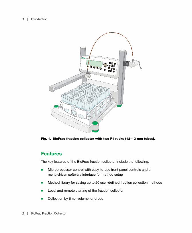
Fig. 1. BioFrac fraction collector with two F1 racks (12–13 mm tubes).
FeaturesThe key features of the BioFrac fraction collector include the following:
Microprocessor control with easy-to-use front panel controls and a
menu-driven software interface for method setup
Method library for saving up to 20 user-defined fraction collection methods
Local and remote starting of the fraction collector
Collection by time, volume, or drops
2 | BioFrac Fraction Collector

Overview
Advanced fraction collection functions. Peak detection, Time, or Volume
windows (up to 20) or a combination of Peak Detection with Time or
Volume windows
Manually adjustable control module that accommodates tube heights up to
150 mm
Compatibility with chromatography systems from Bio-Rad as well as other
manufacturers
Modular system that can be stacked directly on top of the NGC™,
BioLogic DuoFlow™, and BioLogic™ LP chromatography systems
Accommodates several inexpensive, off-the-shelf racks for tubes
(12–20 mm and 30 mm diameter), Eppendorf tubes or microcentrifuge
tubes (0.5 ml, 1.5 ml, and 2 ml) and scintillation vials. Racks are
autoclavable
Ability to collect up to 180 fractions in tubes or 384 fractions in 96-well
microplates
Optional Prep-20 adaptor for preparative collection in up to 20 collection
vessels of any size, from milliliter to liter collection volumes
Optional ice bath (with tube grips) that doubles as a holder for microplates.
Tube grips hold tubes firmly in any position while decanting. Rack allows
cooling of 13 mm tubes on ice. As a microplate holder it accommodates
12-, 24-, 48-, and 96-well microplates and Titertube tubes that adhere to
SBS standards for microplates
Diverter valve to divert flow and minimize spillage during tube changes.
Diverts unwanted eluent to waste and eliminates spills during fraction
advances
Multirun capability for overlaying fractions or collection of experiments
sequentially
Serpentine arm movement. Can be changed to a column or row pattern for
microplates and Titertube tubes
User Guide | 3

1 | Introduction
Optional drop former optimized for small-volume drop dispensing
(recommended when collecting into microplates)
Ability to start/stop an external pump and chart recorder
Screen sleep mode for longer display life
UnpackingWhen unpacking the fraction collector, carefully inspect the containers for any
damage that may have occurred in shipping. Severe damage to a container may
indicate damage to its contents. If you suspect damage to the contents may have
occurred, file a claim immediately with the carrier in accordance with their
instructions before contacting Bio-Rad Laboratories.
Caution: Do not lift the fraction collector by its dispenser arm.
Grip the base of the fraction collector and lift it slowly out of its packing. Do not lift
the unit by its dispenser arm. Remove the remaining contents from each of the
boxes and check all of the parts against the supplied packing list. The BioFrac
fraction collector is shipped with the following:
Fraction collector unit
AC power cord
Fittings kit (Figure 2)
Instruction guide
Tube rack #F1 (2) for 12–13 mm tubes
Diverter valve (including an hex key)
Combicon connector (included with instruction guide)
Note: If any part is missing or damaged, contact Bio-Rad Laboratories
immediately.
4 | BioFrac Fraction Collector

Overview
Fig. 2. Fittings kit.
LEGEND
Item Quantity Contents of Fittings Kit
1 1 1.0 m Tefzel tubing, 1/16" OD, 0.030" ID, with one 1/4-28
fitting
2 4 Fittings, 1/4-28, 1/16" OD
3 4 Ferrules, 1/16" OD
4 2 Unions, luer to 1/4-28
5 1 26” PEEK tubing, 1/16" OD, 0.030" ID, with two 1/4-28
fittings labeled collect HF
6 1 26” PEEK tubing, 1/16" OD, 0.020" ID, with two 1/4-28
fittings labeled collect
User Guide | 5
1 | Introduction
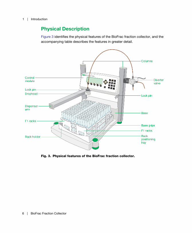
Physical DescriptionFigure 3 identifies the physical features of the BioFrac fraction collector, and the
accompanying table describes the features in greater detail.
Fig. 3. Physical features of the BioFrac fraction collector.
6 | BioFrac Fraction Collector

Overview
Feature Description
Control module The fraction collector head contains the
display, function keys, and alphanumeric
keypad (see Chapter 2, Front and Rear Panel
Controls and Connectors, on page 9). Its
height may be adjusted to accommodate tube
heights up to 150 mm.
Base The fraction collector base holds the rack
positioning tray, power switch, and I/O
connectors. It is designed so that it can be
stacked on top of the NGC, BioLogic DuoFlow,
and BioLogic LP chromatography system
workstations if benchspace is limited.
Columns The columns hold the fraction collector head
and serve as a rack for mounting the diverter
valve or other devices, such as a pH probe and
a UV monitor, using Bio-Rad bar clamps
(Cat. #750-0265).
Rack positioning tray Accurate dispensing requires that racks be
positioned using the rack-positioning tray.
Molded indents on the tray allow the rack feet
to be placed securely on the rack-positioning
tray. The tray holds two full racks (F1, F2, or F3)
on one face and can be inverted for positioning
of four half-racks (H1, H2, H3, or H4). See
Chapter 3, System Configuration and
Plumbing, on page 13 for available rack
options.
Dispenser arm The dispenser arm moves the drophead in a
serpentine motion over each of the collection
tubes. The arm movement can be changed to a
column or row pattern for microplates and
Titertube tubes.
User Guide | 7
1 | Introduction
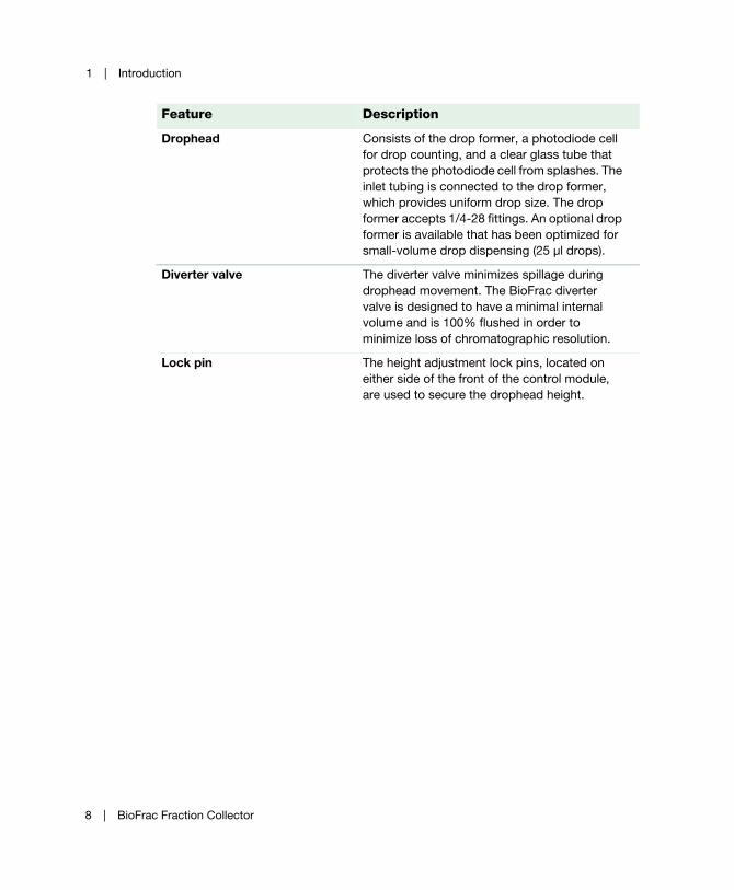
Drophead Consists of the drop former, a photodiode cell
for drop counting, and a clear glass tube that
protects the photodiode cell from splashes. The
inlet tubing is connected to the drop former,
which provides uniform drop size. The drop
former accepts 1/4-28 fittings. An optional drop
former is available that has been optimized for
small-volume drop dispensing (25 µl drops).
Diverter valve The diverter valve minimizes spillage during
drophead movement. The BioFrac diverter
valve is designed to have a minimal internal
volume and is 100% flushed in order to
minimize loss of chromatographic resolution.
Lock pin The height adjustment lock pins, located on
either side of the front of the control module,
are used to secure the drophead height.
Feature Description
8 | BioFrac Fraction Collector
2 Front and Rear Panel Controls and Connectors
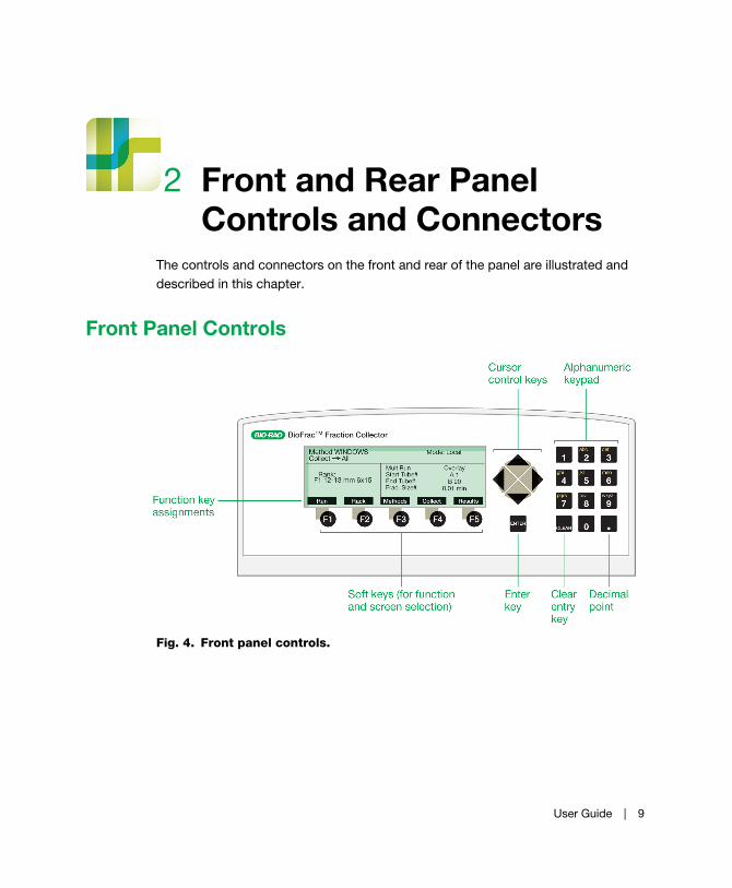
The controls and connectors on the front and rear of the panel are illustrated and
described in this chapter.
Front Panel Controls
Fig. 4. Front panel controls.
User Guide | 9
2 | Front and Rear Panel Controls and Connectors
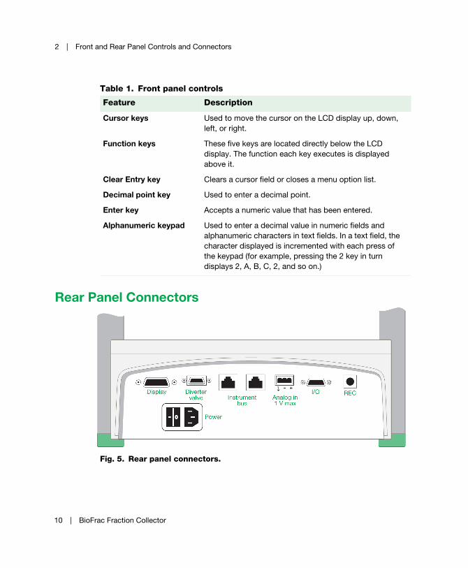
Rear Panel Connectors
Fig. 5. Rear panel connectors.
Table 1. Front panel controls
Feature Description
Cursor keys Used to move the cursor on the LCD display up, down,
left, or right.
Function keys These five keys are located directly below the LCD
display. The function each key executes is displayed
above it.
Clear Entry key Clears a cursor field or closes a menu option list.
Decimal point key Used to enter a decimal point.
Enter key Accepts a numeric value that has been entered.
Alphanumeric keypad Used to enter a decimal value in numeric fields and
alphanumeric characters in text fields. In a text field, the
character displayed is incremented with each press of
the keypad (for example, pressing the 2 key in turn
displays 2, A, B, C, 2, and so on.)
10 | BioFrac Fraction Collector
Rear Panel Connectors
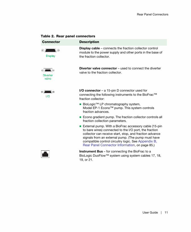
Table 2. Rear panel connectors
Connector Description
Display cable – connects the fraction collector control
module to the power supply and other ports in the base of
the fraction collector.
Diverter valve connector – used to connect the diverter
valve to the fraction collector.
I/O connector – a 15-pin D connector used for
connecting the following instruments to the BioFrac™
fraction collector:
BioLogic™ LP chromatography system,
Model EP-1 Econo™ pump. This system controls
fraction advances.
Econo gradient pump. The fraction collector controls all
fraction collection parameters.
External pump. With a BioFrac accessory cable (15-pin
to bare wires) connected to the I/O port, the fraction
collector can receive start, stop, and fraction advance
signals from an external pump. (The pump must have
compatible control circuitry logic. See Appendix B, Rear Panel Connector Information, on page 85.)
Instrument Bus – for connecting the BioFrac to a
BioLogic DuoFlow™ system using system cables 17, 18,
19, or 21.
User Guide | 11
2 | Front and Rear Panel Controls and Connectors
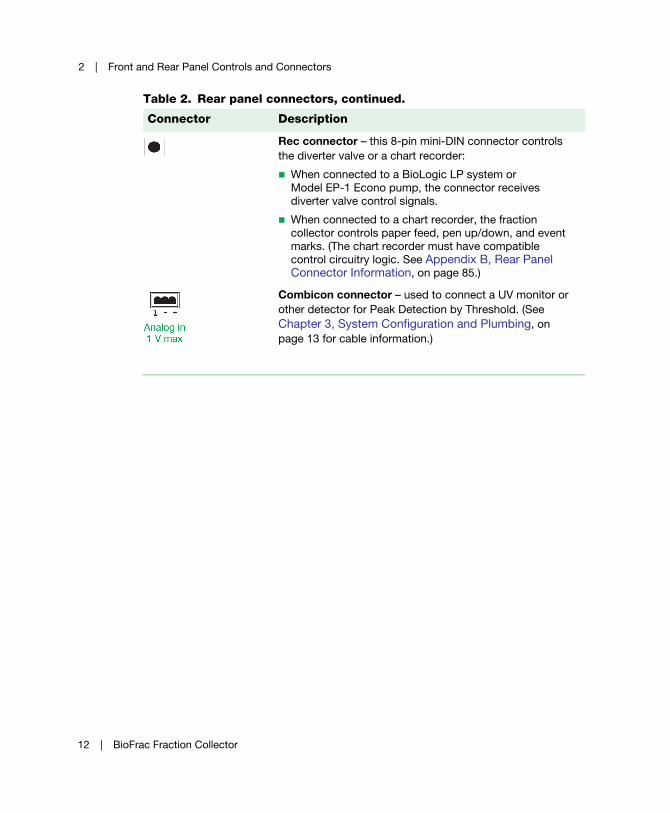
Rec connector – this 8-pin mini-DIN connector controls
the diverter valve or a chart recorder:
When connected to a BioLogic LP system or
Model EP-1 Econo pump, the connector receives
diverter valve control signals.
When connected to a chart recorder, the fraction
collector controls paper feed, pen up/down, and event
marks. (The chart recorder must have compatible
control circuitry logic. See Appendix B, Rear Panel Connector Information, on page 85.)
Combicon connector – used to connect a UV monitor or
other detector for Peak Detection by Threshold. (See
Chapter 3, System Configuration and Plumbing, on
page 13 for cable information.)
Table 2. Rear panel connectors, continued.
Connector Description
12 | BioFrac Fraction Collector
3 System Configuration and Plumbing
The BioFrac™ fraction collector is shipped assembled and requires minimal
plumbing and cabling to prepare it for use. Once assembled, the BioFrac device can
be operated in the following configurations:
BioLogic DuoFlow system control
LP/Econo™ mode collection with Bio-Rad components
Stand-alone fraction collection (Local mode) with Bio-Rad components
Stand-alone fraction collection with components that are not
manufactured by Bio-Rad
The following sections of this chapter describe how to set up the BioFrac fraction
collector and how to connect instruments and devices to work with it.
User Guide | 13
3 | System Configuration and Plumbing
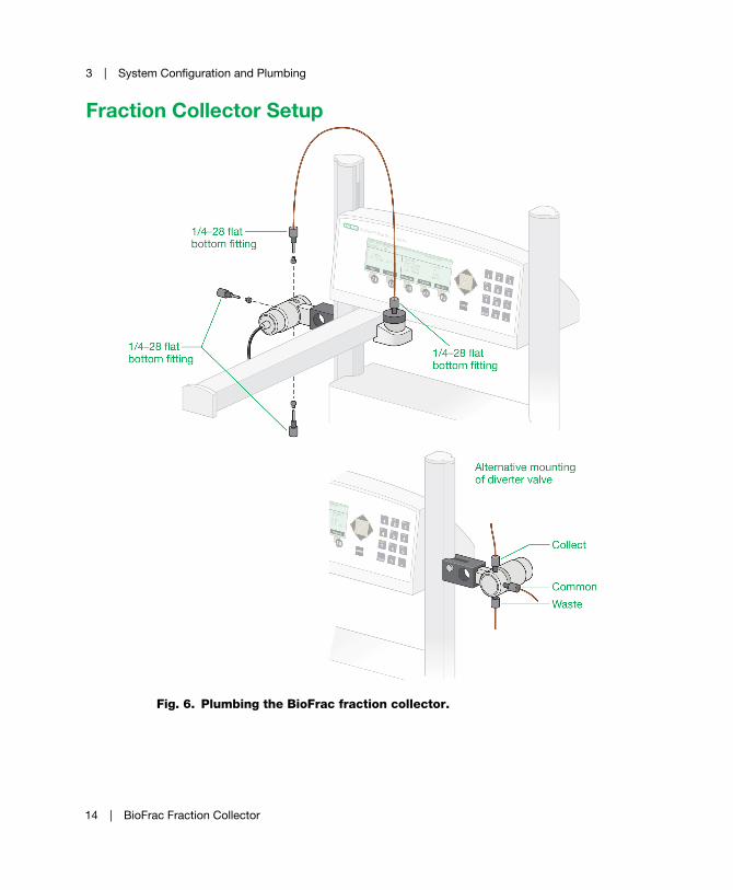
Fraction Collector Setup
Fig. 6. Plumbing the BioFrac fraction collector.
14 | BioFrac Fraction Collector
Fraction Collector Setup
To set up the BioFrac fraction collector
1. Place the fraction collector on a level surface on a laboratory or coldroom
bench or in a cold cabinet. Alternatively, if benchspace is limited, the modular
fraction collector can be stacked on top of the NGC, BioLogic DuoFlow™, or
BioLogic™ LP chromatography system workstations.
2. Connect the fraction collector display cable to the port labeled Display on the
back of the fraction collector. (See Figure 5 on page 10.)
3. Connect the diverter valve cable to the Diverter Valve port on the back of the
fraction collector. (See Figure 5 on page 10.)
4. Attach the diverter valve to either the right or left column. The diverter valve
should be attached so that the Collect port is pointed up and Waste port is
pointing down (see Figure 6 on page 14). Use the included hex key to secure
the diverter valve to the column.
5. Connect all power cords to available grounded, surge-protected outlets.
6. Connect the preassembled 26-inch PEEK 1/16" OD tubing, supplied in the
BioFrac fittings kit, to the Collect port of the diverter valve and to the drophead.
Use the 0.02" ID (orange) tubing for flow rates less than 20 ml/min and the 0.03"
ID (green) tubing for flow rates greater than 20 ml/min.
Note: The diverter valve is rated to a maximum pressure of 30 psi.
If tubing other than that found in the fittings kit is used to plumb the fraction
collector, make sure all tubing lengths are kept to a minimum. This reduces the
delay volume (see Collect Using a Delay Function on page 67) and
backpressure. Tubing choice is dependent on the flow rate and pressure
characteristics of the pumping system. For flow rates above 20 ml/min, use
0.03" ID or 1/8" OD, 0.062" ID tubing (available from most tubing/fitting
suppliers).
7. Attach the 0.03" ID Tefzel tubing, supplied in the fraction collector fittings kit, to
the Waste port of the diverter valve and place the other end into a waste
collection vessel.
Note: If using flow rates greater than 20 ml/min, be sure to use tubing that
has a 0.03" or larger ID.
User Guide | 15
3 | System Configuration and Plumbing
8. Attach the tubing from your chromatography system to the Common port on
the diverter valve using either a 1/4-28 fitting or luer to 1/4-28 union. The
BioFrac fittings kit includes 1/4-28 fittings (for 1/16" OD tubing) and luer to
1/4-28 unions.
9. Connect the fraction collector to your chromatography system as described in
the next section, Connecting Instruments and Devices to the BioFrac Fraction
Collector.
Connecting Instruments and Devices to the BioFrac Fraction Collector
The BioFrac fraction collector can be operated in any of the following
configurations.
BioLogic DuoFlow system control. The system controls the operation of
the fraction collector through the system bus. See Connecting to a
BioLogic DuoFlow Chromatography System on page 17 for details.
LP/Econo mode collection with Bio-Rad components such as the BioLogic
LP system and Model EP-1 Econo™ Pump. The BioLogic LP system
Econo pump controls all aspects of fraction collection.
Stand-alone fraction collection (Local mode) with Bio-Rad components,
such as the Econo gradient pump, a BioLogic QuadTec™ detector, a
Model EM-1 Econo UV monitor, and/or a Model 1327 chart recorder.
Note: The fraction collector provides complete control of fraction
collection.
Stand-alone fraction collection with components that are not
manufactured by Bio-Rad, such as a pump, UV monitor, and/or chart
recorder. In Local mode, the fraction collector provides complete control of
fraction collection and can start/stop an external device such as a pump or
chart recorder. In LP/Econo mode, the controller provides complete control
16 | BioFrac Fraction Collector

Connecting Instruments and Devices to the BioFrac Fraction Collector
of fraction collection. Devices not manufactured by Bio-Rad must be
capable of transistor to transistor logic (TTL) control.
Note: Before proceeding, make sure power to each component to be
connected is turned off. Be sure to use a grounded, surge-protected outlet
when plugging in the power cables.
Connecting to a BioLogic DuoFlow Chromatography SystemConnect the BioFrac fraction collector to the BioLogic DuoFlow system using
system cables 17, 18, 19, or 21.
Fig. 7. Connecting the fraction collector to a BioLogic DuoFlow chromatography
system.
User Guide | 17
3 | System Configuration and Plumbing
To connect the fraction collector to a BioLogic DuoFlow system
1. Connect the bus cable to the connector marked INSTRUMENT BUS on the
base of the fraction collector.
2. Connect the other end of the bus cable to either the INSTRUMENT BUS
connector on the back of the BioLogic DuoFlow workstation or to other
Bio-Rad components that are daisy chained to the BioLogic DuoFlow
workstation by the instrument bus.
3. Place the BioFrac fraction collector in Local mode with the Main screen
displayed (see Main Screen on page 36). Start the BioLogic DuoFlow software
and press System in the manual screen fraction collector dialog box.
Note: The BioFrac fraction collector must be in Local mode and on the
Main screen before the BioLogic DuoFlow system can control it.
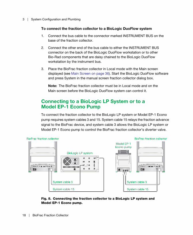
Connecting to a BioLogic LP System or to a Model EP-1 Econo PumpTo connect the fraction collector to the BioLogic LP system or Model EP-1 Econo
pump requires system cables 3 and 15. System cable 15 relays the fraction advance
signal to the BioFrac device, and system cable 3 allows the BioLogic LP system or
Model EP-1 Econo pump to control the BioFrac fraction collector’s diverter valve.
Fig. 8. Connecting the fraction collector to a BioLogic LP system and
Model EP-1 Econo pump.
18 | BioFrac Fraction Collector
Connecting Instruments and Devices to the BioFrac Fraction Collector
To connect the fraction collector to the BioLogic LP system or Model EP-1 Econo pump
1. Connect system cable 15:
a. Connect the cable’s 15-pin D connector to the port labeled I/O on the
fraction collector.
b. Connect the mini-DIN connector to the port labeled Fraction Collector on
the BioLogic LP system or the port labeled on the Model EP-1 Econo
pump.
2. Connect system cable 3:
a. Connect one of the cable’s mini-DIN connectors to the REC port on the
fraction collector.
b. Connect the other mini-DIN connector to the port labeled Diverter Valve on
the BioLogic LP system or the port labeled on the Model EP-1 Econo
pump.
3. If you are connected to a BioLogic LP system, press Collector on the faceplate
and then press the MODEL softkey followed by the BIOFRAC (or 2128) softkey.
4. When prompted to verify that an external valve cable is connected, enter Yes.
5. Follow the procedure, To run the fraction collector in LP/Econo mode on
page 75.
User Guide | 19

3 | System Configuration and Plumbing
Connecting to the Econo Gradient Pump and a Chart RecorderThe following configuration shows the fraction collector set up with an Econo
gradient pump and a chart recorder. This system allows full use of the fraction
collector’s advanced programming features.
Fig. 9. Connecting the fraction collector, Econo gradient pump, and chart
recorder.
To connect the fraction collector, Econo gradient pump, and chart recorder
1. Connect the mini-DIN connector to the I/O connector on the Econo gradient
pump.
2. Connect the 15-pin D-connector to the I/O connector on the fraction collector.
3. If a chart recorder is present, connect the cable’s remaining end to the chart
recorder DIN connector. If the chart recorder is not present, place this portion of
the cable aside.
4. If collecting fractions by threshold, connect a detector to the fraction collector
and chart recorder as described in this chapter.
5. Follow the procedures in Chapter 5, Stand-Alone Operation, on page 57.
20 | BioFrac Fraction Collector
Connecting Instruments and Devices to the BioFrac Fraction Collector
Connecting the Model EP-1 Econo and Econo Gradient PumpsThe BioFrac fraction collector can start an Econo gradient pump or
Model EP-1 Econo pump remotely. To make the necessary connections you will
need a BioFrac accessory cable (catalog # 731-8290) and system cable 7 (catalog #
731-8267).
1. Connect the BioFrac accessory cable green/black and blue/white wires to the
system cable 7 blue wire.
2. Connect the BioFrac accessory cable’s orange/black wire to the system cable 7
yellow wire if you are connecting to an Econo gradient pump, or red wire if you
are connecting to a Model EP-1 Econo pump.
3. Trim off all unused wires.
4. Connect the end of the BioFrac accessory cable with the 15-pin D connector to
the I/O port on the BioFrac fraction collector.
5. Connect the system cable 7 mini-DIN connector to the I/O port on the Econo
gradient pump or Model EP-1 Econo pump.
6. With the fraction collector in Local mode, press Run to start the fraction
collector and pump.
7. If you are collecting by volume, be sure to enter the pump flow rate into the
BioFrac device’s flow rate entry field.
Note: Pressing Stop on the BioFrac fraction collector will not stop the Econo
gradient pump run. The EGP program must be stopped from the Econo
gradient pump faceplate.
Connecting to Components Not Manufactured by Bio-RadThe BioFrac fraction collector is designed to work with a variety of components
from other manufacturers. The BioFrac fraction collector can control remote devices
such as pumps, chart recorders, and UV detectors, and it can accept start/stop
signals from other equipment, such as pumps and UV detectors. The following is a
description of the remote fraction collection control options. To connect the fraction
User Guide | 21
3 | System Configuration and Plumbing
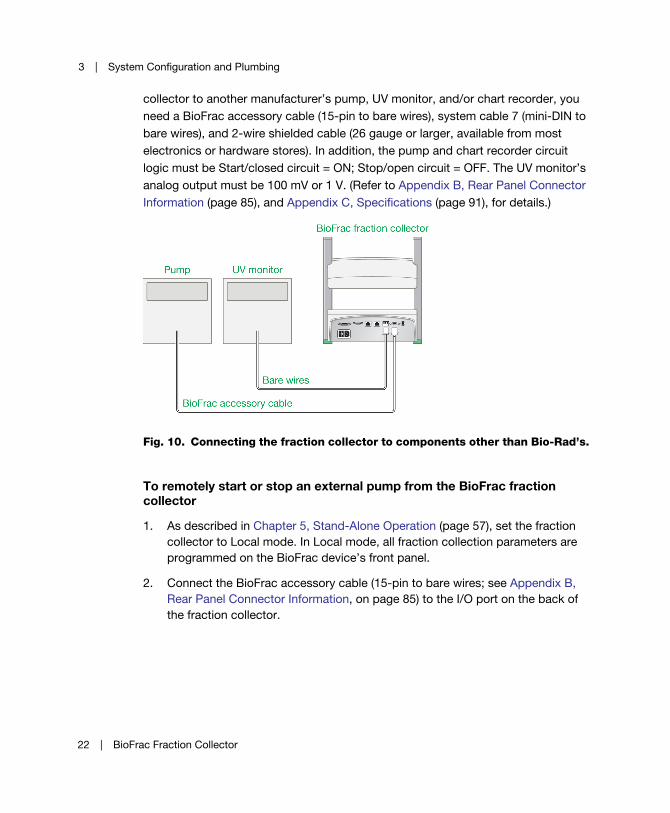
collector to another manufacturer’s pump, UV monitor, and/or chart recorder, you
need a BioFrac accessory cable (15-pin to bare wires), system cable 7 (mini-DIN to
bare wires), and 2-wire shielded cable (26 gauge or larger, available from most
electronics or hardware stores). In addition, the pump and chart recorder circuit
logic must be Start/closed circuit = ON; Stop/open circuit = OFF. The UV monitor’s
analog output must be 100 mV or 1 V. (Refer to Appendix B, Rear Panel Connector
Information (page 85), and Appendix C, Specifications (page 91), for details.)
Fig. 10. Connecting the fraction collector to components other than Bio-Rad’s.
To remotely start or stop an external pump from the BioFrac fraction collector
1. As described in Chapter 5, Stand-Alone Operation (page 57), set the fraction
collector to Local mode. In Local mode, all fraction collection parameters are
programmed on the BioFrac device’s front panel.
2. Connect the BioFrac accessory cable (15-pin to bare wires; see Appendix B,
Rear Panel Connector Information, on page 85) to the I/O port on the back of
the fraction collector.
22 | BioFrac Fraction Collector
Connecting Instruments and Devices to the BioFrac Fraction Collector
3. Connect the BioFrac accessory cable green/black wire (pin #9) to the start pin
on the remote instrument. Refer to your particular pump’s documentation for
further information.
4. Connect the orange/black wire (pin #10) to the remote instrument’s signal
ground. When Run is pressed on the BioFrac instrument, the remote start relay
pins (pins #9 and #10) are connected and the start signal is relayed to the
remote device.
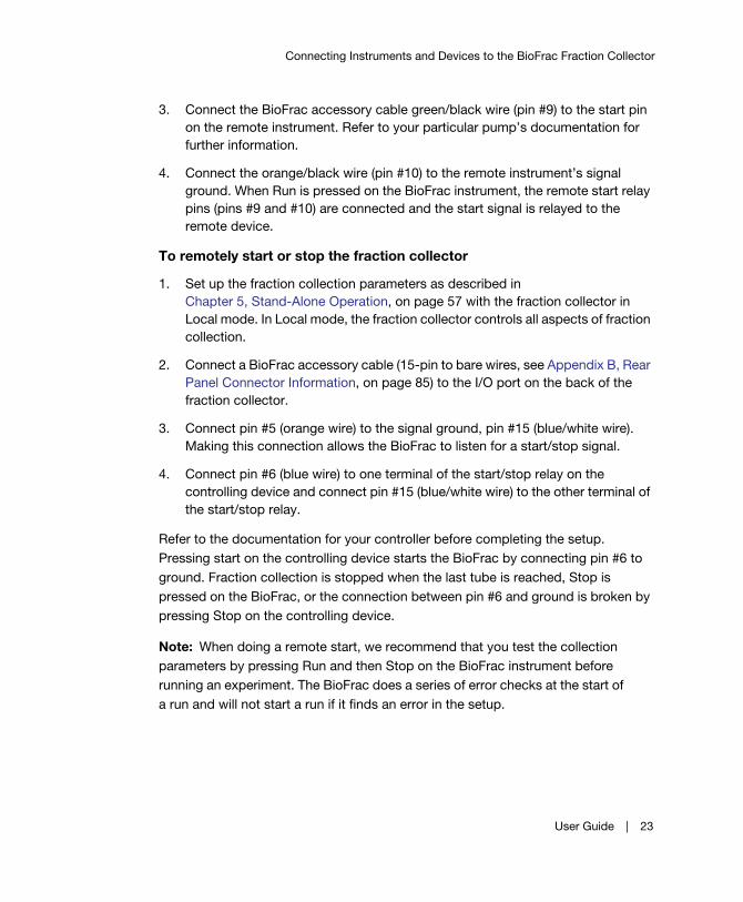
To remotely start or stop the fraction collector
1. Set up the fraction collection parameters as described in
Chapter 5, Stand-Alone Operation, on page 57 with the fraction collector in
Local mode. In Local mode, the fraction collector controls all aspects of fraction
collection.
2. Connect a BioFrac accessory cable (15-pin to bare wires, see Appendix B, Rear
Panel Connector Information, on page 85) to the I/O port on the back of the
fraction collector.
3. Connect pin #5 (orange wire) to the signal ground, pin #15 (blue/white wire).
Making this connection allows the BioFrac to listen for a start/stop signal.
4. Connect pin #6 (blue wire) to one terminal of the start/stop relay on the
controlling device and connect pin #15 (blue/white wire) to the other terminal of
the start/stop relay.
Refer to the documentation for your controller before completing the setup.
Pressing start on the controlling device starts the BioFrac by connecting pin #6 to
ground. Fraction collection is stopped when the last tube is reached, Stop is
pressed on the BioFrac, or the connection between pin #6 and ground is broken by
pressing Stop on the controlling device.
Note: When doing a remote start, we recommend that you test the collection
parameters by pressing Run and then Stop on the BioFrac instrument before
running an experiment. The BioFrac does a series of error checks at the start of
a run and will not start a run if it finds an error in the setup.
User Guide | 23
3 | System Configuration and Plumbing
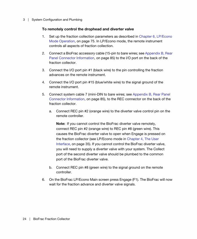
To remotely control the drophead and diverter valve
1. Set up the fraction collection parameters as described in Chapter 6, LP/Econo
Mode Operation, on page 75. In LP/Econo mode, the remote instrument
controls all aspects of fraction collection.
2. Connect a BioFrac accessory cable (15-pin to bare wires; see Appendix B, Rear
Panel Connector Information, on page 85) to the I/O port on the back of the
fraction collector.
3. Connect the I/O port pin #1 (black wire) to the pin controlling the fraction
advances on the remote instrument.
4. Connect the I/O port pin #15 (blue/white wire) to the signal ground of the
remote instrument.
5. Connect system cable 7 (mini-DIN to bare wires; see Appendix B, Rear Panel
Connector Information, on page 85), to the REC connector on the back of the
fraction collector.
a. Connect REC pin #2 (orange wire) to the diverter valve control pin on the
remote controller.
Note: If you cannot control the BioFrac diverter valve remotely,
connect REC pin #2 (orange wire) to REC pin #8 (green wire). This
causes the BioFrac diverter valve to open when Engage is pressed on
the fraction collector (see LP/Econo mode in Chapter 4, The User
Interface, on page 35). If you cannot control the BioFrac diverter valve,
you will need to supply a diverter valve with your system. The Collect
port of the second diverter valve should be plumbed to the common
port of the BioFrac diverter valve.
b. Connect REC pin #8 (green wire) to the signal ground on the remote
controller.
6. On the BioFrac LP/Econo Main screen press Engage (F1). The BioFrac will now
wait for the fraction advance and diverter valve signals.
24 | BioFrac Fraction Collector
Connecting Instruments and Devices to the BioFrac Fraction Collector
Setting Up the Fraction Collector RacksThe BioFrac fraction collector is designed to accommodate a variety of rack
options, including both custom-molded and off-the-shelf racks. Custom racks
include the ice bath/microplate and Prep-20 racks. The top of the ice bath rack
holds microplate (12-, 24-, 48-, and 96-well) and Titertube tube racks that adhere to
Society of Biomolecular Screening (SBS) standards for microplates. Inexpensive
off-the-shelf racks, which accommodate tubes, scintillation vials, and Eppendorf
tubes, can be purchased from Bio-Rad or most scientific product vendors. The rack
options are shown in the next two figures and listed in Table 3.
User Guide | 25

3 | System Configuration and Plumbing
26 | BioFrac Fraction Collector

Connecting Instruments and Devices to the BioFrac Fraction Collector
User Guide | 27

3 | System Configuration and Plumbing
Table 3. BioFrac fraction collector racks
Rack ID
Bio-Rad
Catalog #
Rack Description
Rack
Capacity
Format
Column
x Rows
Tubes
Per Rack
(Total)
F1 741-0010 Holds 12–13 mm diameter
tubes up to 100 mm in height
2 racks 6 x 15 90 (180)
F2 741-0011 Grip rack, holds 15–16 mm
diameter tubes up to 150 mm
in height
2 racks 5 x 12 60 (120)
F3 741-0012 Grip rack, holds 18–20 mm
diameter tubes up to 150 mm
in height
2 racks 4 x 10 40 (80)
H1 741-0013 For 1.5–2.0 ml capless
microtubes
4 racks 6 x 7 42 (168)
H2 741-0014 For 0.5 ml capless
microtubes
4 racks 7 x 9 63 (252)
H3 741-0015 For 16 mm scintillation vials 4 racks 5 x 6 30 (120)
H4 741-0016 For 50 ml conical vials 4 racks 2 x 3 6 (24)
H4-High 741-0020 For 50 ml conical vials 4 racks 2 x 3 6 (24)
Ice bath/
microplate
rack
741-0017 Ice bath for 13 mm diameter
tubes up to 100 mm in
height. This rack also serves
as a holder for 12-, 24-, 48-,
and 96-well microplates and
microtiter tubes that adhere
to the SBS standard format
1 rack 10 x 12 120
P1 224-0096 96-well standard plate 4 plates 96-well 96 (384)
176-6023 96-deep well, 2 ml 4 plates 96-well 96 (384)
P2 48-well microplates 4 plates 48-well 48 (192)
P3 24-well microplates 4 plates 24-well 24 (96)
P4 12-well microplates 4 plates 12-well 12 (48)
TT1 4 racks 96-well 96 (384)
28 | BioFrac Fraction Collector

Connecting Instruments and Devices to the BioFrac Fraction Collector
To prepare the BioFrac fraction collector for fraction collection, set up the unit as
described in the following sections.
Racks F1, F2, and F3
Place the rack positioning tray into the base of the fraction collector, deep side
facing up. Position each rack so that its legs are in the rack guides. Adjust the
fraction collector’s control module appropriately for the height of the tubes being
used. The height adjustment lock pins (see Figure 11 on page 32) can be used to
lock the drophead at the desired height. Tube number 1 is located in the front, left
corner of the each rack.
Racks H1, H2, H3, H4, and H4-High
Place the rack positioning tray into the base of the fraction collector, deep side
facing down. Position each rack so that its legs are in the rack guides. Adjust the
fraction collector control module head appropriately for the height of the tubes
being used. The height adjustment lock pins (see Figure 11 on page 32) can be used
to lock the drophead at the desired height. Tube number 1 is located in the front, left
corner of the each rack. For racks H1 and H2, use only capless microtubes.
Prep-20 741-0018 Preparative rack 1 2 x 10 20 funnels
Bottle For 250 ml bottles 1 4 bottles
Other racks compatible with the BioFrac fraction collector are available from Scienceware
(www.belart.com). Compatible racks include the no-wire and no-wire grip full racks (248 x 105 x
64 mm and 246 x 104 x 64 mm) and half racks (128 x 105 x 43 mm and 128 x 105 x 43 mm) in
formats listed for racks F1–F3 and H1–H4.
Table 3. BioFrac fraction collector racks, continued.
Rack ID
Bio-Rad
Catalog #
Rack Description
Rack
Capacity
Format
Column
x Rows
Tubes
Per Rack
(Total)
User Guide | 29

3 | System Configuration and Plumbing
Ice Bath
Remove the lid of the ice bath/microplate rack and fill the tub approximately ½ full
with crushed ice, replace the lid and insert 13 x 100 mm culture tubes. Remove the
rack positioning tray from the fraction collector and replace it with the ice bath rack.
Adjust the fraction collector control module appropriately for the height of the tubes
being used. The height adjustment lock pins (see Figure 11 on page 32) can be used
to lock the drophead at the desired height. Tube number 1 is located in the front, left
corner of the rack.
Microplates and Titertube Tubes (Racks P1, P2, P3, P4, and TT1)
Remove the rack positioning tray from the fraction collector and replace it with the
ice bath/microplate rack. Position the ice bath/microplate rack such that rack tube
number 1 is in the left, front corner. Mount the plates on the rack using the plate
positioning tabs located on the top of the rack. Adjust the fraction collector control
module appropriately for the height of the plates being used. The height adjustment
lock pins (see Figure 11 on page 32) can be used to lock the drophead at the
desired height. Position the plates such that tube A1 is in the left, front corner. In
order to obtain a uniform fraction size when collecting fractions smaller than 0.5 ml,
we strongly suggest that fraction size be specified in drops rather than time or
volume. Alternatively, the microplate Drop Head Kit (catalog # 741-0088) can be
used to obtain finer resolution of fraction sizes since it delivers an approximately
25 l drop.
Preparative (Prep-20) Adaptor
Attach Tygon tubing to each funnel that is long enough to reach the collection
vessels (20 feet of 3/8" OD, 1/4" ID Tygon tubing is provided for this purpose.)
Ensure that no kinks constrict flow in the tubing. Gravity flow from the prep adaptor
requires that the container used for collection be mounted below the Prep-20
adaptor funnels. A drain trough is provided as added security in the event the tubing
becomes plugged or kinked, preventing sample loss. The drain trough tubing should
be inserted into a clean empty collection vessel.
30 | BioFrac Fraction Collector

Connecting Instruments and Devices to the BioFrac Fraction Collector
To install the Prep-20 adaptor, remove the two green rubber plugs on the left, front
and right, front of the fraction collector. After attaching the Tygon tubing, insert the
Prep-20 adaptor into the preparative rack holder slots. Notice that the drain trough
slopes slightly towards the drain funnel. The collection port tubing extends down the
front of the fraction collector.
Note: The Prep-20 adaptor is rated for use with flow rates up to 100 ml/min.
(For discussion of the plumbing for high flow rates, see Chapter 3, System
Configuration and Plumbing, on page 13.)
Bottles
Place the rack positioning tray, deep side facing up, and place the bottles in the
circles labeled A, B, C, and D. Adjust the fraction collector head appropriately for the
height of the bottles being used.
Adjusting the Drophead Height
The BioFrac fraction collector accommodates collection vessel heights up to 150
mm. Detents, arranged at predefined heights, are positioned along both columns for
added security. The detent positions accommodate all standard tube and
microplate heights. Lock pins fit snugly within the detents to secure the control
module height and prevent the control module from slipping.
User Guide | 31
3 | System Configuration and Plumbing
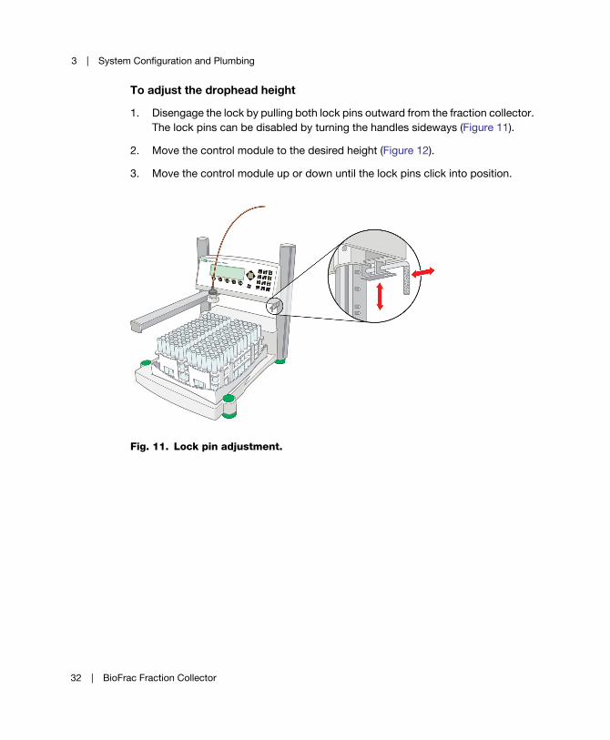
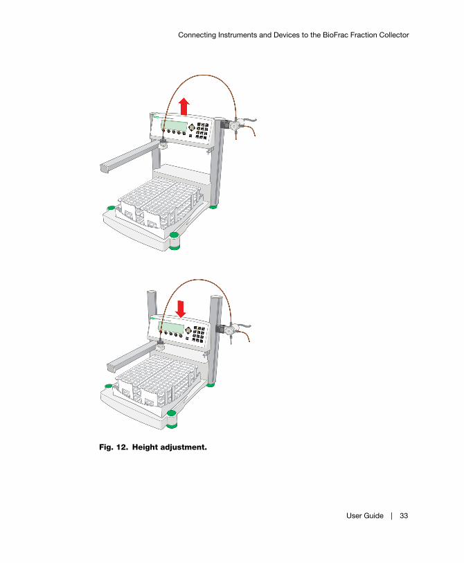
To adjust the drophead height
1. Disengage the lock by pulling both lock pins outward from the fraction collector.
The lock pins can be disabled by turning the handles sideways (Figure 11).
2. Move the control module to the desired height (Figure 12).
3. Move the control module up or down until the lock pins click into position.
Fig. 11. Lock pin adjustment.
32 | BioFrac Fraction Collector
Connecting Instruments and Devices to the BioFrac Fraction Collector
Fig. 12. Height adjustment.
User Guide | 33
3 | System Configuration and Plumbing
34 | BioFrac Fraction Collector
4 The User Interface
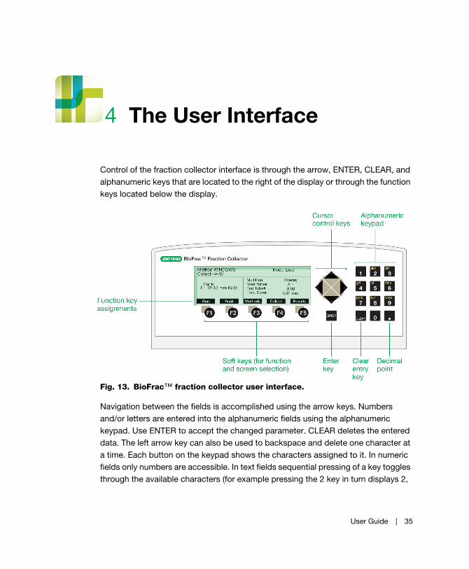
Control of the fraction collector interface is through the arrow, ENTER, CLEAR, and
alphanumeric keys that are located to the right of the display or through the function
keys located below the display.
Fig. 13. BioFrac™ fraction collector user interface.
Navigation between the fields is accomplished using the arrow keys. Numbers
and/or letters are entered into the alphanumeric fields using the alphanumeric
keypad. Use ENTER to accept the changed parameter. CLEAR deletes the entered
data. The left arrow key can also be used to backspace and delete one character at
a time. Each button on the keypad shows the characters assigned to it. In numeric
fields only numbers are accessible. In text fields sequential pressing of a key toggles
through the available characters (for example pressing the 2 key in turn displays 2,
User Guide | 35

4 | The User Interface
A, B, C, 2, and so on). The five function keys are used to move between different
screens or perform predefined functions. When the cursor is in a menu selection
field, pressing ENTER causes the menu to be displayed. Once a menu is displayed,
the up/down arrow keys are used to navigate through the menu items. Pressing
ENTER selects the menu item shown at the cursor position.
Main Screen
The Main screen provides information about the operation mode (Local or
LP/Econo), method name, rack, and fraction collection parameters. The parameter
fields displayed depend on whether the fraction collector is in Local mode (see
Figure 14, Table 4, and Table 5) or LP/Econo mode (see Figure 15, Table 6, and
Table 7).
Main Screen (Local Mode)In Local mode, the Main screen is used to set the multirun mode, start and end tube
numbers, fraction size, fraction size units, and flow rate (see Figure 14, Table 4, and
Table 5). Function keys are used to start a run (see Local Mode) or switch to the
Rack, Method Library, Advanced Collection, and Results screens.
Fig. 14. Main screen (Local mode).
36 | BioFrac Fraction Collector

Main Screen
Table 4. Main screen parameters (Local mode)
Parameter Function
Method Displays the current method name (text only).
Collect Displays the currently selected collection mode: All, Threshold,
Windows, Windows/Threshold (text only).
Rack Displays the currently selected rack (text only).
MultiRun Menu for choosing the multiple run function:
Overlay – causes collection to occur in the same tubes for each
subsequent experiment. In this mode the initial end tube should
be equal to or greater than the number of tubes required for
each experiment.
Seq. Tube+1 – increments the start and end tube numbers at
the end of each run so that one tube is skipped between runs.
In this mode the initial end tube should be set to reflect the
number of tubes required for each experiment rather than the
number of tubes in the rack. If the incremented start or end
tube number exceeds the rack’s tube capacity, a message
appears stating that there are not enough tubes for the next
run.
Seq. Rack – increments the start and end tube numbers at the
end of each run so that each run starts at a different rack. In this
mode, the initial end tube should be set to reflect the number of
tubes required for each experiment rather than the total number
of tubes available. If the incremented start or end tube number
exceeds the rack’s tube capacity, a message appears stating
that there are not enough tubes for the next run.
Start Tube #
End Tube #
Used to set the start tube and end tube. A, B, C, and D
correspond to the specific rack position and the associated
number corresponds to the tube position within each rack. Start
tube and end tube are automatically updated at the end of an
experiment if MultiRun is set to Seq. Tube+1 or Seq. Rack.
Frac. Size Defines the current fraction size in time (min), volume (ml), or
drops.
User Guide | 37
4 | The User Interface
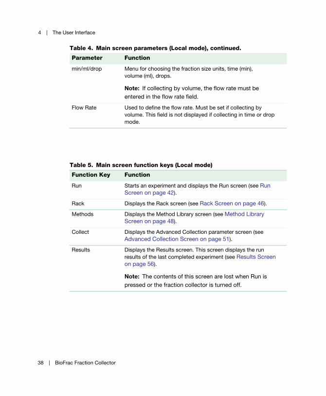
min/ml/drop Menu for choosing the fraction size units, time (min),
volume (ml), drops.
Note: If collecting by volume, the flow rate must be
entered in the flow rate field.
Flow Rate Used to define the flow rate. Must be set if collecting by
volume. This field is not displayed if collecting in time or drop
mode.
Table 5. Main screen function keys (Local mode)
Function Key Function
Run Starts an experiment and displays the Run screen (see Run
Screen on page 42).
Rack Displays the Rack screen (see Rack Screen on page 46).
Methods Displays the Method Library screen (see Method Library
Screen on page 48).
Collect Displays the Advanced Collection parameter screen (see
Advanced Collection Screen on page 51).
Results Displays the Results screen. This screen displays the run
results of the last completed experiment (see Results Screen
on page 56).
Note: The contents of this screen are lost when Run is
pressed or the fraction collector is turned off.
Table 4. Main screen parameters (Local mode), continued.
Parameter Function
38 | BioFrac Fraction Collector
Main Screen
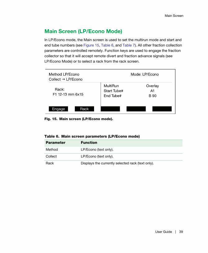
Main Screen (LP/Econo Mode)In LP/Econo mode, the Main screen is used to set the multirun mode and start and
end tube numbers (see Figure 15, Table 6, and Table 7). All other fraction collection
parameters are controlled remotely. Function keys are used to engage the fraction
collector so that it will accept remote divert and fraction advance signals (see
LP/Econo Mode) or to select a rack from the rack screen.
Fig. 15. Main screen (LP/Econo mode).
Table 6. Main screen parameters (LP/Econo mode)
Parameter Function
Method LP/Econo (text only).
Collect LP/Econo (text only).
Rack Displays the currently selected rack (text only).
User Guide | 39
4 | The User Interface
MultiRun Menu for choosing the multiple run function:
Overlay – causes collection to occur in the same tubes for
each subsequent experiment. In this mode, the fraction
collector moves back to the start tube when the end tube is
filled. Stop is used to disengage the experiment.
Seq. Tube+1 – increments the start and end tube numbers at
the end of each run so that one tube is skipped between runs.
In this mode, the initial end tube should be set to reflect the
number of tubes required for each experiment rather than the
number of tubes in the rack. If the incremented start or end
tube number exceeds the rack’s tube capacity, a message
appears stating that there are not enough tubes for the next
run. The start tube and end tube are incremented each time
the fraction collector is disengaged by pressing stop or by
filling the end tube.
Seq. Rack – increments the start and end tube numbers at the
end of each run so that each run starts on a different rack. In
this mode, the initial end tube should be set to reflect the
number of tubes required for each experiment rather than the
total number of tubes available. If the incremented start or end
tube number exceeds the rack’s tube capacity, a message
appears stating that there are not enough tubes for the next
run. The start tube and end tube are incremented each time
the fraction collector is disengaged by pressing stop or by
filling the end tube.
Start Tube #
End Tube #
Used to set the start and end tube. A, B, C, and D correspond
to the rack position. The associated number corresponds to
the tube position within each rack. Start tube and end tube are
automatically updated at the end of an experiment if MultiRun
is Seq. Tube+1 or Seq. Rack.
Table 6. Main screen parameters (LP/Econo mode), continued.
Parameter Function
40 | BioFrac Fraction Collector
Main Screen
Table 7. Main screen function keys (LP/Econo mode)
Function Key Function
Engage Moves the drophead to the start tube and causes the fraction
collector to listen for fraction advance and diverter valve
signals.
Rack Displays the Rack Selection screen.
User Guide | 41
4 | The User Interface
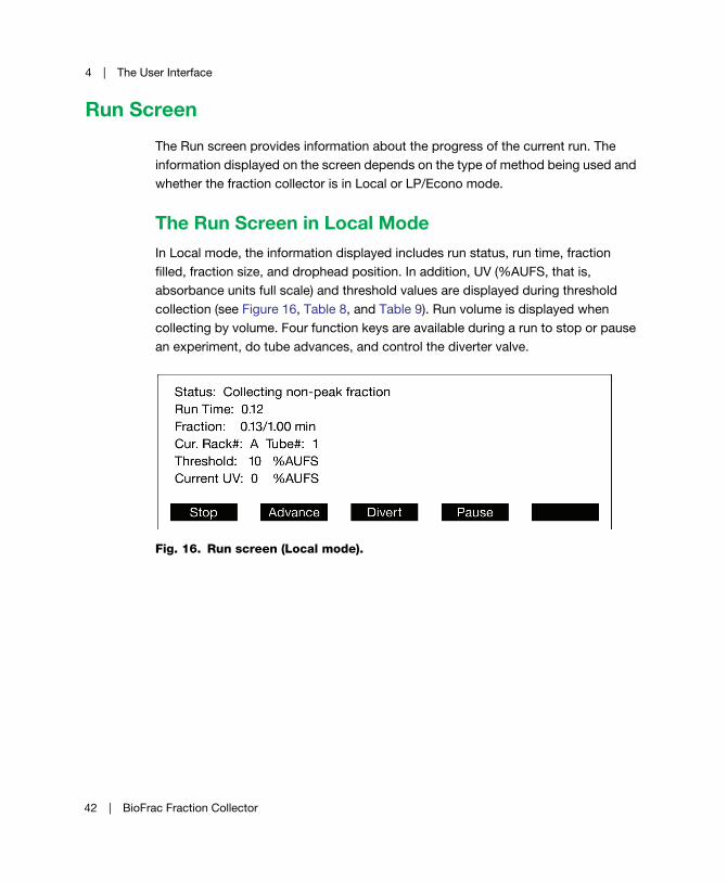
Run Screen
The Run screen provides information about the progress of the current run. The
information displayed on the screen depends on the type of method being used and
whether the fraction collector is in Local or LP/Econo mode.
The Run Screen in Local ModeIn Local mode, the information displayed includes run status, run time, fraction
filled, fraction size, and drophead position. In addition, UV (%AUFS, that is,
absorbance units full scale) and threshold values are displayed during threshold
collection (see Figure 16, Table 8, and Table 9). Run volume is displayed when
collecting by volume. Four function keys are available during a run to stop or pause
an experiment, do tube advances, and control the diverter valve.
Fig. 16. Run screen (Local mode).
42 | BioFrac Fraction Collector

Run Screen
Table 8. Run screen parameters (Local mode)
Parameter Function
Status Displays the current fraction collection status:
Collecting – the diverter valve is in the collect
position and fractions of a user-specified size
are being collected.
Diverting – the diverter valve is in the Waste
position. Run Paused!: The run is currently
paused and the diverter valve is at Waste. A
warning is displayed that the diverter valve is
diverting to Waste.
Collecting Non-Peak – the diverter valve is in
the collect position but is collecting fractions
of non-peak size.
Will Collect at End of Delay – the fraction
collector is waiting for the delay time before
it switches the diverter valve to Collect.
Will Divert at End of Delay – the fraction
collector is waiting for the delay time before
it switches the diverter valve to Waste.
Run Time Displays the current run time (in hours and
minutes). Stops incrementing during a pause. If
collecting by volume, the run volume is also
displayed.
Cur. Rack # Tube # Displays the current rack position and tube
number.
Threshold Displays the current threshold setting as a
percentage of full scale (%AUFS). (Displayed
only if collecting by threshold).
Current UV Displays the current UV signal value as a
percentage of full scale (%AUFS). (Displayed
only if collecting by threshold).
User Guide | 43

4 | The User Interface
Table 9. Run screen function keys (Local mode)
Function Key Function
Stop Stops the current experiment and displays the
Results screen.
Advance Advances the drophead by one tube.
Divert/Collect Toggles the diverter valve between Collect and
Waste.
Pause Pauses fraction collection and switches the
diverter valve to Waste during the pause.
Resume Resumes fraction collection after a pause.
44 | BioFrac Fraction Collector
Run Screen
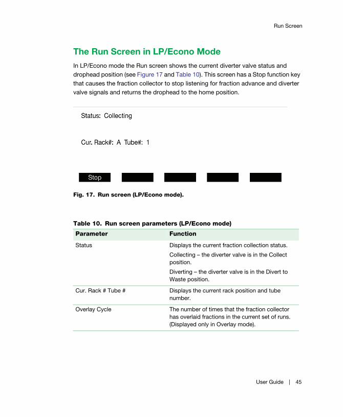
The Run Screen in LP/Econo ModeIn LP/Econo mode the Run screen shows the current diverter valve status and
drophead position (see Figure 17 and Table 10). This screen has a Stop function key
that causes the fraction collector to stop listening for fraction advance and diverter
valve signals and returns the drophead to the home position.
Fig. 17. Run screen (LP/Econo mode).
Table 10. Run screen parameters (LP/Econo mode)
Parameter Function
Status Displays the current fraction collection status.
Collecting – the diverter valve is in the Collect
position.
Diverting – the diverter valve is in the Divert to
Waste position.
Cur. Rack # Tube # Displays the current rack position and tube
number.
Overlay Cycle The number of times that the fraction collector
has overlaid fractions in the current set of runs.
(Displayed only in Overlay mode).
User Guide | 45

4 | The User Interface
Rack Screen
The Rack screen is used to select the rack type and collection pattern to be used in
a method (see Figure 18, Table 11, and Table 12). The default collection pattern is
serpentine; however, it may be changed to collection by row or by column when
collecting in microplates or Titertube tubes. The Divert Between Tubes feature can
be used to reduce the amount of liquid spilled during tube advances. When this
option is turned on (default), the diverter valve switches to waste during tube
advances. However, if this option is turned off (recommended when collecting in
drop mode at low flow rates), the diverter valve switches to Waste only when the
drophead is moving between nonadjacent tubes.
Fig. 18. Rack screen.
Table 11. Rack screen parameters
Parameter Function
Current Rack Menu used for rack selection.
Divert Between Tubes Allows the user to turn off the Divert Between
Tubes function. The fraction collector still
diverts when the drophead is moving between
nonadjacent tubes.
Collection Pattern Displays the current fraction collection pattern.
This pattern can be changed to row or column
for microplates and Titertube tubes.
46 | BioFrac Fraction Collector
Rack Screen
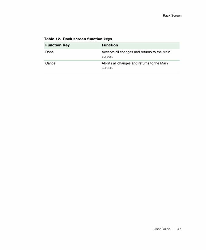
Table 12. Rack screen function keys
Function Key Function
Done Accepts all changes and returns to the Main
screen.
Cancel Aborts all changes and returns to the Main
screen.
User Guide | 47
4 | The User Interface
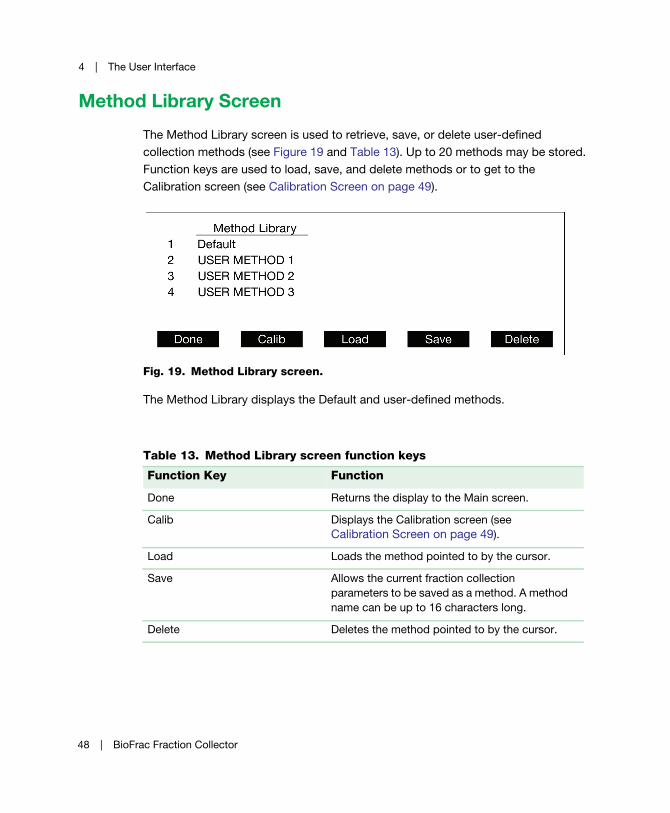
Method Library Screen
The Method Library screen is used to retrieve, save, or delete user-defined
collection methods (see Figure 19 and Table 13). Up to 20 methods may be stored.
Function keys are used to load, save, and delete methods or to get to the
Calibration screen (see Calibration Screen on page 49).
Fig. 19. Method Library screen.
The Method Library displays the Default and user-defined methods.
Table 13. Method Library screen function keys
Function Key Function
Done Returns the display to the Main screen.
Calib Displays the Calibration screen (see
Calibration Screen on page 49).
Load Loads the method pointed to by the cursor.
Save Allows the current fraction collection
parameters to be saved as a method. A method
name can be up to 16 characters long.
Delete Deletes the method pointed to by the cursor.
48 | BioFrac Fraction Collector

Calibration Screen
Calibration Screen
Use the Calibration screen to adjust the drophead calibration, screen contrast, sleep
mode, and to zero the analog-to-digital converter (AtoD). Refer to Table 14 for more
information about the use of each function key.
Table 14. Calibration screen function keys
Function Key Function
Done Returns the display to the Method Library
screen.
Contrst Allows the user to set the display contrast. The
up and down arrow keys are used to increase
and decrease the screen brightness,
respectively.
X–Y axis Places the fraction collector in rack calibration
mode. Allows the user to calibrate the fraction
collector X–Y arm. Calibration should rarely be
required. Calibration is done on an F1 rack that
has 13 x 100 mm glass tubes in positions A1,
A15, and B90 (plastic tubes should not be
used). See Calibrating the Fraction Collector
X–Y Arm on page 50.
Caution: Using this function overwrites
the previous calibration.
Zero AD Allows the user to zero any voltage offset in the
analog-to-digital (AtoD) converter. The AtoD is
used to convert the analog UV signal used for
threshold collection to a digital signal. In the
event of an offset in the AtoD voltage, the
Current UV signal (see Figure 16) displayed on
the run screen may be in error. This calibration
should rarely be required.
To zero the AtoD, press Zero AD, connect a
shorting plug (Combicon connector with the
analog IN(+) and IN(–) pins connected to the
analog IN (ground)), then press Next.
User Guide | 49

4 | The User Interface
Calibrating the Fraction Collector X–Y Arm
To calibrate the Fraction Collector X–Y arm
Caution: Using this function overwrites the previous calibration.
1. Remove the drop former top by twisting it counterclockwise and gently lifting it
out.
2. Press X–Y Axis and then Next.
3. While looking through the drophead, center it over tube A15 using the arrow
keys, and press Next.
4. Center the drophead over tube A1 using the arrow keys, press Next.
5. Center the drophead over tube B90 using the arrow keys, press Save.
6. Replace the top of the drop former by inserting it into the drophead and twisting
it clockwise.
Sleep Allows the user to select how many minutes the
display should wait before going into sleep
mode. Pressing any button will wake up the
display.
Table 14. Calibration screen function keys, continued.
Function Key Function
50 | BioFrac Fraction Collector

Advanced Collection Screen
Advanced Collection Screen
The Advanced Collection screen is used to turn threshold and windows collection
on or off and to set threshold and delay parameters (see Figure 20, Table 15, and
Table 16). Threshold parameters are displayed only when threshold is turned on.
From this screen, the threshold level and UV detector input voltage (100 mV or 1 V)
can be entered and the user can specify whether non-peak fractions are to be
collected or not. A bubble filter time constant can also be entered. During threshold
collection the bubble filter function suppresses unwanted fraction advances due to
air bubbles passing through the UV detector. See Appendix A, Bubble Filter Time,
on page 83, for more information about the bubble filter function.
When windows collection is turned on, the Table function key, F3, is used to display
the Collection Windows Table screen (see Collection Windows Table Screen on
page 54). The Collection Windows Table screen is used to enter all collection
windows parameters. If you are collecting by threshold and windows, turn on
threshold before entering the Collection Windows Table screen.
Fig. 20. Advanced Collection screen.
Table 15. Advanced Collection screen parameters
Parameter Function
Windows Menu for turning Collection by Windows on or off.
Threshold Menu for turning Collection by Threshold on or off.
User Guide | 51

4 | The User Interface
%AUFS Current threshold setting. (Displayed only when Threshold is
on).
Full Scale Menu for defining the UV detector’s output voltage.
(Displayed only if Threshold is on.) The detector input
voltage can be set to either 100 mV or 1 V.
NonPeak Frac. Turns collection of non-peak fractions on or off. (Displayed
only if Threshold is on).
Size The non-peak fraction size. The non-peak fraction size has
the same units as the fraction size and delay parameters.
(Displayed only when Threshold is on).
Bubble Filter Time constant entered in seconds, used to filter false peaks
above a threshold due to electrical noise or air bubbles.
Typically a bubble filter time of 0 or 1 sec will suffice. For a
discussion of bubble filter time, refer to Appendix A,
Bubble Filter Time, on page 83. (Displayed only when
Threshold is on).
Delay A delay time used to precisely synchronize the UV signal
with event marks on the chart recorder and tube advances.
Delay must be less than or equal to the fraction size.
Note: Using delay will result in a timing offset between tube
advances and the displayed fraction fill volume shown on
the Run screen. Delay has the same units as the fraction
size parameter. For a discussion of the delay function, see
Collect Using a Delay Function on page 67.
Table 15. Advanced Collection screen parameters, continued.
Parameter Function
52 | BioFrac Fraction Collector
Advanced Collection Screen
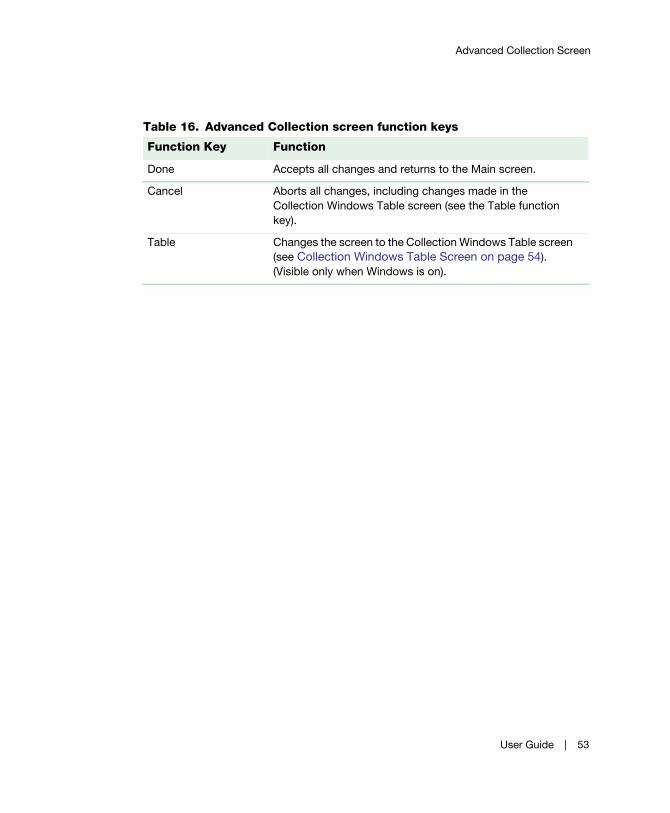
Table 16. Advanced Collection screen function keys
Function Key Function
Done Accepts all changes and returns to the Main screen.
Cancel Aborts all changes, including changes made in the
Collection Windows Table screen (see the Table function
key).
Table Changes the screen to the Collection Windows Table screen
(see Collection Windows Table Screen on page 54).
(Visible only when Windows is on).
User Guide | 53
4 | The User Interface
Collection Windows Table Screen
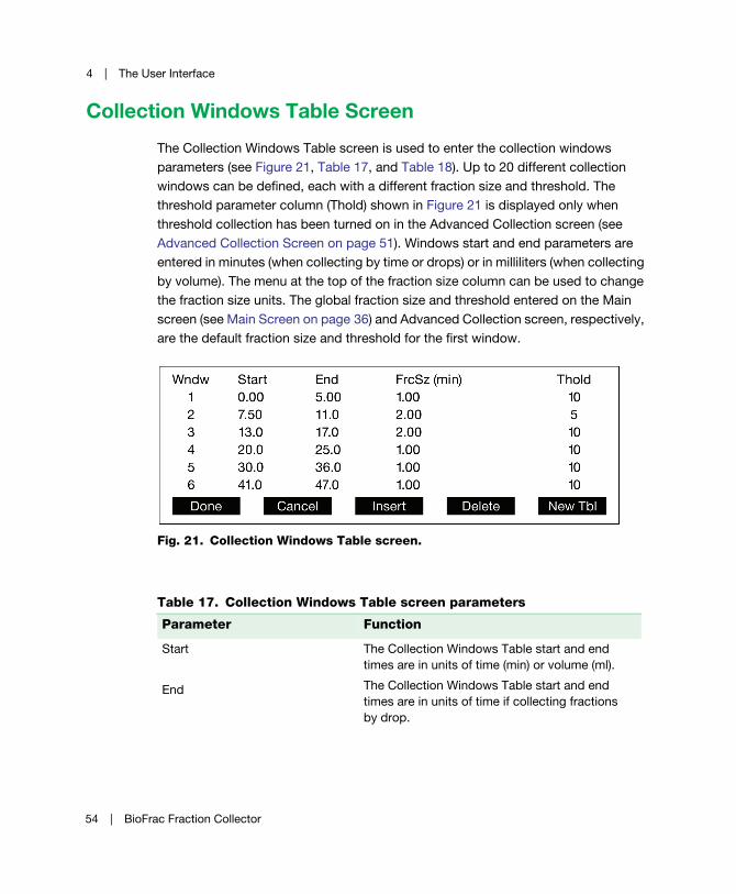
The Collection Windows Table screen is used to enter the collection windows
parameters (see Figure 21, Table 17, and Table 18). Up to 20 different collection
windows can be defined, each with a different fraction size and threshold. The
threshold parameter column (Thold) shown in Figure 21 is displayed only when
threshold collection has been turned on in the Advanced Collection screen (see
Advanced Collection Screen on page 51). Windows start and end parameters are
entered in minutes (when collecting by time or drops) or in milliliters (when collecting
by volume). The menu at the top of the fraction size column can be used to change
the fraction size units. The global fraction size and threshold entered on the Main
screen (see Main Screen on page 36) and Advanced Collection screen, respectively,
are the default fraction size and threshold for the first window.
Fig. 21. Collection Windows Table screen.
Table 17. Collection Windows Table screen parameters
Parameter Function
Start
End
The Collection Windows Table start and end
times are in units of time (min) or volume (ml).
The Collection Windows Table start and end
times are in units of time if collecting fractions
by drop.
54 | BioFrac Fraction Collector

Collection Windows Table Screen
FrcSz The fraction size for the current window (min,
ml, drops). The header for this column is also a
menu that can be used to change the fraction
size units to min, ml, or drops.
Thold The threshold value for each collection window.
Table 18. Collection Windows Table Screen function keys
Function Key Function
Done Saves any changes, contingent upon pressing
Done on the Advanced Collection screen, and
exits the Collection Windows Table screen.
Cancel Aborts all changes and returns to the Advanced
Collection screen.
Insert Inserts a new window at the position pointed to
by the cursor.
Caution: If 20 windows are defined, pressing
Insert causes window #20 to be deleted.
Delete Deletes a window at the position pointed to by
the cursor.
New Deletes all windows.
Table 17. Collection Windows Table screen parameters, continued.
Parameter Function
User Guide | 55

4 | The User Interface
Results Screen
The Results screen provides a list of the tubes associated with each peak or
window. When collecting by threshold, a peak is defined as the tubes collected
while the UV signal was above threshold. The Results screen is displayed at the end
of each run, if the run was not started remotely, or can be viewed by pressing F5 on
the Main screen (see Main Screen on page 36). The information on this screen is lost
when a new run is started or the fraction collector is turned off.
Fig. 22. Results screen.
The Done key returns you to the Main screen.
Table 19. Results screen parameters
Parameter Function
Window/Peak If collecting by Windows, the window number is displayed.
If collecting by Threshold or by Windows and Threshold,
the peak number is displayed.
Tubes List of the tubes associated with each window or peak.
56 | BioFrac Fraction Collector

5 Stand-Alone Operation
Normal operation of the BioFrac™ fraction collector is in Local mode (stand-alone
mode). As a stand-alone fraction collector, the BioFrac device may be used to
collect fractions based on time (minutes), volume (milliliters), or drops (up to a flow
rate of 5.0 ml/min). In Local mode, the fraction collector controls all aspects of
fraction collection and is not in communication with Bio-Rad’s BioLogic DuoFlow™
chromatography system, BioLogic™ LP system, or Model EP-1 Econo™ pump.
However, it may be connected to separate components, such as a UV monitor, a
chart recorder, and a pump, as described in Connecting Instruments and Devices to
the BioFrac Fraction Collector on page 16.
There are four modes of collection, each of which can include a delay function:
Collect All — enables you to collect an entire run without diverting any
fluid to waste.
Peak Detection by Threshold — enables you to collect peaks by defining
a threshold value (percent of full scale) above which fractions will be
collected. This method can be used only when the fraction collector is
connected to a UV monitor. When the UV signal is less than the threshold,
fluid is diverted to waste. Alternatively, it may be collected in tubes with a
non-peak fraction size. A slope function is built into the threshold function
so that double peaks above the set threshold level are detected and
collected separately.
Note: False peaks above a threshold (such as electrical noise or air
bubbles) may be filtered using the bubble filter time function. See Appendix
A, Bubble Filter Time, on page 83.
User Guide | 57
5 | Stand-Alone Operation
Windows Collection — enables you to specify periods of time or volumes
(windows) during which fractions are to be collected. For example, a
window can be defined to start after an initial void volume. The BioFrac
fraction collector lets you define up to 20 different time or volume windows.
The liquid delivered during a collection window is collected into tubes,
whereas the liquid delivered outside of a collection window is diverted to
waste.
Peak Detection by Threshold with Time or Volume Windows — enables
you to combine the Peak Detection by Threshold and the Time or Volume
Windows methods discussed above. This method can be used only when
the fraction collector is connected to a UV monitor. You can program up to
20 different time or volume windows, each with its own threshold level.
This is a useful feature to compensate for baseline drift.
Note: False peaks above a threshold (such as electrical noise or air
bubbles) may be filtered using the bubble filter time function. See Appendix
A, Bubble Filter Time, on page 83.
Delay Function — the purpose of the delay function is to synchronize the
fraction collection event marks and the signal from the UV monitor (output
on a chart recorder) with the actual delivery of liquid into collection tubes.
This features allows easy post-run analysis of a chromatogram. The delay
function is slightly different for each of the collection modes: All, Threshold,
Windows, and Threshold with Windows. As a consequence, the event
marks on the chart recorder will vary depending on the individual
application.
Regardless of the type of collection method programmed, the method will end once
the end tube number is reached. Always ensure that the start and end tube numbers
are set to allow completion of your collection method.
58 | BioFrac Fraction Collector

Collect All
Collect All
Fig. 23. Running a Collect All method.
To run a Collect All method
1. On the Main screen, ensure that Collect is set to Collect –> All. If the screen is
not set to Collect –> All, press Collect (F4) and turn Windows and Threshold off.
Alternatively, press Method (F3) and load the method Default.
2. To select a rack, press Rack (F2) and choose a rack from the Rack menu.
Choose whether you want the diverter valve to divert to waste during fraction
advances. If you are collecting in microplates or Titertube tubes, choose a
collection pattern: Serpentine, Row, or Column.
Note: Whenever a new rack is selected, the start tube and end tube
values are updated to reflect the maximum number of tubes available for
the selected rack.
3. Choose the appropriate MultiRun mode for your experiment (see Table 4 on
page 37 for a description of the MultiRun function).
4. Set the start tube and end tube rack position and tube number.
User Guide | 59
5 | Stand-Alone Operation
The fraction collector stops when the last tube is reached unless a stop
command is received before it reaches the last tube. At the end of a run, the
start tube number and end tube number will be automatically updated
according to the MultiRun mode selected.
5. Set the fraction size units (min, ml, or drops) and enter the fraction size. If
collecting by volume, you must enter a flow rate.
6. (Optional) Press Collect (F4) and set the delay time (see Collect Using a Delay
Function on page 67).
7. (Optional) Press Methods (F3) and save your method.
8. Press Run (F1) to start the experiment.
At any point during the run you can use the Run screen function keys (see
Table 8 on page 43).
60 | BioFrac Fraction Collector
Peak Detection by Threshold
Peak Detection by Threshold
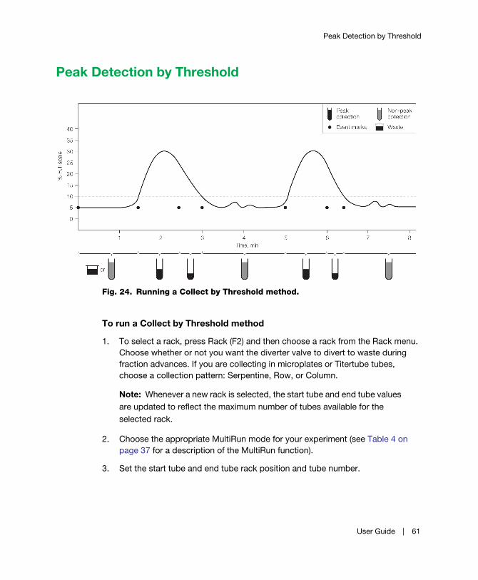
Fig. 24. Running a Collect by Threshold method.
To run a Collect by Threshold method
1. To select a rack, press Rack (F2) and then choose a rack from the Rack menu.
Choose whether or not you want the diverter valve to divert to waste during
fraction advances. If you are collecting in microplates or Titertube tubes,
choose a collection pattern: Serpentine, Row, or Column.
Note: Whenever a new rack is selected, the start tube and end tube values
are updated to reflect the maximum number of tubes available for the
selected rack.
2. Choose the appropriate MultiRun mode for your experiment (see Table 4 on
page 37 for a description of the MultiRun function).
3. Set the start tube and end tube rack position and tube number.
User Guide | 61

5 | Stand-Alone Operation
The fraction collector stops when the last tube is reached unless a stop
command is received before it reaches the last tube. At the end of a run, the
start tube number and end tube number are automatically updated according
to the MultiRun mode selected.
4. Set the fraction size units (min, ml, drops) and set the fraction size. If collecting
by volume, you must enter a flow rate.
5. Press Collect (F4) and turn Threshold on. Set the global %AUFS and set the
detector input voltage to either 100 mV or 1 V full scale depending on your
detector’s output voltage. Press Done. On the Main screen, Collect should now
read Collect –> Threshold.
6. For collection of non-peak fractions, change NonPeak Frac. from Divert to
Collect and enter a size for the non-peak fractions.
7. (Optional) Set the bubble filter time. This function detects and filters false peaks
(such as electrical noise or air bubbles). Typically, a bubble filter time of 0 or 1
sec will suffice. (For a discussion of the bubble filter time function, see
Appendix A, Bubble Filter Time, on page 83.)
8. (Optional) Press Collect (F4) and set the delay time.
9. (Optional) press Method (F3) and save your method.
10. Press Run (F1) to start the experiment.
At any point during the run you may use the Run screen function keys (see
Table 8 on page 43).
62 | BioFrac Fraction Collector
Collect by Windows
Collect by Windows
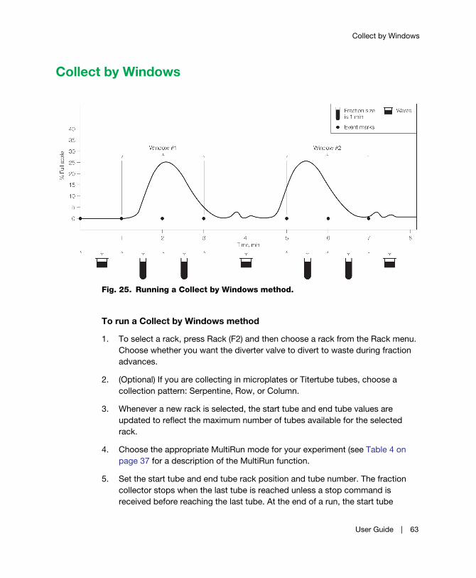
Fig. 25. Running a Collect by Windows method.
To run a Collect by Windows method
1. To select a rack, press Rack (F2) and then choose a rack from the Rack menu.
Choose whether you want the diverter valve to divert to waste during fraction
advances.
2. (Optional) If you are collecting in microplates or Titertube tubes, choose a
collection pattern: Serpentine, Row, or Column.
3. Whenever a new rack is selected, the start tube and end tube values are
updated to reflect the maximum number of tubes available for the selected
rack.
4. Choose the appropriate MultiRun mode for your experiment (see Table 4 on
page 37 for a description of the MultiRun function.
5. Set the start tube and end tube rack position and tube number. The fraction
collector stops when the last tube is reached unless a stop command is
received before reaching the last tube. At the end of a run, the start tube
User Guide | 63

5 | Stand-Alone Operation
number and end tube number are automatically updated according to the
MultiRun mode selected.
6. Set the fraction size units (min, ml, or drops) and set the fraction size. If
collecting by volume, you must enter a flow rate.
7. Press Collect (F4) and turn Windows on.
8. Press Table (F3) and enter the windows and fraction size in the Collection
Windows Table screen. Note that the fraction size entered in the Main screen is
the default size. The fraction size can be changed for each window. When
finished, press Done. On the Main screen, Collect should now read Collect –>
Windows.
9. (Optional) press Collect (F4) and set the delay time (see Collect Using a Delay
Function on page 67).
10. (Optional) press Method (F3) and save your method.
11. Press Run (F1) to start the experiment.
Note: At any point during the run you can use the Run screen function
keys (see Table 8 on page 43).
64 | BioFrac Fraction Collector

Collect by Windows and Threshold
Collect by Windows and Threshold
Fig. 26. Running a Collect by Windows and Threshold method.
To run a Collect by Windows and Threshold method
1. To select a rack, press Rack (F2) and then choose a rack from the Rack menu.
Choose whether you want the diverter valve to divert to waste during fraction
advances. If you are collecting in microplates or Titertube tubes, choose a
collection pattern: Serpentine, Row, or Column.
Note: Whenever a new rack is selected the start tube and end tube values
are updated to reflect the maximum number of tubes available for the
selected rack.
2. Choose the appropriate MultiRun mode for your experiment (see Table 4 on
page 37 for a description of the MultiRun function).
3. Set the start tube and end tube rack position and tube number. The fraction
collector stops when the last tube is reached unless a stop command is
received before reaching the last tube. At the end of a run, the start tube
User Guide | 65

5 | Stand-Alone Operation
number and end tube number are automatically updated according to the
MultiRun mode selected.
4. Set the fraction size units (min, ml, drops) and set the fraction size. If collecting
by volume, you must enter a flow rate.
5. Press Collect (F4) and turn Threshold on. Set the global %AUFS (absorbance
units full scale) and set the detector input voltage to either 100 mV or 1 V full
scale depending on your detector’s output voltage. Press Done.
On the Main screen, Collect should now read Collect –>Threshold.
6. For Collection of non-peak fractions, change NonPeak Frac. from Divert to
Collect and enter a size for the non-peak fractions.
7. (Optional) Set the bubble filter time. This function detects and filters false peaks
(such as electrical noise or air bubbles). Typically, a bubble filter time of 0 or 1
sec will suffice. (For discussion of the bubble filter time function, see Appendix
A, Bubble Filter Time, on page 83).
8. (Optional) Press Collect (F4) and set the Delay time (see Collect Using a Delay
Function on page 67).
9. (Optional) Press Method (F3) and save your method.
10. Press Run (F1) to start the experiment.
At any point during the run you can use the Run screen function keys (see
Table 9 on page 44).
66 | BioFrac Fraction Collector
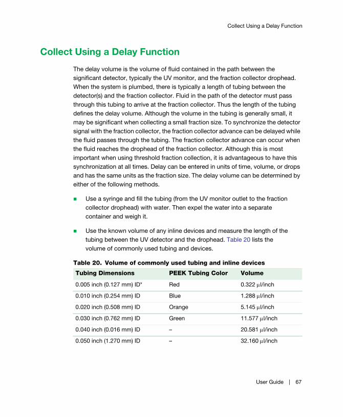
Collect Using a Delay Function
Collect Using a Delay Function
The delay volume is the volume of fluid contained in the path between the
significant detector, typically the UV monitor, and the fraction collector drophead.
When the system is plumbed, there is typically a length of tubing between the
detector(s) and the fraction collector. Fluid in the path of the detector must pass
through this tubing to arrive at the fraction collector. Thus the length of the tubing
defines the delay volume. Although the volume in the tubing is generally small, it
may be significant when collecting a small fraction size. To synchronize the detector
signal with the fraction collector, the fraction collector advance can be delayed while
the fluid passes through the tubing. The fraction collector advance can occur when
the fluid reaches the drophead of the fraction collector. Although this is most
important when using threshold fraction collection, it is advantageous to have this
synchronization at all times. Delay can be entered in units of time, volume, or drops
and has the same units as the fraction size. The delay volume can be determined by
either of the following methods.
Use a syringe and fill the tubing (from the UV monitor outlet to the fraction
collector drophead) with water. Then expel the water into a separate
container and weigh it.
Use the known volume of any inline devices and measure the length of the
tubing between the UV detector and the drophead. Table 20 lists the
volume of commonly used tubing and devices.
Table 20. Volume of commonly used tubing and inline devices
Tubing Dimensions PEEK Tubing Color Volume
0.005 inch (0.127 mm) ID* Red 0.322 l/inch
0.010 inch (0.254 mm) ID Blue 1.288 l/inch
0.020 inch (0.508 mm) ID Orange 5.145 l/inch
0.030 inch (0.762 mm) ID Green 11.577 l/inch
0.040 inch (0.016 mm) ID – 20.581 l/inch
0.050 inch (1.270 mm) ID – 32.160 l/inch
User Guide | 67
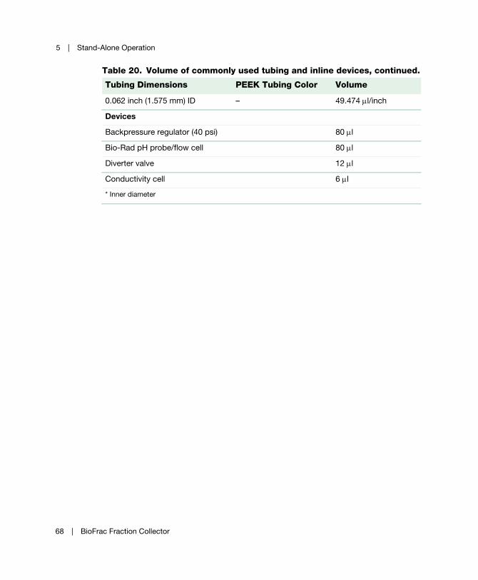
5 | Stand-Alone Operation
0.062 inch (1.575 mm) ID – 49.474 l/inch
Devices
Backpressure regulator (40 psi) 80 l
Bio-Rad pH probe/flow cell 80 l
Diverter valve 12 l
Conductivity cell 6 l
* Inner diameter
Table 20. Volume of commonly used tubing and inline devices, continued.
Tubing Dimensions PEEK Tubing Color Volume
68 | BioFrac Fraction Collector

Collect Using a Delay Function
To run a Collect method using a delay function
1. On the Main screen, set the fraction size units (min, ml, or drops).
2. From the Advanced Collection screen, press Collect (F4).
If collecting by volume, the delay volume can be entered directly. If collecting by
time, the delay time is calculated from the delay volume divided by the flow
rate.
3. To calculate the delay in drops, divide the delay volume by the drop volume
(1 drop = 50 µl for the standard drophead or = 25 µl for the microplate
drophead).
The examples on the following pages demonstrate the use of the delay function.
User Guide | 69

5 | Stand-Alone Operation
Example: Collect All with DelayFigure 27 shows an example in which the delay is 0.2 min and the fraction size is
1 min. The diverter valve remains at divert during the delay time. The chart recorder
makes the first tick mark (following the start/run mark) at 1.0 min, and each
subsequent tick mark at 1 min intervals. The drophead advances at 1.2 min and
continues advancing at 1 min intervals. Each fraction size is still 1 min.
Fig. 27. Example showing Collect All with a delay of 0.2 minutes.
Figure 28 shows an example of a Collect All experiment in Drop mode with a 2-drop
delay and a 10-drop fraction size. In this case the chart recorder makes its first tick
mark (following the start/run mark) at 8 drops:
(fraction size – delay = 10 drops – 2 drops = 8 drops)
70 | BioFrac Fraction Collector

Collect Using a Delay Function
Each subsequent tick mark occurs at 10-drop intervals. The drophead advances at
10-drop intervals following the start of the run. Note that if the delay size equals the
fraction size, the start/run mark and the first event mark are superimposed. This
means that the first observed tick mark (following the start/run mark) corresponds to
the second fraction advance.
Fig. 28. Example showing Collect All with a delay of 2 drops.
Example: Peak Collection by Threshold and DelayFigure 29 shows an example in which Delay is used during the collection of peaks
by threshold. Assume the following for the run:
Flow rate 1 ml/min
Peak fraction size 1 min
Delay time 0.25 min
Threshold value 10% AUFS
Non-peak destination Waste
User Guide | 71

5 | Stand-Alone Operation
At the start of the run an event mark is recorded. Initially the liquid is diverted to
waste because the monitor signal is below threshold. When the UV signal rises
above the specified threshold of 10%, an event mark is recorded and the volume
corresponding to the delay time (or the delay volume) is collected in tube 1. At the
end of this time, there is a tube advance and the peak is collected in 1-minute
fractions. As the falling edge of the peak passes through the threshold, an event
mark is recorded, but there is no tube advance until the volume corresponding to
the delay time is collected. All subsequent peaks follow this same pattern, with a
tube containing the delay volume separating each peak.
Note: When the delay time is set to zero, an empty tube separates the peaks.
Fig. 29. Peak Collection by Threshold using a delay of 0.25 minutes.
When the non-peak (below threshold) liquid is diverted to tubes, the delay volume
(at the rising edge) of the peak is collected as part of the non-peak fraction. To
clearly distinguish between the two types of fractions in this situation, we suggest
programming a much larger non-peak fraction size.
72 | BioFrac Fraction Collector

Collect Using a Delay Function
Example: Collection Using Time Windows and Delay
Case 1, where start time = 5 min and delay time = 0 min Case 2, where start time = 5 min and delay time = 0.25 min
Assume the following:
Note that each time or volume window is separated by a tube containing the delay
volume. If delay time is zero, then tube #1 will be empty and subsequent time or
volume windows collected are separated by empty tubes.
Fig. 30. Collection windows and a delay.
Flow rate 1 ml/min
Peak fraction size 1 min
Time window #1 Start 5, End 8
Time window #2 Start 10, End 12
User Guide | 73

5 | Stand-Alone Operation
74 | BioFrac Fraction Collector

6 LP/Econo Mode Operation
In LP/Econo™ mode all aspects of fraction collection are controlled by an external
controller. In this mode, only Rack, MultiRun, Start Tube, and End Tube parameters
can be set from the fraction collector Main screen. Time and volume windows and
threshold and delay functions are not programmable from the fraction collector in
this mode. However, if the fraction collector is connected to a BioLogic™ LP
chromatography system, Collect All, Threshold, Collection Windows, and Threshold
and Collection Windows (all with delay volume, if desired) can be controlled through
the BioLogic LP system. When the BioFrac™ fraction collector is connected to a
Model EP-1 Econo pump, only Collect All (with delay volume using void (Vo)) is
available. Any controller capable of sending TTL fraction advance and diverter valve
signals can be used in this mode if it has compatible control circuitry logic (see
Appendix B, Rear Panel Connector Information, on page 85).
To run the fraction collector in LP/Econo mode
1. Change mode to LP/Econo and ensure the appropriate cable is connected to
the fraction collector. (See Chapter 3, System Configuration and Plumbing, on
page 13 for cabling information.) Connect system cable 15 to the I/O port on
the fraction collector and to the BioLogic LP system or Model EP-1 Econo
pump.
2. Connect system cable 3 to the Rec port on the BioFrac fraction collector and to
the BioLogic LP System or Model EP-1 Econo pump (see Chapter 3, System
Configuration and Plumbing, on page 13 for cabling information).
3. To select a rack, press Rack (F2) and then choose a rack from the menu.
Choose whether you want the diverter valve to divert to waste during fraction
User Guide | 75

6 | LP/Econo Mode Operation
advances. If you are collecting in microplates or Titertube tubes choose a
collection pattern: Serpentine, Row, or Column.
Note: Whenever a new rack is selected, the start tube and end tube values
are updated to reflect the maximum number of tubes available for the
selected rack.
4. Choose the appropriate MultiRun mode for your experiment (see Table 6 on
page 39 for a description of the MultiRun function).
5. Set the start tube and end tube rack position and tube number as follows:
If you are overlaying fractions, set the start tube and end tube numbers on
the fraction collector to correspond to the required number of fractions
derived from programming the fraction size on the BioLogic LP system, the
Model EP-1 Econo pump, or other controller. For example, assuming the
number of fractions calculated is 30:
If start tube number is A1, then end tube number is A30
If start tube number is B16, then end tube number is B45
If you are doing sequential fraction collection, set Multi Run = Seq. Tube +1
or Seq. Rack and set the start tube and end tube numbers on the fraction
collector to be greater than or equal to the number of fractions required for
the run. When the run is ended by pressing Stop or by reaching the last
tube, the BioFrac fraction collector will automatically increment start tube
and end tube according to the MultiRun function selected (see Table 6 on
page 39).
Alternatively, sequential tube collection can be controlled by the
BioLogic LP chromatography system. In this case, however, no tubes are
skipped between runs. To run in this mode, set MultiRun to Seq. Tube+1 or
Seq. Rack and set end tube to be greater than or equal to the total number
of tubes required for all runs. For example, if you will be doing three runs
requiring 25 tubes each, then 75 tubes are required. Set the MultiRun
parameter on the BioLogic LP system as described in the BioLogic LP
system manual.
76 | BioFrac Fraction Collector
6. Press Engage (F1) to cause the fraction collector to move to the start tube, and
listen for fraction advance and diverter valve signals. The BioFrac will wait for
fraction advance commands from the external controller.
Note: At any point during the run you can use the Run screen’s Stop
function key (see The Run Screen in LP/Econo Mode on page 45) to stop
the fraction collector.
User Guide | 77

6 | LP/Econo Mode Operation
78 | BioFrac Fraction Collector

7 Maintenance and Troubleshooting
Maintenance
The BioFrac™ fraction collector requires little maintenance to ensure reliable
operation. To clean the case, first unplug the fraction collector. Use a damp cloth to
wipe down the outer case. Avoid getting the power switch and rear panel
connectors wet.
Over time the clear glass ring inside the drophead may require cleaning. This ring
protects the drop detector from splashes or dust buildup. To clean the ring, simply
unscrew the inlet fitting and lift out the clear inside ring that protects the detector.
Wipe the ring clean using a damp cloth.
User Guide | 79

7 | Maintenance and Troubleshooting
Fig. 31. Cleaning the drophead window.
When finished using the BioFrac fraction collector, be sure to rinse all salts from the
diverter valve with water. Leaving salt solution in the valve may cause salt crystals to
form, which could plug or damage the valve. Rinsing salt from the valve will increase
the valve’s lifetime.
80 | BioFrac Fraction Collector
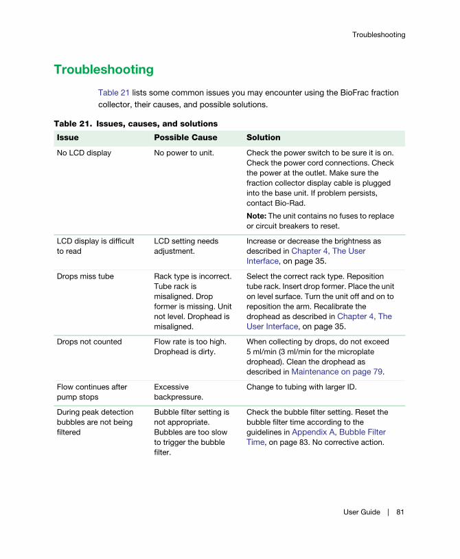
Troubleshooting
Troubleshooting
Table 21 lists some common issues you may encounter using the BioFrac fraction
collector, their causes, and possible solutions.
Table 21. Issues, causes, and solutions
Issue Possible Cause Solution
No LCD display No power to unit. Check the power switch to be sure it is on.
Check the power cord connections. Check
the power at the outlet. Make sure the
fraction collector display cable is plugged
into the base unit. If problem persists,
contact Bio-Rad.
Note: The unit contains no fuses to replace
or circuit breakers to reset.
LCD display is difficult
to read
LCD setting needs
adjustment.
Increase or decrease the brightness as
described in Chapter 4, The User
Interface, on page 35.
Drops miss tube Rack type is incorrect.
Tube rack is
misaligned. Drop
former is missing. Unit
not level. Drophead is
misaligned.
Select the correct rack type. Reposition
tube rack. Insert drop former. Place the unit
on level surface. Turn the unit off and on to
reposition the arm. Recalibrate the
drophead as described in Chapter 4, The
User Interface, on page 35.
Drops not counted Flow rate is too high.
Drophead is dirty.
When collecting by drops, do not exceed
5 ml/min (3 ml/min for the microplate
drophead). Clean the drophead as
described in Maintenance on page 79.
Flow continues after
pump stops
Excessive
backpressure.
Change to tubing with larger ID.
During peak detection
bubbles are not being
filtered
Bubble filter setting is
not appropriate.
Bubbles are too slow
to trigger the bubble
filter.
Check the bubble filter setting. Reset the
bubble filter time according to the
guidelines in Appendix A, Bubble Filter
Time, on page 83. No corrective action.
User Guide | 81

7 | Maintenance and Troubleshooting
Fraction collector
causes a high
backpressure
Tubing is kinked.
Wrong tubing is being
used.
Divert valve or tubing is
plugged.
Replace tubing.
Connect the appropriate size tubing for the
flow rate being used (see Chapter 3,
System Configuration and Plumbing, on
page 13). Rinse the diverter valve with
water to remove salt crystals or other
particulate matter.
Fraction collector will
not go to system mode
when connected to a
BioLogic DuoFlow™
chromatography system
BioFrac system is not
in Main screen.
BioFrac system is not
in Local mode. Bus
cable is not
connected.
Place the fraction collector in Local mode
and make sure the Main screen (start-up
screen) is displayed.
Table 21. Issues, causes, and solutions, continued.
Issue Possible Cause Solution
82 | BioFrac Fraction Collector
A Bubble Filter Time
The bubble filter time function is used in conjunction with the Peak Collection by
Threshold. The bubble filter time function distinguishes true chromatographic peaks
from unwanted signals such as electrical spikes or the passage of an air bubble.
Such false signals are characterized by extremely fast rise and fall times.
The bubble filter time function is entered at the end of the threshold programming
sequence. The default value is off (bubble filter = 0 seconds).
A signal that exceeds the set threshold value with a rise time of >6.0% full scale
(AUFS) in 0.1 seconds is perceived by the fraction collector as possibly signifying a
false peak. In such cases, the fraction collector looks for a bubble filter time set by
the user. If the signal falls to 2% of the pre-rise FS level within the set bubble filter
time, the signal is rejected and the false peak is not collected. Signals that exceed
the threshold value and are of a longer duration than the bubble filter time are
collected as true peaks.
Very sharp, true chromatographic peaks (such as those from an HPLC application)
may rise at a sufficient rate to trigger this function. As a consequence, if an
unsuitable bubble filter time has been set, then the early part of such peaks may not
be collected.
The bubble filter time can be set from 0 to 10 sec. For most chromatographic
applications, a filter time of 0 or 1 sec will suffice. The actual setting depends upon
both flow rate and peak duration and should be optimized for each type of
separation. Generally speaking, a very short bubble filter time should be used with
sharp peaks of short duration.
User Guide | 83
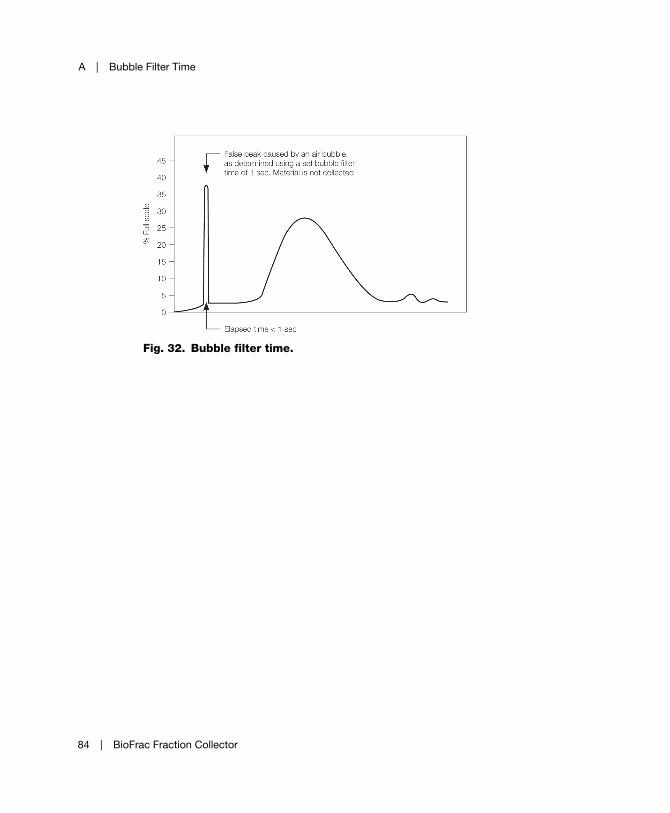
A | Bubble Filter Time
Fig. 32. Bubble filter time.
84 | BioFrac Fraction Collector
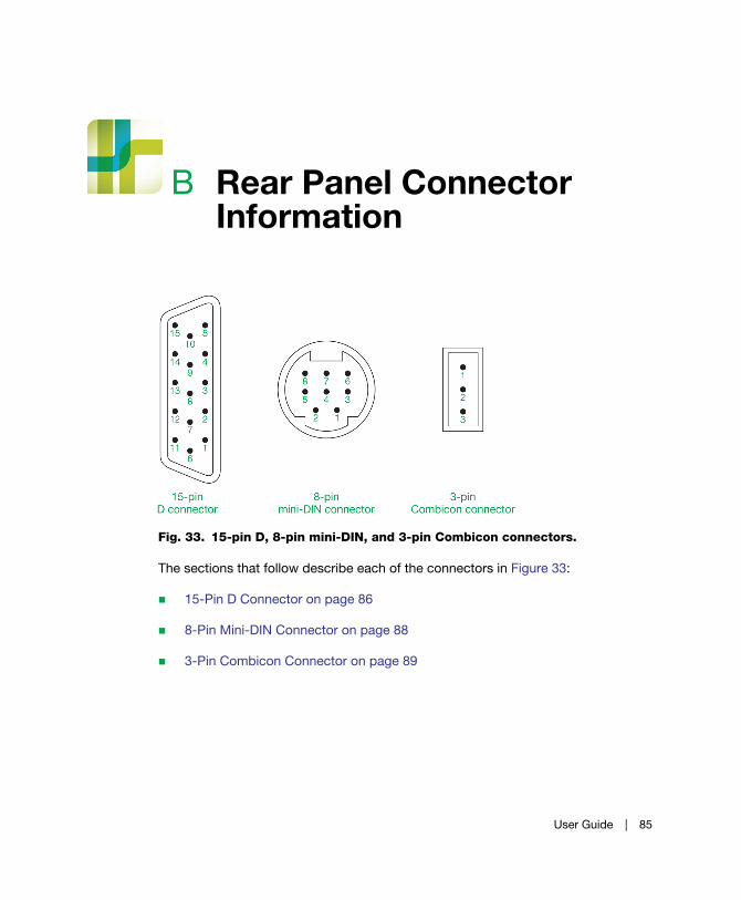
B Rear Panel Connector Information
Fig. 33. 15-pin D, 8-pin mini-DIN, and 3-pin Combicon connectors.
The sections that follow describe each of the connectors in Figure 33:
15-Pin D Connector on page 86
8-Pin Mini-DIN Connector on page 88
3-Pin Combicon Connector on page 89
User Guide | 85
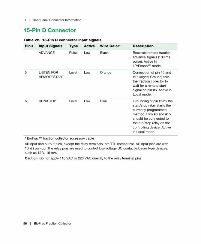
B | Rear Panel Connector Information
15-Pin D Connector
Table 22. 15-Pin D connector input signals
Pin # Input Signals Type Active Wire Color* Description
1 ADVANCE Pulse Low Black Receives remote fraction
advance signals (100 ms
pulse). Active in
LP/Econo™ mode.
5 LISTEN FOR
REMOTE START
Level Low Orange Connection of pin #5 and
#15 (signal Ground) tells
the fraction collector to
wait for a remote start
signal on pin #6. Active in
Local mode.
6 RUN/STOP Level Low Blue Grounding of pin #6 by the
start/stop relay starts the
currently programmed
method. Pins #6 and #15
should be connected to
the run/stop relay on the
controlling device. Active
in Local mode.
* BioFrac™ fraction collector accessory cable
All input and output pins, except the relay terminals, are TTL compatible. All input pins are with
10 k pull-up. The relay pins are used to control low-voltage DC contact-closure type devices,
such as 12 V, 10 mA.
Caution: Do not apply 110 VAC or 220 VAC directly to the relay terminal pins.
86 | BioFrac Fraction Collector

15-Pin D Connector
Table 23. 15-Pin D connector output signals
Pin # Output Signals Type Active Wire Color Description
4 READY Level Low Green Indicates that the fraction
collector diverter valve is
connected and functioning
properly.
9
10
START REMOTE
DEVICE
Relay Closed Green/Black
Orange/Black
Relay used for starting a
remote device such as a
pump. Relay is closed
when Run is pressed and
opened when Stop is
pressed. Active in Local
mode.
11 EVENT MARK Pulse Low Blue/Black Sends a negative pulse
(200 ms) for each fraction
advance. If the delay
function is being used, the
drophead advance will be
separated from the event
mark by the delay time,
volume, or drops.
15 SIGNAL
GROUND
Blue/White Signal ground.
All input and output pins, except the relay terminals, are TTL compatible. All input pins are with
10 k pull-up. The relay pins are used to control low-voltage DC contact-closure type devices,
such as 12 V, 10 mA.
Caution: Do not apply 110 VAC or 220 VAC directly to the relay terminal pins.
User Guide | 87

B | Rear Panel Connector Information
8-Pin Mini-DIN Connector
Table 24. 8-Pin mini DIN connector input signals
Pin #
Input Signals
Type
Active
System Cable 7
Wire Color
Description
2 WASTE/COLLECT Level Low Orange Controls diverter valve.
Connection of pin #2 to
pin #8 (signal ground)
causes the diverter valve
to change to collect.
Controlled by a relay on
a remote device. Active
in LP/Econo mode.
All input and output pins, except the relay terminals, are TTL compatible. All input pins are with 10
k pull-up. The relay pins are used to control low-voltage DC contact-closure type devices, such
as 12 V, 10 mA.
Caution: Do not apply 110 VAC or 220 VAC directly to the relay terminal pins.
Table 25. 8-Pin mini DIN connector output signals
Pin # Output Signals Type Active Wire Color Description
3 EVENT MARK Pulse Low Yellow Sends a negative pulse
(200 ms) for each
fraction advance. If the
delay function is being
used, the drophead
advance will be
separated from the
event mark by the delay
time, volume, or drops.
Active in Local mode.
4 PAPER FEED/
STOP
Level High Red Chart recorder control,
paper feed/stop. Active
in Local mode.
88 | BioFrac Fraction Collector

3-Pin Combicon Connector
3-Pin Combicon Connector
5 PEN UP/DOWN Level Low Brown Chart recorder control,
pen up/down. Active in
Local mode.
6, 7 ADS TERMINAL Level Low Purple blue Event marks for Method
Start and Fraction
Advance by way of a
relay. Pins #6 and #7 are
closed for 200 ms with
each fraction advance.
Active in Local mode.
8 SIGNAL GROUND Green Signal ground.
All input and output pins, except the relay terminals, are TTL compatible. All input pins are with
10 k pull-up. The relay pins are used to control low-voltage DC contact-closure type devices,
such as 12 V, 10 mA.
Caution: Do not apply 110 VAC or 220 VAC directly to the relay terminal pins.
Table 25. 8-Pin mini DIN connector output signals, continued.
Pin # Output Signals Type Active Wire Color Description
Table 26. 3-Pin Combicon connector
Pin # Input Signals Type Active Description
1 ANALOG
GROUND
Common UV monitor input: analog ground
2 ANALOG IN(–) Input UV monitor input 100 mV and 1 V (–)
3 ANALOG IN(+) Input UV monitor input 100 mV and 1 V (+)
User Guide | 89

B | Rear Panel Connector Information
90 | BioFrac Fraction Collector
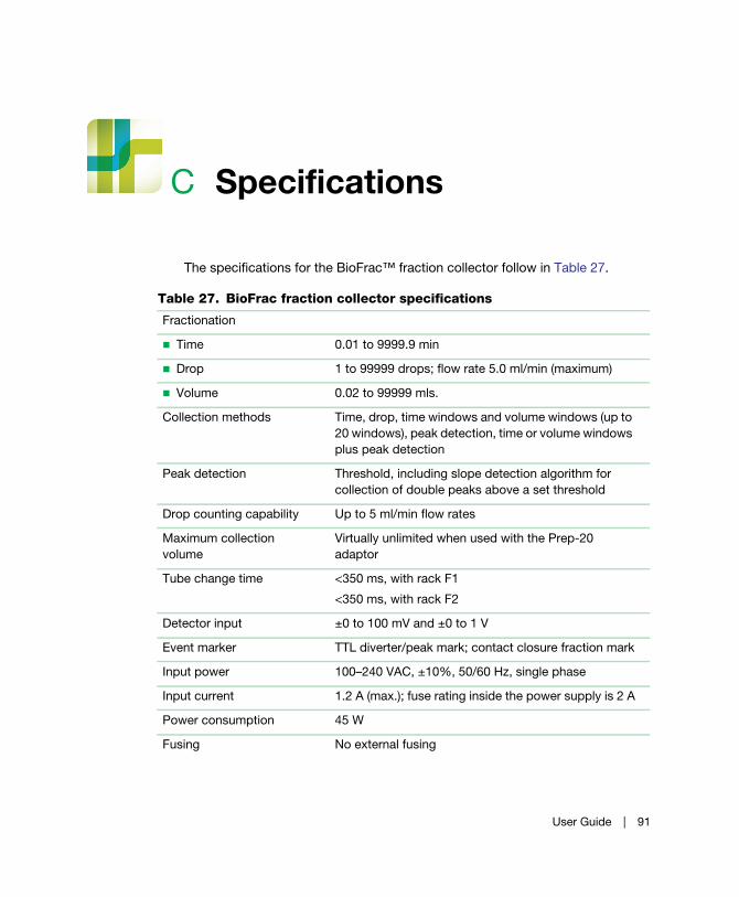
C Specifications
The specifications for the BioFrac™ fraction collector follow in Table 27.
Table 27. BioFrac fraction collector specifications
Fractionation
Time 0.01 to 9999.9 min
Drop 1 to 99999 drops; flow rate 5.0 ml/min (maximum)
Volume 0.02 to 99999 mls.
Collection methods Time, drop, time windows and volume windows (up to
20 windows), peak detection, time or volume windows
plus peak detection
Peak detection Threshold, including slope detection algorithm for
collection of double peaks above a set threshold
Drop counting capability Up to 5 ml/min flow rates
Maximum collection
volume
Virtually unlimited when used with the Prep-20
adaptor
Tube change time <350 ms, with rack F1
<350 ms, with rack F2
Detector input ±0 to 100 mV and ±0 to 1 V
Event marker TTL diverter/peak mark; contact closure fraction mark
Input power 100–240 VAC, ±10%, 50/60 Hz, single phase
Input current 1.2 A (max.); fuse rating inside the power supply is 2 A
Power consumption 45 W
Fusing No external fusing
User Guide | 91
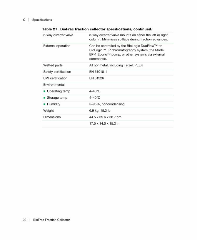
C | Specifications
3-way diverter valve 3-way diverter valve mounts on either the left or right
column. Minimizes spillage during fraction advances.
External operation Can be controlled by the BioLogic DuoFlow™ or
BioLogic™ LP chromatography system, the Model
EP-1 Econo™ pump, or other systems via external
commands.
Wetted parts All nonmetal, including Tefzel, PEEK
Safety certification EN 61010-1
EMI certification EN 61326
Environmental
Operating temp 4–40°C
Storage temp 4–40°C
Humidity 5–95%, noncondensing
Weight 6.9 kg; 15.3 lb
Dimensions 44.5 x 35.6 x 38.7 cm
17.5 x 14.0 x 15.2 in
Table 27. BioFrac fraction collector specifications, continued.
92 | BioFrac Fraction Collector
D Warranty and Ordering Information
The BioFrac™ fraction collector is warranted for one year against defects in
materials and workmanship. If any defects should occur during this warranty period,
Bio-Rad Laboratories will replace the defective parts without charge. However, the
following defects are specifically excluded:
Defects caused by improper operation
Repair or modification done by anyone other than Bio-Rad Laboratories or
their authorized agent
Defects caused by use with fittings or other spare parts not specified by
Bio-Rad Laboratories
Damage caused by deliberate or accidental misuse
Damage caused by disaster
Damage due to use of improper solvent or sample
Tubing and fittings
User Guide | 93

D | Warranty and Ordering Information
Warranty Information
Model ___________________________________________________________________
Serial Number ____________________________________________________________
Date of Delivery ___________________________________________________________
Warranty Period ___________________________________________________________
Ordering Information
Catalog
Number
Product Description
741-0002 BioFrac Fraction Collector, includes a 110 V power cord, rack F1(2), Econo™
system cable 15, and fittings kit
741-0010 Rack Set F1, accepts 12–13 mm diameter tubes (90 tubes max)
741-0011 Rack Set F2, accepts 15–16 mm diameter tubes (60 tubes max)
741-0012 Rack Set F3, accepts 18–20 mm diameter tubes (40 tubes max)
741-0013 Rack Set H1, accepts 42 capless 1.5 ml Eppendorf/microtubes (168 tubes max)
741-0014 Rack Set H2, accepts 63 capless 0.5 ml Eppendorf/microtubes (252 tubes max)
741-0015 Rack Set H3, accepts 30 reduced-volume scintillation vials, 16 mm (120 vials max)
741-0016 Rack Set H4, accepts 6 scintillation vials, 30 mm (24 vials max)
741-0017 BioFrac Ice Bath/Microplate Rack, holds 120 tubes, 12–13 mm, on ice or up to
4 microplates/Titertube racks (SBS standard format)
741-0018 BioFrac Prep-20 Rack, for preparative collection in up to 20 collection vessels,
includes drain tubing and 20 feet of Tygon tubing
741-0008 BioFrac Diverter Valve
741-0088 BioFrac Microplate Drophead Kit, includes drophead that delivers 25 µl drops
compared to standard drophead delivery of 50 µl
731-8286 System Cable 15, 15-pin D to mini-DIN, for connecting the fraction collector to the
BioLogic™ LP system controller or the Model EP-1 Econo pump
94 | BioFrac Fraction Collector
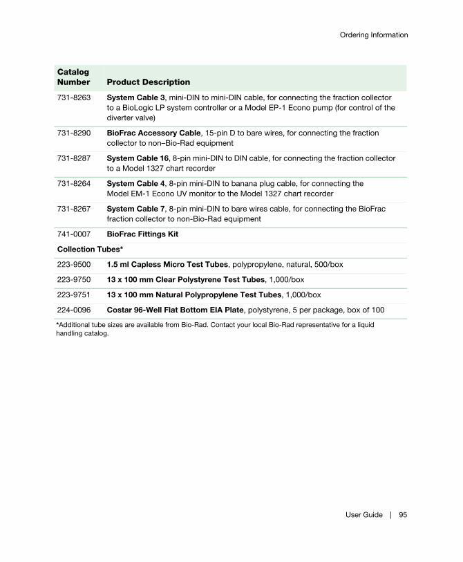
Ordering Information
731-8263 System Cable 3, mini-DIN to mini-DIN cable, for connecting the fraction collector
to a BioLogic LP system controller or a Model EP-1 Econo pump (for control of the
diverter valve)
731-8290 BioFrac Accessory Cable, 15-pin D to bare wires, for connecting the fraction
collector to non–Bio-Rad equipment
731-8287 System Cable 16, 8-pin mini-DIN to DIN cable, for connecting the fraction collector
to a Model 1327 chart recorder
731-8264 System Cable 4, 8-pin mini-DIN to banana plug cable, for connecting the
Model EM-1 Econo UV monitor to the Model 1327 chart recorder
731-8267 System Cable 7, 8-pin mini-DIN to bare wires cable, for connecting the BioFrac
fraction collector to non-Bio-Rad equipment
741-0007 BioFrac Fittings Kit
Collection Tubes*
223-9500 1.5 ml Capless Micro Test Tubes, polypropylene, natural, 500/box
223-9750 13 x 100 mm Clear Polystyrene Test Tubes, 1,000/box
223-9751 13 x 100 mm Natural Polypropylene Test Tubes, 1,000/box
224-0096 Costar 96-Well Flat Bottom EIA Plate, polystyrene, 5 per package, box of 100
*Additional tube sizes are available from Bio-Rad. Contact your local Bio-Rad representative for a liquid
handling catalog.
Catalog
Number
Product Description
User Guide | 95

D | Warranty and Ordering Information
96 | BioFrac Fraction Collector

Life ScienceGroup
11-1653 0612 Sig 12114006211 Rev C US/EG
Bio-Rad Laboratories, Inc.
Web site www.bio-rad.com USA 800 424 6723 Australia 61 2 9914 2800 Austria 01 877 89 01 Belgium 09 385 55 11 Brazil 55 11 5044 5699 Canada 905 364 3435 China 86 21 6169 8500 Czech Republic 420 241 430 532 Denmark 44 52 10 00 Finland 09 804 22 00 France 01 47 95 69 65 Germany 089 31 884 0 Greece 30 210 9532 220 Hong Kong 852 2789 3300 Hungary 36 1 459 6100 India 91 124 4029300 Israel 03 963 6050 Italy 39 02 216091 Japan 03 6361 7000 Korea 82 2 3473 4460 Mexico 52 555 488 7670 The Netherlands 0318 540666 New Zealand 64 9 415 2280 Norway 23 38 41 30 Poland 48 22 331 99 99 Portugal 351 21 472 7700 Russia 7 495 721 14 04 Singapore 65 6415 3188 South Africa 27 861 246 723 Spain 34 91 590 5200 Sweden 08 555 12700 Switzerland 061 717 95 55 Taiwan 886 2 2578 7189 Thailand 800 88 22 88 United Kingdom 020 8328 2000