prostar 704 fraction collector - Природные и...
TRANSCRIPT

Varian, Inc. 2700 Mitchell Drive Walnut Creek, CA 94598-1675/usa
©Varian, Inc. 1999 Printed in U.S.A. 03-914796-00:Rev. 2
ProStar 704 Fraction Collector
Operation Manual


ProStar 704 Fraction Collector i
Table of Contents
Introduction.............................................................................................. 1 Features...............................................................................................................................2 Racks & Vessels..................................................................................................................3 Peak Detection ....................................................................................................................3 Front Panel Controls............................................................................................................4 Rear Panel Connectors .......................................................................................................5
Installation................................................................................................ 7 Preliminary Checkout ..........................................................................................................7 Drop Former Installation ....................................................................................................11 Rack Installation ................................................................................................................12 Micro Collection Tray.........................................................................................................13 Funnel Tray........................................................................................................................14 Container Collection ..........................................................................................................14 Height Adjustment .............................................................................................................16 External System Connections ...........................................................................................17 Drip Tray Drain ..................................................................................................................18
Instrument Description ......................................................................... 19 Mechanical Description .....................................................................................................19
Operation................................................................................................ 23 Introduction ........................................................................................................................23
Keyboard and Display.................................................................................................24 Programming Overview .....................................................................................................25
Programming Tips.......................................................................................................25 Creating a New Program ............................................................................................26
Running a Program ...........................................................................................................30 Viewing Program Steps ..............................................................................................31 Pausing/Ending a Program .........................................................................................31 Using the Advance Key...............................................................................................31 Clearing a Program.....................................................................................................32
Sample Programs..............................................................................................................32 Entering a Fraction by Time Program.........................................................................33 Entering a Fraction by Drops Program .......................................................................34

ii 03-914796-00:2
Entering a Peak Detect Program ................................................................................36 Entering a Time Window Program..............................................................................40
Peak Separator and Time Windows..................................................................................43 Level Sensing..............................................................................................................44 Slope Detection...........................................................................................................45 Slope Detection and Level Sensing............................................................................46 Time Windows.............................................................................................................46
Flow Delay, Outputs, Inject Action, Valve and Pump Control ...........................................49 Flow Delay ..................................................................................................................49 Outputs........................................................................................................................49 Inject Action.................................................................................................................50 Valve and Pump Control .............................................................................................50
Software Reference...........................................................................................................51 Key Definitions ............................................................................................................51 Main Menu Softkeys....................................................................................................54
Maintenance and Repair ....................................................................... 61 Introduction ........................................................................................................................61
LC Technical Service Department ..............................................................................61 Disassembly and Repair....................................................................................................62
Cleaning the Drip Tray ................................................................................................62 Cleaning the Drop Counter Sleeve .............................................................................62 Removing the Upper Case Back Panel ......................................................................64 Separating the Case Halves and Removing the Lower Case Back Panel .................65 Interconnect Cable Connections.................................................................................68 Removing the Arm ......................................................................................................69 Installing the Arm ........................................................................................................72 Replacing the Keyboard..............................................................................................73 Replacing the Liquid Crystal Display ..........................................................................75 Replacing the Left-to-Right Motor ...............................................................................76 Replacing the Arm Circuit Board.................................................................................78 Replacing the Drop Counter Circuit Board .................................................................80 Replacing the Front-Back Axis Drive Components ....................................................82 Replacing the Left-to-Right Motor Timing Belt............................................................84 Replacing the Rolling Cable........................................................................................85
Appendices ............................................................................................ 89 Specifications.....................................................................................................................89 Glossary.............................................................................................................................90 Standard Accessories........................................................................................................91 Optional Accessories.........................................................................................................91

ProStar 704 Fraction Collector iii
Available Valves..........................................................................................................92 Installing a Valve................................................................................................................94
Inlet Tubing Routing ....................................................................................................96 Small Diameter Tubing................................................................................................96 Routing to an Accessory Valve ...................................................................................98 Large Diameter Tubing ...............................................................................................99
Connection to an Absorbance Detector ......................................................................... 100 Connection to Other Pumps ........................................................................................... 101
ProStar 704 Input/Output Connectors ..................................................................... 101
INDEX.................................................................................................... 105
Tables Table 1 ProStar 704 Front Panel Controls ..........................................................................5 Table 2 ProStar 704 Rear...................................................................................................6 Table 3 ProStar 704 Rear Panel Connectors................................................................. 102 Table 4 ProStar 704 Pump Connector Pin-outs............................................................. 102 Table 5 ProStar 704 Detector Connector Pin-outs......................................................... 103 Table 6 ProStar 704 Serial Connector Pin-outs ............................................................. 104

iv 03-914796-00:2
Figures
Figure 1 ProStar 704 ...........................................................................................................1 Figure 2 Front Panel Controls .............................................................................................4 Figure 3 Rear Panel ............................................................................................................5 Figure 4 Main Menu.............................................................................................................8 Figure 5 Remove Drop Former ........................................................................................11 Figure 6 Install Inlet Tubing ...............................................................................................12 Figure 7 Install Test Tube Rack ........................................................................................13 Figure 8 Micro Collection Tray...........................................................................................13 Figure 9 Registration Marks on Drip Pan ..........................................................................15 Figure 10 150 mL Bottles Positioned on Drip Pan ............................................................15 Figure 11 Height Adjustment ............................................................................................17 Figure 12 Keyboard and Display ......................................................................................24 Figure 13 Level Sensing Collection...................................................................................44 Figure 14 Peak Detector Collection...................................................................................45 Figure 15 Time Windows Collection..................................................................................47 Figure 16 Time Windows/Level Sensing ...........................................................................48 Figure 17 Remove Drop Former .......................................................................................63 Figure 18 Upper Case Back Screws, Interlock Bolt ..........................................................64 Figure 19 Remove case bottom screws............................................................................66 Figure 20 Cable Locations on Circuit Boards, Case Disassembly....................................67 Figure 21 Exploded View...................................................................................................69 Figure 22 Removing timing belt (Exploded view)..............................................................71 Figure 23 Replacing the Left-to-Right Motor .....................................................................77 Figure 24 Removing Arm Circuit Board Hardware............................................................79 Figure 25 Replacing Drop Counter Circuit Board..............................................................81 Figure 26 Front-to-Back Drive Assembly ..........................................................................83 Figure 27 Remove Timing Belt from Arm ..........................................................................84 Figure 28 Rolling Cable Mounting Hardware ....................................................................86 Figure 29 Rolling Cable and Clamp (top view)..................................................................87 Figure 30 ProStar 704 with Valve Installed .......................................................................93 Figure 31 Install Valve on Arm ..........................................................................................94 Figure 32 Attach Valve Cable............................................................................................95 Figure 33 Attach Tubing to Valve ......................................................................................96 Figure 34 Small Diameter Tubing Routing ........................................................................97 Figure 35 Routing Tubing with Accessory Valve...............................................................98 Figure 36 Routing Large Diameter Tubing........................................................................99

ProStar 704 Fraction Collector 1
Introduction The Varian ProStar 704 Fraction Collector provides easy-to-use, interactive programming and intuitive operation. Microprocessor control and advanced software allow you to program the ProStar 704 quickly and easily for almost any collection routine.
ProStar 704 is shown in Figure 1.
Figure 1 ProStar 704

2 03-914796-00:2
Features • Basic collection of uniform fractions with fraction sizes set by
time, drop count, or external signal count.
• A variety of peak detection schemes including:
• slope (rate of change in detector output)
• threshold level sensing
• time windows
• time windows and slope
• time windows and level sensing
• slope and level sensing
• time windows, slope and level sensing
• A delay time may be programmed to synchronize the ProStar 704 with the detector.
• Diversion of initial void volume or waste, using either the built-in waste drain or optional 3-way drain valve.
• An optional anti-drip or drain valve is available.
User-friendly software makes programming easy. You can set all collection parameters to customize your collection routines. Fraction collection can be controlled by time, counted drops, pump revolutions, or external signals. This programming flexibility enables you to tailor a run to any application quickly.
Up to nine collection programs can be saved and recalled simply by pressing one of the numeric keys on the ProStar 704 keyboard. Different operators can create and save their own programs, facilitating multi-user operation. Any saved program can be recalled and edited to meet new requirements. All changes are automatically saved as you edit. All nine programs remain in memory as long as the instrument is connected to main power or the internal NiCad battery remains charged.

Introduction
ProStar 704 Fraction Collector 3
ProStar 704 is programmed through a spill-resistant membrane keyboard consisting of function-specific softkeys. The LCD display allows the instrument to prompt you for program options and operating conditions. Easy-to-follow messages guide you through the programming steps. During a run, the display provides continually updated information on operating conditions.
Racks & Vessels ProStar 704 is supplied with a chemically-resistant stainless steel and polypropylene tube rack designed for 13 mm diameter test tubes. Other racks are available for 12, 16, 18, and 25 mm diameter test tubes, MiniVials®, 28 mm scintillation vials, 1.5 mL micro centrifuge tubes, standard 50 mL centrifuge tubes, and prep funnel racks. The polypropylene drip pan has tabs which accurately position up to nine 150 mL bottles or a single, larger container. The ProStar 704 case is designed to allow you to adjust the height of the instrument to accommodate 100 mm, 125 mm, and 150 mm collection vessels. Test tube rack configurations are preprogrammed into the ProStar 704. Selecting a standard tube size also sets the maximum number of tubes. Smaller numbers of tubes can be programmed if needed to accommodate your applications.
During collection, the tubes remain stationary while the moving collection arm positions the drop former over the appropriate tube. When a run is complete, the drop former returns to the waste drain where unwanted effluent is diverted to waste.
Peak Detection The built-in peak detector allows collection based on signals from a separate UV, fluorescence, or other detector. Up to 10 time windows defining important areas may be programmed for collection. Unwanted peaks may be diverted to waste through the waste drain or optional drain valve.

4 03-914796-00:2
ProStar 704 automatically controls an anti-drip (on-off) valve to prevent loss of sample when changing tubes, or actuates a drain valve (3-way) to prevent pressure build up between tubes. It can also interrupt pump operation when indexing tubes, at the end of a run, or manually.
Front Panel Controls The front panel controls on the ProStar 704 consist of a 17-key membrane keypad and a 48-character LCD (liquid crystal display). The keys have a tactile “click” as well as an audible tone to indicate that you have pressed a key. The alphanumeric display gives the ProStar 704 programming flexibility and allows it to communicate a wide range of information. The contrast can be adjusted for comfortable viewing.
Table 1 describes the front panel controls called out in Figure 2.
A B C D E
ADVANCE
STANDBYOPERATE
1 2 3 4 5
6 7 8 9 0
FRACTION COLLECTORProStar 704
1
2
3
4
5
Figure 2 Front Panel Controls

Introduction
ProStar 704 Fraction Collector 5
Table 1 ProStar 704 Front Panel Controls
Item Control Description 1 Advance Key Provides manual control of drop former position,
valve and pump operation. 2 Standby/Operate Key Switches the instrument between operate and
standby modes, without disconnecting power. 3 Softkeys Labeled A, B, C, D, and E—used to select menu
items displayed on the liquid crystal display. 4 Numeric Keypad Used to enter numeric data. 5 Liquid Crystal Display 2 lines x 24 characters total display area.
Rear Panel Connectors The rear panel has connectors allowing external detector input, pump control, and serial connection to a computer and/or other instruments.
The rear panel connectors are described in Table 2.
Figure 3 Rear Panel

6 03-914796-00:2
Table 2 ProStar 704 Rear
Item Item/Connector Description 1 Serial tag Indicates the serial number of the instrument. 2 Power connector From wall power adapter. 3 Detector (8-pin DIN) Interface connection to the detector for
automatic peak separation, event marking, inject action, and external advance.
4 Pump (6-pin DIN) Provides stop signal to pump at the end of the run and optionally at the start of the 0.8 second delay between tubes. Also provides a count input for the valve controller.
5 RS-232-C (25-pin D-Sub) Serial interface.

ProStar 704 Fraction Collector 7
Installation This section describes the setup procedures for ProStar 704 and its optional accessories. Tools required to install accessories are listed at the beginning of each procedure.
Before attempting to assemble or operate the ProStar 704, ensure that all parts listed on the packing slip are in the shipping carton(s). All items ordered, including test tube racks and optional valves, are listed on the packing slip.
NOTE: Any optional accessories ordered with ProStar 704 will be shipped in a separate carton.
Inspect the instrument ProStar 704 for damage which may have occurred during shipping. Damage in transit is the responsibility of the carrier, not the manufacturer, so you should notify the shipping carrier immediately if you find any damage. Keep the shipping container and all packing, it will be needed for inspection by the carrier if you file a damage claim.
Preliminary Checkout Before using ProStar 704, you need to perform a preliminary checkout sequence. This includes testing electrical, mechanical, and programming functions. You will also need to enter a simple program.
NOTE: Do not install any accessories until preliminary checkout has been completed.
Set ProStar 704 upright on a level surface.
Connect ProStar 704 to power mains. The display should be off.
8 03-914796-00:2
Press the Standby/Operate key on the keyboard. The drop former should move to the right rear of drip pan, over the waste drain. The display momentarily displays:
Version XX.XX.XX Copyrighted Rev X.
ProStar 704 prompts you through its programming steps with a series of simple menus. After you make your programming selection and press the Enter softkey, the next menu prompts you for another program step.
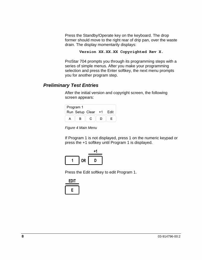
Preliminary Test Entries After the initial version and copyright screen, the following screen appears:
Figure 4 Main Menu
If Program 1 is not displayed, press 1 on the numeric keypad or press the +1 softkey until Program 1 is displayed.
Press the Edit softkey to edit Program 1.

Installation
ProStar 704 Fraction Collector 9
The next screen prompts you to select a collection mode. Press either Select softkey (C or D) until Fraction by time is displayed; press Enter.
The next screen prompts you to select the collection time. Enter 10 seconds by pressing 1, 0 on the numeric keypad; press Enter.
Press Enter 7 times to bypass programming steps not needed for this test program.
The next screen prompts you to select the rack in use. Press either Select softkey until the rack you have installed appears on the screen; press Enter.
The next screen prompts you to enter the last tube in the run. Press 2 on the numeric keypad and press Enter.

10 03-914796-00:2
Press the End softkey to exit the program edit mode.
Operational Test: Press the Run softkey. The drop former should advance to front left of the drip pan. The screen should display Tube = 1 and the running time. After 10 seconds, the drop former should move to tube 2. After 10 seconds over tube 2, the drop former should return to the park position over the waste drain.
Press the End softkey when the program is done. This completes the preliminary checkout sequence.
Disconnect the instrument from AC power. If the preliminary checkout ran satisfactorily, complete the preparatory steps in this section and then refer to the Operation section beginning on page 23 for operating instructions and the Standard Accessories section beginning on page 91 for connection of accessories.
If ProStar 704 failed any of the tests outlined here, contact LC Technical Service Department at 1-800-FOR-HPLC.

Installation
ProStar 704 Fraction Collector 11
Drop Former Installation Before connecting inlet tubing, remove the drop former and complete the tubing connection while holding the drop former in your hand.
To Remove Drop Former To access the drop former, connect the instrument to power mains using the supplied wall power pack. Press the Standby/Operate key and press the Advance key. Press 1, Enter, and then the Tube softkey. The drop former moves to an accessible location.
Hold the drop counter assembly with one hand and grasp the drop former with the other, as shown in Figure 5.
Pull straight up on the drop former to remove it from the drop counter assembly. Rotating the drop former while pulling upward may ease removal.
1 Support drop counter assembly here
Figure 5 Remove Drop Former

12 03-914796-00:2
To Install Inlet Tubing and Drop Former Unscrew the lead connector nut from the lead connector.
Guide the tubing through the nut and an appropriately sized ferrule into the lead connector, as shown in Figure 6.
Push the ferrule into the lead connector and tighten the lead connector nut on the drop former.
Support the underside of the drop counter assembly and press the drop former firmly into place.
1 Inlet Tubing 2 Lead connector nut 3 Ferrule 4 Lead connector on drop former
Figure 6 Install Inlet Tubing
Rack Installation The drip pan accommodates one rack. All racks are keyed to prevent improper installation; however, you should ensure that the rack rests flat on the drip pan. The rack is properly oriented if the test tube numbers appear upright when viewing the instrument from the front. Make sure the drop former is in the park position. Set the rack on the drip pan at a slight angle as shown in Figure 7, align the index pins, and press the rack into place on the pins.

Installation
ProStar 704 Fraction Collector 13
Figure 7 Install Test Tube Rack
Micro Collection Tray These chemically resistant polypropylene trays are ideal for collecting small (0.5 mL or less) fractions. Each tray has 72 conical sample wells arranged in a matrix conforming to the tube spacing of both 12 mm and 13 mm racks. Up to two trays per rack can be used. They may be placed directly on the rack or on top of test tubes. These trays have a special drop dispenser feature which breaks the drop as it falls in the tray, preventing your sample material from splashing out of the shallow collection well. Micro collection trays may be ordered in packages of ten (part number R000088416).
Figure 8 Micro Collection Tray

14 03-914796-00:2
Funnel Tray Each 12 and 13 mm test tube rack is shipped with two chemically resistant polypropylene funnel trays. The molded tray consists of a matrix of 72 funnels which, when inserted into the test tubes in the racks, ensure that no effluent drops between the tubes. These trays are ideal for collecting radioactive materials because they protect against contamination of the test tube racks. Two trays can be used per rack.
Because the diameter of 12 mm tubes is so small, a minor variation in the evenness of the surface on which ProStar 704 is sitting may increase the risk of drops not hitting the tubes. Therefore, the funnel trays are recommended for use when collecting in 12 mm tubes.
Additional funnel trays may be ordered in packages of ten (part number R000088424).
Container Collection No racks are required for container collection. ProStar 704 accommodates up to nine 150 mL bottles. The proper position of these containers is indicated by raised registration marks on the drip pan. Alternatively, a single, large container may be placed at the center of the drip pan.

Installation
ProStar 704 Fraction Collector 15
1 Registration marks Figure 9 Registration Marks on Drip Pan
1 150 mL bottle
Figure 10 150 mL Bottles Positioned on Drip Pan

16 03-914796-00:2
Height Adjustment To accommodate collection vessels of different sizes, ProStar 704 has a three-position height adjustment. The height can be set for 100 mm, 125 mm, and 150 mm collection vessels.
The telescoping mechanism is incorporated into both the upper and lower case halves. The upper case half has protrusions which engage a set of mating locating features molded into the lower case half. The two parts are held together by a pair of locking cams which are attached to the upper case back panel and press against the lower case half. Three sets of reliefs are molded into the lower case half, one for each height setting. A shoulder screw which slides in a slot in the upper case back panel and is attached to the lower case back panel prevents the instrument from accidentally coming apart.
Adjust the height by loosening the locking cams, sliding the upper enclosure forward, lifting the upper enclosure up to the desired position and tightening the locking cams. Locate the three height settings by pressing the upper case half of the instrument rearward while moving it slowly up and down. You will feel a slight detent as the upper case half locating features align with those in the lower case half.
NOTE: Remove the test tube rack when adjusting to or from the lowest (100 mm) height position.

Installation
ProStar 704 Fraction Collector 17
1 Rotate locking cams up to unlock; rotate locking cams down to lock new height.
Figure 11 Height Adjustment
External System Connections
An extra-long length of 0.020" ID Teflon (PTFE) tubing is recommended. This allows connection between the flow cell of the monitor and other devices. To minimize transit delay times, the smallest bore tubing compatible with your system’s pressure and flow should be used. The tubing should be cut as short as is convenient to reach your column or flow cell location. For information about interfacing a fraction collector with your absorbance detector interface, consult your absorbance detector manual.
See the Operation Section for complete information on using peak detection based on absorbance detector signal.
Lift to raise
18 03-914796-00:2
Drip Tray Drain The drip tray provided with ProStar 704 has a drain located at its right rear corner which protrudes through the lower enclosure. The drip tray drain is designed to be fitted with 0.375-inch ID tubing. The waste tube may be routed through a channel and out the back of the ProStar 704, or it may be routed under the edge of the instrument.

ProStar 704 Fraction Collector 19
Instrument Description The ProStar 704 is a microprocessor-based XY fraction collector designed to provide both simple and sophisticated collection along with ease of programming and operation. Microprocessor control and advanced software allow you to program the ProStar 704 quickly for a variety of collection schemes. The ProStar 704 includes a sophisticated peak separator which greatly increases its versatility and scope.
Mechanical Description The ProStar 704 molded telescoping case enclosing the electronics and the mechanism which moves the drop former left to right. The front-to-back mechanism is contained entirely in the arm assembly. The telescoping case consists of an upper section and a lower section held together by a cam-actuated locking mechanism. The upper and lower enclosures are tethered to prevent them separating. The upper enclosure, made of polyphtalamide (PPA), contains mounts for the left-to-right mechanism, the Liquid Crystal Display (LCD), the keyboard panel, the interior shield, the upper case rear panel, and the left-to-right home flag.
The left-to-right mechanism consists of an arm assembly sliding on a hardened stainless steel (SST) rod. The arm assembly has a molded bushing that rides on the SST guide rod. A small roller on the arm rides on an aluminum rail. The arm is attached to a timing belt driven by a stepper motor. The idler pulley is adjustable to allow the timing belt tension to be set. The stepper motor is mounted with rubber isolators to control noise.
The arm assembly contains the front-to-back mechanism. The front-to-back mechanism, an integral part of the arm assembly, is a push-pull design. The drop counter housing is attached to a perforated ribbon cable, held in a molded track in the two PPA halves of the arm. The cable is driven by an acetal (POM) ring gear with special teeth around its circumference which engage perforations in the ribbon cable. The ring gear rotates in bearing
20 03-914796-00:2
surfaces molded into the arm. The ring gear is also the output of an epicyclic gear reduction consisting of the ring gear, a planet gear, a sliding block and a cam. The planet gear is molded PPA and has two integral pins molded into it. These pins engage two slots in the sliding block to prevent the planet gear rotating. The acetal sliding block moves in a slot molded into the arm. The planet gear has a ball bearing pressed into its center. The SST cam, pressed on the front-to-back stepper motor shaft, is located inside the inner race of the ball bearing in the planet gear. As the cam is rotated by the stepper motor, the planet gear is forced to move in a circular pattern without rotating. The ring gear, engaged with the planet gear, rotates in its bearing but much slower than the cam.
The LCD assembly is attached to the upper enclosure by tour screws. The screws are threaded into two grooves located on either side of the display window. The display cable is routed over the top of the interior shield, down between the upper case back panel and the back of the interior shield and is plugged into the main circuit board assembly.
The polyester keyboard is fixed to the upper enclosure from the outside with its cable entering the case through a clearance slot. The cable is routed over the top of the interior shield, between the upper case rear panel and the back of the interior shield, and is plugged into the main circuit board assembly (OBA).
The lower enclosure contains most of the electronics and has -in features to retain the lower case rear panel and to locate the drip tray, test tube rack, and the rubber feet. The lower enclosure is also molded PPA. Four pins retain the drip tray and position the test tube rack. A groove located in the back of the case positions and retains the lower enclosure rear panel. Two screws engage the lower case rear panel from the underside of the instrument to secure it in place. Circuit board guides are molded into the bottom front of the enclosure, forming mounts for the bottom of the main CBA. The top of the main CBA is held by two circuit board standoffs positioned in two grooves in the top of the enclosure area. The power CBA is attached to the inside of the lower case rear panel.

Instrument Description
ProStar 704 Fraction Collector 21
The telescoping mechanism is incorporated into both upper and lower enclosures. Protrusions in the upper enclosure engage a set of mating detents molded into the lower enclosure. The two parts are held together by a pair of locking cams, attached to the upper case back panel. The locking cams press against the lower enclosure and pull the upper enclosure protrusions into the matching lower enclosure detents. Several sets of detents are molded into the lower enclosure so that the height can be adjusted to handle 100, 125, and 150 mm height test tubes. A shoulder screw which slides in a slot in the upper case back panel and is attached to the lower case back panel, prevents the unit from accidentally coming apart. The height is adjusted by loosening the locking cams, sliding the upper enclosure forward, lifting the upper enclosure up to the desired position and tightening the locking cams.
The test tube racks fit in a removable polypropylene (PP) drip tray. The ProStar 704 accommodates standard racks for 12, 13, 16, 18, 25, and 28 mm tubes, MicroVials, and microcentrifuge vials. Without a rack in position, the drip tray will hold 9 bottles or a single large beaker. A 36-position prep funnel rack is also available. The drip tray drain is located at the right rear comer of the tray and protrudes through the lower enclosure. It is designed for 0.375" ID tubing. The waste tube may be routed through a channel and out the back of the ProStar 704, or it may be routed under the edge of the instrument.
A polypropylene waste trough is provided for waste diversion. The waste trough is located behind the test tube rack and is attached to the upper enclosure by two thumb screws. The drain is on the right end of the trough and is designed for 0.375" ID tubing.

22 03-914796-00:2

ProStar 704 Fraction Collector 23
Operation Introduction
The ProStar 704 can be programmed to collect fractions in a wide range of formats. The intuitive and easy-to-use software allows the first time user to create custom collection sequences. Programmable collection options include:
• Basic collection of uniform fractions with fraction sizes set by time, drop count, or external signal count.
• A variety of peak detection schemes including:
• slope (rate of change in detector output)
• threshold level sensing
• time windows
• time windows and slope
• time windows and level sensing
• slope and level sensing
• time windows and slope and level sensing
• A delay time may be programmed to synchronize the ProStar 704 with the detector.
• Diversion of all unwanted effluent to waste.
You can set all collection parameters to customize your collection routines. Fraction collection can be controlled on the basis of time, counted drops, pump revolutions, or an external signal. This programming flexibility enables you to quickly tailor a run to any application.
Up to nine collection programs can be saved and recalled simply by pressing one of the numeric keys on the keyboard. Different operators can create and save their own programs, making multi-user operation simple and effective. Any saved program can also be recalled and edited to meet new requirements. All changes are automatically saved as you edit. All nine programs

24 03-914796-00:2
remain in memory as long as the instrument is connected to power mains or the internal Ni-Cad battery remains charged.
The ProStar 704 is programmed through a spill-resistant membrane keyboard consisting function-specific softkeys. The ProStar 704 liquid crystal display (LCD) prompts you for program options and operating conditions. Easy-to-follow messages guide you through the programming steps. During a run, the display provides continually updated information on operating conditions.
Keyboard and Display The ProStar 704 keyboard and display provide full programming capability. The display consists of a 48-character, two-line LCD. The keyboard consists of 17 membrane keys with tactile click and audio signal.
The ProStar 704 keyboard consists of a numeric keypad, the Standby/ Operate, and Advance keys, and 5 softkeys. The numeric keypad is used whenever a numeric entry is required. The Standby/Operate key turns the ProStar 704 on and off. The Advance key allows you to control drop former positioning, pump, and valve operation manually. The function of each softkey is displayed on the bottom line of the display and changes according to the ProStar 704 current operating mode.
A B C D E
ADVANCE
STANDBYOPERATE
1 2 3 4 5
6 7 8 9 0
FRACTION COLLECTORProStar704
A
B
D
Program 1Run Setup Clear +1 Edit
C
A LCD screen/menu B Softkey labels C Softkeys D Numeric keypad
Figure 12 Keyboard and Display

Operation
ProStar 704 Fraction Collector 25
Programming Overview This section provides an overview of the steps involved in creating a fraction collection program. Four sample programs are provided on page 32, definitions of advanced collection routines appear in the sections beginning on pages 43 and 49, and further programming reference information appears in the section beginning on page 51.
Programming Tips The ProStar 704 has been designed to be programmed easily and quickly, even by inexperienced operators. Use these programming tips to take full advantage of the instrument’s programming capabilities.
End Softkey If you only want to change a few program parameters, you do not need to go through the entire list of program steps. After changing the desired parameters, press the End softkey to return to the Main menu. All unedited parameters keep their previous value.
Back Softkey If you inadvertently skip a program step or press a key accidentally, press the Back softkey to return to the previous screen or menu.
Entry out of Range If you make an entry which is out of range, for example, a last tube number greater than the total number of tubes available, the instrument signals you with a tone and automatically sets the entry to the maximum allowable value.
Cleaning an Entry To clear a numerical entry in a given program step, press 0 until the entire parameter is set to 0.
26 03-914796-00:2
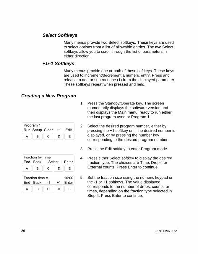
Select Softkeys Many menus provide two Select softkeys. These keys are used to select options from a list of allowable entries. The two Select softkeys allow you to scroll through the list of parameters in either direction.
+1/-1 Softkeys Many menus provide one or both of these softkeys. These keys are used to increment/decrement a numeric entry. Press and release to add or subtract one (1) from the displayed parameter. These softkeys repeat when pressed and held.
Creating a New Program 1. Press the Standby/Operate key. The screen
momentarily displays the software version and then displays the Main menu, ready to run either the last program used or Program 1.
2. Select the desired program number, either by pressing the +1 softkey until the desired number is displayed, or by pressing the number key corresponding to the desired program number.
3. Press the Edit softkey to enter Program mode.
4. Press either Select softkey to display the desired fraction type. The choices are Time, Drops, or External counts. Press Enter to continue.
5. Set the fraction size using the numeric keypad or the -1 or +1 softkeys. The value displayed corresponds to the number of drops, counts, or times, depending on the fraction type selected in Step 4. Press Enter to continue.

Operation
ProStar 704 Fraction Collector 27
6. Set the Flow Delay time (in minutes:seconds) or counts using the numeric keypad or the -1 or +1 softkeys. Flow delay is used to synchronize tube changes with sample flow for precise peak cutting. Refer to page 49 for a complete definition of this feature. Press Enter to continue.
7. The ProStar 704 built-in peak separator allows you to control the collection of sample peaks based on an external detector signal level. Set the peak threshold parameter to the percentage of full-scale input signal at which you want peak collection to begin. Press the +1 or -1 softkeys until the desired percentage is displayed, or enter the peak threshold directly using the numeric keypad. Setting the threshold to 0 disables this detection mode. Refer to page 43 for a complete definition of this feature. Press Enter to continue.
8. The next screen prompts for the average width of peaks to be collected. This information is used to detect peaks based on the slope of the detector signal. Press either Select softkey until the nearest peak width is displayed. The available options are: 5, 15, and 30 seconds; 1, 2, 4, 8, 16, and 32 minutes; 1 hour. Setting the threshold to 0 disables this detection mode. Refer to page 43 for a complete definition of this feature. Press Enter to continue.
9. The ProStar 704 peak separator has three detector input voltage ranges: 1V, 100 mV, or 10 mV. Press either Select softkey until the voltage input equal to a 100% peak from your detector is displayed. Press Enter to continue.

28 03-914796-00:2
10. The next step allows you to set up to 10 different time windows during which ProStar 704 will collect fractions. Set the time for the start of Window 1 using the numeric keypad and press Enter. Set the time for the end of Window 1 using the numeric keypad and press Enter. Repeat the process for all other desired time windows. Entering 0 for both the start and end times for a window turns that window off. Entering an end time less than the start time results in an error and ProStar 704 automatically resets the end time to the start time. In addition, all time windows must be in chronological order. If a start time less than the previous window’s end time is entered, an error results and ProStar 704 automatically resets the start time to the end time of the previous window. Time windows can also be used for peak detection. Peaks which occur outside of designated time windows are ignored. When done entering window parameters, press Enter to continue.
11. The next screen allows you to choose what to do with non-peak effluent. Press either Select softkey until the desired option is displayed. The available options are: Collect (in tubes), Divert (using drain valve), and Drain. Press Enter to continue.
12. Press either Select softkey until the desired rack/collection vessel type is displayed. The available options are: 12/13 mm tubes, 16 mm tubes, 18 mm tubes, 17 mm vials, 25/28 mm vials, Micro tubes, Prep. rack, bottles, and single beaker. Press Enter to continue.
13. Type the desired last tube number to be collected using the numeric keypad. If you enter a number larger than the maximum number of tubes for the selected rack, an error results and ProStar 704 resets this parameter to the maximum number allowable for the selected tube rack. Press Enter to continue.

Operation
ProStar 704 Fraction Collector 29
14. The next screen allows you to choose the Inject action that ProStar 704 is to use during the run. Inject action is used to automatically collect the fractions of multiple samples. Press either Select softkey until the desired option is displayed. The available options are: None, Overlay, and Skip Tube. Refer to page 49 for a complete definition of this feature. Press Enter to continue.
NOTE: The following three program steps are only displayed if an external valve controller is connected to your ProStar 704 If you do not have an external valve controller connected, pressing Enter at step 14 returns to the main menu.
15. This step allows you to select an output for the first of up to 30 output events. Press either Select softkey until the desired output number is displayed. Refer to the section beginning on page 49 for a complete definition of this feature. Press Enter to continue.
16. Press either Select softkey to turn the current output event on or off. Press Enter to continue
17. Press the +1 or -1 softkeys until the desired output event time is displayed or enter the desired time directly using the numeric keypad. Press Enter to program the next output, returning to step 15. When you finish programming output events, press Enter on the first screen of a blank event to return to the Main menu.

30 03-914796-00:2
Running a Program To run a program, press the +1 or -1 softkeys until the desired program number is displayed, or enter the desired program number directly using the numeric keypad, and press the Run softkey. The selected program begins immediately.
While the program is running, the Run screen keeps you informed of the status of the run. The Run menu offers several options which allow you to pause or end the program and monitor specific program functions. The Stop softkey pauses the program; refer to “Pausing/Ending a Program” on page 31 for more information.
Press the Drain softkey to divert flow to waste immediately. If a drain valve is installed, the effluent is diverted to waste. If an anti-drip valve or no valve is installed, the drop former moves to the waste trough. The word Drain is displayed in reverse text while effluent is being diverted. Press the Drain softkey again to return the program to normal operation.
The Wdw and Peak softkeys display window and peak separation information. Use these keys to view the status of window or peak collections. During window or peak collection, Wdw/Peak is displayed in reverse text. If no windows are set, RT is displayed instead of Wdw.
When the program is complete, the screen displays the time at completion and offers you several options. Press the Run softkey to run the program again. Press the End softkey to end the program and return to the Main menu. Press the Wdw/RT softkey to display the elapsed time since the beginning of the program. Press the View softkey to examine the contents of the current program.
Operation
ProStar 704 Fraction Collector 31
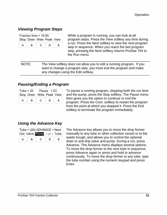
Viewing Program Steps
While a program is running, you can look at all program steps. Press the View softkey any time during a run. Press the Next softkey to view the next program step in sequence. When you reach the last program step, pressing the Next softkey returns ProStar 704 to the Run menu.
NOTE: The View softkey does not allow you to edit a running program. If you want to change a program step, you must end the program and make any changes using the Edit softkey.
Pausing/Ending a Program
To pause a running program, stopping both the run time and the pump, press the Stop softkey. The Pause menu then gives you the option to continue or end the program. Press the Cont. softkey to restart the program from the point at which you stopped it. Press the End softkey to terminate the program immediately.
Using the Advance Key
The Advance key allows you to move the drop former manually to any tube or other collection vessel or to the waste trough, and allows you to control the optional drain or anti-drip valve and pump. During a run, press Advance. The Advance menu displays several options. To move the drop former to the next tube in sequence, press Advance again or press and hold to advance continuously. To move the drop former to any tube, type the tube number using the numeric keypad and press Enter.

32 03-914796-00:2
You can also press the arrows softkey, which displays a new menu of directional arrows. Press the softkey corresponding to the desired direction of movement for the drop former. The display keeps you informed of the current tube number. When done using the directional softkeys, press the End softkey.
To move the drop former to the park position over the waste drain, press the Park softkey. The drop former moves immediately to the park position. Notice that the function of softkey E changes from Park to Tube. If you press the Tube softkey, the drop former moves to the tube number displayed.
The Advance menu clears four seconds after you last press a key and returns to the menu you were using before pressing Advance.
For complete information on all Advance menu options, refer to the Software Reference section beginning on page 51.
Clearing a Program
To remove a program from memory, press the Clear softkey on the Main menu. Press either Select softkey until Clear Program to Default is displayed. Press Enter to clear the program. Note that you can also use this feature to copy another program to the current program number. Complete information on the Clear softkey appears on page 51 .
Sample Programs This section describes four basic collection programs—fraction by time, fraction by drop count, peak detection—with step-by-step programming instructions. While these sample programs are not intended to match exactly your collection needs, they do provide you with examples of how to program some common collection routines which you can modify or combine to suit your collection needs. If you are new to ProStar 704, you may also enter these programs to familiarize yourself with the process of programming the instrument.

Operation
ProStar 704 Fraction Collector 33
Entering a Fraction by Time Program Program parameters: 10 fractions 10 seconds per fraction collected in 18 mm tubes flow delay 2 seconds This program will be saved as program number 1.
Press 1 on the numeric keypad or press the +1 softkey until Program 1 is displayed. Clear the program to its default values as explained on page 32 before continuing.
Press the Edit softkey.
Press either Select softkey to display Fraction by Time; press Enter.
To enter Fraction time = 0:10, press 1, 0; press Enter.
To enter Flow delay = 0:02, press 2; press Enter.

34 03-914796-00:2
Press Enter 6 times in succession to skip past the peak detection and time window screens.
Press either Select softkey to set Rack type = 18 mm tubes; press Enter.
To set Last tube = 10, press 1, 0; press Enter.
Press Enter to select Inject action = None.
The sample program is now ready to run. The ProStar 704 displays the Main menu. Press the Run softkey to run the sample program you just entered. Notice the new menu options displayed while the program is running. The Run menu options are described on page 30.
Entering a Fraction by Drops Program Program Parameters: 40 fractions 24 drops per fraction collected in 12/13 mm tubes flow delay of 5 seconds This program will be saved as program number 2.

Operation
ProStar 704 Fraction Collector 35
Press 2 on the numeric keypad or press the +1 softkey until Program 2 is displayed. Clear the program to its default values as explained on page 32 before continuing.
Press the Edit softkey.
Press either Select softkey to display Fraction by Drops; press Enter.
To set Fraction drops = 24, press 2, 4; press Enter.
To set Flow delay = 0:05, press 5; press Enter.
Press Enter 6 times in succession to skip past the peak detection and time window screens.

36 03-914796-00:2
Press either Select softkey to set Rack type = 12/13 mm tubes; press Enter.
To set Last tube = 40, press 4, 0; press Enter.
Press Enter to select Inject action = None.
The sample program is now ready to run. The ProStar 704 displays the Main menu. Press the Run softkey to run the sample program you just entered. Notice the new menu options displayed while the program is running. The Run menu options are described on page 30.
Entering a Peak Detect Program Program Parameters: fraction size 4 minutes (maximum fraction size/tube) 25 fractions collected in 17 mm vials flow delay 30 seconds peak threshold 35% (level sensing) average peak width 1 minute (slope detection) 100% detector signal = 1V non-peak diverted to waste This program is saved as number 3.
Operation
ProStar 704 Fraction Collector 37
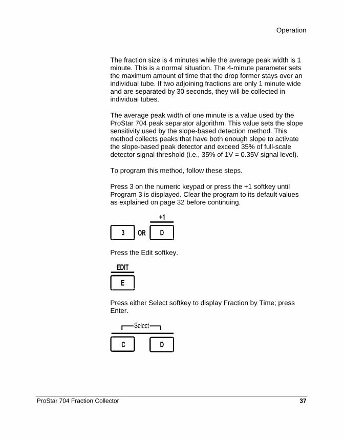
The fraction size is 4 minutes while the average peak width is 1 minute. This is a normal situation. The 4-minute parameter sets the maximum amount of time that the drop former stays over an individual tube. If two adjoining fractions are only 1 minute wide and are separated by 30 seconds, they will be collected in individual tubes.
The average peak width of one minute is a value used by the ProStar 704 peak separator algorithm. This value sets the slope sensitivity used by the slope-based detection method. This method collects peaks that have both enough slope to activate the slope-based peak detector and exceed 35% of full-scale detector signal threshold (i.e., 35% of 1V = 0.35V signal level).
To program this method, follow these steps.
Press 3 on the numeric keypad or press the +1 softkey until Program 3 is displayed. Clear the program to its default values as explained on page 32 before continuing.
Press the Edit softkey.
Press either Select softkey to display Fraction by Time; press Enter.

38 03-914796-00:2
To set Fraction time = 4:00, press 4, 0, 0; press Enter.
To set Flow delay = 0:30, press 3, 0; press Enter.
To set Peak threshold = 35%, press 3, 5; press Enter.
To set the peak width to 1 minute, press either Select softkey until Peak width = 1 minute is displayed; press Enter.
Press Enter to select Detector signal (100%) = 1 V.
Press Enter twice to bypass the window settings.

Operation
ProStar 704 Fraction Collector 39
Press either Select softkey to display Non-peak/window = Divert; press Enter.
Press either Select softkey to display Rack type = 17 mm vials; press Enter.
To set Last tube = 25, press 2, 5; press Enter.
Press Enter to select Inject action = None.
The sample program is now ready to run. The ProStar 704 displays the Main menu. Press the Run softkey to run the sample program you just entered. Notice the new menu options displayed while the program is running. The Run menu options are described on page 30.
40 03-914796-00:2
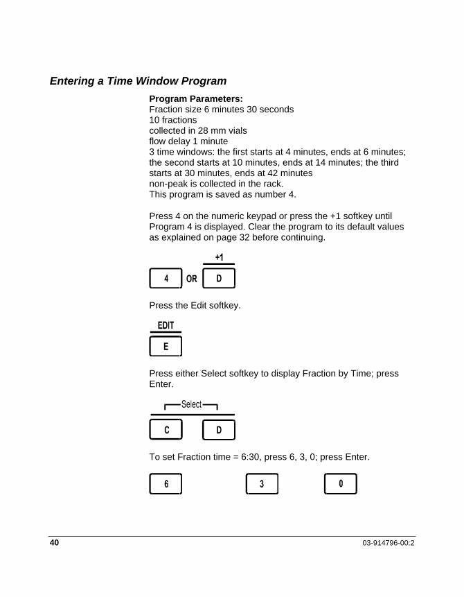
Entering a Time Window Program Program Parameters: Fraction size 6 minutes 30 seconds 10 fractions collected in 28 mm vials flow delay 1 minute 3 time windows: the first starts at 4 minutes, ends at 6 minutes; the second starts at 10 minutes, ends at 14 minutes; the third starts at 30 minutes, ends at 42 minutes non-peak is collected in the rack. This program is saved as number 4.
Press 4 on the numeric keypad or press the +1 softkey until Program 4 is displayed. Clear the program to its default values as explained on page 32 before continuing.
Press the Edit softkey.
Press either Select softkey to display Fraction by Time; press Enter.
To set Fraction time = 6:30, press 6, 3, 0; press Enter.

Operation
ProStar 704 Fraction Collector 41
To set Flow delay = 1:00, press 1, 0, 0; press Enter.
Press Enter three times to bypass the Peak threshold, Peak width, and Detector Signal parameters.
NOTE: You can combine peak detection with time windows in your programs. Refer to the Peak Detection program example on page 36 for peak detection parameter examples.
To set Window 1 start = 4:00, press 4, 0, 0; press Enter.
To set Window 1 end = 6:00, press 6, 0, 0; press Enter.
To set Window 2 start = 10:00, press 1, 0, 0, 0; press Enter.
To set Window 2 end = 14:00, press 1, 4, 0, 0; press Enter.

42 03-914796-00:2
To set Window 3 start = 30:00, press 3, 0, 0, 0; press Enter.
To set Window 3 end = 42:00, press 4, 2, 0, 0; press Enter.
Now that the three desired windows have been programmed, press Enter to select Window 4 start = 0:00 = Off and move to the next step.
Press either Select softkey to display Non-peak/window = Collect; press Enter.
Press either Select softkey to display Rack type = 25/28 mm vials; press Enter.
To set Last tube = 10, press 1, 0; press Enter.

Operation
ProStar 704 Fraction Collector 43
To select Inject action = None, press Enter.
The sample program is now ready to run. The ProStar 704 displays the Main menu. Press the Run softkey to run the sample program you just entered. Notice the new menu options displayed while the program is running. The Run menu options are described on page 30.
Peak Separator and Time Windows The ProStar 704 slope-based peak separator is used with a detection instrument to control the collection of sample peaks. The detection instrument can be a UV absorbance detector, fluorometer, or any instrument that produces analog voltage output signals. ProStar 704 differentiates each peak, which it then collects in the designated tube or other collection vessel. All non-peak effluent is diverted to a separate tube, collection vessel, or waste as programmed.
The peak separator responds to the slope change characteristics of positive-direction sample peaks and uses that information to initiate collection tube and/or void volume changes. This allows baseline-independent collection of large or small magnitude peaks as well as the detection of partially resolved peaks. The user-selectable flow delay, explained on page 49, compensates for the time the sample takes to travel from the detector to ProStar 704 for accurate collection of true peak fractions.
The ProStar 704 peak separator has three user-selectable detector input voltage ranges for 100% peak signal: 1 V, 100

44 03-914796-00:2
mV, or 10 mV. Choose the input voltage which corresponds to your detection device.
Level Sensing The ProStar 704 allows you to collect fractions by level sensing, which collects only that part of the peak which rises above the user-selectable peak threshold parameter. This type of peak separation allows you to collect only the most concentrated portion of each peak. Collection of peaks begins only when the signal exceeds the peak threshold value. If a peak does not reach the peak threshold, it is not collected. An example of this type of collection is shown in Figure 13.
Figure 13 Level Sensing Collection

Operation
ProStar 704 Fraction Collector 45
Slope Detection Slope detection allows peak separation based on the change in the slope of the signal over a wide range of user-selectable average peak widths, as measured at the baseline. The available ranges of average peak widths are: 5, 15, and 30 seconds; 1, 2, 4, 8, 16, and 32 minutes; and 1 hour. The ProStar 704 slope detector can detect peak with widths ranging from 0.2 to 2 times the programmed setting. For best results, set the peak width to just over the average peak width being separated. For example, if the average peak width is 45 seconds, select 1 minute peak width when programming the fraction collection. An example of this type of collection is shown in Figure 14.
Figure 14 Peak Detector Collection

46 03-914796-00:2
Slope Detection and Level Sensing Slope detection can be used with level sensing. When both of these parameters are set in a collection program, a peak will be collected only when it meets both the peak threshold and slope criteria. Combining these two parameters allows you to collect only the most concentrated segment of each peak.
Time Windows The ProStar 704 time windows programming allows you to set portions of the program, based on running time, during which samples are collected. Time windows can be used for several different applications. They can be used to reject peaks which are of no interest to you, to cut peaks in order to increase the concentration of the desired sample, to divert initial waste volume, or to allow you to set up discrete collection periods for specific collection vessels. An example of this type of collection is shown in Figure 15.

Operation
ProStar 704 Fraction Collector 47
Figure 15 Time Windows Collection
You can combine time windows with slope detection or level sensing, or all three can be combined to create very specific collection routines. When combining either or both of the peak detection schemes with time windows, all of the programmed criteria must be met before ProStar 704 collects a sample—the peak must meet the criteria for peak threshold and the peak must occur during a time window.

48 03-914796-00:2
Figure 16 Time Windows/Level Sensing
Operation
ProStar 704 Fraction Collector 49
Flow Delay, Outputs, Inject Action, Valve and Pump Control ProStar 704 includes these advanced features to give you the greatest versatility and functionality for your fraction collection needs. This section contains a complete description of each of these features.
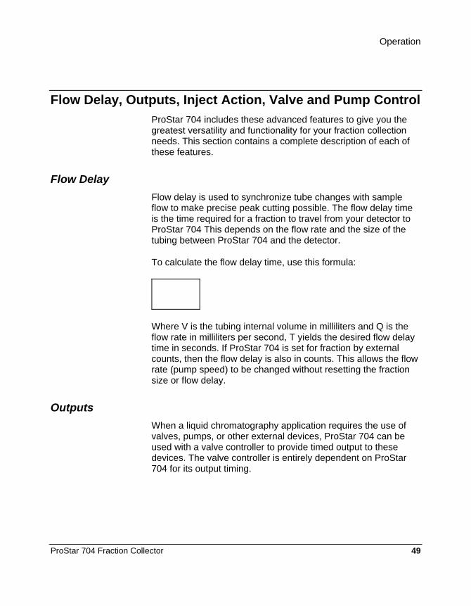
Flow Delay Flow delay is used to synchronize tube changes with sample flow to make precise peak cutting possible. The flow delay time is the time required for a fraction to travel from your detector to ProStar 704 This depends on the flow rate and the size of the tubing between ProStar 704 and the detector.
To calculate the flow delay time, use this formula:
Where V is the tubing internal volume in milliliters and Q is the flow rate in milliliters per second, T yields the desired flow delay time in seconds. If ProStar 704 is set for fraction by external counts, then the flow delay is also in counts. This allows the flow rate (pump speed) to be changed without resetting the fraction size or flow delay.
Outputs When a liquid chromatography application requires the use of valves, pumps, or other external devices, ProStar 704 can be used with a valve controller to provide timed output to these devices. The valve controller is entirely dependent on ProStar 704 for its output timing.
50 03-914796-00:2
Inject Action The ProStar 704 can control up to 8 different output devices and 30 output events through the valve controller. Programming outputs are explained in the sections beginning on page 32 and page 51.
Inject action is used to automatically collect the fractions of multiple samples. If Inject action is set to Overlay, the fractions are collected repeatedly in the same tubes. If set to Skip tube, the fractions are collected in new tubes with one tube left empty as a marker between each set of fractions.
When a run that uses an Inject action begins, ProStar 704 waits for the first inject signal before executing the programmed run sequence. Thereafter, anytime another inject occurs, the run sequence starts over, either from the initial tube for Overlay, or two tubes ahead for Skip tube.
The inject signal is applied to pin 4 of the Detector connector as a momentary contact closure to circuit common (pin 8) or TTL low pulse.
Valve and Pump Control ProStar 704 can be used with either an anti-drip or a drain valve and can also control an external pump. When the drop former is in the Park position over the waste trough, the anti-drip or drain valve is open. When the arm is moving between tubes, ProStar 704 closes the anti-drip valve, blocking flow until the next tube position is reached. In the case of a drain valve, ProStar 704 diverts flow to the waste line between tubes. The pump is normally off except during a run. For quick reacting pumps, ProStar 704 can be configured to stop the pump while moving the drop former. When a run is started, the pump is enabled and the valve (if present) is opened.
If you press the Stop softkey, the pump is turned off and valve remains as it was when you pressed Stop. If you press the Drain softkey during a run, the drain valve diverts flow to the waste line. If you have an anti-drip valve or no valve, the drop former
Operation
ProStar 704 Fraction Collector 51
moves to the waste trough until you press the Drain softkey again. In all cases, the pump remains active.
You can also control valve and pump output manually by pressing Advance. If they are active, Valve and Pump are displayed in reverse text. These softkeys operate like toggle switches, turning the valve or pump on or off depending on the current state. If you turn off the valve during a collection, the collection timer or drop counter holds at the last value until you turn the valve back on and continue collecting the sample. See Key Definitions, page 51, for information on using the Advance key.
Software Reference This section is a reference to the ProStar 704 software.
Key Definitions This section contains key and softkey definitions.
Standby/Operate This key turns ProStar 704 on and off. When you turn on the ProStar 704, the drop former moves to the park position if it is not already there.
Numeric Keypad The numeric keypad is used to enter numbers directly, for example, when called for in a program step or to move to a specific tube.
Softkeys The softkeys are the five keys under the LCD labeled A through E. The function of each softkey varies depending on the ProStar 704 function at a given time. The function of each ProStar 704 softkey is explained in detail in the next section.

52 03-914796-00:2
Advance
The basic function of the Advance key is to move the drop former to the next tube or collection vessel in sequence. Pressing Advance also displays the Advance menu, which provides access to output, valve, and pump control, as well as drop former positioning control.
To advance to the next tube in sequence, press Advance to display the Advance menu, then press Advance again. The drop former moves to the next tube immediately. Press and hold Advance to move the drop former continuously. If you are using a drain valve, flow is routed to waste between tubes. If you are using an anti-drip valve, flow is halted between tubes. You can also enter a tube number directly using the numeric keypad. When you press Enter, the drop former moves to the selected tube immediately.
After four seconds without pressing a key, the Advance menu clears and the Run menu is displayed.
Advance Menu Options The Advance menu gives you access to several manual control features. Each softkey function is described below.
Out (Output Menu)
The Out softkey manually turns the outputs of a connected valve controller on or off. When the Out softkey is pressed, the Output menu is displayed.
End Returns ProStar 704 to the Advance menu.
Back Returns ProStar 704 to the Advance menu.

Operation
ProStar 704 Fraction Collector 53
Select Allows you to select which of the eight outputs to turn on or off.
On/Off Toggles the selected output on or off depending on its current state.
Valve
The Valve softkey allows you to control manually the operation of the optional anti-drip or drain valve. When Valve is displayed in reverse text, the valve is directing flow to the tube. The Valve softkey toggles flow from the valve to the tube on or off depending on its current state.
Pump
The Pump softkey allows you to manually control the operation of the pump connected to ProStar 704. When Pump is displayed in reverse text, the pump is on. The Pump softkey toggles the pump on or off depending on its current state.
Directional Arrows
The directional arrows softkey allows you to move the drop former to any tube or collection vessel. Press the directional arrows softkey to display the Direction menu. Press the softkey labeled with the arrow which points in the desired direction of drop former movement. Press and hold a softkey for repeated movement. The display indicates the current tube number. Press the End softkey to return to the Advance menu.
54 03-914796-00:2
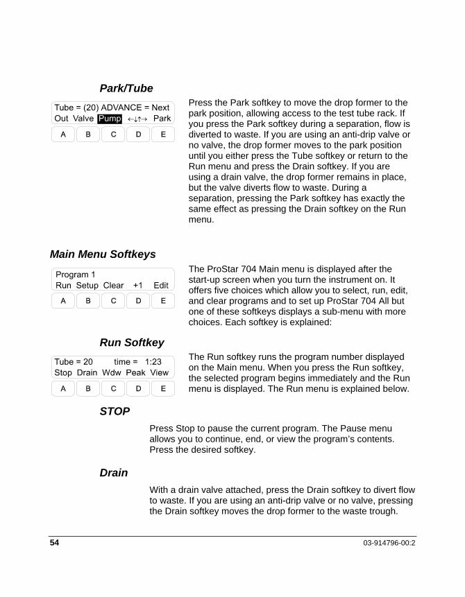
Park/Tube
Press the Park softkey to move the drop former to the park position, allowing access to the test tube rack. If you press the Park softkey during a separation, flow is diverted to waste. If you are using an anti-drip valve or no valve, the drop former moves to the park position until you either press the Tube softkey or return to the Run menu and press the Drain softkey. If you are using a drain valve, the drop former remains in place, but the valve diverts flow to waste. During a separation, pressing the Park softkey has exactly the same effect as pressing the Drain softkey on the Run menu.
Main Menu Softkeys
The ProStar 704 Main menu is displayed after the start-up screen when you turn the instrument on. It offers five choices which allow you to select, run, edit, and clear programs and to set up ProStar 704 All but one of these softkeys displays a sub-menu with more choices. Each softkey is explained:
Run Softkey
The Run softkey runs the program number displayed on the Main menu. When you press the Run softkey, the selected program begins immediately and the Run menu is displayed. The Run menu is explained below.
STOP Press Stop to pause the current program. The Pause menu allows you to continue, end, or view the program’s contents. Press the desired softkey.
Drain With a drain valve attached, press the Drain softkey to divert flow to waste. If you are using an anti-drip valve or no valve, pressing the Drain softkey moves the drop former to the waste trough.
Operation
ProStar 704 Fraction Collector 55
While flow is being diverted or sent to the waste drain, Drain is displayed in reverse text.
RT/Wdw If the program currently running uses no time windows, this softkey is labeled RT (run time); if it has one or more time windows programmed, this softkey is labeled Wdw. Press this softkey to display the running time or window time. During a time window, this softkey is displayed in reverse text. Press this softkey again or press the Back softkey to return to the Run menu.
Peak If the current program uses no peak detection, this softkey is unlabeled. For programs which do use peak detection, press this softkey to display the level and slope peak detection characteristics. During a peak, this softkey is displayed in reverse text. Press this softkey again or press the Back softkey to return to the Run menu.
View Press the View softkey to display the parameters of the program currently running. Note that you cannot change any program parameters while a program is running.
Setup Softkey
This softkey provides access to ProStar 704 setup routines through the Setup menu. The function of the each softkey on the Setup menu is explained below.
End Pressing this softkey exits the Setup menu and returns ProStar 704 to the Main menu.

56 03-914796-00:2
Config
This softkey displays a menu providing a series of choices which allow you to configure ProStar 704 options. Press either Select softkey to display the desired option. Press Enter to continue to the next configuration option. Press the Back softkey to return to the previous screen. Press the End softkey to leave Configuration mode and return to the Setup menu. The available options are listed below with defaults shown in bold type.
Pump Off: End of run only; End + when moving
If you are using a pump which can react quickly to the pump control output, you may set this parameter to stop the pump whenever the drop former is moving to reduce the chance of drops missing a tube. This is also useful with an anti-drip valve to reduce the pressure on the valve between tubes.
Serial Mode: Off; Text only; DASNET
Motor Acceleration: 0 - 225; default = 5
This parameter is set at the factory to a conservative 5 to prevent flinging drops. If you are using drop counting at low rates, drop counting with a valve, large collection vessels, or errant drops are not a concern, you may increase this setting to decrease significantly the tube-to-tube time. Settings above 30 may result in position errors depending on the tubing load, etc.
Display Contrast: 0 - 9; default = 2
Adjustable to suit personal preference.
Audio Level: 0-9; default = 9
Adjustable to suit personal preference.
Cal This softkey provides access to the ProStar 704 calibration.

Operation
ProStar 704 Fraction Collector 57
Info The Info softkey displays technical information from the ProStar 704 which may be needed when talking with a Varian service representative.
Test The Test softkey allows you to test various functions using ProStar 704 built-in self-diagnostic routines.
Clear Softkey The Clear softkey allows you to clear the current program from memory by resetting all program parameters to their default values. It also allows you to copy another program to the current program number. This feature is very useful if you want to modify an existing program or want to rearrange the order of programs in memory.
IMPORTANT: Clearing a program or copying another program to the current program number removes the current program from memory. Once a program is cleared or copied over, it cannot be restored but must be reprogrammed from the start.
To Clear a Program To clear the current program to the default values, select the program you want to clear on the Main menu, press the Clear softkey, press either Select softkey until Clear program to Default is displayed, and press Enter to clear.
To Copy a Program To copy another program to the current program number, first select the program to copy to on the Main menu. Next, press the Clear softkey, press either Select softkey until the desired program number to copy from is displayed. Press Enter to copy the selected program. You may also use the numeric keypad to enter the number of the program you want to copy from.

58 03-914796-00:2
For example, if you want to copy Program 4 to Program 2, press 2 on the numeric keypad or press the +1 softkey until Program 2 is displayed. Then press the Clear softkey. Press either Select softkey until Copy from Program 4 is displayed. You may also press 4 on the numeric keypad to select Program 4. To complete the copy process, press Enter.
+1 Softkey This softkey selects the next program number in sequence. You can also load the desired program by pressing the appropriate number key.
Edit Softkey The Edit softkey allows you to program/edit the selected program. Instructions for programming ProStar 704 appear on page 26. This section outlines the range of choices available for each programming step, with the default values shown in bold type.
Number of programs: 9
Fraction types: Time, Drops, External count.
Fraction size: Drops and Counts = 1 to 999,999; Time = 1 second to 99h:59m:59s
Flow Delay: Drops and Counts = 0 to 999,999; Time = 0 seconds to 99h:59m:59s
Peak Threshold: 0 = None; 1% - 99%
Peak Width: No Slope Detect, 5 seconds, 15 seconds, 30 seconds, 1 minute, 2 minutes, 4 minutes, 8 minutes, 16 minutes, 32 minutes, 1 hour

Operation
ProStar 704 Fraction Collector 59
Detector Signal: 1V, 100 mV, 10 mV
Window: 1 = 0:00 = Off (start = end); 0:01 to 99h:59m:59s; up to 10 windows
Non-Peak/Window: Collect, Divert, Drain
Rack type: 12/13 mm tubes, 16 mm tubes, 18 mm tubes, 17 mm vials, 25/28 mm vials, Micro tubes, Prep. rack, Bottles, Single beaker
Last Tube: 1 to maximum for Rack Type selected.
Inject Action: None, Overlay, Skip tube
With optional valve controller attached only
Event: 00 = None; Output 1 to 8, up to 30 output events
Output: 0 = Off; On
Event Time: 00:00:00; to 99h:59m:59s

60 03-914796-00:2

ProStar 704 Fraction Collector 61
Maintenance and Repair Introduction
The ProStar 704 has been designed to be easy to maintain and to repair by the customer. This section provides detailed instructions for maintenance, troubleshooting, and repair of your ProStar 704 Fraction Collector. If you are unsure how to proceed with a repair procedure, do not hesitate to call Varian’s LC Technical Service Department at 1-800-FOR-HPLC.
LC Technical Service Department If you have a problem with the instrument or need replacement parts information, contact LC Technical Services. If you write or send a FAX, include all information on problems experienced with the instrument. Send written requests for information to:
Varian, Inc. 2700 Mitchell Drive Walnut Creek, California 94598-1675 Attention: Customer Service Phone (925) 939-2400
Please call the LC Technical Services Department before returning the instrument to the factory for repair. Problems can frequently be solved in the field with help from our experienced service technicians.
Before returning the instrument, call LC Technical Services for an RMA number. When you have a RMA Number, make sure all parts are in their proper place, then pack the instrument. Wrap the instrument in heavy paper or put it in a plastic bag for protection. Pack the instrument in its original shipping container with the original packing material. If the original shipping container is not available, place the instrument in a strong cardboard box at least six inches larger in all three dimensions than the instrument. Fill the box around the instrument with a resilient packing material—shredded paper, bubble pack,

62 03-914796-00:2
expanded foam, etc. Seal the box with strapping tape or other shipping tape and ship it to the address given above.
It is very important that the instrument be well packed for shipment and fully insured. Damage in shipment due to inadequate packing can delay the repair and return of the instrument to you. Damage in transit is the responsibility of the carrier, and any claims must be made directly with the carrier.
This section helps you isolate and solve instrument problems quickly. Locate the problem you are experiencing and follow the remedies one at a time and in order. If the problem you are experiencing is not listed or does not respond to the recommended solutions, write a summary of the problem and all steps you have taken to correct it and call or write Varian’s Service Department.
Disassembly and Repair Follow the instructions contained in this section for normal maintenance and to repair common problems.
Cleaning the Drip Tray To clean the drip tray, remove it from the instrument. The drip tray is held in place by pins at each corner. Remove the test tube rack, turn the instrument on its side, and remove the waste tube from the drip tray. Set the instrument on its feet and pry the corners of the drip tray with your fingers. After loosening all four corners, lift the drip tray up and off the instrument case. Clean the drip tray with mild detergent.
Cleaning the Drop Counter Sleeve The drop counter sleeve is a glass cylinder which lines the inside of the drop counter assembly to protect the photosensors from effluent. The drop counter sleeve is attached to the drop former. In order for ProStar 704 to operate reliably, this sleeve should be removed and cleaned periodically. No special tools are required for this procedure.

Maintenance and Repair
ProStar 704 Fraction Collector 63
To Remove the Drop Former
Using the Advance key, position the drop counter at the front end of the arm. Place the drop counter over tube position 1.
Carefully remove the drop former by pulling it straight up and out of the drop counter assembly while holding the arm and drop counter in place with your other hand. Twisting the drop counter slightly makes removal easier.
NOTE: Support the drop counter at the points indicated in Figure 17 while removing the drop former assembly.
1 Support drop counter here
Figure 17 Remove Drop Former
Wash the sleeve with a suitable detergent and solvent to remove all traces of effluent or other contamination. Dry the sleeve completely. After cleaning, avoid touching the sleeve.

64 03-914796-00:2
To Install the Drop Former
To install the drop former, align the drop former in the drop counter assembly and gently press the drop former into the drop counter assembly. Support the underside of drop counter assembly while pressing the drop former into place. Twisting the drop former slightly makes it easier to install.
Removing the Upper Case Back Panel Unlock the locking cams by rotating them up and remove the three screws and inter-locking bolt located on the back of the upper case back panel as shown in Figure 18.
1 Knob 2 Case back retaining brackets 3 Locking cams (unlocked) 4 Interlocking bolt 5 Upper case back screws
Figure 18 Upper Case Back Screws, Interlock Bolt

Maintenance and Repair
ProStar 704 Fraction Collector 65
Grasp the knob at the top of the upper case back panel and gently but firmly pull back until the top edge of the upper case back panel just clears the upper case, then lift the back panel off of the upper case half. The back panel must slide up approximately 1/4" and off of the retaining brackets.
NOTE: A flat-blade screwdriver may be inserted into the screwdriver slot to pry out the top of the upper case back panel.
IMPORTANT: Remove the upper case back carefully. The retaining brackets may snap off if subjected to excessive stress.
To reinstall the upper case back panel, follow these steps in reverse order.
Separating the Case Halves and Removing the Lower Case Back Panel
To access the ProStar 704 internal parts, it is necessary to remove the back panels from the upper and/or lower case halves. Follow these instructions carefully.
Lay the instrument on its side and remove the two case screws on the bottom of the instrument as shown in Figure 19.

66 03-914796-00:2
1 Case bottom screws
Figure 19 Remove case bottom screws
Set the instrument back on its feet. Remove the upper case back panel as described on page 64.
Lift the upper case off of the lower case. Tip the upper case forward, allowing it to rest on the lower case and test tube rack.
Lift the lower case back panel up about one-half inch to release it from its retainers and tip it back, allowing it to rest on the bench top.
NOTE: If you want to leave the upper case half cables attached for troubleshooting purposes, stop here. Replace the upper case half in its normal position, without the upper case back panel. The instrument should now appear as shown in the right-hand drawing in Figure 20.

Maintenance and Repair
ProStar 704 Fraction Collector 67
1 Knob 2 Locking cams 3 Keyboard cable 4 Rolling cable 5 Display cable 6 Interlocking bolt 7 Lift upper case half off lower case half 8 Interior shield 9 Tape and ribbon cables 10 Lower case back and circuit board 11 Left-to-right motor cable 12 Display module
Figure 20 Cable Locations on Circuit Boards, Case Disassembly
Disconnect the four cables linking the upper and lower case halves. Refer to the section on Interconnect Cable Connections on page 68, for complete instructions.
You can now set the upper case half aside.
Depress the retainers on the standoffs at the top of the front circuit board and tip the circuit board slightly toward the back and off the standoffs. Lift the front circuit board and lower case back

68 03-914796-00:2
panel assembly out of the lower case. Both circuit boards are now detached.
To reassemble the case halves, follow these steps in reverse order.
NOTE: The ribbon cable connectors have an indexing mark—a small raised triangle or other mark—molded into the connector housing. Align this mark with pin 1 of the pin connector as indicated on the circuit board assembly.
Interconnect Cable Connections Several cables link the upper and lower case halves. All cables are equipped with connectors to facilitate disassembly. When performing any servicing which requires separating the case halves, disconnect only those cables necessary and use masking tape and a marker to mark each cable and its associated connector in the lower case half. Marking the cables and connectors can save you time and trouble when reassembling the instrument.
Remove the upper case half and then the lower case back panel as described on page 65.
Disconnect the keyboard, rolling, and motor cables indicated in Figure 20 to separate the case halves.
To disconnect the display cable, you must unlock the snaps at either side of the cable connector. As you press the snaps outward, the cable connector is freed from the CBA connector.
To reattach the cables, follow these steps in reverse order.
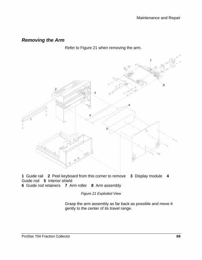
Maintenance and Repair
ProStar 704 Fraction Collector 69
Removing the Arm Refer to Figure 21 when removing the arm.
1 Guide rail 2 Peel keyboard from this corner to remove 3 Display module 4 Guide rod 5 Interior shield 6 Guide rod retainers 7 Arm roller 8 Arm assembly
Figure 21 Exploded View
Grasp the arm assembly as far back as possible and move it gently to the center of its travel range.

70 03-914796-00:2
Remove the upper case back panel as described on page 64. Disconnect the ribbon cable connectors from the main circuit board in the lower case half as described on page 68.
The ribbon cables from the LCD and keyboard are taped to the interior shield as shown in Figure 20. Remove this tape from the interior shield before removing the shield.
Remove the interior shield by sliding it out the back of the instrument. Remove the waste trough.
Loosen the timing belt idler screws and move the idler toward the left-to-right motor. Remove the timing belt from the idler and left-to-right motor pulleys as shown in Figure 22.
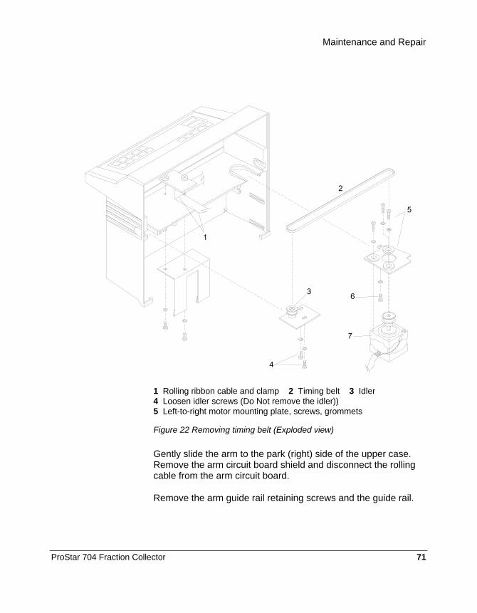
Maintenance and Repair
ProStar 704 Fraction Collector 71
1 Rolling ribbon cable and clamp 2 Timing belt 3 Idler 4 Loosen idler screws (Do Not remove the idler)) 5 Left-to-right motor mounting plate, screws, grommets
Figure 22 Removing timing belt (Exploded view)
Gently slide the arm to the park (right) side of the upper case. Remove the arm circuit board shield and disconnect the rolling cable from the arm circuit board.
Remove the arm guide rail retaining screws and the guide rail.

72 03-914796-00:2
Use a small flat-blade screwdriver or small needle-nose pliers to remove the guide rod retainers from the slots in the upper case. Using the screwdriver, carefully lift on edge of one retainer and pull it toward the rear of the slot. Repeat this procedure until you have removed both retainers from the slots in the case.
Remove the end of the guide rod furthest from the arm by carefully pulling it out of the case. Slide the guide rod out of the arm assembly and set it aside. The roller on the arm assembly may fall off as you remove the guide rod. Be careful not to lose the roller.
The arm assembly is now disconnected. Remove it by carefully pulling it out the back of the upper case half. The left-to-right stop plate in the upper case half may catch on the home position sensor on the arm circuit board. Be very careful when removing the arm assembly to avoid damaging the home position sensor.
Installing the Arm Refer to Figure 21 when installing the arm.
Slide the guide rod through the arm assembly and center it on the arm.
Carefully slide the arm assembly through the slot in the upper case half and position the guide rod in its retaining slots. Be sure the timing belt is roughly in place and is not folded.
Slide the guide rail through the arm assembly. Be sure the roller is properly positioned and able to move freely.
Slide the guide rail into the upper case half and install its retaining screws. The front edge of the guide rail must be snug against the upper case before installing the retaining screws.
Install guide rod retainer clips by positioning each one with needle-nose pliers. Next, press the retainers into place against the guide rod. The retainers must keep the guide rod from moving.

Maintenance and Repair
ProStar 704 Fraction Collector 73
Connect the rolling cable connector to the arm circuit board and install the arm circuit board shield and retaining screws.
Route the timing belt around the motor pulley and idler. Slide the idler assembly away from the motor to apply tension to the timing belt. Tighten the idler assembly retaining screws.
CAUTION
Do not overtighten the idler assembly retaining screws.
The timing belt should be tight enough that it does not slip when moving the arm by hand, but not so tight that the timing belt pulls the left-to-right motor assembly out of position. If the timing belt is not properly tensioned, the arm will chatter as it moves left to right and may miss test tubes.
Install the interior shield. The front edge of the shield slides into the slots molded into the upper case half. The lower edge of the interior shield rests on the ledge of the upper case half.
Install the waste trough.
Lay the ribbon cables from the display and keyboard smoothly along the back of the interior shield. Secure the cables in place with the tape removed earlier.
Reattach the upper and lower case halves and upper case back panel as described on page 64 and on page 65.
Replacing the Keyboard The keyboard is an integral part of the front panel label which is secured to the upper case half with an adhesive. Refer to Figure 21 when performing this procedure.
Remove the upper case as described on page 65.
Remove the interior shield as described on page 69.
74 03-914796-00:2
Set the upper case half on its back.
Gently lift the label at its lower left corner and slowly peel it toward the top until it is free from the case, as shown in Figure 21. Gently pull the keyboard ribbon cable through the slot in the case. The cable connector may become caught on the slot. Setting the upper case on its side allows you to guide the connector through the slot more easily.
Remove any excess adhesive from the case.
The clear display window on the keyboard has a thin protective layer of plastic covering its back side. Remove this protective plastic before installing the keyboard by pressing a piece of tape on one end of the window and pulling it off.
To Install a New Keyboard
Remove the backing from the keyboard to expose the adhesive.
Insert the keyboard ribbon cable connector through the slot in the upper case front panel.
Hold the upper portion of the keyboard panel, with the window, over the top of the keyboard panel while positioning the lower panel.
Align the keyboard to the top edge of the keyboard area on the front panel of the upper case. Gently lower the keyboard into place from top to bottom. Be careful to prevent air pockets from forming under keyboard/label, by rolling the keyboard/label into position from one edge.
Check the alignment and position of the keyboard label and then firmly press it into place.
Reinstall the interior shield as described on page 69. Tape the ribbon cables into place on the interior shield.
Reattach the upper and lower case halves as described on page 65.

Maintenance and Repair
ProStar 704 Fraction Collector 75
Reinstall the upper case back panel as described on page 64. The ribbon cable connectors have an indexing mark—a small raised triangle—molded into the connector housing. Align this mark with pin 1 of the pin connector as indicated on the circuit board.
Replacing the Liquid Crystal Display To Remove the Display
Remove the upper case half as described on page 65.
Disconnect all interconnect cables as described on page 68.
Lay the upper case on its side. Remove the interior shield as described on page 69.
Remove the four mounting screws from the corners of the display module.
Before removing the display, notice that adhesive from the keyboard panel may be holding the display in place. Gently pry the display loose so you do not damage the keyboard and label.
Remove the display module from the upper case as shown in Figure 21.
To Install the Display
Remove the protective plastic film from the face of the new display module.
Position the new display module in the upper case, ensuring that it is right side up—check the ribbon cable orientation against Figure 20 and Figure 21.
Install the one mounting screw at each corner of the display module. Be sure that the fiber washers are installed between the display module and the case.

76 03-914796-00:2
Reinstall the interior shield and position the two ribbon cables properly over it. Tape the ribbon cables into place on the interior shield.
Reattach all cables and reattach the case halves as described on page 65.
Replacing the Left-to-Right Motor Remove the upper case half as described on page 65. Set the lower case half aside.
Remove the interior shield as described on page 69 and lay it aside. Lay the ribbon cables from the display and keyboard over the top of the upper case to keep them clear from the work area.
Loosen the two screws retaining the left-to-right motor timing belt idler assembly. Slide the idler assembly toward the stepper motor to loosen the timing belt. Remove the timing belt from the pulley attached to the left-to-right motor. Slide the arm assembly to the right side of the instrument. Refer to Figure 23
Remove the clip securing the end of the arm guide rod closest to the left-to-right motor and slide that end of the guide rod out of its mounting feature. Refer to Figure 21.
Do not remove the arm from the upper case. You will need to remove the end of the guide rod above the left-to-right motor from its slot in order for the top of the timing belt pulley to pass under the guide rod.
Remove the left-to-right motor assembly retaining screw as shown in Figure 23.

Maintenance and Repair
ProStar 704 Fraction Collector 77
1 Remove guide rod retainer from this side 2 Mounting slots 3 Loosen idler screws (Do Not remove idler) 4 Timing belt 5 Mounting plate, screws, grommets 6 Motor retaining screw
Figure 23 Replacing the Left-to-Right Motor
Slide the left-to-right motor assembly out of the slots in the upper case.
Remove the screws securing the left-to-right motor to the mounting plate and remove the mounting plate from the motor. Note the orientation of the grommets in the mounting plate.

78 03-914796-00:2
Installing the Left-Right Motor
Position the mounting plate assembly on the left-to-right motor, ensuring that the motor is properly oriented on the mounting plate assembly (not upside down) and the grommets are in place in the mounting holes. Attach the retaining screws to secure the mounting plate assembly to the left-to-right motor.
Slide the left-to-right motor-mounting plate assembly into the slots in the upper case until it reaches the mounting stops molded into the case.
Install the retaining screw in the left-to-right motor-mounting plate assembly. Do not overtighten the retaining screws.
Reinstall the arm guide rod and retaining clip.
Route the timing belt around the motor pulley and idler. Slide the idler assembly away from the motor to apply proper tension to the timing belt. Tighten the idler assembly retaining screws. Do not overtighten the retaining screws.
NOTE: The timing belt should be tight enough that it does not slip when moving the arm by hand, but not so tight that the timing belt pulls the left-to-right motor assembly out of position. If the timing belt is not properly tensioned, the arm will chatter as it moves left to right and may miss test tubes.
Reinstall the interior shield as described on page 69.
Reattach the upper and lower case halves as described on page 65.
Replacing the Arm Circuit Board The arm circuit board contains both the left-to-right and front-to-back home position sensors as well as all connectors for the arm assembly.

Maintenance and Repair
ProStar 704 Fraction Collector 79
Move the arm to the park position to provide clear access to the arm circuit board.
Remove the upper case half as described on page 65.
Lay the upper case on its side, park position down.
Remove the interior shield as described on page 69 and lay it aside.
1 Arm assembly 2 Circuit board 3 Standoffs 4 Circuit board cover 5 Cover screws
Figure 24 Removing Arm Circuit Board Hardware
Remove the two retaining screws which hold the arm circuit board shield in place. Slide the arm circuit board shield back along the rolling ribbon cable to expose the arm circuit board.
Using masking tape and a marker, mark the location of all connectors on the arm circuit board. Detach all cables from the arm circuit board.
Unscrew the two hexagonal standoffs which hold the arm circuit board in place.

80 03-914796-00:2
Slide the arm circuit board out of the arm.
Carefully install the new arm circuit board on the arm, ensuring that you do not damage any of the components on the underside of the circuit board.
NOTE: Ensure that the arm circuit board is properly oriented so it will clear the left-to-right stop.
Secure the arm circuit board in place with the two hexagonal standoffs. Do not over-tighten the standoffs. Attach all cables to the new arm circuit board and reinstall the arm circuit board shield.
Reinstall the interior shield as described on page 69.
Reattach the upper and lower case halves as described on page 65.
Replacing the Drop Counter Circuit Board Using the Advance key, position the drop counter at the front end of the arm. Carefully remove the drop former as described on page 62.
Remove the test tube rack and lay the instrument on its back.
There are two snap catches on the underside of the drop counter housing. Use a small flat-blade screwdriver to push the catches away from the arm while gently lifting the top of the drop former housing.
Open the top of the drop former housing all the way.
Gently remove the circuit board from its connectors and take it out of the housing.

Maintenance and Repair
ProStar 704 Fraction Collector 81
1 Drop former 2 Drop counter circuit board 3 Snap catches 4 Drop counter housing
Figure 25 Replacing Drop Counter Circuit Board
Position the new drop counter circuit board, making sure that the connector pins are properly aligned, and press it into place.
Close the drop counter housing over the circuit board and press firmly until the cover snaps lock it into place. When closing the drop counter housing, support the underside of the arm to prevent damage to the arm mechanism.
Place the instrument on its feet and install the drop former as described on page 62.
82 03-914796-00:2
Replacing the Front-Back Axis Drive Components Move the arm to the park position to provide clear access to the front-to-back motor.
Remove the upper case as described on page 65.
Remove the interior shield as described on page 69.
Lay the upper case on its side with the park position down.
Remove the retaining screws securing the arm circuit board shield. Slide the shield back along the rolling ribbon cable.
Detach the front-to-back motor cable from the arm circuit board.
Remove the front-to-back motor retaining screws and carefully remove the front-to-back motor from the arm assembly. Several small parts may come out when you remove the motor. Ensure that none of these parts are lost.
The front-to-back motor cam may not slide out of the planet gear bearing easily, especially if the instrument is warm. Allow the instrument to cool to room temperature, then gently lift the motor out.
Remove the slider, spacer, and planet gear from the arm assembly. Inspect the slider, planet gear bearing, and planet gear for wear. The planet gear bearing can stay in the planet gear.
Reinstall the planet gear and planet gear bearing in the arm assembly. The planet gear slides through the slot in the arm and must be positioned at the bottom of the ring gear, with its pins facing the front-to-back motor and oriented at a 45-degree angle.
Install the spacer in the arm. The straight edges on the spacer slide through the slot on the arm.

Maintenance and Repair
ProStar 704 Fraction Collector 83
1 Motor screws 2 Front-to back motor 3 Slider 4 Spacer 5 Planet gear bearing 6 Plant gear 7 Arm assembly
Figure 26 Front-to-Back Drive Assembly
NOTE: The straight edges on the spacer slide through the slot on the arm. Slide the spacer through the slot until it is pressed against the planet gear with the planet gear pins protruding through the slot in the spacer. Rotate the spacer counter-clockwise 45° until it reaches a stop. Reposition the planet gear to sit on the bottom of the ring gear with its pins oriented vertically; centered in the large slot in the spacer.
Lubricate the sliding surfaces of the slider with a light, synthetic grease. Install the slider in the arm. The slider fits loosely in the slot in the arm with the planet gear pins in the slots in the slider. If the planet gear pins are not aligned with the slots in the slider, adjust the position of the planet gear to achieve proper alignment.
Install the front-to-back motor assembly in the arm assembly by inserting the cam on the motor into the bearing in the planet gear. Make sure the spacer and slider stay in place. The last 1/16-inch of travel, the motor shaft slides into a bearing on the arm cover and positions the motor. Check the motor for proper alignment: the motor turns, but will not move in any direction.
Install the front-to-back motor retaining screws.

84 03-914796-00:2
NOTE: The front-to-back motor must turn freely when installed. If not, loosen the retaining screws slightly and/or check the gear assembly for proper arrangement. Rotate the motor shaft by hand to ensure it does not tighten up when the motor retaining screws are tightened.
Attach the connector from the front-to-back motor to the arm circuit board and install the arm circuit board shield.
Reinstall the interior shield as described on page 69.
Reattach the upper and lower case halves, page 65.
Replacing the Left-to-Right Motor Timing Belt Remove the upper case as described on page 65.
Remove the interior shield as described on page 69.
Remove the arm assembly as described on page 72.
Remove the timing belt from the arm assembly by grasping it on both sides of the attachment point and pulling it off, as shown in Figure 27.
1 Arm assembly 2 Timing belt attachment point 3 Timing belt
Figure 27 Remove Timing Belt from Arm

Maintenance and Repair
ProStar 704 Fraction Collector 85
Install the new timing belt on the arm by holding the belt on both sides of the attachment point, aligning the timing belt grooves with the arm features and sliding the belt onto the arm.
The timing belt fits snugly and requires firm pressure to slide it into position.
Reinstall the arm as described on page 72.
Route the timing belt around the motor pulley and idler. Slide the idler assembly away from the motor to apply proper tension to the timing belt. Tighten the idler assembly retaining screws. Do not overtighten the idler assembly retaining screws.
NOTE: The timing belt should be tight so that it does not slip when moving the arm by hand, but not so tight that the timing belt pulls the left-to-right motor assembly out of position. If the timing belt is not properly tensioned, the arm will chatter as it moves left to right and may miss test tubes.
Reinstall the interior shield as described on page 69.
Reattach the upper and lower case halves as described on page 65.
Replacing the Rolling Cable The rolling cable carries all electronic signals to the arm assembly.
Remove the upper case half as described on page 65.
Remove the interior shield as described on page 69.
Lay the upper case half on its side, remove the arm circuit board shield, and slide the shield back to expose the rolling cable.
Disconnect the rolling cable from the arm circuit board.

86 03-914796-00:2
Remove the retaining screw closest to the front of the instrument from the clamp assembly, then loosen the second retaining screw to free the cable. Remove the rolling cable by sliding it from under the clamp toward the front of the instrument. Depress the center of the plastic ledge to allow the connector to pass under the guide rod. Remove the arm circuit board shield from the rolling cable.
Place the required 90-degree bend in the new rolling cable as shown in Figure 28. Use the old rolling cable as a guide to properly position and orient the 90-degree bend in the new cable.
1 Rolling cable 2 Cable clamp 3 Cable guide 4 Cable clamp screws
Figure 28 Rolling Cable Mounting Hardware
Position the new rolling cable properly in the instrument and loosely install it under the clamp.

Maintenance and Repair
ProStar 704 Fraction Collector 87
NOTE: The rolling cable must lie flat against the upper case half. Remove all slack from the rolling cable before tightening the clamp.
Properly orient the new rolling cable and tighten the clamp as shown in Figure 28 and Figure 29. Ensure that the cable guide on the underside of the cable clamp is properly oriented as shown in Figure 28.
1 Rolling cable (showing 90° bend) 2 Cable clamp
Figure 29 Rolling Cable and Clamp (top view)
Slide the arm circuit board shield over the upper portion of the rolling cable, ensuring that the shield is properly oriented.
Attach the rolling cable connector to the arm circuit board and reinstall the arm circuit board shield.
Reinstall the interior shield as described on page 69.
Attach the upper and lower case halves as described on page 65.

88 03-914796-00:2

ProStar 704 Fraction Collector 89
Appendices Specifications Collection Vessels: 12 or 13 mm tubes
1.5 mL micro centrifuge tubes 16 mm tubes 18 mm tubes MiniVials 28 mm scintillation vials 25 mm tubes 50 mL centrifuge tubes 150 mL bottles Prep funnels
Collection Basis: Time: 1 sec to 99 h: 59 m: 59 s Drop: 1 to 999,999 drops Volume: 1 to 999,999 volume units
Program Storage/ Restart after Power Failure:
7 days
Anti-Drip Delay: 0.8 second with valve installed or pump stop between tubes is enabled.
Advancement Speed: (Default: acceleration = 5)
0.2 to 15 seconds depending on rack type and acceleration setting.
Maximum Drop Speed: 5.5 drops/second Dimensions: Depth: 12.3 inches (31 cm)
Width: 10.9 inches (28 cm) Height: 10.5–12.5 inches (27–32 cm)
Weight: 10.35 lbs. (4.7 kg) Power Requirements: 100 VAC ±10 V
117 VAC ±12 V 234 VAC ±23 V
Line Frequency 50 to 60 Hz (NOTE: 117 VAC @ 50 Hz is not available)
Power Consumption: 22 VA Ambient Temperature: 5 to 40°C Humidity: (Connected to power mains)
100% RH 0–20°C; 90% RH 21–40°C
90 03-914796-00:2
Glossary Default
A parameter which is pre-programmed at the factory. Defaults are provided as a convenience and represent typical selections for some fields. The default parameter is displayed on the screen. Simply press the Enter softkey to accept the displayed parameter.
Display The ProStar 704 Liquid Crystal Display (LCD) .
Field The space designated on the screen for the entry of parameters.
Park The drop former is positioned at the right rear of the instrument, over the waste drain.
Keys The raised keys on the ProStar 704 keyboard.
Parameter Any value that must be entered or selected while programming the ProStar 704.
Screen The program and run information appearing on the LCD display. Some screens are referred to by name. All screens are described beginning in the Operation Section beginning on page 23.

Appendices
ProStar 704 Fraction Collector 91
Softkeys The keys labeled A through E are softkeys. The function of these keys changes depending on the current status of the ProStar 704. Each softkey function is indicated on the display above the appropriate softkey.
Standard Accessories The ProStar 704 is delivered with one 13 mm test tube rack unless another size was specified at the time of purchase.
Optional Accessories ProStar 704 has a wide range of available accessories which adapt it to virtually every application. The available accessories and part numbers are listed below for easy ordering.
Accessory Part Number
Drain Valve R000088427
Anti-drip Valve R000088428
Event Cable R000088486
Available Test Tube Racks
Part of the versatility of ProStar 704 comes from the wide variety of tubes and other types of liquid containers it can accommodate. To maximize the number of each size of collection vessel, many different racks are available. All racks are constructed with a polypropylene base and stainless steel plates. The polypropylene base has indexing slots which secure the rack to the stainless steel pins molded into the base of the instrument. This feature ensures precise positioning of the racks on the instrument. Listed below are the available racks with part numbers for easy ordering.

92 03-914796-00:2
Rack size/type Number of tubes Part No. 12 mm/standard 144 R000088410
13 mm/standard 144 R000088411
16 mm/standard 100 R000088412
18 mm/standard 72 R000088413
MiniVials 72 R000088418
25 mm/standard 36 R000088414
28 mm/standard 36 R000088415
Funnel tray for 12 or 13 mm racks
72 R000088424
Microcollection tray with 0.6 mL conical wells
72 R000088416
To accommodate different collection vessels, ProStar 704 has a three-position height adjustment. The height can be set for 100 mm, 125 mm, and 150 mm collection vessels.
Adjust the height by loosening the locking cams, sliding the upper enclosure forward, lifting the upper enclosure up to the desired position and tightening the locking cams. More detailed instructions for setting the height of ProStar 704 are found on page 16.
Available Valves Two valves are available for use with ProStar 704. These valves offer the capability to divert flow to waste or to stop flow momentarily while waiting for the drop former to move to the next tube.

Appendices
ProStar 704 Fraction Collector 93
Figure 30 ProStar 704 with Valve Installed
Anti-drip Valve
This valve stops the effluent flow 0.8 seconds before the drop former begins to move. This ensures that no drops fall between tubes—an especially useful feature when working with radioactive effluents. Made of a chemically inert fluoroplastic with compression fittings for 1.5 mm and 3 mm diameter tubing, the anti-drip valve enhances your separation by stopping effluent flow as programmed, on a manual command, or during a power outage. This valve can be used for runs with slow flows which do not build up excessive pressure during tube changes, or at low pressures.
Three-Port Drain Valve
When high flow rates are necessary, pressures which exceed the pressure rating of the anti-drip valve can build up during tube changes. The three-port drain valve solves this problem by diverting effluent flow to waste between tubes. This prevents pressure build up.
If a collection uses a flammable or hazardous mobile phase which requires special precautions, the drain valve can be used to minimize the risks of contamination or explosion.

94 03-914796-00:2
Installing a Valve The optional Anti-drip or Drain valve can be mounted directly on the ProStar 704 arm assembly. This procedure requires a medium Phillips screwdriver.
Disconnect power from ProStar 704.
Gently move the arm assembly to the far left (viewed from the front). Lay the instrument on its left side on a surface such as a smooth table top or cloth.
Remove the valve mounting screws on the arm.
Bend the valve cable to position the valve connector part-way into the connector on the arm assembly, as in Figure 31.
1 Mounting screws 2 Valve 3 Valve mounting bracket 4 Place tubing guide here. (Refer to page 96 and the paragraph on Inlet Tubing Routing for complete tubing routing information.) 5 Use tip of screwdriver to press connector into place
Figure 31 Install Valve on Arm

Appendices
ProStar 704 Fraction Collector 95
Push the valve cable connector into the connector on the arm assembly with your finger or with a screwdriver.
Mount the valve on the arm assembly using the two removed screws making sure the valve does not hang below the arm. Tighten the screws to secure the valve in place.
1 Mounting screws 2 Cable guide 3 Valve cable connector
Figure 32 Attach Valve Cable
Press the valve cable into the cable guide on the side of the arm assembly.
Set the instrument upright and reconnect power.
Connecting Tubing to a Valve
When installing a valve, ensure that the Out or Waste port of the valve points toward the rear of the ProStar 704.
NOTE: For the Three-Port Drain Valve only: Attach the tubing from the waste collection vessel to the Waste port.

96 03-914796-00:2
Attach the necessary length of tubing from the drop former to the port marked Collect. Refer to Figure 35 to determine the required length of tubing.
Attach the tubing from the source to the port marked In.
1 Tubing 2 Lead connector 3 Ferrule 4 Valve port
Figure 33 Attach Tubing to Valve
Inlet Tubing Routing The ProStar 704 is supplied with tubing guides to help you route the inlet tubing to the drop former and/or accessory valve. The routing guides accommodate a variety of tubing sizes. Which guide you use and how you position them depend on your installation. If your optical unit mounts in such a way that the tubing does not catch on a test tube, you may not need to use any additional tubing guides. The instructions provided here are recommendations only. Your installation may require different tubing routing.
Small Diameter Tubing To route small diameter tubing to the drop former, remove the left-most screw on the upper case back and use it to secure the mounting plate as shown in Figure 34. Route the tubing through either of the guides on the mounting plate as shown

Appendices
ProStar 704 Fraction Collector 97
Move the drop former to tube position #1 before installing the inlet tubing. This makes the drop former accessible and allows you to gauge the length of tubing required to make the connection. See page 11 for instructions on moving the drop former.
Next, remove the mounting screw on the arm indicated in . Use the screw to secure the small plastic tubing guide to the arm in the position indicated in Figure 34. Route the tubing through the guides and attach it to the drop former.
1 Tubing must be long enough to allow full front-to-back and left-to-right movement 2 Small tubing guide 3 Tubing guide 4 Mounting screw 5 From detector flow cell
Figure 34 Small Diameter Tubing Routing
To ensure that the tubing is properly routed, move the drop former to tube position #1 and back to Park position.
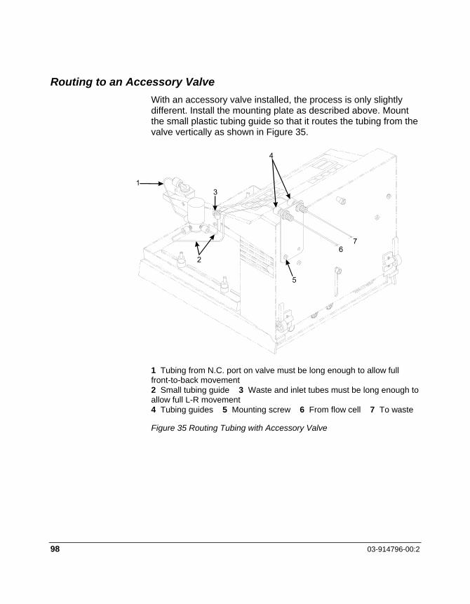
98 03-914796-00:2
Routing to an Accessory Valve With an accessory valve installed, the process is only slightly different. Install the mounting plate as described above. Mount the small plastic tubing guide so that it routes the tubing from the valve vertically as shown in Figure 35.
1 Tubing from N.C. port on valve must be long enough to allow full front-to-back movement 2 Small tubing guide 3 Waste and inlet tubes must be long enough to allow full L-R movement 4 Tubing guides 5 Mounting screw 6 From flow cell 7 To waste
Figure 35 Routing Tubing with Accessory Valve

Appendices
ProStar 704 Fraction Collector 99
Large Diameter Tubing To route large diameter tubing to the drop former, peel the protective cover off the adhesive tape on the bottom of the large plastic tubing guide. Attach the guide to the top of the ProStar 704 as shown in Figure 36.
NOTE: The accessory valves are not rated for use with 1/8-inch ID tubing.
1 Make sure tubing is long enough for drop former to move to all tube positions freely 2 Large tubing guide 3 Adhesive-backed tubing guide 4 From detector flow cell
Figure 36 Routing Large Diameter Tubing
Next, remove the mounting screw on the arm indicated in Figure 36 and use the screw to secure the larger plastic tubing guide to the arm in the position indicated in Figure 36. Route the tubing through the guides and attach it to the drop former.

100 03-914796-00:2
Connection to an Absorbance Detector The information transmitted between ProStar 704 and the detector consists of tube change event marks, inject cycle start, tube advance signal, and analog detector signal. The tube event mark appears as a short negative blip on the chart recorder trace. No separate pen is necessary to generate these marks.
ProStar 704 has an internal peak separator, so the analog peak signal from the detector may be used directly. The peak separator locates peaks by change of slope in the detector signal. As the beginning and end of each peak, the peak separator causes ProStar 704 to change tubes; therefore, each peak is put into its own tube with no dilution from preceding or succeeding baseline effluent. ProStar 704 may also use the peak separator in the detector. Be sure that only one instrument’s peak separator is functioning; the other’s must be turned off.
ProStar 704 may be connected to various detectors or recorders via the rear panel Detector connector using an optional interface cable. Table 5 lists the function, wire color, and pin number of the Detector connector input/output signals available with the optional interface cable (P/N R000088486).
The most basic signal exchanges between ProStar 704 and the detector are the tube advance/event mark signals. The ProStar 704 tube advance requires a TTL level logic 0 (or contact closure) to initiate a tube change. The minimum pulse width is 50 milliseconds and the maximum allowable voltage is +5 Volts. Whenever ProStar 704 advances, the Event output is active: this is an open collector output signal on pin 7 (blue wire) relative to the circuit common (white wire) on pin 8. This input is capable of switching up to +12 VDC at 100 mA DC. The use of this signal for non-Varian instruments varies depending on the capabilities of the detector or recorder.

Appendices
ProStar 704 Fraction Collector 101
Connection to Other Pumps ProStar 704 may be connected to various pumps using the rear panel Pump connector. Table 4 lists the function, wire color, and pin number of the Pump connector signals available with the cable.
Two signals are used to interface with the pump. The first is the 2e3volumetric count input on pin 1 (orange wire). The count input requires a TTL level logic 0 (or contact closure). The minimum pulse width of the signal is 50 milliseconds. No more than the maximum of +5 VDC should be applied to this input. The ProStar 704 program needs to be set to External Counts collection mode.
The pump pause output on pin 2 (yellow wire), which can switch a load of +12 VDC at 100 mA DC, is used to stop the pump at the end of a run and optionally between tubes.
ProStar 704 Input/Output Connectors The ProStar 704 has 4 connectors, 14 VAC, DETECTOR, PUMP, & SERIAL, at the bottom of the rear panel. Table 4, Table 5, and Table 6 provide detailed, pin-by-pin information on each connector.

102 03-914796-00:2
Table 3 ProStar 704 Rear Panel Connectors
Connector Description Purpose
14 VAC 3-pin locking socket Input for supplied power adapter only.
Detector 8-pin circular DIN socket Interface connection to a detector for automatic peak separation and event marking.
Pump 6-pin circular DIN socket Provides stop signal to pump at the start of the 0.8 second delay between tubes and at the end of the run in both Time and Drops collection modes, or under manual control.
Serial RS-232-C Serial interface to computer.
Table 4 ProStar 704 Pump Connector Pin-outs
Pump Pin Color Type Description
1 Orange Input Count: Pump volumes signal*
2 Yellow Output Pump pause: stops pump between tubes and/or at end of run**
3 Brown Not Used —
4 Red Common Circuit common
5 Black Not Used —
6 Green Reserved Valve controller: Do not connect
K Bare Shield Earth ground
* Inputs are TTL levels or contact closures, active low, 50 ms minimum, +5 VDC maximum. **Outputs are open collector, active low, +12 VDC maximum, 100 mA maximum.

Appendices
ProStar 704 Fraction Collector 103
Table 5 ProStar 704 Detector Connector Pin-outs
Detector Pin Color Type Description
1 Yellow Common Analog common (for use with pin 6)
2 Red Not Used —
3 Green Not Used —
4 Black Input Inject: starts and inject cycle*
5 Brown Input Advance: moves to next tube*
6 Orange Input Analog detector signal: 0-10 mV 0-100 mV or 0-1 Volt (-1.2 to +1.2 useable, -5 to +5 maximum)
7 Blue Output Event: sends a 200 ms pulse when tube is changed**
8 White Common Circuit common
K Bare Shield Earth ground
* Inputs are TTL levels or contact closures, active low, 50 ms minimum, +5 VDC maximum. **Outputs are open collector, active low, +12 VDC maximum, 100 mA maximum.

104 03-914796-00:2
Table 6 ProStar 704 Serial Connector Pin-outs
Serial (RS-232-C) Pin Type Description 1 Shield Earth ground 2 Input RXD RS-232 Serial data in 3 Output TXD RS-232 Serial data out 4 — CTS Connected to pin 21 5 — RTS Connected to pin 25 6 Output DCD Connected to positive RS-232 supply 7 — Circuit common 8 Output DSR Connected to positive RS-232 supply 9 Output PTV Positive RS-232 Test Voltage 10 Output NTV Negative RS-232 Test Voltage 11 Output +5 VREF Internal reference voltage test
point 12 — Analog common (for use with pin 11) 14 Input RS-232 Serial data chain in 16 Output RS-232 Serial data chain out
20 Input DTR Connected to positive RS-232 supply
21 — CTS chain. Connected to pin 4
24 Output +5 VDC supply
25 — RTS chain. Connected to pin 5
13 — No connection
15, 17 18, 19
22, 23
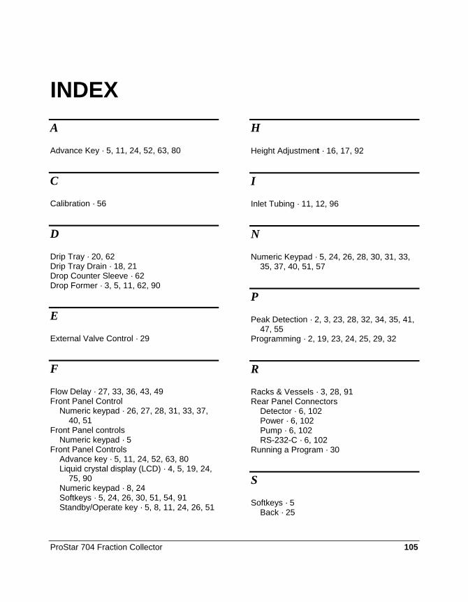
ProStar 704 Fraction Collector 105
INDEX A
Advance Key · 5, 11, 24, 52, 63, 80
C
Calibration · 56
D
Drip Tray · 20, 62 Drip Tray Drain · 18, 21 Drop Counter Sleeve · 62 Drop Former · 3, 5, 11, 62, 90
E
External Valve Control · 29
F
Flow Delay · 27, 33, 36, 43, 49 Front Panel Control
Numeric keypad · 26, 27, 28, 31, 33, 37, 40, 51
Front Panel controls Numeric keypad · 5
Front Panel Controls Advance key · 5, 11, 24, 52, 63, 80 Liquid crystal display (LCD) · 4, 5, 19, 24,
75, 90 Numeric keypad · 8, 24 Softkeys · 5, 24, 26, 30, 51, 54, 91 Standby/Operate key · 5, 8, 11, 24, 26, 51
H
Height Adjustment · 16, 17, 92
I
Inlet Tubing · 11, 12, 96
N
Numeric Keypad · 5, 24, 26, 28, 30, 31, 33, 35, 37, 40, 51, 57
P
Peak Detection · 2, 3, 23, 28, 32, 34, 35, 41, 47, 55
Programming · 2, 19, 23, 24, 25, 29, 32
R
Racks & Vessels · 3, 28, 91 Rear Panel Connectors
Detector · 6, 102 Power · 6, 102 Pump · 6, 102 RS-232-C · 6, 102
Running a Program · 30
S
Softkeys · 5 Back · 25

106 03-914796-00:2
Cal · 56 Clear · 32, 57 Config · 56 Drain · 28, 30, 50, 54 Edit · 8, 26, 33, 35, 37, 40, 54, 58 End · 10, 25, 30, 31, 53, 55 Enter · 8, 90 Info · 57 Next · 31 Park · 32 Peak · 55 RT · 55 Run · 10, 30, 34, 39, 43, 54
Select · 9, 26, 27, 29, 32, 33, 35, 37, 39, 40, 42, 56
Setup · 55 Stop · 30, 50, 54 Test · 57 View · 30, 55 Wdw · 30, 55
Standby/ Operate key · 24 Standby/Operate key · 5, 8, 11, 26, 51
T
Time Windows · 28, 34, 35, 40, 41, 43, 46