big building whitepaper - consoft · big building whitepaper. 2 table of content 1 preface
TRANSCRIPT

1
Big Building Whitepaper

2
Table of Content
1 Preface ...............................................................................................................................42 Challenges .........................................................................................................................43 Definition of Big Buildings ...............................................................................................4
3.1 3D Polygon Count ...................................................................................................43.2 The Project File size................................................................................................53.3 Layout Book Size ....................................................................................................63.4 Team Size ................................................................................................................63.5 No. of stories ...........................................................................................................63.6 Summary..................................................................................................................7
4 Hardware and Software Requirements..........................................................................74.1 Suggested configuration ........................................................................................8
4.1.1 Archicad NetworkKey Servers...........................................................................84.1.2 File Servers..........................................................................................................84.1.3 Archicad Workstations .......................................................................................84.1.4 Rendering and Visualization Workstations......................................................8
4.2 Memory Requirements ...........................................................................................94.2.1 Windows XP Professional..................................................................................94.2.2 Windows XP Professional x64 Edition ..............................................................94.2.3 Mac OS X..............................................................................................................9
5 Speed Issues ...................................................................................................................105.1 3D Rebuild and Navigation ..................................................................................10
5.1.1 The Polycount add-on ......................................................................................105.1.2 How to reduce the 3D model size? ................................................................115.1.3 Sections and Elevations ...................................................................................13
5.2 Rendering...............................................................................................................135.3 Floor Plan Regeneration.......................................................................................14
6 Setting up the Project Team .........................................................................................146.1 Mid-size Office ....................................................................................................... 156.2 Large Office............................................................................................................ 15
7 The Modeling and Documentation Workflow ..............................................................167.1 Small Projects – Single File Concept.................................................................. 177.2 Medium Size Projects –Model File and Document File Separated .................187.3 Big Projects –Hierarchal File Structure..............................................................18
8 Sharing the Project......................................................................................................... 208.1 1. Teamwork.......................................................................................................... 208.2 2. Hotlinked Modules............................................................................................218.3 3. Xrefs...................................................................................................................228.4 4. Documentation Separated from the Model File ........................................... 23
8.4.1 Master file Method ............................................................................................248.4.2 Complex and Distributed methos................................................................... 24
9 Company Standards....................................................................................................... 259.1 The Company Template File................................................................................259.2 Library Management.............................................................................................259.3 Archiving and Data Safety...................................................................................26
10 Case Studies .............................................................................................................. 2610.1 Campus Buildings / Orcutt Winslow Partnership.............................................. 26
10.1.1 About the Company .....................................................................................2610.1.2 Project Details...............................................................................................2710.1.3 Use of PlotMaker...........................................................................................27

3
10.1.4 Use of TeamWork .........................................................................................2810.1.5 Use of Hotlinked Modules ............................................................................ 2810.1.6 Use of Templates..........................................................................................2910.1.7 Use of Details ................................................................................................2910.1.8 Use of Libraries .............................................................................................29
10.2 Offices and Retail Units /John Robertson Architects........................................ 2910.2.1 About the Company .....................................................................................2910.2.2 Project Details...............................................................................................2910.2.3 The Project Workflow ...................................................................................3010.2.4 For Planning:................................................................................................. 3010.2.5 For Tender:.................................................................................................... 30

4
1 Preface
The size and complexity of projects and other important factors like short deadlines or big project teams can significantly influence the design and documentation workflow in an architectural office. To find the most effective Archicad approach foryour practice requires lot of experimenting and refining of your working methods.
The main goal of this white paper is to provide strategy for using Archicad effectively on big projects. You may also find case studies in this document that illustrate how Archicad can be implemented successfully in large firms.
Furthermore it is important to call your attention that the integrated layouting features of Archicad 10 require the complete revision of the documentation workfloweven in those firms where Archicad has been used successfully for a long time. We hope that experienced Archicad users will also find useful information in this book.
2 ChallengesWhat are the possible problems that you have to face when designing big buildings?
• The project team size• Communication with other team members (teamwork)• Communication with partners (DWG-DXF)• Office organization• Document management• File size• Size of the 3D model (Polygon count)• Hardware requirement
3 Definition of Big BuildingsThere is no exact definition for which building is „big” however we can say that the following project attributes have to be carefully examined so that you can find the best Archicad approach:
• 3D Polygon count• File size • Layout book size • Team size • No. of stories
3.1 3D Polygon CountToo many 3D polygons in the Archicad model can significantly slow down theregeneration of 3D, section and elevation windows that in worse case can freezeArchicad. The 3D polygon limitation of Archicad depends on many factors including the computer’s memory, the graphic card’s memory and the type of the active 3D

5
window (internal engine, OpenGL, rendering, section/elevation etc.). For the detailed description of Archicad’s memory requirements please read chapter 4.2.Generally speaking we can say that more that 200.000 polygons results a big model in 3D views and in this case you have to make sure that your computer’s hardware configuration is suitable for the project. Projects with more then 2 million polygons can be unacceptably slow in 3D and may cause Archicad to freeze.Please note that large polygon count or huge file size not necessary means big buildings. In most of the projects significant part of 3D polygons are generated from library parts. The model of a room interior can easily contain as many polygons as a multistory building if the room is furnished with very detailed GDL objects. Please read chapter 5.1.2 for advice how to limit the polygon count.
3.2 The Project File sizeIf the project file exceeds a certain size the input-output operations (e.g. save, save as etc.) can be significantly slower. Furthermore the send and receive times in Teamwork will also increase. Again we can say that there is no explicit number to describe big files. The type and number of Archicad elements placed in the model, the number of layouts or the attributes defined in the project can largely influence the file size. According to the feedback that we received from large clients the maximum file size that Archicad 9 and earlier versions could handle easily was about 100-150 MB. If the project file exceeded this size these companies usually divided them into smaller logical parts to avoid any performance drawbacks. They also found that files bigger then 250-300 MB were slow to redraw in 2D and 3D views and in case of TeamWork files the send and receive time increased significantly.
The handling of large projects has changed positively in Archicad 10 due to the following new program features:
1. File compression: Archicad 10 can save the plan files in compressed format thus less hard disk space is required for project file storage.
2. Intagrated layouting: The layouting functions of PlotMaker are now available in Archicad 10 with fully compatible user interface and interaction standards. With the integration we eliminated the need for a Background ArchiCAD to manage the update process of placed views on layouts. As a result the update time of views are shortened significantly especially with big projects. Furthermore the workflow of editing placed views on layouts is now much smoother. According to our tests Archicad 10 is able to handle even very big projects that contain the 3D model and the complete documentationin one file. In one of our tests we merged the content of a big PlotMaker 9 file (about 150MB) and a large ArchiCAD 9 project file (about 120 MB) in Archicad 10. We found that the size of the resulting AC10 plan file dropped to 70 MB due to the file compression and the merging of the identical project attributes. More importantly Archicad 10 was able to work smoothly with the project in plan, 3D and layout views.
3. Scalable project setup –handling multiple project files: The new user interface provides a transparent overview of hierarchal file structure with multiple model and document files. You can see the structure of all currently running Archicad files of all sessions in the Navigator. This makes it easier to build up the Layout Book and navigate through different files. Layouts can be more easily linked to view data from several source model files.

6
No matter which Archicad version you are using it is very important to control the size of the project files. See chapter 5.1.3 and 7.3 for advice how to curb file size. The following project elements can extend the file size with tens of megabytes so it’s highly recommended to purge the unused ones from the project:
• Sections and elevations• High resolution pictures placed on the floor plan and layouts• Attributes (materials, fills, line types etc.). Note that the unused attributes
can be easily deleted with the Attribute manager• Merged DXF/DWG drawings including many lines, fills and polygons
3.3 Layout Book SizeSeveral layouts in one Archicad project can heavily expand the file size and in case of too many auto rebuild drawings the update process for the entire layout book can be unacceptably slow. You also have to consider that managing 100 drawings from one file could be more complicated then if the drawings were divided into multiple PLNfiles. Our users experience show that in case of more then 50 -100 layouts its worth to separate the documentation from the model file. This way thedocumentation team can work independently from the design team. If the number of layouts exceeds 100 we suggest subdividing the documentation into two or more files.For more information about the new documentation concept of Archicad 10 pleasestudy carefully the corresponding chapters of the Archicad 10 Reference Guide and the Migration Guide.
3.4 Team SizeSharing and coordinating the tasks between the project team members is one of the most challenging jobs of the project leader regardless of which CAD software is usedin the firm. Graphisoft’s TeamWork technology offers an effective solution for this problem even though TeamWork has its limitations mainly because of the send and receives times. If this process takes let’s say 5 minutes for one team member, it can be easily calculated that in case of 10 team members sending and receiving changes for the entire team would take almost an hour. In addition to that the project leader has to regularly check and approve the changes made in the TeamWork file, which prevents the other team members to sign in during the project is being checked. Thus there seems to be a consensus among our TeamWork users that a maximum of 5-6 users can work effectively on one TeamWork file. If you have bigger team we recommend you to apply other working methods, like the hotlink-TeamWorkcombination suggested at chapter 7.3
3.5 No. of storiesDesigning high rise buildings in Archicad sets the following problems:
• many drawings needs to be created and maintained in the layoutbook• typical stories should be generated automatically from the master floor• due to the complex nature of these buildings usually there are many polygons
generated in the 3D model

7
Considering these points we can say that projects with more then 20 storiesrequires special attention from the project leader and the CAD manager. In case of more the 50 stories you very likely have to divide the project by different stories (e.g. basement levels, entrance level, typical floors etc.) and make a separate model file of the whole building for visualization purpose containing only the most important visible elements.
3.6 Summary
The following spreadsheet gives you a short summary of this chapter.
Size is big Size is critical Solutions3D Polygon Count
200.000-1M 2-3 M 1. Reduce the polygon count. See chapter 5.1.22. Split the project file into smaller parts
Project File Size 100-150 MB 250-300 MB 1. Divide the project into smaller parts2. Separate the documentation from the model file
Layout Book Size 50-100 layouts
200 > 1. Separate the documentation from the model file2. Subdivide the documentation into more files
Team Size 4-5 8-10 1. Split the project into smaller parts2. Combine the TeamWork file with hotlink modules
No. of stories 20-40 100> 1. Make a separate modelof the whole building for visualization containing only the necessary elements2. 1. Split the project into smaller parts (e.g. basement levels, typical floors etc.)
4 Hardware and Software Requirements
Before Archicad is implemented in the office the existing infrastructure such as hardware, software, and network solutions, should all be evaluated by the CAD manager. This process is even more critical if the company works with large projectson a regular basis.
8
4.1 Suggested configuration
4.1.1 Archicad NetworkKey ServersIn case the office is using Archicad network licenses a WIBU key server machine has to be installed. This server has to fulfill relatively low hardware requirements:
• The server should support the minimum HW requirements of the operating system
• There should be a free USB port available for the network dongle• The server should be accessible from the Archicad terminals through a
network connection for 24 hours a day• The WIBU technology support cross platform networks thus a Windows key
server can support MAC and Windows Archicad versions simultaneously• The WIBU driver should be installed as a service, so network users can see it
even if no one is logged into the server
4.1.2 File ServersFile servers are primarily used to store Teamwork files, company libraries, templatesor any other materials that are required for the daily operation of the company. File server requirements:
• High storage capacity• Preferably redundant file storage (RAID)• Fast data access• Fast network connection to terminals• High stability and continuous operation 24/7• Graphisoft do not recommend using cross platform file servers in order to
avoid any compatibility problems (e.g. Windows servers for Mac terminals or Linux servers for Windows terminals)
4.1.3 Archicad WorkstationsMost of the project architect will need the following computer configuration:
• RAM: 1-4 GB (depending on the project size) For more details please read chapter 4.2
• HD: Min. 10 GB of free space on the system volume• CPU: Min. PIV 3 GHz or equivalent• Display: 1280x1024 pixels or higher• Graphic Card: Standard OpenGL card with 128MB or more onboard video
memory. For compatibility info, please visit: Archicad-talk.graphisoft.com/Compatibility.php
• Archicad 10 supports the following operating systems: Windows XP Pro Windows XP Pro x64 edition Macintosh® OS X 10.3 Macintosh® OS X 10.4
4.1.4 Rendering and Visualization WorkstationsRendering and visualization requires the most powerful computers. Luckily only a few of these special configurations are needed in a typical architectural office.Requirements:
9
• RAM: 2-4GB (depending on the project size) For more details please read chapter 4.2
• HD: Min. 10 GB of free space on the system volume• CPU: Fast dual processors are highly recommended since most of the
rendering engines (including Lightworks) and imaging applications supports them
• Display: 19” monitor or bigger (1280x1024 minimum screen resolution)• Graphic Card: Standard OpenGL card with 128MB or more onboard video
memory. For compatibility info, please visit: Archicad-talk.graphisoft.com/Compatibility.php
4.2 Memory Requirements
If a requested operation consumes considerable amount of memory in Archicad, the application’s responsiveness can drop significantly, thus making impossible to work effectively with the project. Furthermore if Archicad hits the limit of the available memory address space, the application and/or the operating system will most likely freeze or crash. To minimize the chance of these problems we highly recommend you to buy the maximum memory that Archicad can handle in case you need to work with large projects (See below). The maximum memory that Archicad can utilizedepends on the Operating System and the available memory slots on the computer’s motherboard.
4.2.1 Windows XP ProfessionalWindows XP is 32 bit operating system that supports a maximum of 4GB RAM. Out of the 4GB, the OS allows only 2GB to be assigned to one application. Consequently Archicad can’t address more then 2GB of memory.
4.2.2 Windows XP Professional x64 EditionThe 64 bit Windows OS supports up to 128 gigabytes (GB) of RAM and 16 terabytes of virtual memory. In this case the computer’s motherboard primarily determines the maximum physical memory. AC10 and AC9 (Build 2172 and above) can address a maximum of 4GB out of the total memory
4.2.3 Mac OS XThe latest MAC OS is also a 64 bit system therefore the similar memory limitations apply as for windows XP x64. A maximum of 4GB memory can be addressed from Archicad.

10
5 Speed Issues
5.1 3D Rebuild and NavigationThe most critical speed problems can occur when opening three dimensional views -including sections and elevations- since these operations require the largest amount of physical memory. There are two risk factors to be considered:
1. not enough physical memory available to complete the 3D operation2. the OpenGL card doesn’t have enough RAM for 3D navigation
Both hardware requirements depend mainly on the 3D polygon count of the Archicadmodel. One can easily draw a building on the floor plan and in the section windows which cannot be visualized in 3D due to the excessive number of polygons. The memory consumption at rendering depends on more factors, and the number of polygons is only one of them: problems can occur at lower polygon counts as well(ca. 200.000 polygons) depending on the texture and image quality. If the polygon count increases the next symptom will be the slow conversion to 3D and the unbearably slow navigation in 3D window especially when the entire model is visible.If the model contains approximately 3-4 million polygons the three dimensional navigation is impossible and the render projection outputs a blank image. In case the model contains more than 4 million polygons, chances are high that the application crashes thus preventing Archicad from generating a 3D view of the entire model. These limits of course highly depend on the hardware configuration and other specific circumstances so they cannot be determined exactly. The conclusion is that in case of big buildings it’s essential to keep the model’s polygon count in an acceptable range. The following chapters will give you useful tips for how you can reduce the number of polygons within your projects.
5.1.1 The Polycount add-onPolycount is an Archicad 10 goody add-on that helps to control the number of 3D polygons in Archicad models. This tool can be used effectively if the project size or the limited physical memory of your computer makes the 3D model size a critical factor in your modeling decisions. Polycount can display the number of 3D polygons grouped by element types (walls, slabs doors, windows, objects etc.) and also their percentage compared to the complete model size. The add-on also allows you to change the 3D detail level of certain library parts in your projects. Most objects in the Archicad library includes a “3D Detail Level”parameter with options for “Detailed”, “Simple” and “Off “representations. The “Set Level of Detail” function allows you to toggle between these values. The Polycount add-on can be downloaded from the Graphisoft Archicad 10 Goodieswebsite or by clicking on the “Goodies” link in the Archicad 10 “Help” menu. After the successful installation the Polycount menu can be activated from Window/Palettes/Polycount.

11
The interface of the Polycount add-on
5.1.2 How to reduce the 3D model size?The following tips and tricks can help you to keep the model size in a controllable range:
1. Make layer combinations! They allow you to show only those elements of the virtual building model that are actually needed in the active 3D window. For example there can be one layer combination dedicated for external views such as renderings or elevations, which turn of all the elements that are located in the building’s interior thus can’t be seen. Other layer combos can

12
be defined for internal renderings or sections where the external, trees vehicles or other environmental elements are all hidden.
2. Use the marquee! Once you need to create a section, elevation or rendering of only a small part of the building (e.g. a room or a story) select it with a marquee. This simple trick can speed up the navigation in 3D views
3. Turn OFF the 3D of unwanted objects! As a direct result of virtual building modeling each library part that you place on the floor plan (apart from 2D symbols) has a representation in three dimensional views even if you only intend to show them on the floor plan. Moreover many of these elementsgenerates considerable amount of polygons in 3D. You can overcome this problem if you turn off their 3D representation with the corresponding parameter on the object’s parameter list. Since all library parts in the Archicad library are having the same parameter name for this function you can select multiple objects on the floor plan and turn of their 3D at once. You can also use the “Set LOD” function of Polycount add-on for this purpose.
4. Control the objects’ level of detail! Most library parts in the Archicadlibrary have parameter for 3D detail level (simple, detailed, off) and curve resolution. Set these parameters to the possible minimum that is appropriate for the required 3D view.
5. Avoid using memory excessive library part options! Some optional elements of Archicad object’s can generate significant amount of 3D polygonswithout producing noticeable differences on the final drawings. Please be careful using the following parameters:
• Handles for doors and windows• Taps for bath tubs and lavatories• Curved railings on stairs (including StairMaker stairs)• Too many leaves for plant objects
6. Check the model with Polycount! This handy tool can identify elements ofthe model with too many 3D polygons. In addition to the previously mentioned library parts other problematic elements can be:
• MaxonForm objects• Complex Mesh models (e.g. site model)• 3D people, plants and vehicle objects. Particularly elements imported
from 3Ds, which are usually very detailed models, intended to use in high end renderings instead of architectural visualizations.
The following table shows the polygon count of some Archicad library parts with different parameter settings for your consideration. Note that one detailed office chair object (Man Hands in Pocket) generates as many polygons as 1066 walls! Let’s see one more example that underlines the importance of polygon reduction. One office chair (Office Chair 01) with the default settings makes 3759 polygons in 3D view that is the equivalent of 626 walls. Moreover there are typically many instances of this object are placed in an office project.
Element Type 3D Polygon CountWall without opening 6Wall with empty opening 10D1 Door 80D1 Door with handle (Style 1) 1544Basin 01 (Detailed) 1031Basin 01 (Simple) 685Basin with tap (Detailed) 1335

13
Basin with tap (Simple) 869Man Hands in Pocket 6396People Bitmap 1 1Office Chair 01 (Simple) 2594Office Chair 01 (Detailed, Resolution=8) 3759Office Chair 01 (Detailed, Resolution=16) 7433Car 01 5583Vehicle Bitmap 1Straight StairMaker stair with “Post with Baluster” railing
2093
Straight StairMaker stair with “Simple Surface” railing
789
5.1.3 Sections and Elevations
Other problematic area of 3D views is section/elevation and detail database handling. If a project file has considerable amount of sections/elevations or details, then error messages might occasionally appear during open, save and rebuild processes: „Not enough memory in heap zone” „Cannot read temporary section file”, etc. with the consequence of data loss in the affected project parts. The limit again cannot be determined exactly, because it also depends on the model complexity. Asrule of thumb we can say that the number of the section/elevation and detail windows should never exceed 200. The other consequence of having excessive amount of these views is the file size bloat. Project files with extremely complex 3D models have usually a reasonably small file size (20-30 Mbytes) if the number of sections and details is limited, while a similarly complex project file can be bigger than hundred Mbytes, for instance if there are more than hundred section and detail views. Large files also have negative affect on the Section-elevation rebuild time. Prior to section-elevation generation Archicad runs a pre-filtering on the floor plan. Consequently an invisible 2D view needs to be created before each section-elevation generation. This process can be significantly slower in case the floor plan is big or contains slow to rebuild library parts.
5.2 RenderingReducing the number of polygons with the previously shown techniques helps in two ways in case of photo rendered views:
1. The generation of the 3D view is quicker2. The calculation of the photo rendered image is also faster since the rendering
engine has to work with fewer surfaces
The major difference between a shaded view (e.g. OpenGl) and a photorendering window is that the latter one calculates cast shadows and light reflections. Any method that reduces the number of shadow casting or light reflecting surfaces will result faster renderings. The following techniques can be used:
• Turn off the shadow casting for those library parts that don’t generate noticeable shadows in the actual view. There is a dedicated parameter for this purpose in every Archicad library part.

14
• Use texture mapping and the alpha channel effect instead of physical models.This trick can save precious rendering time in case of trees, vehicles, fences and other complex objects are needed in the photo render image.
• Reduce the number of light sources to the possible minimum. Too many lights sources can result significantly slower renderings.
• Turn off shadow casting for brightener lights.
5.3 Floor Plan RegenerationDrawing on floor plan also has its restrictions, but these are much harder to reach then in case of 3D views. While Archicad is capable of manipulating 500.000 visible elements on the floor plan, a more realistic number would be 100.000 in case of an average construction plan. Although Archicad will not crash or write enormous fileswith more then 100.000 elements, but the responsiveness will be unacceptably sloweven on cutting-edge hardware configurations. Note that more time will be taken to redraw the drawing if you zoom out from a smaller part of the project to the drawing extents. Also remember that the floor plan rebuild time influences the speed of the section-elevation regeneration as described in chapter 7.3.Please consider the following devices:
1. Use layer combinations to control the content of the floor plan!2. Use bitmap fill representations instead of vectorial fills! Unless you need to
print a drawing select the bitmap fill representations from the on screen view options dialog as it is regenerated faster then vectorial fills.
3. Avoid using symbol fills! Symbol fills can largely increase the floor plan redraw time especially if the fill pattern contains many line and arc segments.
4. Only use PROJECT2 commands in library parts if it’s really necessary. Those require the 3D view of the object to be generated for the 2D symbol thus making the floor plan redraw unreasonably slow. Note that MaxonForm objects also use this GDL command. In the MaxonForm manual you can find a description for how you can simplify the 2D of these elements.
5. Use a Symbolic 2D representation for static library parts without scripting the floor plan symbol!
6 Setting up the Project TeamSuccessful implementation of Archicad requires well documented office standards, trained office staff and proper organization of the project teams. This topic has been discussed in more details in the “Introduction to Office Standards” and in the “Creating Large Building Models” documents.
Here we only want to give you a few points to consider for the project team set up:• How many projects run parallel in the office?• How many architects can work simultaneously on one project?• How are the projects being shared (by Teamwork, hotlinked modules,
layouting in separate files etc.)?• Should you hire a full time CAD manager and/or IT manager?• Will you need independent design and visualization teams in the firm?
Naturally there are no generally applicable answers for these questions. Moreoverthe organizational hierarchy within the office can dynamically change during the lifecycle of a project thus there is no use to set up any strict rules. Based upon our users’ feedback we suggest the following:

15
• Get a full time CAD manager if more then 15-20 architects are working in the office
• Even in case of 5-15 architects it is recommended to appoint a part time CAD manager from the project team
• The CAD manager (in collaboration with the IT manager and the office principals) should be responsible for developing the office standard book
• As previously mentioned a maximum of 5-6 users can work effectively on one TeamWork file, consequently this should be an important factor when setting up the project teams
6.1 Mid-size OfficeThe following charts show the organizational hierarchy of a typical mid-size and a large office. In this example, there are two independent project teams with 2 architects and 2 draftsmen working in each. The leader of the first team also serves as a part time CAD manager in the office. Due to the relatively small firm size and the generally limited-size projects, informal communication is sufficient to handle project coordination issues in most cases. The typical problem for offices of this size is that they can’t afford a full-time CAD and IT manager, so somebody in the office has to tackle these problems part-time, which naturally decreases that person’s productivity.
Mid-size architectural office (10-15 employees)
6.2 Large OfficeThe large architectural office shown on the next figure is subdivided into 4 teams. The first two are working on a large project therefore their tasks are coordinated by a project director. The project director and the leaders of the other two project
Principal(s)
Project Leader 2 Office Administration
Project Architect 1Project Architect 2
Draftsman 1Draftsman 2
Project Architect 1Project Architect 2
Draftsman 1Draftsman 2
Project 1 Project 2

16
teams are reporting to the Design Director. In this example a full time IT and CAD manager assist the project teams. The biggest challenge for these firms is to automate the sharing of large projects and to ensure the adoption of office standards within the whole office team.
Large architectural office (30-50 employees)
7 The Modeling and Documentation Workflow
Principal(s)
Design Director
IT Manager
CAD Manager
Office Administr
ation
Project Director
Project Leader
Project Leader
Design Team
Project Leader
Project Leader
Project Architects Draftsme
Project Architects Draftsme
Project Architects Draftsmen
Visualization Team

17
The single file concept of Archicad has proven itself well in small firms with small to medium sized projects. More extensive organizations with larger projects have to divide them into several files for many practical reasons. Those reasons include performance drawbacks of single file method and workflow bottlenecks with multiple users working against one file. Archicad 10 supports different scale projects by providing a transparent method of handling multiple sessions and views to this complete collection of files. Basically there are three typical workflows in Archicad10, which can be combined depending on the actual project:
7.1 Small Projects – Single File Concept
This is the suggested Archicad workflow for small to medium scale projects. The complete 3D model (virtual building data) with its representations (floor plans, sections, 3d views, schedules etc.) and the final drawing sheets (layouts) are included in one Archicad file. This method can fully exploit the advantages of the virtual building concept such as easy file management, automatic drawing updates and listing. However above a certain project size and complexity the Archicad plan file has to be divided into smaller parts to avoid speed and project management problems. Our tests show that projects smaller then 50-100 MB can be handled smoothly in one project file. For more details please read chapter 3.2.
The Archicad single file concept
LAYOUTBOOK
Virtual Building
Database
Floor plans
Sections
Details
3D views
Schedules
Layout
Layout
Layout
Layout
Layout
ARCHICAD PROJECT FILE (PLN)
18
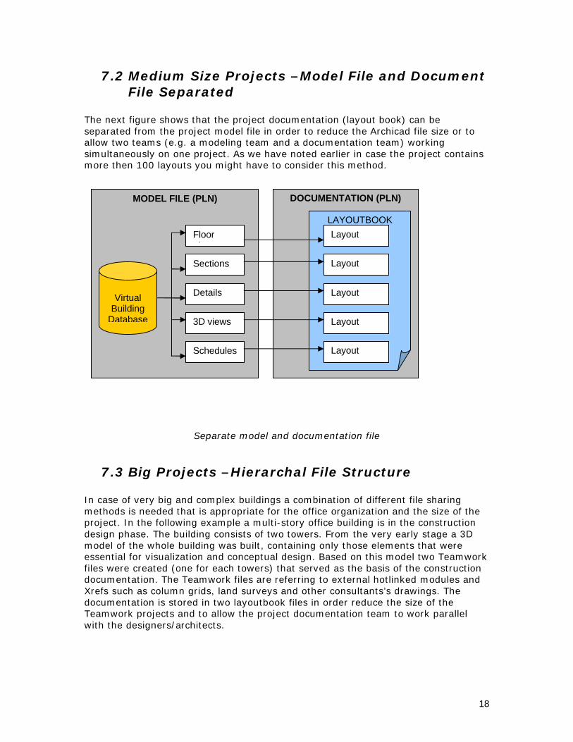
7.2 Medium Size Projects –Model File and Document File Separated
The next figure shows that the project documentation (layout book) can be separated from the project model file in order to reduce the Archicad file size or to allow two teams (e.g. a modeling team and a documentation team) workingsimultaneously on one project. As we have noted earlier in case the project contains more then 100 layouts you might have to consider this method.
Separate model and documentation file
7.3 Big Projects –Hierarchal File Structure
In case of very big and complex buildings a combination of different file sharing methods is needed that is appropriate for the office organization and the size of the project. In the following example a multi-story office building is in the construction design phase. The building consists of two towers. From the very early stage a 3D model of the whole building was built, containing only those elements that wereessential for visualization and conceptual design. Based on this model two Teamwork files were created (one for each towers) that served as the basis of the construction documentation. The Teamwork files are referring to external hotlinked modules and Xrefs such as column grids, land surveys and other consultants’s drawings. The documentation is stored in two layoutbook files in order reduce the size of the Teamwork projects and to allow the project documentation team to work parallel with the designers/architects.
DOCUMENTATION (PLN)MODEL FILE (PLN)
Virtual Building
Database
Floor plans
Sections
Details
3D views
Schedules
LAYOUTBOOK
Layout
Layout
Layout
Layout
Layout

19
Complex file hierarchy
Hotlink
Module
XREF(dwg
TeamWork File 01
(plp)
Layoutbook File
01
Layoutbook File
02
Hotlinks
TeamWork File 02
(plp)
XREF(dwg
3D Model File for
Visualization
Hotlinks
Independent Detail Drawings
(dwg)
Pictures(jpg, tif etc.)
Hotlink
Module
Hotlink
Module
Hotlink
Module
Hotlink
Module
Hotlink
Module

20
8 Sharing the ProjectCollaboration is essential for making the project team function and moving projects forward as rapidly as possible. Effective collaboration and project sharing techniques are able to adapt to the project team size and the office organization. Archicad offersvarious solutions for project sharing that can be used alone or in combination.
8.1 1. TeamworkGraphisoft’s award winning Teamwork technology provides an effective method for sharing Archicad projects. TeamWork allows your office to define different team roles, such as "team leader," "team member," "administrator" and "visitor." Depending on the function assigned to them, team members have specific rights to access and modify the central project file. The basis for collaboration is a central project file shared among team members. Team members can reserve their own workspaces by applying restrictions to particular areas, stories, and/or layers: as a result, each Archicad element will have an owner with the exclusive right to modify it.
The Teamwork conceptAdvantages:
• Team members roles are clearly defined• Team members can continuously check the others work• No conflicts can occur in the architect’s workspace• The Teamwork file is always up to date
Limitations• Send and receive can be slow in case of large models (more then 100 MB)
TeamWork File (PLP)
Local Copy 01
(PLC)
Send & Receive
Local Copy 02
(PLC)
Local Copy 03
(PLC)
Workspace
Workspace
Workspace

21
• Users can’t send and receive changes simultaneously therefore the CAD manager has to set up a schedule for the sending and receiving changes (Typically during lunch time and after the office hours)
• The maximum number of concurrent TeamWork user’s are limited by the send and receive times (Typically 5-6 architect can work effectively on one project)
Suggested UsageTeamwork should be your primary method for sharing the content of the virtual building. In case of very large files and/or more then 5-6 team members we suggest dividing the project into more TeamWork files. Thus you can significantly reduce the send and receive times.
8.2 2. Hotlinked Modules
Using Hotlinked Modules allows you to insert the content of external Archicad files (sources) into the currently open Project (host). Elements inserted into the host follow all modifications of the source files.
Hotlinked Modules can be used, for example, to manage the repetitive structures of buildings such as hotels or offices with a large number of identical rooms by modifying all instances in a single step. Moreover, the same structures can be used in multiple Projects. This is also a good way to subdivide large Projects into easier-to-handle smaller files.
The elements of hotlinked modules are included in the Project, which means that even if the hotlinked source file is not currently available, the Modules are still present and visible, and they just can't be updated as long as the referred source file is absent. However this also means that using hotlink modules doesn’t reduce the size of the master project

22
The Hotlink module concept
Advantages:• Module files can be updated automatically or manually• Updating a module is fast and easy• Repetitive elements of the project can be controlled and modified easily
Limitations• Access to the content of the modules can’t be controlled in Archicad• Nested modules are not updated automatically• No protection against workspace conflicts• A detailed module organization chart has to be created by the project
coordinator before the project is started• Doesn’t reduce the size of the master file
Suggested UsageAlthough hotlink modules can be used as an alternative to the TeamWork technology (e.g. different floors of a multi story building can be drawn in separate hotlink modules) they can’t provide the same flexibility and security that TeamWork can. The main purpose of using TeamWork should be the management of repetitive elements in the projects.
8.3 3. Xrefs
Xrefs provide an easy way to manage and merge the consultants DWG/DXF drawingsinto the Ac project. External DWG/DXF drawings will be automatically updated in the
Project File(PLN, PLA, PLP)
Hotlink Modul
Module File (MOD, PLN)
Nested Module(MOD, PLN)
Hotlink Modul
Hotlink Modul
Hotlink Modul
Hotlink Modul
Hotlink Modul
Module File
(MOD, PLN)Hotlink Modul
Hotlink Modul
Hot
link
Hot
link
Hot
link
NO
23
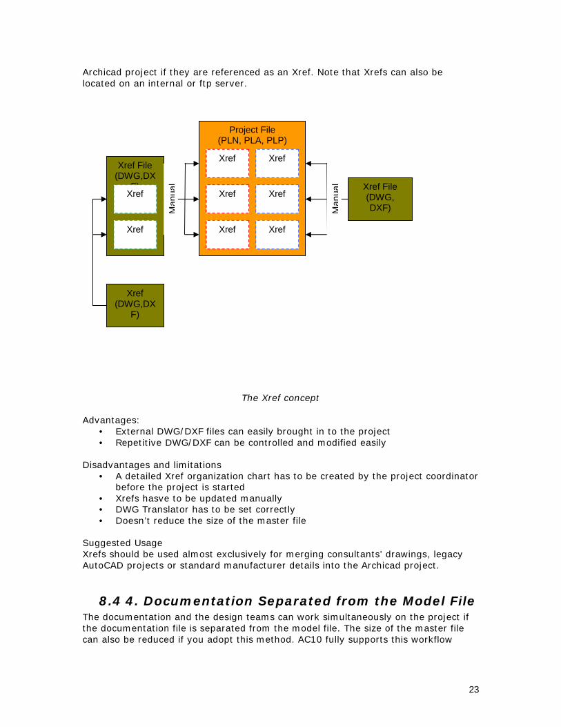
Archicad project if they are referenced as an Xref. Note that Xrefs can also be located on an internal or ftp server.
The Xref concept
Advantages:• External DWG/DXF files can easily brought in to the project• Repetitive DWG/DXF can be controlled and modified easily
Disadvantages and limitations• A detailed Xref organization chart has to be created by the project coordinator
before the project is started• Xrefs hasve to be updated manually• DWG Translator has to be set correctly• Doesn’t reduce the size of the master file
Suggested UsageXrefs should be used almost exclusively for merging consultants’ drawings, legacy AutoCAD projects or standard manufacturer details into the Archicad project.
8.4 4. Documentation Separated from the Model FileThe documentation and the design teams can work simultaneously on the project if the documentation file is separated from the model file. The size of the master file can also be reduced if you adopt this method. AC10 fully supports this workflow
Project File(PLN, PLA, PLP)
Xref
Xref File (DWG, DXF)
Xref(DWG,DX
F)
Xref
Xref
Xref
Xref
Xref
Xref File (DWG,DX
F)Xref
Xref
Man
ual
Man
ual

24
since you can control complex file hierarchies in the new Navigator dialog. There are two strategic ways of separating the documentation from the model.
8.4.1 Master file MethodIn this scenario there is a master Archicad file that contains the complete Archicadmodel, and the corresponding view sets. The documentation file refers to the view sets of the model file and automatically updates the drawings if the model file is changed. This method is applicable for medium to large scale projects.See the corresponding chart at chapter 7.1
8.4.2 Complex and Distributed methosIn case of very complex or large projects usually there is no master file that contains all the drawings due to size and speed problems. Consequently the building model is stored in multiple project files (some of them can be TeamWork files; others can besimple Archicad project files that refers to hotlinked modules). There are two ways to import the drawings into the documentation file
1. Drawings are saved individually as PMK files and linked to the Archicaddocumentation project file. In this case there is no direct link between the model file and the document file, thus the drawings on the layout doesn’t follow the changes of the model file automatically. This method is only recommended if the PMK files are final or rarely updated or if the automatic drawing update from the model file is too slow.
Manual PMK saving and linking to the document file
2. Drawings are imported into the layoutbook directly from one or more building model files and other external file sources (DWG, DXF, PDF-s, image files, PMK-s etc.). In case of very complex building the documentation file can also be subdivided into two or more parts for easier drawing management. See the corresponding chart at chapter 7.3
This is a complex system but very powerful and in some cases may be the only way to handle very large projects. In case of complex documentation structures are used in the office it is crucial that the CAD manager/project leader develops and publish
DOCUMENTATION (PLN)MODEL FILE (PLN)
Virtual Building Databas
LAYOUTBOOK
PMK
PMK
PMK
Manual update

25
the suggested file hierarchy for the project team members prior the CD phase is started.
9 Company Standards
Well documented company standards are essential for running a large office successfully. It is even more crucial in case of large building when typically big project teams are working the same project file. It is primarily the CAD manager’s responsibility to develop and maintain the office CAD standards. Below is just a short description of what should be included in the CAD standard document. For more details please read the Introduction to Office Standards document:
9.1 The Company Template FileThe company template file is the most critical element of the office CAD standard. Whenever a new project is started the project leader must use this template as the basis of the project master file. A comprehensive office template should contain the following elements:
• Attributeso Layerso Layer combinationso Penso Pen Setso Materialso Line Typeso Fill typeso Composites
• Complex Profiles• Schedules• Model view options• View sets • Project preferences• Favorites• Layouts• Layout Master pages
9.2 Library ManagementLibraries are crucial parts of the Archicad projects. In a typical architectural firm fourtypes of libraries are used:
1. Archicad Library is the most current version of the Archicad object library orin some cases just a subset of it. The subset library contains only those elements of the standard Archicad library that are regularly used in the company.
2. Office Standard Library is a collection of those objects that were developed according to the office requirements. This library typically includes annotation elements (e.g. markers, labels, drawing frames etc.) and 3D objects (e.g. doors, windows, curtain walls etc.).
3. Project Specific Libraries consists of those custom elements that were made specifically for the actual project. Most of these objects are made by the project team members.

26
4. A number of Third Party Libraries can be found on the Internet with useful objects that may not be found in the Archicad library.
The above four libraries can reside on the company file server or on the teammembers’ computer.
For best performance we suggest the following library storing strategy:• Archicad Library and Office Standard libraries are installed on every user’s
computer by default. Libraries are stored in container file format (LCF) and users not allowed to modify them. Only the CAD managers have the rights to update them.
• Project Specific libraries are stored on the company file server. The library is not compressed and project team member’s can freely edit its content.
• The location of third party libraries depends on how often they are used. Regularly used objects should be installed on the users’ computer while the others can be stored on the company file server.
9.3 Archiving and Data SafetyIt is also the CAD manager’s responsibility to develop the standards for:
• Proper use of the Archicad archive file (pla)• Location of Autosave and backup files• Backup and Autosave times
10 Case Studies
The following case-studies illustrate that entirely different Archicad workflows can been adopted successfully in many large offices. The key to success is that the selected approach should be adequate for the project type and the office organization.
10.1 Campus Buildings / Orcutt Winslow Partnership
10.1.1 About the CompanyOrcutt Winslow Partnership (http://www.owp.com/) is located in Phoenix Arizona. This prestigious architectural design firm has more then 30 years of history. OWPwas recently designated as one of the best managed architectural firms in the United States by Architectural Record magazine. The company’s main profile is designing campus type buildings (large high schools, hospitals). By the time this document was written the office was entirely using AC9 on MAC computers, thus they had no experiences with AC10.

27
10.1.2 Project DetailsOWP was working on two campus projects at the time of the interview. One was a 51000 sqf school building and the other one was also an educational complex with 4 buildings and a total of 94000 sqf floor area. Campus buildings are typically not more then 4-5 stories high thus the number of floors or the size of one building is not critical. More important is that the final construction documentation has to containthe complete documentation of each building. The complex hierarchy of drawing and the large number of layouts in the in the final layoutbook makes the documentation the most complicated part of the project
10.1.3 Use of PlotMakerIn most of their projects OWP reached the limits of live hotlinks in PlotMaker 9. Therefore they do not work with live hotlinks, but separate PMK files instead. They found that the most critical bottleneck of PM lies in the slow updating of hotlinks with background Archicad. The integrated layouting features of AC10 brought significant changes in this field so OWP is looking forward to test it on its projects.
They usually work out 3 layout books for a typical project. They begin with one that contains sketches, then progress with a new one for schematic design and finallymake a separate one for design development. The design development layout book is then converted into the construction documentation layout book.
Because OWP mostly designs campus type buildings and have many building files, they do not use the auto numbering feature of PlotMaker.

28
10.1.4 Use of TeamWorkThe largest buildings they design is around 4-5 storey ones so this is not a critical factor for them. They work with TeamWork files not more the 100 MB. They found that this is the upper limit that TeamWork can handle smoothly. If they exceed thisfile size then they often take the project apart by stories as separate PLP files.
They share the model by layers and have separate layer sets for interior design team. Most of the time only 1 or 2 architects are responsible for the design and they get help for CD-s and interior designs at the CD stage.
Once they had a large Patient tower hospital building where they had 10 people working together on a single PLP file. This project required a full time CAD manager that worked only as an administrator for the teamwork model.
They are committed to Teamwork; only the interior team prefers using hotlink modules for team working. Now they have a habit of saving plc files and send and receive only once or twice a day. Some of the office even signs in from home over the internet even though it takes around 20 minutes.
10.1.5 Use of Hotlinked ModulesAs OWP typically designs campus type buildings, they often hotlink the different building model files into the site plan file. Interior team use hotlink modules mostlyfor repetitive or standard elements.
The picture below shows the Willie and Coy Payne Junior High School in Gilbert Arizona. The following collaboration and coordination techniques were used during the design:
• Civil (dwg) site information was linked to Archicad site plan via x-referencing• Teamwork was used on individual building files to share each building model• 3D building were linked (hotlinked) to site for consistency• All views of all buildings were linked to layout book for automatic
documentation
29
10.1.6 Use of TemplatesOWP created an extensive template set for their practice. They have dedicatedtemplate files for:
• new building• remodel (for refurbishments)• site plans• tenant improvements• general notes (sheet index, consultant names and all the project admin info is
within this file)
10.1.7 Use of DetailsOWP have standard detail files where the details are kept in detail windows. As they have modified the details for the actual project, they create project specific details.
10.1.8 Use of LibrariesThey were just in the process of changing the office library policy. They want to have the:
• Project libraries on the server• Office library on the server• Archicad library on local machines
10.2 Offices and Retail Units /John Robertson Architects
10.2.1 About the CompanyJohn Robertson Architects (http://www.jra.co.uk/) is a London-based architectural firm with about 45 professionally qualified and support staff. JRA has worked on different types of projects including residential commercial design and urban planning. Many of their recent projects are new or refurbished office buildings in the City of London.
10.2.2 Project DetailsBuilding type: Offices and retail units in the City of London. The scheme strips a 1950’s office back to its frame and extends the building, doubling its size. Area: 26 000 192 m2Cost: GBP 35 700 000Client: Carlyle GroupContractor: ISG Interior Exterior
JRA is the design architect. The project now is in tender stage. It is a 2 stage major works contract. JRA is currently in production of all the tender documents for all packages.

30
10.2.3 The Project Workflow
10.2.4 For Planning:JRA has been the design architect of this project from the start.John Robertson (main partner, not working with Archicad) with a design architect (working with Archicad) worked out the scheme for planning approval. 2 other employees helped in creating the final CAD documents for the planning application. At this stage there was no teamworked model. There was a main 3D model file out of which all the plans, sections, elevations and 3D views were obtained.
10.2.5 For Tender:When they received the go ahead from the client to produce the tender documents, they created what they call a “Base Model”. (see the figure below). The Base Model , which is a teamwork file, contains the main structure of the building (columns, slabs, main external walls, etc…), but no 2D information. Only the most competent Archicad users work on this part of the project (about 2 persons) and access to this is password protected. The main reason for this is to reduce errors to the most important portion of the building, the structure.
The Base Model is then hotlinked into the so-called General Architectural Model (GA). The secondary 3D information (raised floors, false ceilings, partitions, etc…) is added together with all the necessary 2D info for the GA plans, sections and elevations that derive directly from this model. Sections and elevations come directly from this main GA model file, are kept in the
file, but exploded to 2D and moved away from their original place by a certain distance. Then they are elaborated with 2D details.

31
All other 2D information (soft floor finishes, screed layouts etc.) is made by hotlinking out of the GA Model to linked pln files. This keeps teamworking to a minimum and avoids bloating the size of the GA Model through the addition of 2D information whist ensuring that the 2D information remains up to date.
Many other parts of the building (like entrance hall, core details etc…) are kept as separate pln files and are directly hotlinked into the GA Model file.
Final layout creation is done in PlotMaker. This project has a number of layout books that have direct links to views contained in the GA Model file.The main GA model file size is no ~ 50 MB-s. (what do they think on AC10 integrated layouting)
This chart represents the current Archicad working method within JRA: