bhel documents no.: pe-ts-367-174- technical · pdf file · 2013-07-201x700 mw...
TRANSCRIPT

BHEL DOCUMENTS NO.: PE-TS-367-174-14000-A001
VOL- IIB SECTION-D1
1X700 MW BELLARY 3 STPP REV. NO. 00 DATE: 29/05/13
BHEL – PS –PEM- PPEI: NOIDA, SECTOR-16A, U.P. – 201301.
TITLE: TECHNICAL SPECIFICATION FOR
COOLING WATER OZONE GENERATION PLANT
ii) C.I Pipe / Ductile Iron - 100 iii) Rubber lined steel pipe - 120 iv) PVC / HDPE pipes - 140 For calculating the pump head, at least 20% margin shall be taken over the pipe friction losses. 2.01.10 All piping system shall be capable of withstanding the maximum pressure and temperature in the
corresponding line. 2.01.11 Fittings (a) Fittings to be used with carbon steel pipes shall conform to IS:1239 Part-II (Heavy grade)
for sizes up to 150 NB. (b) For sizes 200 NB & above steel fittings shall conform to ASTM A 234 Gr. WPB.
However for sizes above 350 NB fabricated fittings (meter bends etc) may be used. Forged elbows of long radius shall be used.
(c) For Galvanized pipe application all the fittings shall be galvanized as per IS:4736. (e) Fittings to be used in other type of piping shall conform to relevant IS/BS ANSI
Standards and in conformity with the parent pipe standard. (f) Unless otherwise shown eccentric reducers shall be installed with straight side at the top
of piping connection. 2.02.00 Design of Piping Systems 2.02.01 Steel pipe flanges shall be generally slip on flat face type. Weld neck flanges shall be used when
flange follows immediately after a butt-welding or where it is required with respect to service conditions. When weld neck or socket weld flanges are used, their bore must be made the same as that of the pipe being welded to. Socket welded or threaded flanges may be used, with the appropriate piping system for connection of pipe to the flanged equipment.
2.02.02 All the piping flanges and counter flanges & their drilling shall conform to ANSI B 16.5 of relevant
pressure & temperature class. Flanges shall conform to ANSI B.16.5 class 150 (min.). 2.02.03 For easy handling & removal of equipments, valves etc. and for maintenance purpose, break up
flanges for 65 NB and above sizes and suitable type of compression flexible coupling for flanged joints of 50 NB and below size shall be provided. The over ground piping wherever routed inside building, shall have a clear head room of minimum 2.1 meter from operating floor.
2.02.04 Pipes shall generally be routed above ground but where specifically indicated/specified the pipe
may be laid in trenches or buried. Buried piping shall be generally installed so that the top of pipe is 1.0 metre below the ground level unless otherwise specifically mentioned. Full length of buried piping shall be provided with 100 mm thick sand bed.
2.02.05 Butt-welding edge preparation shall be done as per ANSI B 16.25. 2.02.06 Hangers and supports shall be capable of carrying the sum of all concurrently acting loads. They
shall be designed to provide the required supporting effects and allow pipeline movements as necessary. All guides, anchors, braces, dampener, expansion joint and structural steel to be attached to the building/structure, trenches etc. shall be provided. Type of hangers and components for all piping shall be selected and approval obtained from BHEL.
2.02.07 Pipe coming under purview of IBR should meet its requirements and getting the IBR approval
shall be under Vendors scope. 3.00.00 VALVES
Page 188 of 277
BHEL DOCUMENTS NO.: PE-TS-367-174-14000-A001
VOL- IIB SECTION-D1
1X700 MW BELLARY 3 STPP REV. NO. 00 DATE: 29/05/13
BHEL – PS –PEM- PPEI: NOIDA, SECTOR-16A, U.P. – 201301.
TITLE: TECHNICAL SPECIFICATION FOR
COOLING WATER OZONE GENERATION PLANT
3.01.00 Valves will be used to start/stop or control flow. Sample valves will be used in sample collection
lines. 3.02.00 All valves, shall be suitable for service conditions i.e. flow, temperature and pressure under which
they are required. All the valves shall be of standard pressure rating of the relevant design standard. All the actuators of the valves shall be designed to handle the maximum expected pressure differential across the valves and to overcome friction forces and unbalance forces due to the flow through valve.
3.03.00 GATE VALVES Sluice/gate valve shall conform to IS 14846 of rating PN 1.6 (min.). Stem, seat ring and wedge
facing ring shall be of stainless steel construction. Other parts shall be as per IS:780. Flanges shall be designed as per ANSI B 16.5 Cl. 300 (min.) to meet with the piping flanges. Valves shall be of outside screw and rising stem type.
Sluice valves for sizes below 50 NB and below shall conforms to IS:778 Class-2/ANSI B16.34
straight, rising stem; without side screw. 3.03.01 Sluice valves shall be provided with the following accessories in addition to the standard items. a) Hand wheel b) Manual Gear reduction unit operator for valves 250 NB and above. c) Draining arrangement wherever required. d) Arrow indicating flow direction. e) Position indicator. 3.03.02 Sluice Valves shall be provided with back seating bush to facilitate gland renewal during full open
condition. 3.04.00 BUTTERFLY VALVES Butterfly valves shall be of double flanged of low leakage rate confirming to AWWA-C-504 class
150 (min.) or BS:5155 PN 10 (min.) 3.04.01 The various components of butterfly valves shall be of the following i) Body : SS316 ii) Disc. : SS316 iii) Shaft : SS410 iv) Seat rings : Nitrile rubber, EPDM (Ethylene propylene rubber) v) Hand wheel : Cast iron or Malleable iron. 3.04.02 Butterfly valves shall be fitted with sleeve type bearing such as PTFE. Valves of size 350 NB and
above shall be provided with one or two thrust bearings to hold the disc securely in the centre of valve seat without hydraulic or external axial shaft loads. Sleeve and other bearings fitted into the valves body shall be of self lubricated materials that do not have any effect on the fluid handled and other components of the valves.
3.04.03 All the butterfly valves shall be provided with Hand wheel or lever as per the requirements. For larger sizes i.e. 150 NB and above hand wheel shall be provided. For lever/wrench operated
valves, means shall be provided for positively holding the disc in not less than three intermediate
Page 189 of 277

BHEL DOCUMENTS NO.: PE-TS-367-174-14000-A001
VOL- IIB SECTION-D1
1X700 MW BELLARY 3 STPP REV. NO. 00 DATE: 29/05/13
BHEL – PS –PEM- PPEI: NOIDA, SECTOR-16A, U.P. – 201301.
TITLE: TECHNICAL SPECIFICATION FOR
COOLING WATER OZONE GENERATION PLANT
positions. Manually operated valves shall be provided with reduction gear unit for valves of size 250 NB and
above. Valve provided with motorized or pneumatic actuator shall be provided with a hand wheel for manual operation.
All the valves shall be equipped with adjustable mechanical stop-limiting devices to prevent over
travel of the valve disc in the open and closed positions. The valve operators (Hand wheel or Gear reduction unit or Motor actuator etc.) shall be designed as per relevant International Standard.
3.04.04 All the butterfly valves shall be provided with an indicator to show the position of the disc. Flanges
shall conform to ANSI B 16.5 Cl.300 (min.) 3.05.00 BALL VALVES i) Design Standard : BS:5351 Class 150 (min.) ii) Type : Welded/Flanged ends; Full bore:
Split Body & Seat supported construction.
iii) Material of Construction Body : SS316
Ball : SS316
Seat ring : PTFE
Stem : Stainless steel AISI 420
Seats : Nitrile rubber; PTFE. Hand wheel : Cast iron or Malleable iron.
iv) Valves shall be designed to be directly operatable by a wrench / Hand lever. v) Suitable stops shall be provided for both the fully open & close condition. vi) All the valves shall be provided with an indicator for showing the position of the
ball port. 3.06.00 NON-RETURN VALVES (CHECK VALVES) 3.06.01 Non return valves shall be of swing check (reflux) type or dual plate type. 3.06.02 The valves shall conform to the following specifications. i) Design Standard : IS:5312, BS:1868, BS:5153 API 594/
API 600 or Eqvt. ii) Type : Swing check or dual plate type and Flanged ends. iii) Material of Construction a) Body & Cover : SS316 c) Disc facing ring : SS316 d) Body Seat ring : SS316 e) Bearing bushes : Leaded Tin Bronze IS:318 Gr.2 f) Bolts : Carbon Steel
Page 190 of 277
BHEL DOCUMENTS NO.: PE-TS-367-174-14000-A001
VOL- IIB SECTION-D1
1X700 MW BELLARY 3 STPP REV. NO. 00 DATE: 29/05/13
BHEL – PS –PEM- PPEI: NOIDA, SECTOR-16A, U.P. – 201301.
TITLE: TECHNICAL SPECIFICATION FOR
COOLING WATER OZONE GENERATION PLANT
3.06.03 Body shall be permanently marked with an “arrow” inscription indicating the direction of motion of
the fluid for all the check valves. 4.00.00 STRAINERS 4.01.00 Y-Type Strainer a) Y-Type strainer for water application shall be constructed of following materials : i) Body : SS316 ii) Strainers : Wires of stainless steel AISI-316, 18 BWG 30
mesh suitably reinforced. Reinforcement material shall also be of stainless steel construction.
5.00.00 General Requirements for Valves, Gates, Strainers
All the equipments shall be of proven design for the duty conditions and the contractor or manufacturer shall have sufficient experience in using the above equipments in water treatment application in the plants supplied earlier by them.
In case BHEL desires, the experience list/feedback from the users shall be made available to
BHEL for any or all the equipments during the detailed engineering phase.
Valves coming under the purview of IBR if any shall meet its requirements and the approval of the same shall be obtained by the contractor.
Sizes of the valves shall be same as that of the interconnected pipe sizes.
The various equipments shall be installed so that they are easily approachable for the operating
and maintenance personnel. Generally Valves shall be located about 1.2 meter to 1.5 meter from the operating platform and also they shall not be located below the ground level such as beneath the trenches etc. In such cases, extended spindle shall be provided with chain operating from operating floor. Valves which are installed below the ground floor shall be provided with a floor mounted pedestal at the top of the operating floor. The position indicator for such valves shall be also provided along with the stand.
However valves which are provided (in the burried pipe line) with a valves chamber shall have
manual operator/Hand wheel inside the valve chamber. The valve chamber shall be provided with built in ladders/staircases and sufficient operating space within the chamber shall also be provided for easy operation of such valves.
Page 191 of 277

BHEL DOCUMENTS NO.: PE-TS-367-174-14000-A001
VOL- IIB
SECTION-D1
1X700 MW BELLARY 3 STPP REV. NO. 00 DATE: 29/05/13
BHEL – PS –PEM- PPEI: NOIDA, SECTOR-16A, U.P. – 201301.
TITLE: TECHNICAL SPECIFICATION FOR
COOLING WATER OZONE GENERATION PLANT
GENERAL TECHNICAL REQUIREMENT FOR
PRESSURE & STORAGE VESSEL
Page 192 of 277

BHEL DOCUMENTS NO.: PE-TS-367-174-14000-A001
VOL- IIB
SECTION-D1
1X700 MW BELLARY 3 STPP REV. NO. 00 DATE: 29/05/13
BHEL – PS –PEM- PPEI: NOIDA, SECTOR-16A, U.P. – 201301.
TITLE: TECHNICAL SPECIFICATION FOR
COOLING WATER OZONE GENERATION PLANT
1.00.00 GENERAL The following principal pressure and atmospheric vessels for the system has been covered in this
part of specification.
1. Air receiver 2. Oxygen receiver
3. Air driers
4. Oxygen generators
5. Portable water storage tank
1.01.00 Of these, the items specified from Sl No. 1 to 4 shall be designed as pressure vessels and the rest
shall be designed as atmospheric vessels. 1.02.0 All other vessels, not specifically listed here, but required for the Bidder’s system shall also meet
the technical requirements of this specification. 1.03.0 Process requirements of these vessels shall be governed by the requirements of the Ozone
generation plant, which will determine their design conditions. Following sections only indicate some of the minimum requirements which must be met, and the actual design of these vessels shall be better than these, if that is required from process considerations.
2.00.00 GENERAL DESIGN FEATURES 2.01.00 Design 2.01.01 Design of all pressure vessels shall conform to ASME Section VIII ed. 2010 or acceptable
equivalent international standard. Design pressure shall be the maximum expected pressure to which the vessels may be subjected to plus 20% additional margin. Maximum expected pressure for vessels placed in the discharge line of pumps and compressors shall be based on the shut-off head of the pumps or compressors plus static head at pumps or compressors suction if any.
However minimum design pressure of each pressure vessel shall be at least 10 Kg/cm² (g). 2.01.02 Design of all vertical cylindrical atmospheric storage tanks containing water, acid, alkali and other
chemicals shall conform to IS: 803. 2.01.03 Design of all horizontal cylindrical atmospheric storage tank containing water, acid, alkali and other
chemicals shall conform to BSEN: 12285-2:2005. 2.01.04 Design temperature of all pressure vessels and storage tanks shall be 10 deg. C higher than the
maximum temperature that any part of the vessel/tank is likely to attain during operation. 2.01.05 In case, tank is subjected to vacuum; the same shall be taken care in designing the tank. 2.02.00 All vessels / tanks without inside rubber lining shall have a corrosion allowance of minimum 2 mm
and mill allowance (minimum 0.3 mm) for shell and dished ends. Thinning allowance of 2 mm (minimum) shall be considered for dished end. Vessel ends shall be of dished design and constructed by forging, pressing or spinning process. Conical or flat ends shall not be accepted. However the minimum thickness of the shell of all the pressure vessels shall not be less than 8mm and the minimum thickness of the dish of all the pressure vessels shall not be less than 10mm The stress relieving (if required) of all the pressure vessel shall be done as per code requirement.
2.03.00 All the atmospheric tanks shall have sufficient free board above the “Level High”/”Normal Level” as
the case may be. The overflow level shall be kept at least 20 cm or 10% of vessel height which ever is more above the “Level High”/”Normal Level” for all the tanks except for the DM tanks for
Page 193 of 277

BHEL DOCUMENTS NO.: PE-TS-367-174-14000-A001
VOL- IIB
SECTION-D1
1X700 MW BELLARY 3 STPP REV. NO. 00 DATE: 29/05/13
BHEL – PS –PEM- PPEI: NOIDA, SECTOR-16A, U.P. – 201301.
TITLE: TECHNICAL SPECIFICATION FOR
COOLING WATER OZONE GENERATION PLANT
which a minimum height of 300 mm shall be provided over the “High Level”. Further, a minimum 200 mm free board shall be provided above the top of overflow level to the top of the tank. Wall thickness of atmospheric tanks shall not be less than 6 mm.
2.04.00 Vessels coming under preview of IBR shall be designed accordingly. 2.05.00 Interior surfaces of all tanks shall be clear of stiffeners and other structural supports. Tanks shall
be reinforced and stiffened externally as required. 2.06.00 All welds on inner tank surface shall be free of voids, gaps craters, pits, high spots, sharp edges,
abrupt ridges and valleys or undercut edges. High spots, irregularities and sharp edges shall be removed by grinding. Inside weld seams shall be ground flush and smooth applicable for corrosion resistant coating or lining.
2.07.00 All internal baffles, wear plates, pipes etc. shall be continuously welded on both sides at all contact
points with full fillet welds which shall be free of voids, gaps, craters, high spots, sharp edges, and undercutting. Sharp edges shall be ground to a 5 mm minimum radius.
2.08.00 Weld splatter shall be removed. 2.09.00 All welding shall be performed by ASME qualified welders under Section-IX of ASME Boiler and
Pressure Vessel code and welding electrodes shall be as per relevant Codes/Standards viz. AISC Section 1.17 etc.
2.10.00 The plates for cylindrical tanks shall be accurately formed in bending rolls to the diameters called
for, and the completed shells be concentric and plump. Plates shall be cold-rolled by plate bending machine in a number of passes to true curvature and joined by welding.
2.11.00 Vessels seam shall be so positioned that they do not pass through vessel connections. 2.12.00 Operating platforms, ladders, supports and other structural works for each pressure vessel and
atmospheric tanks to facilitate accessibility for operation and maintenance is also in bidder’s scope. 3.00.00 APPURTENANCES 3.01.00 Manholes 3.01.01 All the pressure vessels and horizontal type storage tanks shall be provided with manhole of 500
mm diameter minimum size, preferably at the top head, complete with cover plate, lifting handle, davit cap, nuts, bolts, gaskets etc. to ensure leak tightness at the test pressure.
3.01.02 The vertical type storage tanks shall be provided with a manhole of 500 mm dia on the top cover, if
the diameter of the tank is 1200 mm or more. For the DM water storage tanks, manholes shall be provided as per IS:803.
3.01.03 All the vessels and tanks shall be normally provided with a six inch gasketed handhole located near
the bottom of the straight side. 3.01.04 The required lining/coating for the inside surface of the manhole/handhole, nozzle and cover plate
of the manhole/handhole shall be same as that of the respective vessel/tank. 3.02.00 Lifting Lungs All vessels of diameter 1200mm or greater shall be provided with a minimum of 4 lifting lugs. Smaller
vessels shall be provided with at least 2 lifting lugs. 3.03.00 Vessels Supports Adequate supporting arrangements like straps, saddles, skirt rings, or legs of steel shall be
provided to transfer all loads to the respective skid structures.
Page 194 of 277

BHEL DOCUMENTS NO.: PE-TS-367-174-14000-A001
VOL- IIB
SECTION-D1
1X700 MW BELLARY 3 STPP REV. NO. 00 DATE: 29/05/13
BHEL – PS –PEM- PPEI: NOIDA, SECTOR-16A, U.P. – 201301.
TITLE: TECHNICAL SPECIFICATION FOR
COOLING WATER OZONE GENERATION PLANT
3.04.00 Piping Connections The vessel connections for each pressure vessels and atmospheric tanks shall be conform to ANSI
B 16.5 150 class. Flat face flanges shall be used throughout. Nozzle material shall be ASTMA-106. Grade B. schedule 80 pipe or IS 1239 heavy grade. All flanged connections shall be supplied complete with matching counter flanges, nuts, bolts and full-face gaskets.
5.00.00 SPECIFIC DETAILS 5.01.00 AIR RECEIVER & OXYGEN RECEIVER
The air receivers & oxygen receivers will be vertical self-supporting cylindrical vessels with supporting legs for resting on their foundation.
Air receiver & oxygen reveivers shall be provided with nozzles, air release vents, safety valve, pressure gauge, pressure transmitter, temperature gauge, minimum 500 mm dia. manhole for inspection.
6.00.00 CODES AND STANDARDS The design, manufacture, shop testing, site fabrication and erection, testing and commissioning of
the pressure and storage vessels shall conform to the latest revisions of the following standards, in addition to other standards mentioned elsewhere in the tender document subject to any modification and requirement, as specified here in after.
a) IS: 803 - Code of practice for design, fabrication and erection of Vertical
Mild Steel cylindrical welded oil storage tanks. b) IS: 816 - Code of practice for use of metal arc welding for general
construction in mild steel. c) IS: 817 - Code of practice for training and testing of metal arc welders. d) IS: 822 - Code of procedure for inspection of welds. e) IS:1363 - Black hexagonal bolts, nuts and locknuts (dia 6 to 39 mm) and
black hexagon screws (dia to 24 mm). f) IS:1367 - Technical supply conditions for threaded fasteners. g) IS:2062 - Hot rolled low, medium & high tensile structural steel. h) IS:2002 - Steel plates for pressure vessels for intermediate and High
temperature service including boilers. i) IS:2825 - Code of unfired pressure vessels. j) IS:3133 - Manhole and inspection opening for chemical equipment. k) IS:4049 - Specification for formed ends for tanks and pressure vessels. l) IS:4682 - Code of practice for lining of vessels and equipment for
chemical processes Rubber Lining. m) BS:2594 - Specification for carbon steel welded horizontal cylindrical
storage tanks. n) ASME - Boiler and pressure vessel Section VIII code.
Page 195 of 277

BHEL DOCUMENTS NO.: PE-TS-367-174-14000-A001
VOL- IIB
SECTION-D1
1X700 MW BELLARY 3 STPP REV. NO. 00 DATE: 29/05/13
BHEL – PS –PEM- PPEI: NOIDA, SECTOR-16A, U.P. – 201301.
TITLE: TECHNICAL SPECIFICATION FOR
COOLING WATER OZONE GENERATION PLANT
o) ASTM - American Society for Testing and Materials. 7.00.00 FABRICATION 7.01.00 The vessel ends for storage tanks of vertical type shall have dished bottom. However, the ends of
horizontal storage tanks, and all the pressure vessels shall be dished design of Tori-spherical type designed.
7.02.00 The plates to be used for fabrication will have a minimum width of 1500 mm. 7.03.00 All the joints (circumferential / longitudinal) shall be continuous butt welded, inside and outside.
Connection shall be flush with inner surface of tanks and welded continuously on both sides of shell. Sharp inside edges shall be rounded to a minimum 5 mm radius.
7.04.00 Welding sequence shall be adopted in such a way so as to minimize the distortion due to welding
shrinkage. Contractor shall indicate in his drawing the sequence of welding proposed by him which should meet prior approval of the engineers. Welding shall not be carried out when the surface of the parts to be welded are wet from any cause and during periods of rain and high winds unless the welder and work are properly shielded.
7.05.00 All pressure vessels and storage tanks shall be fabricated complete and tested at manufacturer’s
works to ensure better workmanship. 7.06.00 Tank Connections 7.06.01 All flanged connections should be supplied complete with matching counter flanges, nuts bolts and
gasket materials. The flange design, (thickness and drilling etc.) shall match with the interconnected piping flanges.
7.06.02 Bolts and nuts to be used externally to the vessels shall be of hexagonal head conforming to IS:1367. However, internal fasteners if any, shall be of SS316.
7.06.04 Gaskets shall be of full face type. 7.07.00 Vessels Supporting Lifting Lugs 7.07.01 Adequate supporting arrangements like straps, saddles, skirt boards, pillars etc. shall be provided
to transfer all loads to civil foundation. All foundation bolts, inserts etc. shall also be provided. 7.07.02 All vessels of internal, diameter of 1200 mm or greater shall be provided with minimum four (4)
lifting lugs for safe and effective handling during erection. Smaller vessels shall be provided with at least two (2) lifting lugs.
7.07.03 Material of construction for these vessel supports, saddles, lugs shall conform to IS:2062 of tested
quality. 7.08.00 Special Accessories Storage Tanks 7.08.01 All the pressure vessels and tanks shall be provided with drain connections along with drain valves
of suitable size. Further all the atmospheric storage tanks shall be provided with over flow connection designed for the filling rate of the respective tank.
7.08.02 All the pressure and tanks shall be provided with the vent connections. The design shall be as to
offer adequate area for venting. Venting area shall be such that over pressure/vacuum is not created in the tank during maximum filling/drain-off rate.
7.08.03 Various instrumentation and the fittings required for the same shall be supplied as elaborated in
data sheets.
Page 196 of 277

BHEL DOCUMENTS NO.: PE-TS-367-174-14000-A001
VOLUME II-B SECTION –D2
1X700 MW BELLARY 3 STPP REV. NO. 00 DATE: 29/05/13
BHEL – PS - PPEI: NOIDA, SECTOR-16A, U.P. – 201301
TITLE:
TECHNICAL SPECIFICATION FOR COOLING WATER OZONE GENERATION PLANT
SECTION – D2
D2: GENERAL TECHNICAL REQUIREMENTS FOR ELECTRICAL
Page 197 of 277

BHEL DOCUMENTS NO.: PE-TS-367-174-14000-A001
VOLUME II-B SECTION –D2
1X700 MW BELLARY 3 STPP REV. NO. 00 DATE: 29/05/13
BHEL – PS - PPEI: NOIDA, SECTOR-16A, U.P. – 201301
TITLE:
TECHNICAL SPECIFICATION FOR COOLING WATER OZONE GENERATION PLANT
GENERAL TECHNICAL REQUIREMENTS FOR LV MOTORS
Page 198 of 277

Page 199 of 277
Page 200 of 277

Page 201 of 277
Page 202 of 277

Page 203 of 277

Page 204 of 277

BHEL DOCUMENTS NO.: PE-TS-367-174-14000-A001
VOLUME II-B SECTION –D2
1X700 MW BELLARY 3 STPP REV. NO. 00 DATE: 29/05/13
BHEL – PS - PPEI: NOIDA, SECTOR-16A, U.P. – 201301
TITLE:
TECHNICAL SPECIFICATION FOR COOLING WATER OZONE GENERATION PLANT
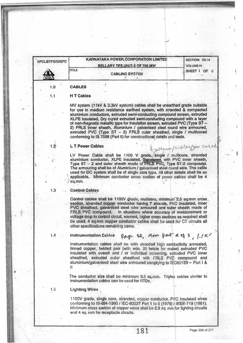
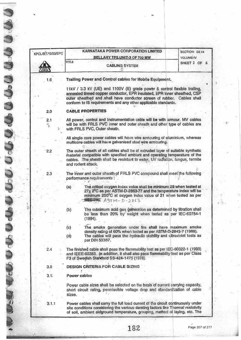
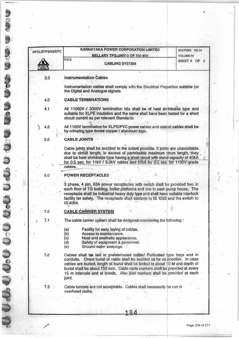
GENERAL TECHNICAL REQUIREMENTS FOR CABLES
Page 205 of 277
Page 206 of 277
Page 207 of 277

Page 208 of 277
Page 209 of 277

Page 210 of 277

Page 211 of 277
BHEL DOCUMENTS NO.: PE-TS-367-174-14000-A001
VOLUME II-B SECTION –D2
1X700 MW BELLARY 3 STPP REV. NO. 00 DATE: 29/05/13
BHEL – PS - PPEI: NOIDA, SECTOR-16A, U.P. – 201301
TITLE:
TECHNICAL SPECIFICATION FOR COOLING WATER OZONE GENERATION PLANT
GENERAL TECHNICAL REQUIREMENTS FOR PANELS, CABINETS & MISCELLANEOUS ELECTRICAL EQUIPMENTS
Page 212 of 277

Page 213 of 277

Page 214 of 277

Page 215 of 277
BHEL DOCUMENTS NO.: PE-TS-367-174-14000-A001
VOLUME II-B SECTION –D3
1X700 MW BELLARY 3 STPP REV. NO. 00 DATE: 29/05/13
BHEL – PS - PPEI: NOIDA, SECTOR-16A, U.P. – 201301
TITLE: TECHNICAL SPECIFICATION FOR
COOLING WATER OZONE GENERATION PLANT
SECTION – D3
GENERAL TECHNICAL REQUIREMENTS FOR C&I
Page 216 of 277

SPECIFICATION FORCONTROL & INSTRUMENTATION FOR AUX
PACKAGES
SPECIFICATION NO.:
VOLUME
SUB SECTION
REV. NO. DATE :
SHEET OF FOR
M N
O. P
EM
-666
6-0
GENERAL REQUIREMENT
1.0 Bidder shall provide complete and independent control & instrumentation system with all accessories, auxiliaries and associated equipments for the safe, efficient and reliable operation of auxiliary systems.
2.0 The quantity of instruments for auxiliary system shall be as per tender P &ID wherever provided of the respective system as a minimum, for bidding purpose. However, Bidder shall also include in his proposal all the instruments and devices that are needed for the completeness of the plant auxiliary system/ equipment supplied by the bidder, even if the same is not specifically appearing in the P & ID. During detail engineering if any additional instruments are required for safe & reliable operation of plant, bidder shall supply the same without any price implication.
3.0 Measuring instruments/equipment and subsystems offered by the bidder shall be from reputed experienced manufacturers of specified type and range of equipment, whose guaranteed and trouble free operation has been proven. Further all the instruments shall be of proven reliability, accuracy, and acceptable international standards and shall be subject to employer’s approval. All instrumentation equipment and accessories under this specification shall be furnished as per technical specification, ranges, makes/ numbers as approved by the employer’ during detail engineering.
4.0 The necessary root valves, impulse piping, drain cocks, gauge-zeroing cocks, valve manifold and all the other accessories required for mounting/ erection of these local instruments shall be furnished, even if not specifically asked for, on as required basis. The contacts of equipment mounted instruments; sensors, switches etc for external connection including spare contacts shall be wired out to suitably located junction boxes.
5.0 The customer specification attached as Specific Technical Requirement will supercede the Data sheets, if there is any mismatch.
Page 217 of 277

BHEL DOCUMENTS NO.: PE-TS-367-174-14000-A001
VOLUME II-B SECTION –D3
1X700 MW BELLARY 3 STPP REV. NO. 00 DATE: 29/05/13
BHEL – PS - PPEI: NOIDA, SECTOR-16A, U.P. – 201301
TITLE: TECHNICAL SPECIFICATION FOR
COOLING WATER OZONE GENERATION PLANT
GENERAL TECHNICAL REQUIREMENTS FOR LOCAL CONTROL PANEL
Page 218 of 277
DATA SHEET FOR LOCAL CONTROL PANEL
SPECIFICATION NO.: PE-TS-999-145-I990
VOLUME
SECTION
REV. NO. 00 DATE:
SHEET 1 OF 1TAG No. …………. Qty.................
Data Sheet A & B
DATA SHEET-A FOR LOCAL PANEL (TO BE FILLED BY PURCHASER)
DATA SHEET-B
(TO BE FILLED-UP BY BIDDER)
FOR
M N
O. P
EM-6
666-
0
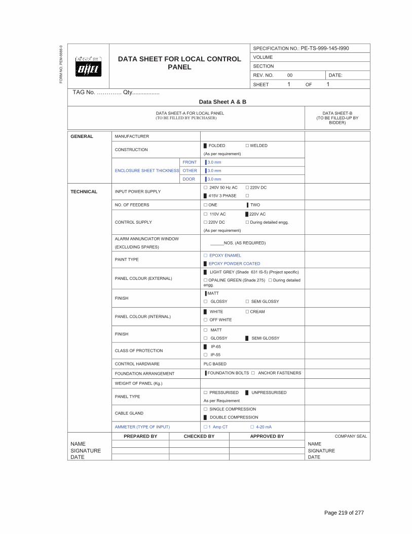
GENERAL MANUFACTURER
CONSTRUCTION � FOLDED � WELDED
(As per requirement)
ENCLOSURE SHEET THICKNESS
FRONT � 3.0 mm
OTHER � 3.0 mm
DOOR � 3.0 mm
TECHNICAL INPUT POWER SUPPLY � 240V 50 Hz AC � 220V DC
� 415V 3 PHASE �
NO. OF FEEDERS � ONE � TWO
CONTROL SUPPLY
� 110V AC � 220V AC
� 220V DC � During detailed engg.
(As per requirement)
ALARM ANNUNCIATOR WINDOW
(EXCLUDING SPARES) ______NOS. (AS REQUIRED)
PAINT TYPE � EPOXY ENAMEL
� EPOXY POWDER COATED
PANEL COLOUR (EXTERNAL) � LIGHT GREY (Shade 631 IS-5) (Project specific)
� OPALINE GREEN (Shade 275) � During detailed engg.
FINISH � MATT
� GLOSSY � SEMI GLOSSY
PANEL COLOUR (INTERNAL) � WHITE � CREAM
� OFF WHITE
FINISH � MATT
� GLOSSY � SEMI GLOSSY
CLASS OF PROTECTION � IP-65
� IP-55
CONTROL HARDWARE PLC BASED
FOUNDATION ARRANGEMENT � FOUNDATION BOLTS � ANCHOR FASTENERS
WEIGHT OF PANEL (Kg.)
PANEL TYPE � PRESSURISED � UNPRESSURISED
As per Requirement
CABLE GLAND � SINGLE COMPRESSION
� DOUBLE COMPRESSION
AMMETER (TYPE OF INPUT) � 1 Amp CT � 4-20 mA
PREPARED BY CHECKED BY APPROVED BY COMPANY SEAL
NAME NAME SIGNATURE SIGNATURE DATE DATE
Page 219 of 277

DATA SHEET FOR LOCAL PANELS
SPECIFICATION NO.:
VOLUME
SECTION
REV. NO. DATE:
SHEET 1 OF 1TAG No. …………. Qty.................
Data Sheet C
DATA SHEET-C FOR LOCAL PANEL (TO BE FILLED BY CONTRACTOR AFTER AWARD OF CONTRACT)
FOR
M N
O. P
EM
-666
6-0
GENERAL MANUFACTURER
CONSTRUCTION
ENCLOSURE SHEET THICKNESS
FRONT
OTHER
DOOR
TECHNICAL INPUT POWER SUPPLY
NO. OF FEEDERS
CONTROL SUPPLY
ALARM ANNUNCIATOR WINDOW
(EXCLUDING SPARES)
PAINT TYPE
PANEL COLOUR (EXTERNAL)
FINISH
PANEL COLOUR (INTERNAL)
FINISH
CLASS OF PROTECTION
CONTROL HARDWARE
FOUNDATION ARRANGEMENT
WEIGHT OF PANEL (Kg.)
PANEL TYPE
CABLE GLAND
AAMETER (TYPE OF INPUT)
PREPARED BY CHECKED BY APPROVED BY COMPANY SEAL
NAME NAME
SIGNATURE SIGNATURE
DATE DATE
Page 220 of 277

SPECIFICATION NO.: PES – 145 – 054A
VOLUME II B
SECTION D
REV. NO. 02 DATE : 22-02-2008
SPECIFICATION FORLOCAL PANELS
SHEET 1 OF 5FOR
M N
O. P
EM
-666
6-0
1.0 SCOPE This specification covers the Design, Manufacture, Inspection and Testing at the manufacturer’s works, proper packing for transportation and delivery to site of Local Panels required for control and monitoring of the Auxiliary Plant & Equipment.
2.0 CODES AND STANDARDS 2.1 All the equipments specified herein shall comply with the requirements of the latest issue of the relevant
National and International standards. 2.2 As a minimum requirement, the following standards shall be complied with:
a) IS-6005 : 1970 : Code of practice for phosphating of iron and steel. b) IS-5 : 1978 : Colours for ready mixed paints and enamels. c) IS-1248:1983 : Direct Acting Indicating Instruments. d) IS-13947 (Part-III):1993 : Rotary Cam Switches. e) IS-6875:1973 : Auxiliary relays. f) IS-8828:1993 : Circuit breaker for household and similar installations. g) IS-13947 (Part-I):1993 : Low Voltage switchgear & control gear : Part-I (General Rules) h) NFPA-496:1974 : Purged & Pressurised Enclosure for Electrical Equipment in
Hazardous Locations.
3.0 TECHNICAL REQUIREMENTS 3.1 Panel Construction 3.1.1 The local panels shall house the secondary instruments, annunciation system, Single loop controller,
Control switches / push buttons, indicating lamps, relays, timers and other devices required for operation and monitoring of the equipment locally.
3.1.2 The panels shall be of free standing type either welded construction on angle iron (minimum section of 50 x 50 x 4 mm) structure or folded construction by sheet metal formation depending upon the equipments to be mounted on it. The panels shall be robustly built and stiffners as necessary shall be provided.
3.1.3 The panel shall be suitably reinforced to ensure adequate support for all instruments mounted thereon. All welds on exposed panel surfaces shall be ground smooth.
3.1.4 The salient features of construction shall be:
Sheet material: Cold rolled sheet steel Frame thickness: Not less than 3.0mmEnclosure thickness: Not less than 2.5 mm for load bearing sections (Mounted with instruments), 1.6 mm for doors and Not less than 2.0 mm for others Panel Height: Not less than 2365 mm Gland plate thickness: 3.0mm Base channel: ISMC 100 with anti-vibration mounting & foundation bolts.
3.1.5 The panel shall be provided with rear doors with integral lockable handle. The door when locked shall be held at minimum three places.The door width shall not be more than 550mm.The doors shall be provided with suitable stiffners to prevent buckling. The handle shall be on the right side of the door. The door shall be removable type with concealed hinges to facilitate maintenance work. Suitable pocket inside the door shall be provided for keeping the drawings / documents.
[[[[[[[[[[[[[[[[[[[[[[[[[[[
3.1.6 Suitable neoprene gasket shall be provided on all doors and removable covers. Suitable ventilation louvers shall be provided at bottom and top of the doors covered with removable wire mesh.
Page 221 of 277
SPECIFICATION NO.: PES – 145 – 054A
VOLUME II B
SECTION D
REV. NO. 02 DATE : 22-02-2008
SPECIFICATION FORLOCAL PANELS
SHEET 2 OF 5FOR
M N
O. P
EM
-666
6-0
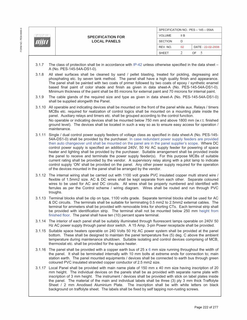
3.1.7 The class of protection shall be in accordance with IP-42 unless otherwise specified in the data sheet – A (No. PES-145-54A-DS1-0).
3.1.8 All steel surfaces shall be cleaned by sand / pellet blasting, treated for pickling, degreasing and phosphating etc. by seven tank method. The panel shall have a high quality finish and appearance. The panel shall be painted with two coats of primer followed by two coats of epoxy / synthetic enamel based final paint of color shade and finish as given in data sheet-A (No. PES-145-54A-DS1-0). Minimum thickness of the paint shall be 85 microns for external paint and 70 microns for internal paint.
3.1.9 The cable glands of the required size and type as given in data sheet-A (No. PES-145-54A-DS1-0) shall be supplied alongwith the Panel.
3.1.10 All operable and indicating devices shall be mounted on the front of the panel while aux. Relays / timers MCBs etc. required for realization of control logics shall be mounted on a mounting plate inside the panel. Auxiliary relays and timers etc. shall be grouped according to the control function.
No operable or indicating devices shall be mounted below 750 mm and above 1800 mm (w.r.t. finished ground level). The devices shall be located in such a way so as to ensure easy access for operation / maintenance.
3.1.11 Single / dual control power supply feeders of voltage class as specified in data sheet-A (No. PES-145-54A-DS1-0) shall be provided by the purchaser. In case redundant power supply feeders are provided then auto changeover unit shall be mounted on the panel are in the panel supplier’s scope. Where DC control power supply is specified an additional 240V, 50 Hz AC supply feeder for powering of space heater and lighting shall be provided by the purchaser. Suitable arrangement shall be provided inside the panel to receive and terminate the power supply feeder(s). For this purpose MCBs of suitable current rating shall be provided by the vendor. A supervisory relay along with a pilot lamp to indicate control supply ‘ON’ shall be provided on the panel. Any other power supply required for the operation of the devices mounted in the panel shall be arranged by the vendor.
3.1.12 The internal wiring shall be carried out with 1100 volt grade PVC insulated copper multi strand wire / flexible of 1.5mm2 size. AC & DC wires shall be kept separate from each other. Separate coloured wires to be used for AC and DC circuits. All wires shall be properly numbered and identified with ferrules as per the Control scheme / wiring diagram. Wires shall be routed and run through PVC troughs.
3.1.13 Terminal blocks shall be clip on type, 1100 volts grade. Separate terminal blocks shall be used for AC & DC circuits. The terminals shall be suitable for terminating 0.5 mm2 to 2.5mm2 external cables. The terminal for ammeters shall be provided with removable links for shorting CTs. Each terminal strip shall be provided with identification strip. The terminal shall not be mounted below 250 mm height from finished floor. The panel shall have ten (10) percent spare terminal.
3.1.14 The interior of each panel shall be suitably illuminated through fluorescent lamps operable on 240V 50 Hz AC power supply through panel door switch. A 15 Amp. 3-pin Power receptacle shall be provided.
3.1.15 Suitable space heaters operable on 240 Volts 50 Hz AC power system shall be provided at the panel bottom. These shall be designed to maintain the panel temperature five (5) deg. C above the ambient temperature during maintenance shutdown. Suitable isolating and control devices comprising of MCB, thermostat etc. shall be provided for the space heater.
3.1.16 The panel shall be provided with a copper earth bus of 25 x 6 mm size running throughout the width of the panel. It shall be terminated internally with 10 mm bolts at extreme ends for connection to; main station earth. The panel mounted equipments / devices shall be connected to earth bus through green coloured PVC insulated stranded copper conductor of 2.5 mm2 size.
3.1.17 Local Panel shall be provided with main name plate of 150 mm x 40 mm size having inscription of 20 mm height. The individual devices on the panels shall be as provided with separate name plate with inscription of 3 mm height. The instrument / devices shall be provided with stick on label plates inside the panel. The material of the main and individual labels shall be three (3) ply 3 mm thick Traffolyte Sheet / 2 mm Anodised Aluminium Plate. The inscription shall be with white letters on black background on traffolyte sheet. The labels shall be fixed by self tapping non-rusting screws.
Page 222 of 277

SPECIFICATION NO.: PES – 145 – 054A
VOLUME II B
SECTION D
REV. NO. 02 DATE : 22-02-2008
SPECIFICATION FORLOCAL PANELS
SHEET 3 OF 5FOR
M N
O. P
EM
-666
6-0
3.2 Hazardous Area Panel Requirement
3.2.1 The Local Panel located in hazardous area shall be pressurized as per NFPA-496 requirements to render it non-hazardous. Alarms shall be provided for local and remote annunciation when pressurisation falls below 2.5 mm of water column. Protection shall be of type Z of NFPA-496. It shall not be possible to switch ON the power of purged section unless it is purged as per the recommendation of NFPA-496. Vendor must provide a protective device on the panel to protect the panel from over pressurisation.
3.2.2 Vendor shall supply pressurisation kit consisting of valves, restriction orifices, dual filter regulation, pressure gauges, pressure switches, rotameter etc. Pressurisation kit shall be surface mounting on a metal board and located outside the local panel. Pressurisation kit shall further consist of solenoid valve flow switch, timer blow off safety device etc., so as to make purging fully automatic. However final start shall be manual. Panel protection against over pressure to be provided as per NFPA-496.
3.2.3 Pressurised local control panel pressurization kit assembly design shall provide minimum leakage flow through the Local Control Panel. Panel venting shall be as per NFPA-496.
3.2.4 All components in the local panel like indicating instruments, push buttons switches, lamps etc., which are required to be energized without panel pressurization or before completion of purge cycle shall be explosion proof as per NEMA-7 & suitable for area classification.
3.2.5 All push buttons etc. requiring frequent operation during machine running shall have good positive sealing. Weatherproof housing or cover to be provided wherever necessary. Vendor shall provide pressurisation bypass switch outside explosion proof enclosure of pressurized panel with lamp indication. This shall be used only during maintenance. All hinges, screws, other non-painted metallic parts shall be of stainless steel material.
3.2.6 Provision to switch off manually all types of power shall be provided in the panel. In addition, it shall also be possible to switch off power circuits / components which are powered from motor control centre or control room manually in case of pressurization failure. All such cables from MCC and main control room shall be terminated in explosion proof boxes (NEMA-7).
3.3 Control & Monitoring devices
3.3.1 Instruments like Indicators, recorders, single loop controllers etc. as applicable and specified elsewhere for the plant / equipment shall be supplied and mounted on the panel.
3.3.2 Alarm Annunciator System It shall be solid state discrete facia type having a sequence of ISA-S18.1A or as specified, opaque facia
windows of 70 mm x 50 mm size, having two (2) lamps per window, and hooter of 10W, and provision for repeat group alarm at remote. The annunciator shall be provided with ten (10) percent spare windows or minimum two (2) windows along with electronics.
3.3.3 Relays
The relays shall be electromagnetic type suitable for specified control supply. Its contact configuration and rating shall be suitable for the specified control function. However minimum contact rating shall be 5 Amp AC & 2 Amp DC as applicable. There shall be ten (10) percent spare contacts.
3.3.4 Timers The timers shall be electronic type suitable for specified control supply. Its contact configuration and
rating shall be suitable for the specified control function. However, minimum contact rating shall be 5 Amp AC & 2 Amp DC as applicable.
3.3.5 Control / Selector Switches Switches shall be Rotary Cam type with minimum of 5 Amps AC & 2 Amp DC continuous current rating.
Selector switches shall be stay put type while control switches shall be spring-return-to-neutral type. Contact configuration and rating shall be as per the control function requirement. The switches shall be lockable type wherever specified. Each switch shall be provided with engraved plates indicating the switch position / functions.
Page 223 of 277

SPECIFICATION NO.: PES – 145 – 054A
VOLUME II B
SECTION D
REV. NO. 02 DATE : 22-02-2008
SPECIFICATION FORLOCAL PANELS
SHEET 4 OF 5FOR
M N
O. P
EM
-666
6-0
3.3.6 Push Buttons / Indicating Lights The push buttons shall be momentary action self-resetting type, however stop P.B. for unidirectional
drives shall be provided with manual reset facility. Its contact configuration & rating shall be as required for the control function but minimum 2 NO + 2 NC of 5 Amp. AC rating. It shall have round coloured projecting tab and engraved escutcheon plate / inscription plate. Colour coding of push buttons shall be as under:
RED Motor OFF / Valve CLOSE YELLOW Alarm acknowledge. GREEN Motor ON / Valve OPEN BLACK Lamp test
Indicating lights shall be suitable for direct connections across specified power supplies. It shall be fitted with built in resistance to prevent circuit tripping on shorting of lamp filament. It shall be fitted with LED cluster type lamp replaceable from front.
GREEN Motor OFF / Valve CLOSED condition AMBER Motor tripped condition. RED Motor ON / Valve OPEN condition WHITE Normal / healthy condition 3.3.7 Ammeters Ammeter shall be 96 x 96 mm size, 90 deg. deflection, 1.5% accuracy, 1 Amp. CT operated or with
4-20mA input and Flush mounting type as called for in the data sheet-A (No. PES-145-54A-DS1-0). Ammeters for motors shall have six (6) times folded scale at upper end to enable motor starting current indication.
3.3.8 Miniature Circuit Breaker (MCB)
These shall be instantaneous magnetic trip type for short circuit in addition to current time inverse delayed thermal trip feature for over current protection. The housing of MCB shall be made of non-ignitable, high impact material. It shall have minimum short circuit rating of 9 KA for AC Voltages and 4 KA for DC Voltages.
3.3.9 Makes of various instruments / devices shall be as given below
1. Alarm Annunciators : Procon / IIC 2. Ammeters : AEP / IMP 3. Control / Selector Switches : Alsthom / Kaycee / Siemens / L&T 4. Push Buttons / Indicating Lamps : Siemens / L&T / Teknic / Alsthom 5. Auxiliary Relays : Jyoti / Siemens / L&T / OEN 6. Timers : L&T / Alsthom / Bhartiya Cutler Hammer 7. MCBs : S&S Power Engg. / Indo Asian / MDS 8. Terminal Blocks : Jyoti / Elmex
4.0 TESTING AND INSPECTION
4.1 The bidder shall adopt suitable quality assurance program to ensure that the equipments offered will meet the specification requirements in full.
4.2 BHEL’s standard Quality Plan for LCP is enclosed with the specification. The bidder shall furnish his acceptance to BHEL’s QP and submit the signed and stamped copy of QP along with the offer.
4.3 The vendor shall conduct the following tests as a minimum requirement:
4.3.1 Routine Tests 1. High Voltage (H.V.)2. Insulation Resistance (I.R.) 3. Functional
4.3.2 Type Tests
1. Enclosure Class Test
Page 224 of 277
SPECIFICATION NO.: PES – 145 – 054A
VOLUME II B
SECTION D
REV. NO. 02 DATE : 22-02-2008
SPECIFICATION FORLOCAL PANELS
SHEET 5 OF 5FOR
M N
O. P
EM
-666
6-0
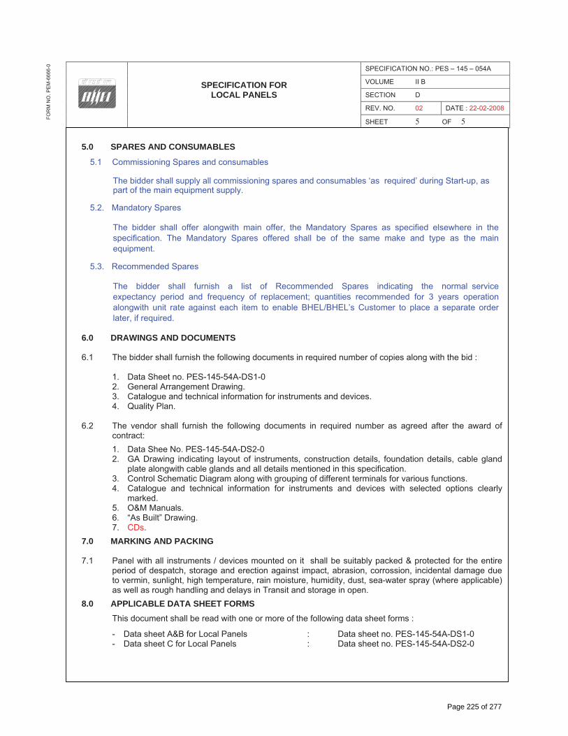
5.0 SPARES AND CONSUMABLES
5.1 Commissioning Spares and consumables
The bidder shall supply all commissioning spares and consumables ‘as required’ during Start-up, as part of the main equipment supply.
5.2. Mandatory Spares
The bidder shall offer alongwith main offer, the Mandatory Spares as specified elsewhere in the specification. The Mandatory Spares offered shall be of the same make and type as the main equipment.
5.3. Recommended Spares
The bidder shall furnish a list of Recommended Spares indicating the normal service expectancy period and frequency of replacement; quantities recommended for 3 years operation alongwith unit rate against each item to enable BHEL/BHEL’s Customer to place a separate order later, if required.
6.0 DRAWINGS AND DOCUMENTS
6.1 The bidder shall furnish the following documents in required number of copies along with the bid :
1. Data Sheet no. PES-145-54A-DS1-0 2. General Arrangement Drawing. 3. Catalogue and technical information for instruments and devices. 4. Quality Plan.
6.2 The vendor shall furnish the following documents in required number as agreed after the award of contract:1. Data Shee No. PES-145-54A-DS2-0 2. GA Drawing indicating layout of instruments, construction details, foundation details, cable gland
plate alongwith cable glands and all details mentioned in this specification. 3. Control Schematic Diagram along with grouping of different terminals for various functions. 4. Catalogue and technical information for instruments and devices with selected options clearly
marked.5. O&M Manuals. 6. “As Built” Drawing. 7. CDs.
7.0 MARKING AND PACKING
7.1 Panel with all instruments / devices mounted on it shall be suitably packed & protected for the entire period of despatch, storage and erection against impact, abrasion, corrossion, incidental damage due to vermin, sunlight, high temperature, rain moisture, humidity, dust, sea-water spray (where applicable) as well as rough handling and delays in Transit and storage in open.
8.0 APPLICABLE DATA SHEET FORMS This document shall be read with one or more of the following data sheet forms :
- Data sheet A&B for Local Panels : Data sheet no. PES-145-54A-DS1-0 - Data sheet C for Local Panels : Data sheet no. PES-145-54A-DS2-0
Page 225 of 277

BHEL DOCUMENTS NO.: PE-TS-367-174-14000-A001
VOLUME II-B SECTION –D3
1X700 MW BELLARY 3 STPP REV. NO. 00 DATE: 29/05/13
BHEL – PS - PPEI: NOIDA, SECTOR-16A, U.P. – 201301
TITLE: TECHNICAL SPECIFICATION FOR
COOLING WATER OZONE GENERATION PLANT
GENERAL TECHNICAL REQUIREMENTS FOR INSTRUMENTS
Page 226 of 277
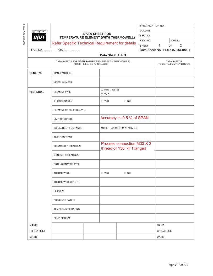
DATA SHEET FOR TEMPERATURE ELEMENT (WITH THERMOWELL)
SPECIFICATION NO.:
VOLUME
SECTION
REV. NO. DATE:
SHEET 1 OF 2TAG No. …………. Qty................. Data Sheet No.: PES-145-03A-DS1-0
Data Sheet A & B
DATA SHEET-A FOR TEMPERATURE ELEMENT (WITH THERMOWELL) (TO BE FILLED BY PURCHASER)
DATA SHEET-B (TO BE FILLED-UP BY BIDDER)
FOR
M N
O. P
EM
-666
6-0
GENERAL MANUFACTURER
MODEL NUMBER
TECHNICAL ELEMENT TYPE � RTD (3 WIRE)
� T / C
T / C GROUNDED � YES � NO
ELEMENT THICKNESS (AWG)
LIMIT OF ERROR
INSULATION RESISTANCE MORE THAN 5M OHM AT 100V DC
TIME CONSTANT
MOUNTING THREAD SIZE
CONDUIT THREAD SIZE
EXTENSION WIRE TYPE
THERMOWELL � YES � NO
THERMOWELL LENGTH
LINE SIZE
PRESSURE RATING
TEMPERATURE RATING
FLUID MEDIUM
NAME NAME
SIGNATURE SIGNATURE
DATE DATE
Accuracy +- 0.5 % of SPAN
Process connection M33 X 2thread or 150 RF Flanged
Refer Specific Technical Requirement for details
Page 227 of 277

DATA SHEET FOR TEMPERATURE TRANSMITTER
SPECIFICATION NO.:
VOLUME
SECTION
REV. NO. DATE:
SHEET 1 OF 2TAG No. …………. Qty................. Data Sheet No.: PES-145-03A-DS1-0
Data Sheet C
DATA SHEET-C FOR TEMPERATURE ELEMENT (WITH THERMOWELL) (TO BE FILLED BY CONTRACTOR AFTER AWARD OF CONTRACT)
FOR
M N
O. P
EM
-666
6-0
GENERAL MANUFACTURER
MODEL NUMBER
TECHNICAL ELEMENT TYPE
T / C GROUNDED
ELEMENT THICKNESS (AWG)
LIMIT OF ERROR
INSULATION RESISTANCE
TIME CONSTANT
MOUNTING THREAD SIZE
CONDUIT THREAD SIZE
EXTENSION WIRE TYPE
THERMOWELL
THERMOWELL LENGTH
LINE SIZE
PRESSURE RATING
TEMPERATURE RATING
FLUID MEDIUM
NAME NAME
SIGNATURE SIGNATURE
DATE DATE
Page 228 of 277

SPECIFICATION FOR TEMPERATURE ELEMENT FOR AUX PACKAGE
SPECIFICATION NO.: PES – 145 – 003A
VOLUME II B
SECTION D
REV. NO. 01 DATE : 27.07.94
SHEET 1 OF 3FOR
M N
O. P
EM-6
666-
0
1.0 TECHNICAL REQUIREMENTS
1.1 General
i) The temperature sensor elements shall be duplex type either thermocouple (T/C) or resistance temperature detector (RTD). Unless otherwise specified, the type of sensors for different applications shall be as follows:
ii) Nickel Chromium Nickel T/C medium temp. range (250°C to 600°C)
iii) Platinum-Rhodium Platinum High temp. range (600°C and above). Type S/R/B.
iv) Platinum RTD Low temperature & high accuracy (-50°C to 250°C).
1.2 Process Parameters
The instrument shall be suitable for a Process Parameters given in the instrument data sheet.
1.3 Thermocouple Wire Size
The thermocouple wire size for a given temperature application shall be as per table - 3.1A of ASME PTC 19.3 - 1974.
1.4 Sensor Grounding
As per instrument data sheet.
1.5 Sensor Protective Sheath & Wire Insulation
The sensor protective sheath shall be 8mm OD 316 SS seamless tube using compacted magnesium oxide packing/porcelain for insulation.
1.6 Sensor Characteristics
Thermocouple calibration characteristics i.e. temperature vs. milli volt or resistance shall be as per the applicable Indian Standards (IS-2054 for thermocouple ‘K’ type, IS-2055 for Pt.Rd.Pt.), RTD type of sensor calibration i.e. temperature vs. resistance shall be as per applicable Indian Standard (IS-2848).
1.7 Sensor Accuracy Limits
T/C sensor limiting accuracy shall be as per table 3.2A of ASME PTC 19.3 - 1974. RTD sensor accuracy shall be as per table 9.1 of ASME PTC - 19.3 - 74.
1.8 Insulation Resistance
Insulation resistance of RTD leads w.r.t. body shall be more than 5 mega ohms at 100V DC.
1.9 End Connection
The sensor assemblies shall have screwed M33 x 2 end connection. Specific design requirements of pressure, temperature and end connection type for a given application are indicated in the instrument data sheet.
Page 229 of 277

SPECIFICATION FOR TEMPERATURE ELEMENT FOR AUX PACKAGE
SPECIFICATION NO.: PES – 145 – 003A
VOLUME II B
SECTION D
REV. NO. 01 DATE : 27.07.94
SHEET 2 OF 3FOR
M N
O. P
EM-6
666-
0
1.10 Terminal Head
The terminal head cover shall be screwed type design having gasket with small flexible chain attached between fixed portion and head cover.
1.10.1 Terminal Head Enclosure
The terminal head enclosure shall be dust, weather proof and water proof as per NEMA-4 classification unless specified otherwise.
1.10.2 Terminals
The terminal head shall have provision of screwed terminal of 1.5 mm2 size for external connection. The terminals shall be suitably marked ‘+ve’ & ‘-ve’ for thermocouple and ‘Lo’, ‘Hi’ and “C’ for three wire RTD.
1.11 Cable Entry
Cable gland complete with neoprene gromet suitable for PVC cable with maximum diameter of 17.5mm shall be provided for cable entry. The actual size of cable shall be indicated during the contract stage. Separate cable entry and cable glands shall be provided for both the elements.
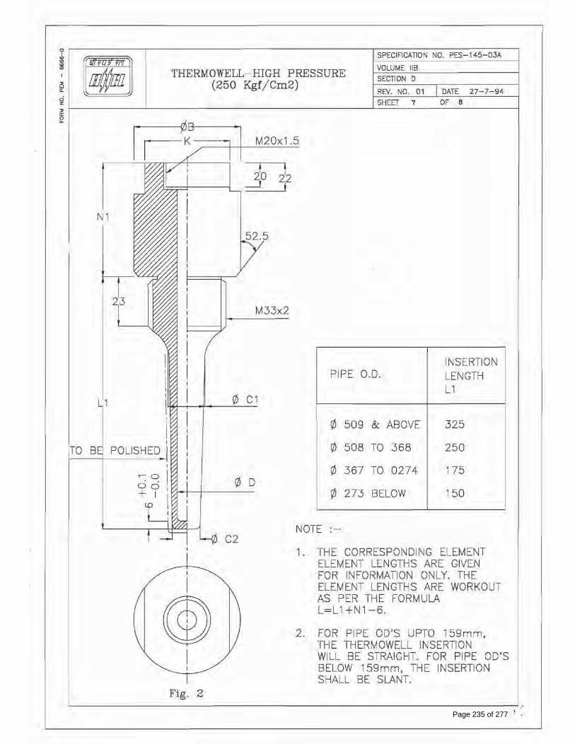
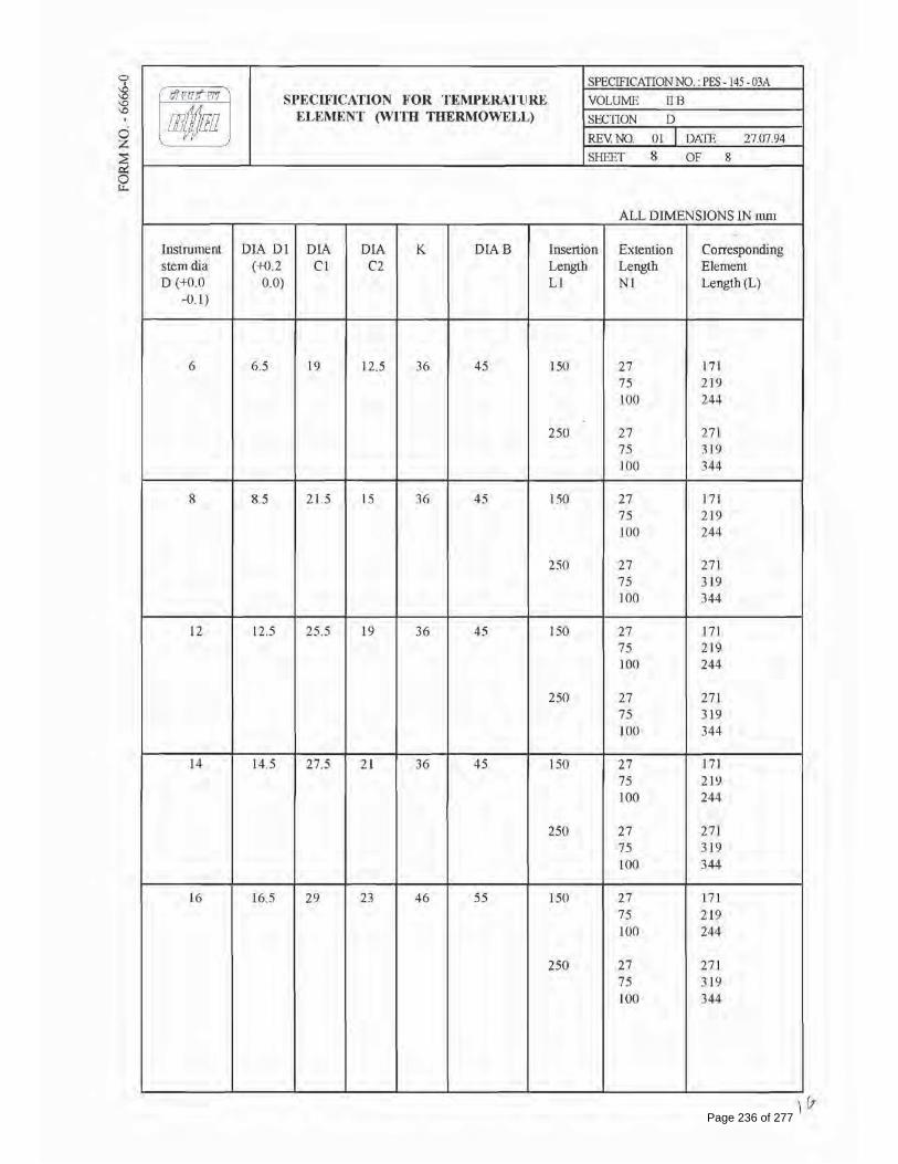
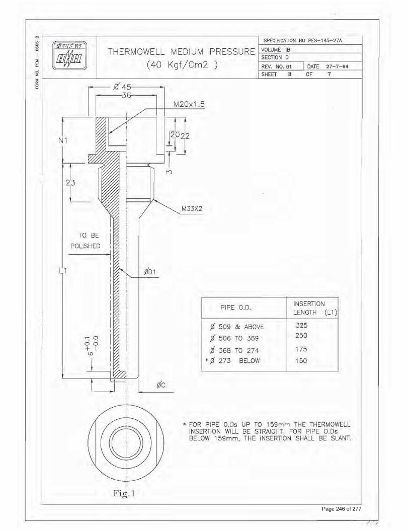
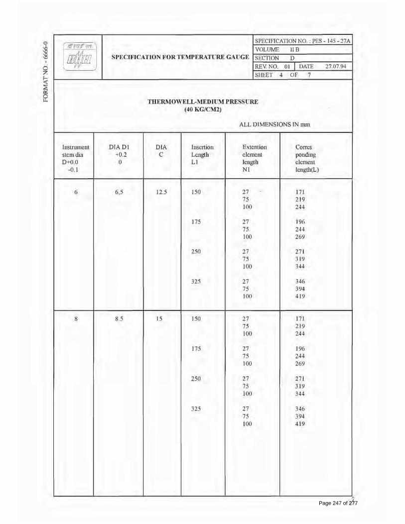
1.12 Thermowell and its material
Temperature element shall be supplied along with the thermowell. The thermowell shall be of tungstion carbide for mill air temperature and for rest of the applications of AISI 316SS shall be machined out of solid bar stock and designed to suit the process conditions. For detail of the thermowell, see enclosed drawing.
1.12.1 Internal Construction
Sensor assemblies shall preferably be metal sheathed with spring load on to the thermowell tip for better response. The sheathed sensor assembly shall be replaceable (in-situ) type without removal of thermowell.
1.12.2 Compensating cable should be used for connecting elements to secondary Instruments/Device unless there is specific requirement for cold junction compensation. Field mounted cold junction compensation box as per NEMA-4 shall be provided for all thermocouples. The CJC box shall have automatic temperature control at reference junction temperature of 60°C. Each CJC box shall be provided with duplex RTD for remote monitoring.
2.0 TESTING
2.1 The bidder shall adopt suitable quality assurance program to ensure that the equipments offered will meet the specification requirements in full.
2.2 The vendor shall conduct following tests as a minimum requirement and shall furnish test certificate thereof, for BHEL's approval before despatch of the same.
2.2.1 Physical dimension of the sensor assemblies as per approved drawing.
2.2.2 Electrical characterstic of sensor such as continuity of the thermocouple wires, and insulation resistance of the RTD leads w.r.t. body.
Page 230 of 277
SPECIFICATION FOR TEMPERATURE ELEMENT FOR AUX PACKAGE
SPECIFICATION NO.: PES – 145 – 003A
VOLUME II B
SECTION D
REV. NO. 01 DATE : 27.07.94
SHEET 3 OF 3FOR
M N
O. P
EM-6
666-
0
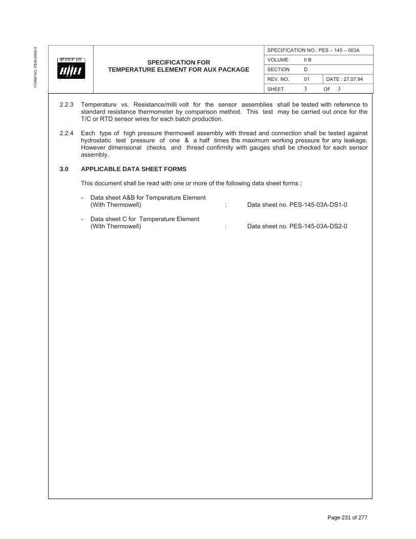
2.2.3 Temperature vs. Resistance/milli volt for the sensor assemblies shall be tested with reference to standard resistance thermometer by comparison method. This test may be carried out once for the T/C or RTD sensor wires for each batch production.
2.2.4 Each type of high pressure thermowell assembly with thread and connection shall be tested against hydrostatic test pressure of one & a half times the maximum working pressure for any leakage. However dimensional checks and thread confirmity with gauges shall be checked for each sensor assembly.
3.0 APPLICABLE DATA SHEET FORMS
This document shall be read with one or more of the following data sheet forms :
- Data sheet A&B for Temperature Element (With Thermowell) : Data sheet no. PES-145-03A-DS1-0
- Data sheet C for Temperature Element (With Thermowell) : Data sheet no. PES-145-03A-DS2-0
Page 231 of 277

Page 232 of 277
Page 233 of 277
Page 234 of 277
Page 235 of 277
Page 236 of 277

CHECK LIST FOR PRESSURE / DIFFERENTIAL PRESSURE GAUGE
(MECHANICAL AUXILIARY PACKAGES)
SPECIFICATION NO.: PE-TS-375-145-I054 VOLUME SECTIONREV. NO. 00 DATE: 15.02.2012SHEET 16 OF 16
FOR
M N
O. P
EM
-666
6-0
SLNO
TESTS/CHECKS QUANTM OF CHECK
REFERENCE DOC. ACCEPTANCE NORMS
AGENCY REMARKS
P W V 1.0 CHECK FOR
APPROVEDTECHINCAL REQUIREMENT/ DATA SHEET
MFR TO CARRY OUT ROUTINE TEST ON 100%. WHEN MATL CORELATION ARE NOT AVAILABLEMFR’SCOMPLIANCE TO BE PROVIDED
1.1 DIAL SIZE 100% M C C
1.2 MODEL NO/TAG NO 100% M C C 1.3 RANGE/SCALE 100% M C C 1.4 END CONNECTION 100% M C C 1.5 SWITCH CONTACT RATING & NOS
100% M C C
2.0 CALIBRATION
2.1 ACCURACY 100% M C B 2.2 REPEATABILITY (FOR SWITCH)
100% M C B
2.3 SET POINT ADJUSTMENT FOR SWITCH
100% M C C
3.0 OVER PRESSURE & LEAK TEST
100% M C C
4.0 OPERATION OF PR. RELEIF DEVICE
ONE PER TYPE
M C C
5.0 REVIEW OF T.C. FOR MATERIAL OF--
5.1 SENSOR
FOR LOT
- - B
5.2 MOVEMENT - - B 5.3 PROCESS CONNECTION - - B
5.4 HOUSING - - B 6.0 REVIEW OF T.C. FOR
DEGREE OF PROTECTION TYPE TEST - - B
7.0 REVIEW OF T.C. FOR CONTACT RATING OF SWITCH
ONE PER TYPE
- - B
8.0 ACCESSORIES AS APPLICABLE
100% M C C
LEGEND:M: MANUFACTURER/ SUB CONTRACTOR, C: CONTRACTOR/ NOMINATED INSP AGENCY, B: BHEL. P: PERFORM, W: WITNESS, V: VERIFICATION.
NOTE: CONTRACTOR TO PROVIDE COMPLIANCE CERTIFICATE FOR TESTS/CHECKS VERIFIED BY CONTRACTOR AND SUBMIT THE SAME ALONGWITH TEST CERTIFICATES TO BE VERIFIED BY BHEL.
Page 237 of 277

DATA SHEET FOR PRESSURE / DIFFERENTIAL PRESSURE GAUGE
SPECIFICATION NO.:
VOLUME
SECTION
REV. NO. DATE:
SHEET 1 OF 1TAG No. …………. Qty................. Data Sheet No.: PE-DC-999-145-I026
Data Sheet A & B
DATA SHEET-A FOR PRESSURE / DIFFERENTIAL PRESSURE GAUGE (TO BE FILLED BY PURCHASER)
DATA SHEET-B
(TO BE FILLED-UP BY BIDDER)
FOR
M N
O. P
EM
-666
6-0
GENERAL MANUFACTURER
MODEL NUMBER
TECHNICAL PRESSURE ELEMENT � BOURDON � DIAPHRAGM � BELLOW
MATERIAL
SENSING ELEMENT – AISI 316 SS
MOVEMENT – AISI 304 SS
CASING – � DIE CAST AL � SS
ENCLOSURE
� IP-55
� IP-65
� FUEL GAS HAZARDOUS APPL. EXPL. PROOF
DIAL
SIZE: � 100MM � 150MM
COLOR: WHITE
NUMERALS: BLACK
SCALE: � LINEAR � SQUARE ROOT
CASE COLOUR : BLACK
ADJUSTMENT � EXT. MICROMETER SCREW
� INT. MICRO SCREW
MOUNTING � LOCAL � PANEL OR RACK
OVER RANGE PROTECTION
� 150% OF MAX. PRESSURE
� 125% ABOVE 150 KG/CM2 FSD
� AS REQUIRED
BLOW OUT DISC SUITABLE MATERIAL
SWITCHING FACILITY
NO./TYPE OF CONTACTS COJNTACT RATINGS SETTING RANGE REPEATABLITY POWER SUPPLY
NOT REQUIRED
PERFORMANCE ACCURACY + 0.5% OR BETTER OF FULL SCALE DEFLECTION
CONNECTION PROCESS AS APLLICABLE
LOCATION � BACK � BOTTOM � AS REQUIRED
ACCESSORIES NAME PLATE / METAL TAG SS
MOUNTING
� WALL �PIPE – U CLAMPS & BOLTS
� PANEL / RACK
� AS REQUIRED
OTHER AS PER ENCLOSED DIAGRAM OR CUSTOMER SPECIFICATION
NAME NAME
SIGNATURE SIGNATURE
DATE DATE
Refer Specific Technical Requirement for details
Refer Specific Technical Requirement for details
Refer Specific Technical Requirement fordetails
Refer Specific TechnicalRequirement for details
Page 238 of 277

DATA SHEET FOR PRESSURE / DIFFERENTIAL PRESSURE GAUGE
SPECIFICATION NO.:
VOLUME
SECTION
REV. NO. DATE:
SHEET 1 OF 1TAG No. …………. Qty................. Data Sheet No.: PE-DC-999-145-I026
Data Sheet C
DATA SHEET-C FOR PRESSURE / DIFFERENTIAL PRESSURE GAUGE (TO BE FILLED BY CONTRACTOR AFTER AWARD OF CONTRACT)
FOR
M N
O. P
EM
-666
6-0
GENERAL MANUFACTURER
MODEL NUMBER
TECHNICAL PRESSURE ELEMENT
MATERIAL
ENCLOSURE
DIAL
CASE
ADJUSTMENT
MOUNTING
OVER RANGE PROTECTION
BLOW OUT DISC
SETTING RANGE
PERFORMANCE ACCURACY CONNECTION PROCESS
LOCATION
ACCESSORIES NAME PLATE / METAL TAG
MOUNTING
OTHER
NAME NAME
SIGNATURE SIGNATURE
DATE DATE
Page 239 of 277

DATA SHEET FOR PRESSURE / DIFFERENTIAL PRESSURE TRANSMITTER
SPECIFICATION NO.:
VOLUME
SECTION
REV. NO. DATE:
SHEET 1 OF 4TAG No. …………. Qty................. Data Sheet No.: PES-145-01-DS1-0
Data Sheet A & B
DATA SHEET-A FOR PRESSURE / DIFFERENTIAL PRESSURE TRANSMITTER (TO BE FILLED BY PURCHASER)
DATA SHEET-B (TO BE FILLED-UP BY BIDDER)
FOR
M N
O. P
EM
-666
6-0
GENERAL MANUFACTURER
MODEL NUMBER
TECHNICAL TYPE � INDUCTANCE � CAPACITANCE
� STRAIN GAUGE �
POWER SUPPLY 24V DC
TRANSMITTER MEASUREMENT � PRESSURE � DIFF. PRESSURE
OUTPUT SIGNAL 4-20MA
NO. OF WIRE TWO
ACCURACY ± 0.5% OF SPAN
LINEARITY, HYSTERISIS, DEAD BAND AND REPEATABILITY ± 0.1% OF SPAN
STABILITY ± 0.25% OF SPAN OR BETTER FOR 6 MONTHS
SENSITIVITY ± 0.05% OF SPAN
MATERIAL
A) BODY FORGED CARBON STEEL
B) ELEMENT 316 SS
C) SEAL TEFLON
CONTINUOUSLY ADJUSTABLE SPAN AND ZERO ADJUSTMENT PROVIDED � YES � NO
MOUNTING � WALL/PIPE STAND
� TRANSMITTER RACK
ENCLOSURE � NEMA-4 � NEMA-7
TURN DOWN RATIO TO BE SPECIFIED BY BIDDER
INSULATION RESISTANCE TO BE SPECIFIED BY BIDDER
ZERO SUPPRESSION RANGE TO BE SPECIFIED BY BIDDER
ZERO ELEVATION RANGE TO BE SPECIFIED BY BIDDER
INTEGRAL INDICATOR � YES � NO
Page 240 of 277

DATA SHEET FOR PRESSURE / DIFFERENTIAL PRESSURE TRANSMITTER
SPECIFICATION NO.:
VOLUME
SECTION
REV. NO. DATE:
SHEET 2 OF 4TAG No. …………. Qty................. Data Sheet No.: PES-145-01-DS1-0
Data Sheet A & B
DATA SHEET-A FOR PRESSURE / DIFFERENTIAL PRESSURE TRANSMITTER (TO BE FILLED BY PURCHASER)
DATA SHEET-B (TO BE FILLED-UP BY BIDDER)
FOR
M N
O. P
EM
-666
6-0
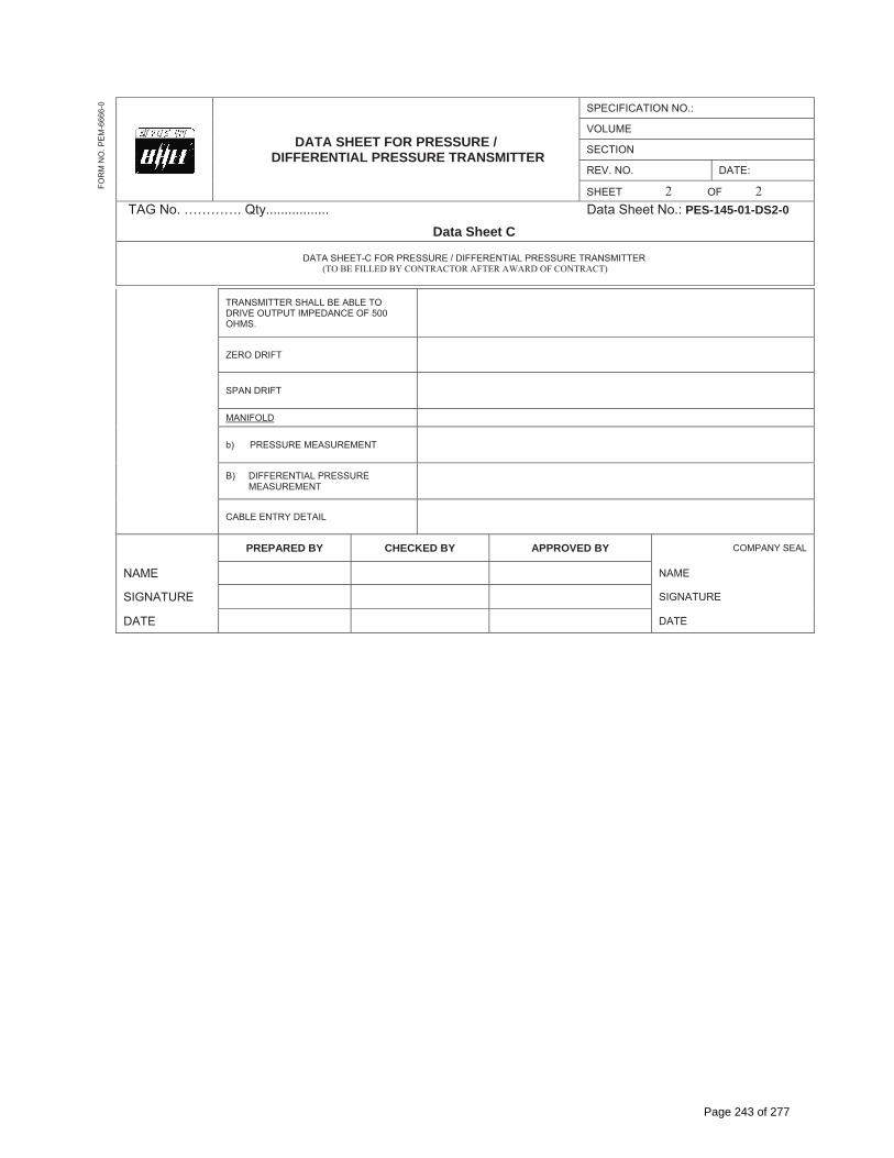
TRANSMITTER SHALL BE ABLE TO DRIVE OUTPUT IMPEDANCE OF 500 OHMS.
YES
ZERO DRIFT < 0.1%
SPAN DRIFT < 0.1%
MANIFOLD
a) PRESSURE MEASUREMENT 3 WAY
B) DIFFERENTIAL PRESSURE MEASUREMENT 5 WAY
CABLE ENTRY DETAIL SUITABLE FOR DIA OF 17.5 mm
PREPARED BY CHECKED BY APPROVED BY COMPANY SEAL
NAME NAME
SIGNATURE SIGNATURE
DATE DATE
Page 241 of 277

DATA SHEET FOR PRESSURE / DIFFERENTIAL PRESSURE TRANSMITTER
SPECIFICATION NO.:
VOLUME
SECTION
REV. NO. DATE:
SHEET 1 OF 2TAG No. …………. Qty................. Data Sheet No.: PES-145-01-DS2-0
Data Sheet C
DATA SHEET-C FOR PRESSURE / DIFFERENTIAL PRESSURE TRANSMITTER (TO BE FILLED BY CONTRACTOR AFTER AWARD OF CONTRACT)
FOR
M N
O. P
EM
-666
6-0
GENERAL MANUFACTURER
MODEL NUMBER
TECHNICAL TYPE
POWER SUPPLY
TRANSMITTER MEASUREMENT
OUTPUT SIGNAL
NO. OF WIRE
ACCURACY
LINEARITY, HYSTERISIS, DEAD BAND AND REPEATABILITY
STABILITY
SENSITIVITY
MATERIAL
A) BODY
B) ELEMENT
C) SEAL
CONTINUOUSLY ADJUSTABLE SPAN AND ZERO ADJUSTMENT PROVIDED
MOUNTING
ENCLOSURE
TURN DOWN RATIO
INSULATION RESISTANCE
ZERO SUPPRESSION RANGE
ZERO ELEVATION RANGE
INTEGRAL INDICATOR
Page 242 of 277
DATA SHEET FOR PRESSURE / DIFFERENTIAL PRESSURE TRANSMITTER
SPECIFICATION NO.:
VOLUME
SECTION
REV. NO. DATE:
SHEET 2 OF 2TAG No. …………. Qty................. Data Sheet No.: PES-145-01-DS2-0
Data Sheet C
DATA SHEET-C FOR PRESSURE / DIFFERENTIAL PRESSURE TRANSMITTER (TO BE FILLED BY CONTRACTOR AFTER AWARD OF CONTRACT)
FOR
M N
O. P
EM
-666
6-0
TRANSMITTER SHALL BE ABLE TO DRIVE OUTPUT IMPEDANCE OF 500 OHMS.
ZERO DRIFT
SPAN DRIFT
MANIFOLD
b) PRESSURE MEASUREMENT
B) DIFFERENTIAL PRESSURE MEASUREMENT
CABLE ENTRY DETAIL
PREPARED BY CHECKED BY APPROVED BY COMPANY SEAL
NAME NAME
SIGNATURE SIGNATURE
DATE DATE
Page 243 of 277
DATA SHEET FOR TEMPERATURE GAUGE
SPECIFICATION NO.:
VOLUME
SECTION
REV. NO. DATE:
SHEET 1 OF 2TAG No. …………. Qty................. Data Sheet No.: PES-145-27-DS1-0
Data Sheet A & B
DATA SHEET-A FOR TEMPERATURE GAUGE (TO BE FILLED BY PURCHASER)
DATA SHEET-B (TO BE FILLED-UP BY BIDDER)
FOR
M N
O. P
EM
-666
6-0
GENERAL MANUFACTURER
MODEL NUMBER
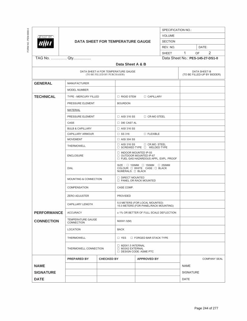
TECHNICAL TYPE - MERCURY FILLED � RIGID STEM � CAPILLARY
PRESSURE ELEMENT BOURDON
MATERIAL
PRESSURE ELEMENT � AISI 316 SS � CR-MO STEEL
CASE � DIE CAST AL
BULB & CAPILLARY � AISI 316 SS
CAPILLARY ARMOUR � SS 316 � FLEXIBLE
MOVEMENT � AISI 304 SS
THERMOWELL � AISI 316 SS � CR.MO. STEEL � SCREWED TYPE � WELDED TYPE
ENCLOSURE� INDOOR MOUNTED IP-55 � OUTDOOR MOUNTED IP-67 � FUEL GAS HAZARDOUS APPL. EXPL. PROOF
DIAL SIZE : � 100MM � 150MM � 250MM COLOUR: � WHITE CASE : � BLACK NUMERALS: � BLACK
MOUNTING & CONNECTION � DIRECT MOUNTED � PANEL OR RACK MOUNTED
COMPENSATION CASE COMP.
ZERO ADJUSTER PROVIDED
CAPILLARY LENGTH 5.0 METERS (FOR LOCAL MOUNTED) 15.0 METERS (FOR PANEL/RACK MOUNTING)
PERFORMANCE ACCURACY ± 1% OR BETTER OF FULL SCALE DEFLECTION
CONNECTION TEMPERATURE GAUGE CONNECTION M20X1.5(M)
LOCATION BACK
THERMOWELL � YES � FORGED BAR STACK TYPE
THERMOWELL CONNECTION � M20X1.5 INTERNAL � M33X2 EXTERNAL � DESIGN CODE: ASME PTC
PREPARED BY CHECKED BY APPROVED BY COMPANY SEAL
NAME NAME
SIGNATURE SIGNATURE
DATE DATE
Page 244 of 277
DATA SHEET FOR PRESSURE / DIFFERENTIAL PRESSURE TRANSMITTER
SPECIFICATION NO.:
VOLUME
SECTION
REV. NO. DATE:
SHEET 1 OF 2TAG No. …………. Qty................. Data Sheet No.: PES-145-27-DS2-0
Data Sheet C
DATA SHEET-C FOR TEMPERATURE GAUGE (TO BE FILLED BY CONTRACTOR AFTER AWARD OF CONTRACT)
FOR
M N
O. P
EM
-666
6-0
GENERAL MANUFACTURER
MODEL NUMBER
TECHNICAL TYPE - MERCURY FILLED
PRESSURE ELEMENT
MATERIAL
PRESSURE ELEMENT
CASE
BULB & CAPILLARY
CAPILLARY ARMOUR
MOVEMENT
THERMOWELL
ENCLOSURE
DIAL
MOUNTING & CONNECTION
COMPENSATION
ZERO ADJUSTER
CAPILLARY LENGTH
PERFORMANCE ACCURACY
CONNECTION TEMPERATURE GAUGE CONNECTION
LOCATION
THERMOWELL
THERMOWELL CONNECTION
PREPARED BY CHECKED BY APPROVED BY COMPANY SEAL
NAME NAME
SIGNATURE SIGNATURE
DATE DATE
Page 245 of 277
Page 246 of 277
Page 247 of 277

Page 248 of 277

Page 249 of 277

Page 250 of 277

BHEL DOCUMENTS NO.: PE-TS-367-174-14000-A001
VOLUME II-B SECTION –D3
1X700 MW BELLARY 3 STPP REV. NO. 00 DATE: 29/05/13
BHEL – PS - PPEI: NOIDA, SECTOR-16A, U.P. – 201301
TITLE: TECHNICAL SPECIFICATION FOR
COOLING WATER OZONE GENERATION PLANT
GENERAL TECHNICAL REQUIREMENTS FOR PLC
Page 251 of 277

DATA SHEET FOR PLC SYSTEM
SPECIFICATION NO.:
VOLUME II B
SECTION D
REV. NO. 02 DATE: 19.07.2008
SHEET 1 OF 1Data Sheet No.: PES-145-36-DS1-0
Data Sheet A & BDATA SHEET-A FOR PLC SYSTEM
(TO BE FILLED BY PURCHASER) DATA SHEET – B
(TO BE FILLED BY BIDDER)
FOR
M N
O. P
EM
-666
6-0
GENERAL PROJECT
SERVICE
QUANTITY � UNITISED � COMMON
LOCATION � INDOOR � OUTDOOR
PLCEQUIPMENT MAKE / MODEL NO. BIDDER TO INDICATE
PROCESSOR REDUNDANT WITH HOT STANDBY
DATA BUS (HMI) � COPPER WIRE � FIBRE OPTIC
DATA BUS (I/O - CPU) � COPPER WIRE � FIBRE OPTIC
DATA BUS (REMOTE I/O - CPU) � COPPER WIRE � FIBRE OPTIC FIELD CONTACTS INTERROGATION VOLTAGE � 24 V � 48 V
LOCATION OF COUPLING RELAYS � MCC � PLC PANEL
DESKTOP OWS QUANTITY � ONE � TWO � __________
DESKTOP MONITOR TYPE � 19” � 21” TFT/CRT MONITOR
PRINTER (A4) - QUANTITY
INKJET _____________ LASER B/W _____________ COLOR INKJET _____________ COLOR LASER _____________
PRINTER (A4) - MODEL
INKJET _____________ LASER B/W _____________ COLOR INKJET _____________ COLOR LASER _____________
PROGRAMMING / CONFIGURATION FACILITY
A) � HAND HELD B) ENGINEERING SOFTWARE
� ONE OWS � ALL OWS � _______
SAFETY STANDARD _____________
COMPUTER FURNITURE � YES � NO
PANEL
QUANTITY BIDDER TO INDICATE
CLASS OF PROTECTION � ____________
REMOTE I/O PANEL � YES � NO
COLOUR AS PER IS-5 SHADE _____________
BACK-UP DESK � YES � NO
MIMIC � YES � NO
CONTROL HARDWARE � PB � INDICATORS � FACIAS _______ Nos. � OTHERS
COMMUNICATION TO OTHER SYSTEM
HARDWIRED � YES � NO
PURPOSE � CONTROL � MONITORING
MEDIUM � UTP � FIBRE OPTIC � OTHERS TIME SYNCRONIZATION SIGNAL FORMAT � PULSE � RS-485 � IRIG-B
SOFTLINK � MODBUS � OPC
SERIAL LINK COMMUNICATION PORT TYPE __________
POWER SUPPLY INPUT FEEDER
PLC PANEL BIDDER TO INDICATE LOAD DATA
REMOTE I/O PANEL BIDDER TO INDICATE LOAD DATA
1 X 700 MW BELLARY
1 X 700 MW BELLARYOZONE GENERATION PLANT
1 No. LCD
1 No
IP 65
Page 252 of 277

DATA SHEET FOR PLC SYSTEM
SPECIFICATION NO.:
VOLUME II B
SECTION D
REV. NO. 02 DATE: 19.07.2008
SHEET 1 OF 1Data Sheet No.: PES-145-36-DS2-0
Data Sheet CDATA SHEET – C
(TO BE FILLED BY BIDDER AFTER AWARD OF CONTRACT)
FOR
M N
O. P
EM
-666
6-0
GENERAL*
PROJECT
SERVICE
QUANTITY
LOCATION
PLCEQUIPMENT MAKE / MODEL NO.
PROCESSOR
DATA BUS (HMI)
DATA BUS (I/O - CPU)
DATA BUS (REMOTE I/O - CPU) FIELD CONTACTS INTERROGATION VOLTAGE LOCATION OF COUPLING RELAYS
DESKTOP OWS QUANTITY
DESKTOP MONITOR TYPE
PRINTER (A4) - QUANTITY
PRINTER (A4) - MODEL
PROGRAMMING / CONFIGURATION FACILITY
SAFETY STANDARD
COMPUTER FURNITURE
PANEL
QUANTITY
CLASS OF PROTECTION
REMOTE I/O PANEL
COLOUR
BACK-UP DESK
MIMIC
CONTROL HARDWARE COMMUNICATION TO OTHER SYSTEM
HARDWIRED
PURPOSE
MEDIUM TIME SYNCRONIZATION SIGNAL FORMAT SOFTLINK
SERIAL LINK
POWER SUPPLY INPUT FEEDER
PLC PANEL
REMOTE I/O PANEL
Page 253 of 277

Form No. PEM-6666-0 SPECIFICATION NO. PES-145-36
VOLUME II-BSECTION DREV. NO. 02 DATE: July 19, 2008SHEET 1 OF 9
TITLE: SPECIFICATION FOR
PROGRAMMABLE LOGIC CONTROLLER SYSTEM
1. SCOPE
This specification covers the Design, Manufacture, Assembly, Inspection and Testing at manufacturer’s works, proper packing and delivery to site, erection and commissioning of the PLC Control & Monitoring System comprising PLC Control panel/Remote I/O panel (housing Processors, I/O cards, power supply packs etc.), Operator workstations(OWS), Printers, Annunciation system, UPS, cables and all other equipments and accessories required for completeness of the system as mentioned in different sections of this specification.
2. GENERAL
2.1. The PLC shall perform protection logic, interlock and sequential control functions such as binary logic operation, set/reset operation, timers, counters, logic blocks, math functions, input quality checking engineering unit conversion, Boolean functions & PID control (Analog logic function).
2.2. The system shall be redundant in processor, power supply and communication interfaces unless otherwise specified. The system shall have self-diagnostic features. The control of all drives and equipment shall be effected through the keyboard/mouse / panel mounted push button / control switches as per Data sheets-A&B.
2.3. The system shall have facility for connecting to Main Plant’s Distributed control system (DCS) using hardware / software interface for two-way transfer of signals.
2.4. The mimic shall be displayed on the OWS screen and may also be provided on the control desk/panel (as per Data sheets).
2.5. In case OWS is provided, HMI functions like Trends, Curves, Bar charts, Historical storage of Data, Logs and reports etc. shall be provided in addition to Plant-schematics. The necessary catalogue / literature elaborating the features of HMI shall be supplied along with the bid.
2.6. It shall be possible to use the same OWS as programming station.
2.7. The PLC system shall be sized to meet process/system requirements as per the approved P&IDs and Control write-up.
2.8. The PLC system shall be designed to ensure that no single device failure should result in failure of any other device.
2.9. Signal multiplication where required shall be done in PLC. Use of relays for multiplication of contacts (for control, monitoring and alarm) is not acceptable. The control/ monitoring components on the control panel/ desk shall be driven through I/O modules.
3. TECHNICAL REQUIREMENTS
Details of various PLC system components shall be inclusive of but not limited to the following:
3.1. CODES AND STANDARDS
3.1.1. The equipment covered under this specification shall meet the requirements of latest edition of all applicable codes and standards like ANSI, NEMA, IEEE, IEC, NEC & IS.
Page 254 of 277

Form No. PEM-6666-0 SPECIFICATION NO. PES-145-36
VOLUME II-BSECTION DREV. NO. 02 DATE: July 19, 2008SHEET 2 OF 9
TITLE: SPECIFICATION FOR
PROGRAMMABLE LOGIC CONTROLLER SYSTEM
3.1.2. PLC shall conform to IEC: 1131
3.1.3. The offered PLC shall comply with safety standards as per Data sheet-A&B.
3.2. CONTROL PANEL
3.2.1. PLC control panel shall be freestanding type with provision for mimic display, push-button stations, control switches, indicating lamps, metering instruments like Indicators, ammeters etc. and facia windows for critical alarms.
3.2.2. The salient features of construction shall be:
Sheet material: Cold rolled sheet steel Frame thickness: Not less than 3.0mm Enclosure thickness: Not less than 2.0 mm for load bearing sections (mounted with instruments) and Not less than 1.6 mm for others Gland plate thickness: 3.0mm Base channel: ISMC 100 with anti-vibration mounting & foundation bolts.
3.2.3. Each panel shall be identified by a name plate, which shall be of non-rusting metal or three ply lamicold, with engraved lettering.
3.2.4. 25 x 6 mm Copper ground bus to be provided for each panel.
3.2.5. 240V AC single phase, thermostatically controlled space heaters shall be provided. Each free standing panel shall have a door switch operated fluorescent lamp and a 240V AC plug point.
3.2.6. Painting treatment shall be as per IS: 6005. Two coats of lead oxide primer shall be followed by powder coating. Paint shade shall be as specified in the “Data sheet for PLC system”-Data Sheet-A&B.
3.2.7. The annunciation system shall be facia window type, driven by the PLC. Audible alarm, Acknowledge, Reset and lamp test facility shall be provided as per ISA sequence – S18.1, M.
Page 255 of 277
Form No. PEM-6666-0 SPECIFICATION NO. PES-145-36
VOLUME II-BSECTION DREV. NO. 02 DATE: July 19, 2008SHEET 3 OF 9
TITLE: SPECIFICATION FOR
PROGRAMMABLE LOGIC CONTROLLER SYSTEM
3.3. PROCESSORS
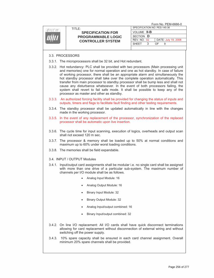
3.3.1. The microprocessors shall be 32 bit, and Hot redundant.
3.3.2. Hot redundancy: PLC shall be provided with two processors (Main processing unit and memories) one for normal operation and one as hot standby. In case of failure of working processor, there shall be an appropriate alarm and simultaneously the hot standby processor shall take over the complete operation automatically. This transfer from main processor to standby processor shall be bump less and shall not cause any disturbance whatsoever. In the event of both processors failing, the system shall revert to fail safe mode. It shall be possible to keep any of the processor as master and other as standby.
3.3.3. An authorized forcing facility shall be provided for changing the status of inputs and outputs, timers and flags to facilitate fault finding and other testing requirements.
3.3.4. The standby processor shall be updated automatically in line with the changes made in the working processor.
3.3.5. In the event of any replacement of the processor, synchronization of the replaced processor shall be automatic upon live insertion.
3.3.6. The cycle time for input scanning, execution of logics, overheads and output scan shall not exceed 120 m sec.
3.3.7. The processor & memory shall be loaded up to 50% at normal conditions and maximum up to 60% under worst loading conditions.
3.3.8. The memories shall be field expandable.
3.4. INPUT / OUTPUT Modules
3.4.1. Input/output card assignments shall be modular i.e. no single card shall be assigned with more than one drive of a particular sub-system. The maximum number of channels per I/O module shall be as follows.
� Analog Input Module: 16
� Analog Output Module: 16
� Binary Input Module: 32
� Binary Output Module: 32
� Analog Input/output combined: 16
� Binary Input/output combined: 32
3.4.2. On line I/O replacement: All I/O cards shall have quick disconnect terminations allowing for card replacement without disconnection of external wiring and without switching off the power supply.
3.4.3. 10% spare capacity shall be ensured in each card channel assignment. Overall minimum 20% spare channels shall be provided.
Page 256 of 277

Form No. PEM-6666-0 SPECIFICATION NO. PES-145-36
VOLUME II-BSECTION DREV. NO. 02 DATE: July 19, 2008SHEET 4 OF 9
TITLE: SPECIFICATION FOR
PROGRAMMABLE LOGIC CONTROLLER SYSTEM
3.4.4. Output command to MCC/Switchgear shall be through coupling relays, whose mounting location shall be as per “Data sheet A & B for PLC System”. In case coupling relays are located in PLC Panel, the same shall be in PLC vendor’s scope of supply.
3.4.5. Status feedback from MCC shall be in the form of potential free contact.
3.5. DATA BUS/ I/O BUS
3.5.1. The Data bus connecting PLC and HMI work stations shall be TCP/IP on Ethernet.
3.5.2. The Data bus and I/O bus communication medium shall be twisted pair shield copper conductor for indoor locations and those areas not subjected to induced signals. Repeaters/signal amplifiers shall not be used. Copper conductor cable used shall be Category-5 or better. The communication medium shall be Fibre optic cable in the event any portion of communication cable run is in outdoor or where distances are beyond 500 meters.
3.6. OPERATOR WORK STATION (OWS)
3.6.1. The OWS and Keyboard shall be desktop mounted and shall be used for controlling, monitoring and programming function.
3.6.2. Colour CRT(s) with keyboard and mouse shall be as per Data Sheet-A&B. CRT shall have graphic display facility.
3.6.3. The OWS shall be with Windows based operating system having necessary Engineering/Configuring software.
3.7. PRINTER
Printers shall be provided as per Data Sheet-A&B.
Page 257 of 277
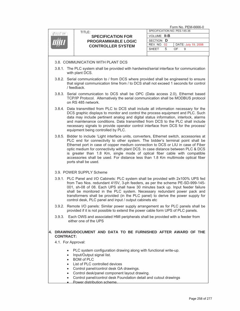
Form No. PEM-6666-0 SPECIFICATION NO. PES-145-36
VOLUME II-BSECTION DREV. NO. 02 DATE: July 19, 2008SHEET 5 OF 9
TITLE: SPECIFICATION FOR
PROGRAMMABLE LOGIC CONTROLLER SYSTEM
3.8. COMMUNICATION WITH PLANT DCS
3.8.1. The PLC system shall be provided with hardwired/serial interface for communication with plant DCS.
3.8.2. Serial communication to / from DCS where provided shall be engineered to ensure that signal communication time from / to DCS shall not exceed 1 seconds for control / feedback.
3.8.3. Serial communication to DCS shall be OPC (Data access 2.0), Ethernet based TCP/IP Protocol. Alternatively the serial communication shall be MODBUS protocol on RS 485 network.
3.8.4. Data transmitted from PLC to DCS shall include all information necessary for the DCS graphic displays to monitor and control the process equipment and PLC. Such data may include pertinent analog and digital status information, interlock, alarms and maintenance conditions. Data transmitted from DCS to the PLC shall include necessary signals to provide operator control interface from DCS for the process/ equipment being controlled by PLC.
3.8.5. Bidder to include ‘Light interface units, converters, Ethernet switch, accessories at PLC end for connectivity to other system. The bidder’s terminal point shall be Ethernet port in case of copper medium connection to DCS or LIU in case of Fiber optic medium for connectivity with plant DCS. In case distance between PLC & DCS is greater than 1.8 Km, single mode of optical fiber cable with compatible accessories shall be used. For distance less than 1.8 Km multimode optical fiber ports shall be used.
3.9. POWER SUPPLY Scheme
3.9.1. PLC Panel and I/O Cabinets: PLC system shall be provided with 2x100% UPS fed from Two Nos. redundant 415V, 3-ph feeders, as per the scheme PE-SD-999-145-001, sh-08 of 08. Each UPS shall have 30 minutes back up. Input feeder failure shall be monitored in the PLC system. Necessary redundant power pack and transformers shall be provided (in the PLC panel) to derive the power supply for control desk, PLC panel and input / output cabinets etc
3.9.2. Remote I/O panels: Similar power supply arrangement as for PLC panels shall be provided if it is not possible to extend the power cable form UPS of PLC panels.
3.9.3. Each OWS and associated HMI peripherals shall be provided with a feeder from either one of the UPS
4. DRAWING/DOCUMENT AND DATA TO BE FURNISHED AFTER AWARD OF THE CONTRACT: 4.1. For Approval:
� PLC system configuration drawing along with functional write-up. � Input/Output signal list. � BOM of PLC � List of PLC controlled devices � Control panel/control desk GA drawings. � Control desk/panel component layout drawing. � Control panel/control desk Foundation detail and cutout drawings � Power distribution scheme.
Page 258 of 277

Form No. PEM-6666-0 SPECIFICATION NO. PES-145-36
VOLUME II-BSECTION DREV. NO. 02 DATE: July 19, 2008SHEET 6 OF 9
TITLE: SPECIFICATION FOR
PROGRAMMABLE LOGIC CONTROLLER SYSTEM
� Block logic diagrams. � Annunciation list. � PLC control room layout drawing. � List of soft signal exchange with Plant DCS. � List of mandatory spares � Quality plan � Data Sheet-C � CRT display � Power supply scheme for PLC system, HMI & peripherals, Remote I/O etc.
4.2. For Information:
� Cable schedule and cable interconnection drawing( in BHEL approved format) � Between Field and PLC � Between Field and MCC � Between MCC and PLC
� Electronic earthing requirements. � Panel Heat dissipation data � Product/component catalogues. � Operation & Maintenance Manual on CDs. � Softcopy of Final/As-built drawings on CDs. � Calculation for Processor, Memory & Data bus loading
The above list is the minimum requirements. Additional documents/calculations required shall be finalized during contract stage.
5. DRAWINGS AND DOCUMENTS TO BE SUBMITTED ALONG WITH THE BID
� Proposed PLC system configuration drawing with write-up � Product catalogues and specifications for PLC as well as HMI application. � Proposed power supply schemes for PLC system, peripherals, and Remote I/O
panels.
6. TESTING AND INSPECTION6.1. The bidder shall adopt suitable quality assurance program to ensure that the
equipments offered will meet the specification requirements in full.
6.2. BHEL’s standard Quality Plan for PLC is enclosed with the specification. The bidder shall furnish his acceptance to BHEL’s QP and submit the signed and stamped copy of QP along with the offer.
6.3. The complete PLC system, including all instrument and devices shall be subjected to standard factory tests (i.e. Type Tests and Routine Tests) as per relevant IS, NEMA, IEEE, IEC.
6.4. Factory Acceptance Test-FAT (Functional Tests) shall be performed prior to shipment and Owner/Purchaser shall be notified 15 days before the schedules dates of the test.
6.5. The certificates for following type tests, as per IEC Standard, shall be submitted: -
� Surge protection test as per IEC-225-4 � Dry heat test as per IEC-68-2-2 � Damp Heat test as per IEC-68-2-3
Page 259 of 277

Form No. PEM-6666-0 SPECIFICATION NO. PES-145-36
VOLUME II-BSECTION DREV. NO. 02 DATE: July 19, 2008SHEET 7 OF 9
TITLE: SPECIFICATION FOR
PROGRAMMABLE LOGIC CONTROLLER SYSTEM
� Vibration Heat test as per IEC-68-2-6 � Electrostatic discharge test as per IEC-801-2 or equivalent � Radio frequency Immunity test as per IEC-801-6 or equivalent � Electromagnetic Immunity test as per IEC-801-3 or equivalent
7. SPARES AND CONSUMABLES
7.1. Commissioning Spares and consumables
The bidder shall supply all commissioning spares and consumables ‘as required’ during Start-up, as part of the main equipment supply.
7.2. Mandatory Spares
The bidder shall offer alongwith main offer, the Mandatory Spares as specified elsewhere in the specification. The Mandatory Spares offered shall be of the same make and type as the main equipment.
7.3. Recommended Spares
The bidder shall furnish a list of Recommended Spares indicating the normal service expectancy period and frequency of replacement; quantities recommended for 3 years operation alongwith unit rate against each item to enable BHEL/BHEL’s Customer to place a separate order later, if required.
7.4. Special Tools & Tackles
The bidder shall supply all Special Tools & Tackles ‘as required’ during Start-up and further maintenance of the system, as part of the main equipment supply.
7.5. Spares, Service support
Bidder shall provide availability of spares and service support for minimum 10 years after guarantee period.
8. MARKING AND PACKING
8.1. Marking:
A stainless steel name-plate shall be permanently fixed on each equipment giving its Tag/serial Number and salient technical specification.
8.2. Packing:
All equipment/materials shall be suitably packed and protected for the entire period of dispatch, storage and erection against impact, abrasion, corrosion, incidental damage due to vermin, sunlight, high temperature, rain, moisture, humidity, dust, sea-water spray (where applicable) as well as rough handling and delays in transit and storage in open.
9. PERFORMANCE AND GUARANTEE
Page 260 of 277

Form No. PEM-6666-0 SPECIFICATION NO. PES-145-36
VOLUME II-BSECTION DREV. NO. 02 DATE: July 19, 2008SHEET 8 OF 9
TITLE: SPECIFICATION FOR
PROGRAMMABLE LOGIC CONTROLLER SYSTEM
The PLC system shall be guaranteed to meet the performance requirement as specified and also for trouble-free continuous operation for 12 months from the date of commissioning or 18 months from the date of delivery at site whichever is later unless specified otherwise in Vol-IIB Section - B or Section - C.
10. APPLICABLE DATA SHEET FORMS
This document shall be read with the following data sheet forms :
- Data Sheet A & B for PLC system - PE-DC-999-145-I036-1
- Data Sheet C for PLC system - PE-DC-999-145-I036-2
11. Bidder shall provide at least 20% wired spare capacity of I/O modules over andabove system requirement..12. Bidder shall include 10% or 1 No. (whichever is higher) each type of module,which shall include controller card, communication card, I/O card, Power supply card/unit, relays, push button, lamps etc.
Page 261 of 277
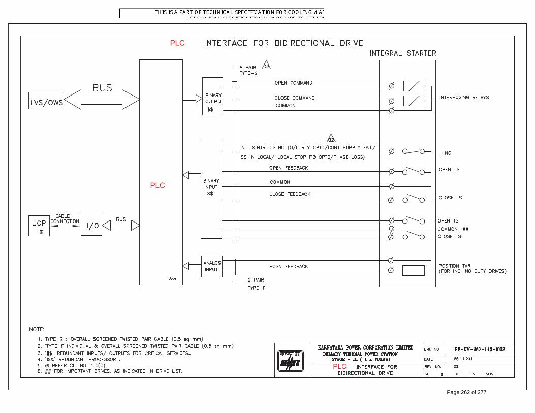
PLC
PLC
PLC
Page 262 of 277

PLC
PLC
PLC
Page 263 of 277

PLC
PLC
PLC
Page 264 of 277

60 MIN 60 MIN
UPSUPS
SINGLE LINE DIAGRAM OF UPS
Page 265 of 277

SN Parameters Options available Remarks if any
1 Model No.& Make of Device
2 Communications Link Options
3 Protocol Mode (Device is a)
4 Protocol
5 Master
6 Dist.bet.maxDNA System & Device*
1 Interface Type
2 Wiring at Device end
3 Transmission Channel
4 Baud Rates (bps)
5 Databits
6 Stopbits
7 Parity
8 H/w & Software Handshake
9 Response Timeout time (Sec)
10 Data Formats Supported
11 Transmission mode
1 Primary Function*
2 Analog Points to read
3 Analog Points to write
4 Digital Points to read
5 Digital Points to write
6 Memory / Flag Points to read
7 Memory / Flag Points to write
1 Cable type
2 Cable Details Enclosed
3 Any specific Converter required
1 Manufacturer's Documents*
C1 What is the primary purpose of the communications link?
E1 Reqd. Contents : This document must provide an overview of the device including its intended
use(a general technical,communication & electrical details)
*Notes:
A6 To identify converter requirement and cable length.
C The sr.no.1 to 7 are reqd.to be furnished for interface impl. :such as Tagname,Description,point type,
modbus(Register) address,EU,range & device (dlave) address
C Application Specific : *
D Hardware Specific :
E Device Documents :
Cheklist for Serial Communication between maxDNA Systems and Foreign Device :BHEL
A Device Specific :
B Electrical Spcific :
Multidrop Peer to Peer
Master Slave
N/w topology attached
Master/Slave
RTU ASCII Other -------------------
System maxDNA Other -------------------
-------------- Feet --------------- Meters
RS232 RS422 RS485
Half Duplex Full Duplex
1200 2400 4800
8 7
1 2
None Odd
2 Wire 4 Wire
9600 19200
Even
-------------- Configurable timeout
Boolean Real Char
Asynchronous Synchronous
Yes No
Sn.Int UnSn.Int
Data Acquisition Data Acquisition & Control
Details attached Details not attached
Download parameter sets
Details attached Details not attached
Details attached Details not attached
Details attached Details not attached
Details attached Details not attached
Details attached Details not attached--------Nos.
--------Nos.
--------Nos.
--------Nos.
--------Nos.
--------Nos.
Yes No
Yes No
Boolean cable Twisted pair cable
Details enclosed
Tech., Spec. Operating Manual
Page 266 of 277

Serial No Tag name Tag Description Modbus address Point Type ENGG. UNIT Range Function Code
Note:1234567
Function code is Modbus function code used to update data from slave to master Ex Function Code for Read Input Register etcKindly Indicate Start and end register address for each function type and each block of data
Format for exchange of signals with DDCMIS
Tag Name and Descriptions are of that of Slave devicesModbus Address is register address in Slave DeviceEngg unit is unit of measurement Ex Pressure - bar, Temp Deg C etcPoint type is Analog or packed binaryRange applicable for analog value and is instrument range
Page 267 of 277