best practices: electronics cooling - mdx · pdf file•thermal (including radiation)...
TRANSCRIPT
Best Practices: Electronics Cooling
Ruben Bons - CD-adapco
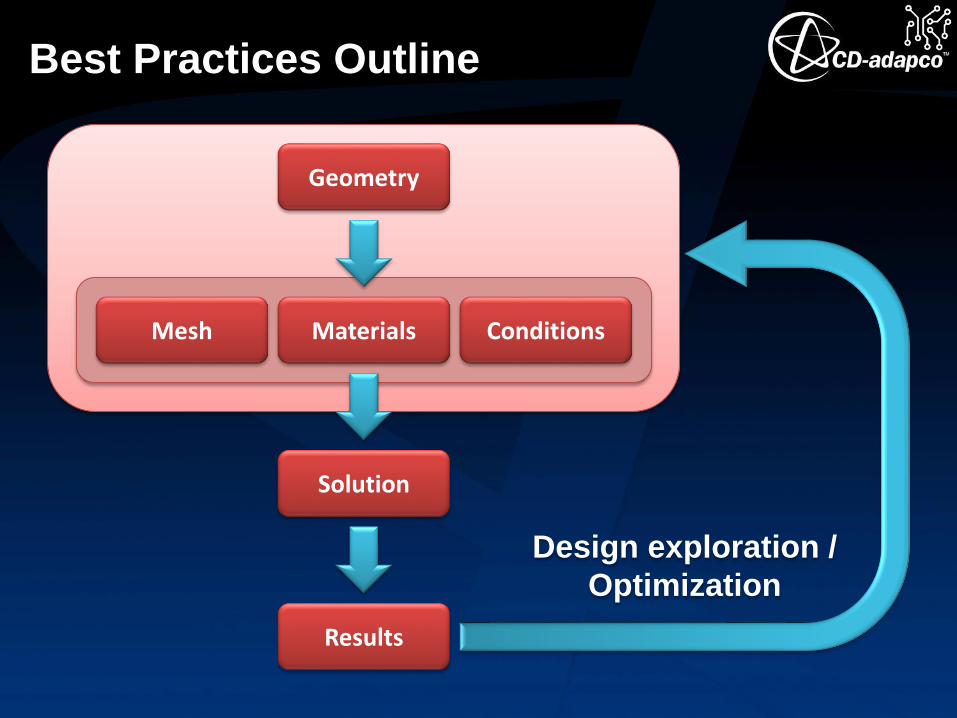
Best Practices Outline
Geometry
MaterialsMesh Conditions
Solution
Results
Design exploration /
Optimization

Best Practices Outline
Geometry• Solids
• Simplification
• Preparation
• Air
• Forced convection
• Natural convection
Mesh• Trimmed / Polyhedral
• Conformal / Non-conformal
• Thin solids
• Prism layers in air
• Mesh operations
Materials• Solids
• Air (fluid)
• “Devices”
• Chips
• PCBs
• Porous media, perf plates
• Heat pipes
• Thermoelectric devices
Conditions• Physics: Flow & heat transfer
• Environment
• Inlet(s)
• Outlet(s)
• Thermal (including radiation)
• Heat sources
• Fans & blowers
Solution• Physics models
• Reference values / Initial conditions
• Segregated or Coupled
• Under-relaxation
• Convergence
Results• Temperature
• Velocity
• Field functions

Geometry
Geometry Mesh Materials
ConditionsSolutionResults
Geometry
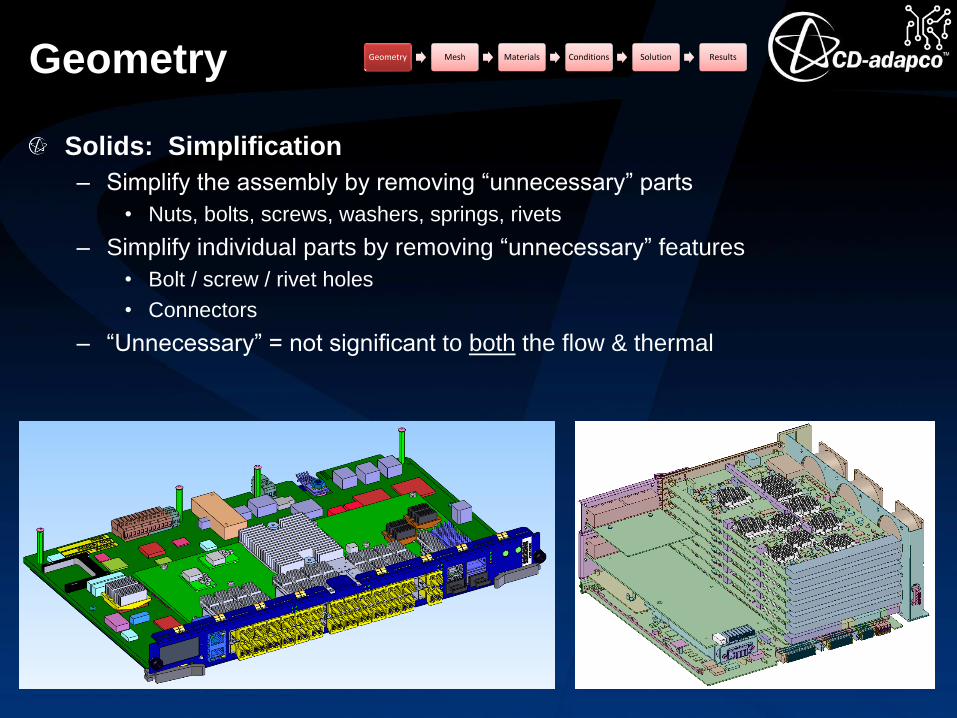
Solids: Simplification
– Simplify the assembly by removing “unnecessary” parts
• Nuts, bolts, screws, washers, springs, rivets
– Simplify individual parts by removing “unnecessary” features
• Bolt / screw / rivet holes
• Connectors
– “Unnecessary” = not significant to both the flow & thermal
Geometry Mesh Materials Conditions Solution Results

Geometry Geometry Mesh Materials Conditions Solution Results
Geometry
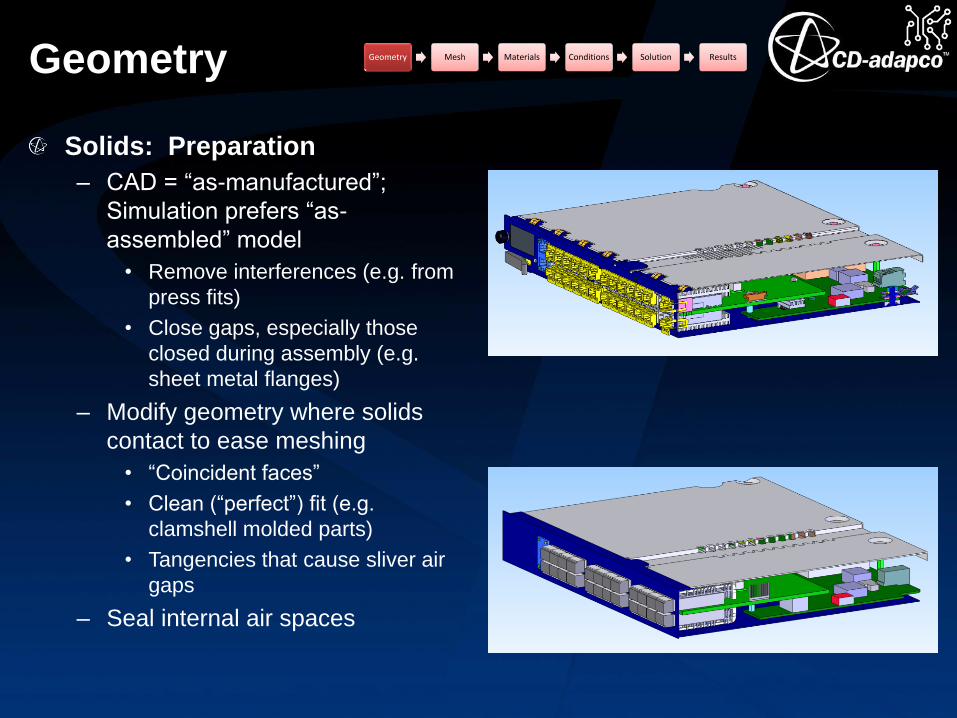
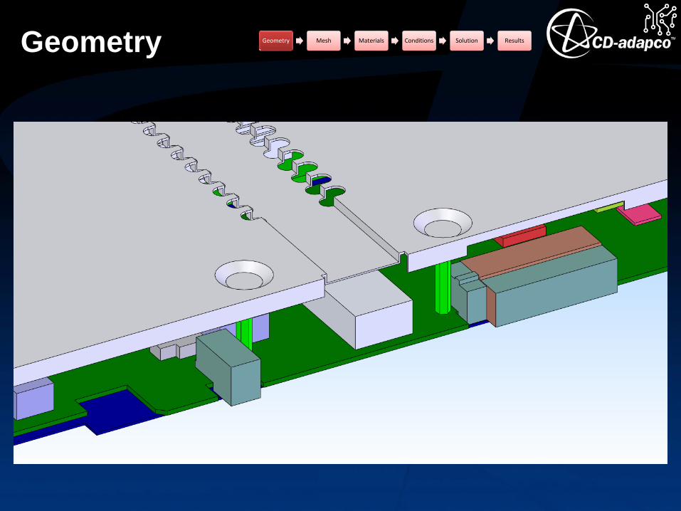
Solids: Preparation
– CAD = “as-manufactured”;
Simulation prefers “as-
assembled” model
• Remove interferences (e.g. from
press fits)
• Close gaps, especially those
closed during assembly (e.g.
sheet metal flanges)
– Modify geometry where solids
contact to ease meshing
• “Coincident faces”
• Clean (“perfect”) fit (e.g.
clamshell molded parts)
• Tangencies that cause sliver air
gaps
– Seal internal air spaces
Geometry Mesh Materials Conditions Solution Results

Geometry Geometry Mesh Materials Conditions Solution Results
Geometry Geometry Mesh Materials Conditions Solution Results
Geometry
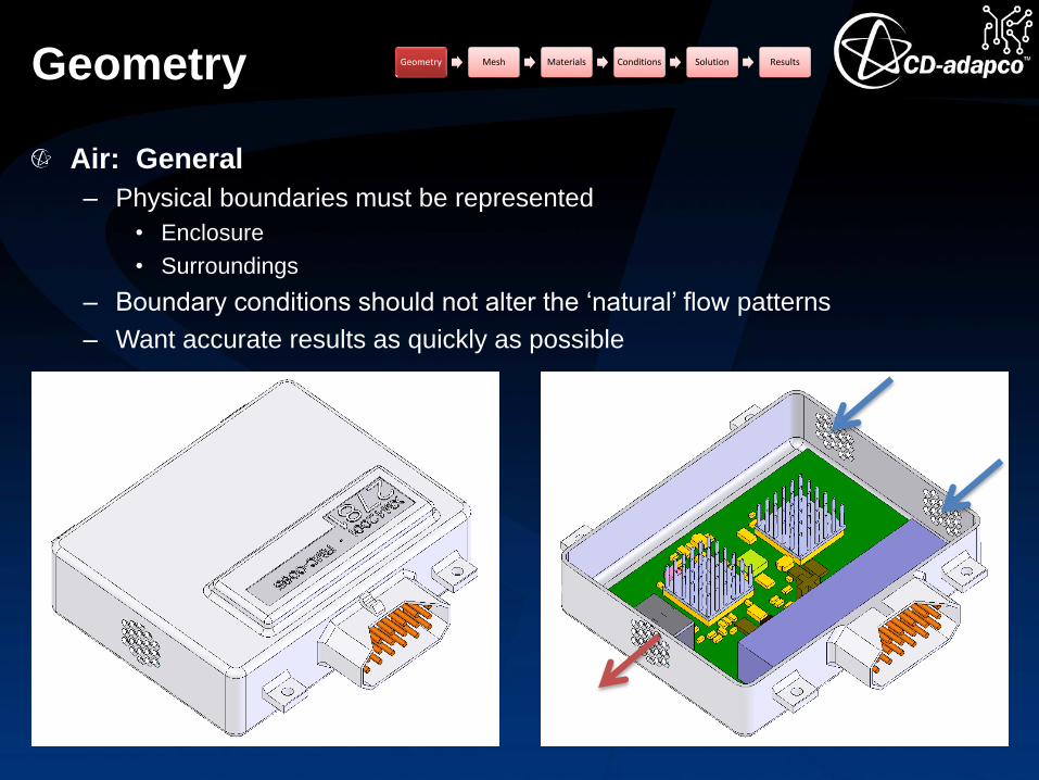
Air: General
– Physical boundaries must be represented
• Enclosure
• Surroundings
– Boundary conditions should not alter the ‘natural’ flow patterns
– Want accurate results as quickly as possible
Geometry Mesh Materials Conditions Solution Results
Geometry
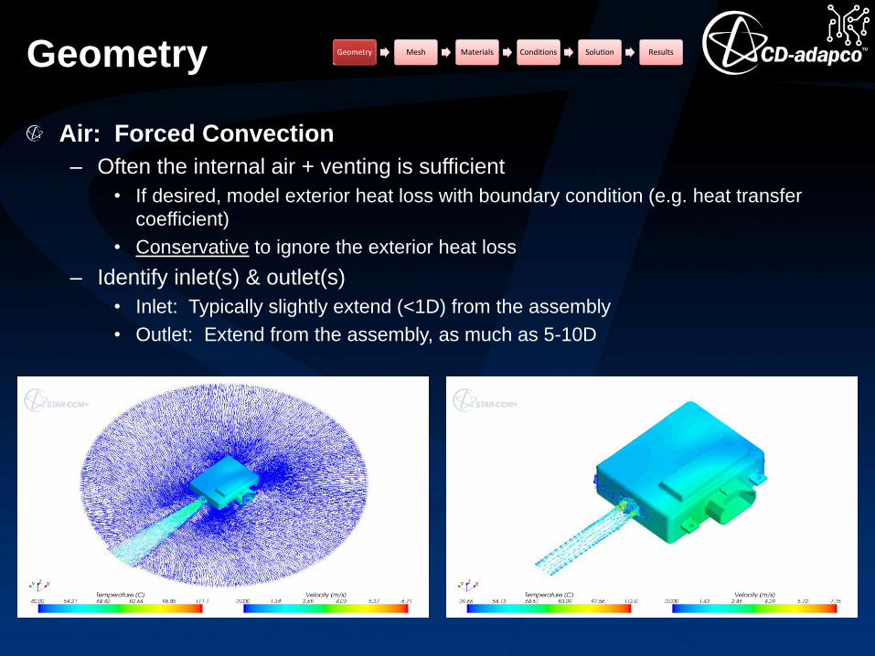
Air: Forced Convection
– Often the internal air + venting is sufficient
• If desired, model exterior heat loss with boundary condition (e.g. heat transfer
coefficient)
• Conservative to ignore the exterior heat loss
– Identify inlet(s) & outlet(s)
• Inlet: Typically slightly extend (<1D) from the assembly
• Outlet: Extend from the assembly, as much as 5-10D
Geometry Mesh Materials Conditions Solution Results

Geometry
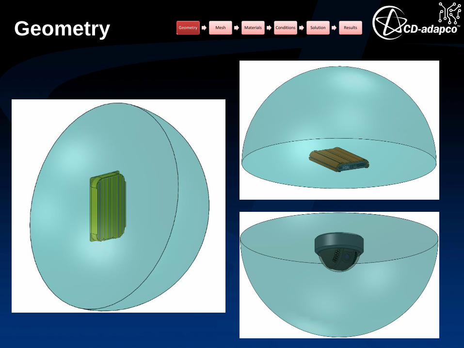
Air: Natural Convection
– To simulate air flow & heat transfer on the exterior, model the surrounding air
(use a sphere as the baseline, diameter ~3-5X the bounding box diagonal).
– To model the heat transfer on the exterior, add boundary conditions (e.g. heat
transfer coefficient)
Geometry Mesh Materials Conditions Solution Results
Geometry Geometry Mesh Materials Conditions Solution Results

Mesh
Geometry Mesh Materials
ConditionsSolutionResults

Mesh
Cell topology
– Polyhedral
• Conformal
• Non-conformal
– Trimmed hexahedral
• Non-conformal
Approaches
– Parts-based
– Regions-based
Specialty options
– Prism-layer mesher
– Thin mesher
– Extruded mesher
Basic setting: Mesh sizing
Conformal vs Non-conformal
– Conformal possible only with
polyhedral cells
– Non-conformal an option with
polyhedral, trimmed hexahedral
– Accuracy
• Fully conformal is best (no
interpolation at interfaces)
• Non-conformal with similar
surface mesh sizes: Tests show
very small (<0.5%) difference
than fully-conformal results.
• Non-conformal with disparate
mesh sizes: Accuracy degrades
as surface size variance
increases
– Meshing speed
• Non-conformal is fastest
• Serial & parallel option for both
• Concurrent option for non-conf
Geometry Mesh Materials Conditions Solution Results
Mesh
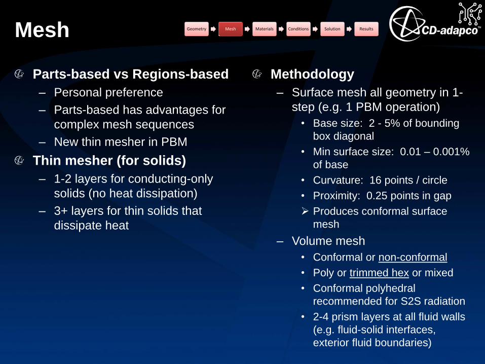
Parts-based vs Regions-based
– Personal preference
– Parts-based has advantages for
complex mesh sequences
– New thin mesher in PBM
Thin mesher (for solids)
– 1-2 layers for conducting-only
solids (no heat dissipation)
– 3+ layers for thin solids that
dissipate heat
Methodology
– Surface mesh all geometry in 1-
step (e.g. 1 PBM operation)
• Base size: 2 - 5% of bounding
box diagonal
• Min surface size: 0.01 – 0.001%
of base
• Curvature: 16 points / circle
• Proximity: 0.25 points in gap
Produces conformal surface
mesh
– Volume mesh
• Conformal or non-conformal
• Poly or trimmed hex or mixed
• Conformal polyhedral
recommended for S2S radiation
• 2-4 prism layers at all fluid walls
(e.g. fluid-solid interfaces,
exterior fluid boundaries)
Geometry Mesh Materials Conditions Solution Results

Mesh Geometry Mesh Materials Conditions Solution Results
Conformal solid-solid interface
Fluid prism layers
Non-conformal fluid-solid interface

Mesh Geometry Mesh Materials Conditions Solution Results
Materials
Geometry Mesh Materials
ConditionsSolutionResults
Materials
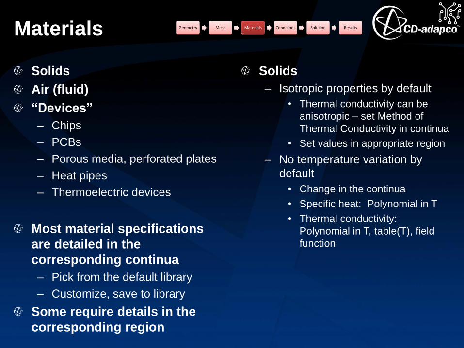
Solids
Air (fluid)
“Devices”
– Chips
– PCBs
– Porous media, perforated plates
– Heat pipes
– Thermoelectric devices
Most material specifications
are detailed in the
corresponding continua
– Pick from the default library
– Customize, save to library
Some require details in the
corresponding region
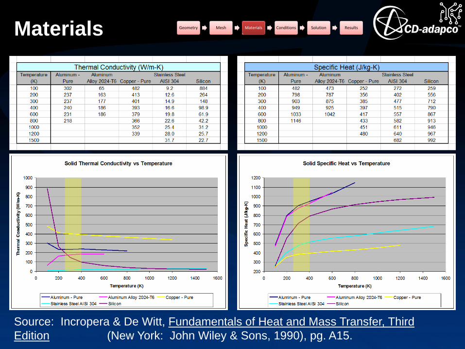
Solids
– Isotropic properties by default
• Thermal conductivity can be
anisotropic – set Method of
Thermal Conductivity in continua
• Set values in appropriate region
– No temperature variation by
default
• Change in the continua
• Specific heat: Polynomial in T
• Thermal conductivity:
Polynomial in T, table(T), field
function
Geometry Mesh Materials Conditions Solution Results
Materials Geometry Mesh Materials Conditions Solution Results
Source: Incropera & De Witt, Fundamentals of Heat and Mass Transfer, Third
Edition (New York: John Wiley & Sons, 1990), pg. A15.

Materials
Fluid
– Most commonly air
– Liquid cooling with water,
ethylene-glycol solution, etc.
Properties & appropriate
physics specified in the
continua
– Properties
• Density
• Viscosity
• Specific heat
• Thermal conductivity
– Physics
• Laminar or turbulent
• Turbulence model
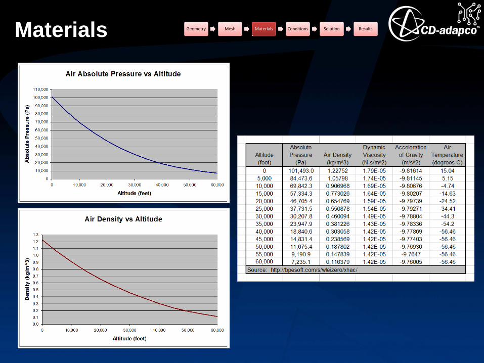
Properties: Air
– Density
• For buoyancy (natural
convection), density must vary
with temperature (+ gravity)
• Ambient pressure strongly
affects air density (e.g. at
altitude)
– Viscosity can significantly vary
with temperature
Properties: Water
– Density
• Variation with temperature
important only with natural
convection (rare cases)
• Little variation with pressure
– Viscosity variation with
temperature can be significant
Geometry Mesh Materials Conditions Solution Results

Materials Geometry Mesh Materials Conditions Solution Results
Common
temperature range
in electronics
Materials Geometry Mesh Materials Conditions Solution Results

Materials Geometry Mesh Materials Conditions Solution Results

Materials
Laminar or Turbulent (for air)
– Forced convection: Generally
turbulent
• Internal: Transition @ Re ~
2500 – 10,000
• External: Transition @ Re ~
500,000
– Natural convection: Generally
laminar
• Turbulent if Rah > 109 (vertical
flat plate)
• Assume
– Tw = 85 oC
– T∞ = 50 oC
• Properties @ 70 oC
• hcritical = 0.83 m
Turbulence model
– Many options in STAR-CCM+,
consult the help for details
• k-ε
• k-ω
• Reynolds stress
• Spalart-Allmaras
• DES
• LES
– Realizable k-ε with two-layer all-
y+ wall treatment seems to work
well for a wide range of models
• Forced convection
• Natural convection
– Compared a laminar run with a
k-ε run
– Essentially identical flow &
thermal results
Geometry Mesh Materials Conditions Solution Results
𝑹𝒂𝒉 =𝒈𝜷 𝑻𝒘 − 𝑻∞ 𝒉𝟑
𝝊𝜶

Materials
Device: Chips
– Solid (isotropic) material
– 2-resistor
• High conductivity solid (e.g. Cu)
• Separate boundaries (in the
region) for top & bottom surfaces
• Assign resistivity to interfaces to achieve ϴjb & ϴjc.
• Resistivity ρ = t / k = Rt*Acontact.
Device: PCBs
– Equivalent thermal properties
• Orthotropic equivalent properties
computed from geometric details
(easiest in a spreadsheet)
• Commonly kin-plane ~ 10 W/m-K ~
20*kthrough-thickness.
– Detailed trace modeling
• Computationally costly
• 2D or 3D traces
Geometry Mesh Materials Conditions Solution Results

Materials
Device: Porous media
– Fluid region, Type = Porous
Region
– Set Inertial &/or Viscous
resistance values under Region
Physics Values
• Viscous: ΔP α V (e.g. fibrous
filter)
• Inertial: ΔP α V2 (e.g. perf plate)
Device: Heat pipes
– Rarely are the full physics
(evaporation, condensation,
surface tension, etc.) modeled.
– Typically 3-part assembly
• Pipe wall (k = material
conductivity)
• Wick (k = 30-40 W/m-K)
• Vapor space (k > 10,000 W/m-K)
Geometry Mesh Materials Conditions Solution Results
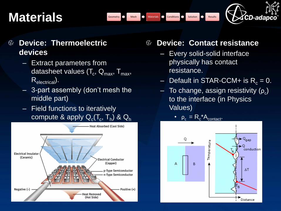
Materials
Device: Thermoelectric
devices
– Extract parameters from
datasheet values (Tc, Qmax, Tmax,
Relectrical).
– 3-part assembly (don’t mesh the
middle part)
– Field functions to iteratively
compute & apply Qc(Tc, Th) & Qh
(Tc, Th).
Device: Contact resistance
– Every solid-solid interface
physically has contact
resistance.
– Default in STAR-CCM+ is Rc = 0.
– To change, assign resistivity (ρc)
to the interface (in Physics
Values)
• ρc = Rc*Acontact.
Geometry Mesh Materials Conditions Solution Results

Conditions
Geometry Mesh Materials
ConditionsSolutionResults
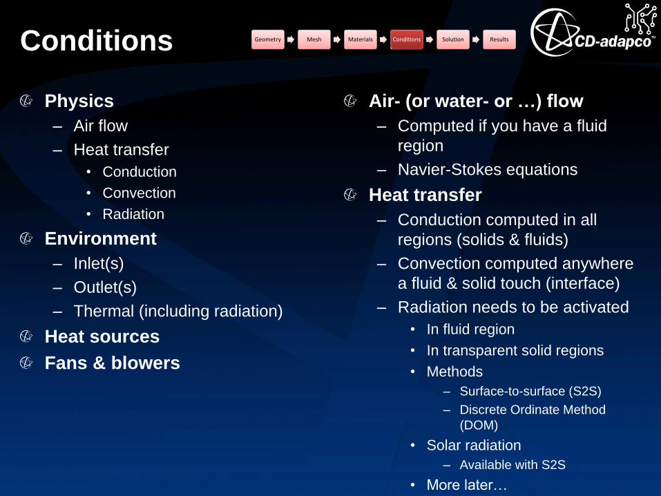
Conditions
Physics
– Air flow
– Heat transfer
• Conduction
• Convection
• Radiation
Environment
– Inlet(s)
– Outlet(s)
– Thermal (including radiation)
Heat sources
Fans & blowers
Air- (or water- or …) flow
– Computed if you have a fluid
region
– Navier-Stokes equations
Heat transfer
– Conduction computed in all
regions (solids & fluids)
– Convection computed anywhere
a fluid & solid touch (interface)
– Radiation needs to be activated
• In fluid region
• In transparent solid regions
• Methods
– Surface-to-surface (S2S)
– Discrete Ordinate Method
(DOM)
• Solar radiation
– Available with S2S
• More later…
Geometry Mesh Materials Conditions Solution Results
Conditions
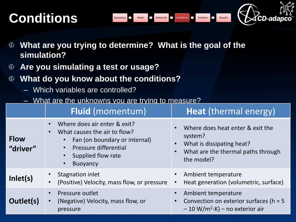
What are you trying to determine? What is the goal of the
simulation?
Are you simulating a test or usage?
What do you know about the conditions?
– Which variables are controlled?
– What are the unknowns you are trying to measure?
Fluid (momentum) Heat (thermal energy)
Flow “driver”
• Where does air enter & exit?• What causes the air to flow?
• Fan (on boundary or internal)• Pressure differential• Supplied flow rate• Buoyancy
• Where does heat enter & exit the system?
• What is dissipating heat?• What are the thermal paths through
the model?
Inlet(s)• Stagnation inlet• (Positive) Velocity, mass flow, or pressure
• Ambient temperature• Heat generation (volumetric, surface)
Outlet(s)• Pressure outlet• (Negative) Velocity, mass flow, or
pressure
• Ambient temperature• Convection on exterior surfaces (h = 5
– 10 W/m2-K) – no exterior air
Geometry Mesh Materials Conditions Solution Results
Conditions
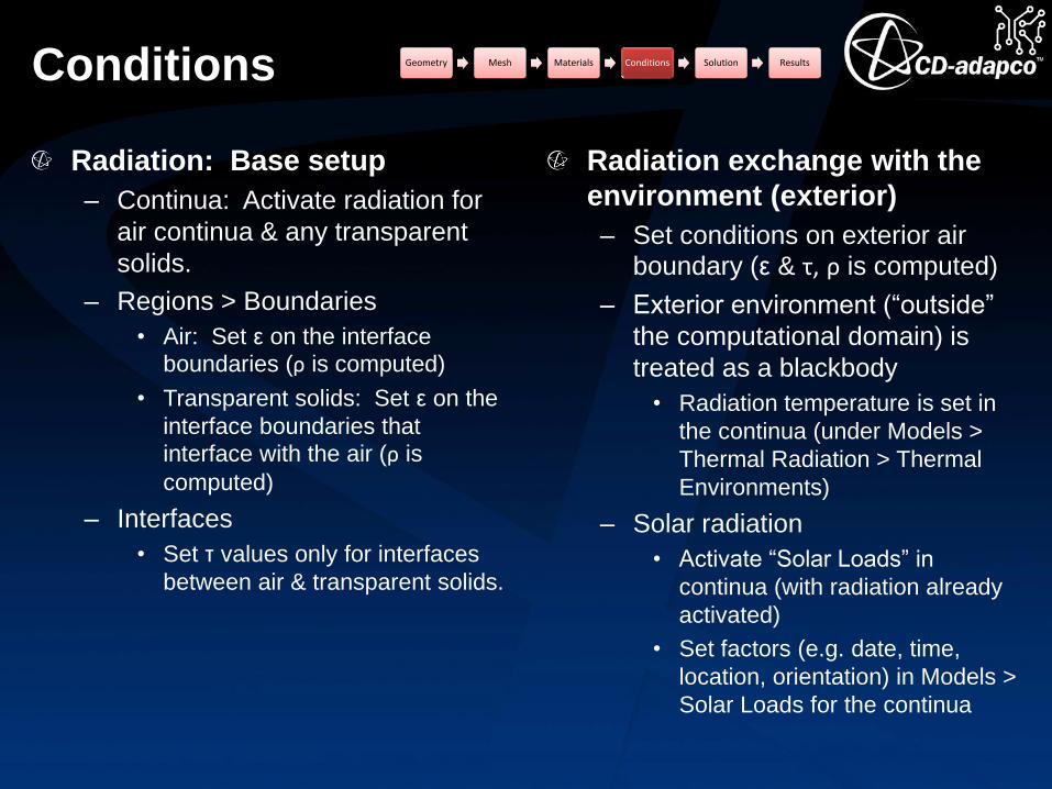
Radiation: Base setup
– Continua: Activate radiation for
air continua & any transparent
solids.
– Regions > Boundaries
• Air: Set ε on the interface boundaries (ρ is computed)
• Transparent solids: Set ε on the
interface boundaries that interface with the air (ρ is
computed)
– Interfaces
• Set τ values only for interfaces
between air & transparent solids.
Radiation exchange with the
environment (exterior)
– Set conditions on exterior air boundary (ε & τ, ρ is computed)
– Exterior environment (“outside”
the computational domain) is
treated as a blackbody
• Radiation temperature is set in
the continua (under Models >
Thermal Radiation > Thermal
Environments)
– Solar radiation
• Activate “Solar Loads” in
continua (with radiation already
activated)
• Set factors (e.g. date, time,
location, orientation) in Models >
Solar Loads for the continua
Geometry Mesh Materials Conditions Solution Results
Conditions Geometry Mesh Materials Conditions Solution Results
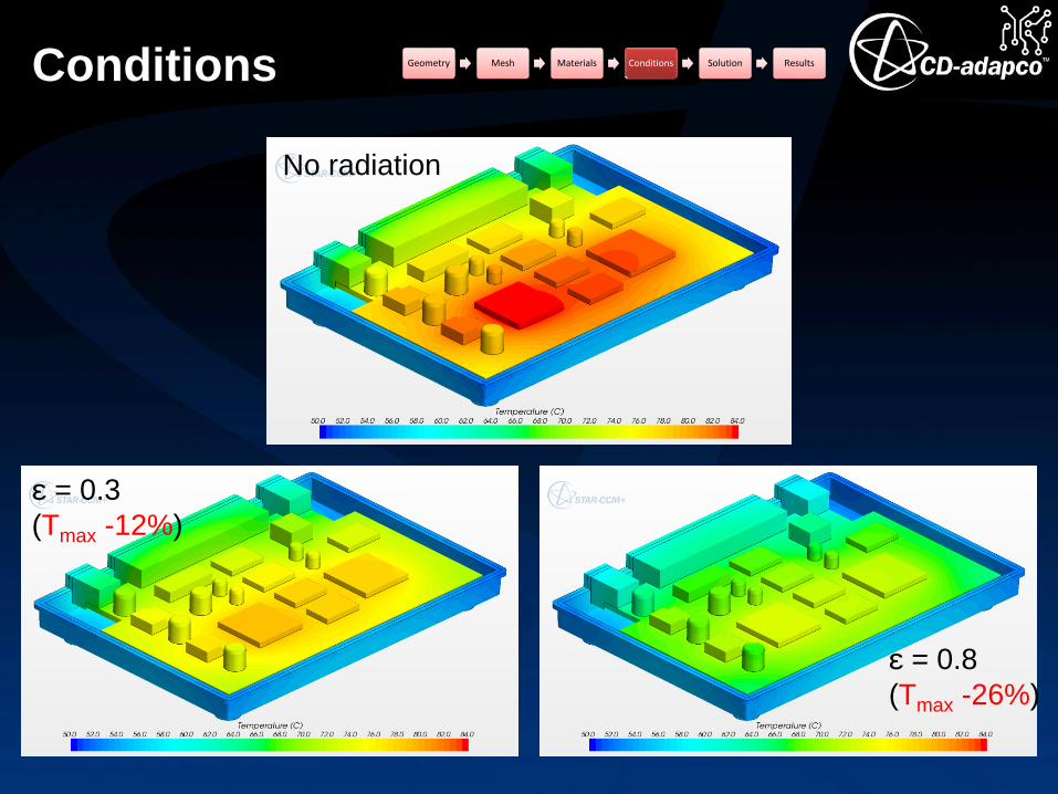
No radiation
ε = 0.3
(Tmax -12%)
ε = 0.8
(Tmax -26%)

Conditions
How do we know the heat dissipation to specify for a component?
Apply the heat dissipation to the appropriate region
– Activate the Energy Source Option in Physics Conditions
– Assign the Heat Source in Physics Values
– Value assigned applies to the entire region (even if it consists of multiple
parts).
Geometry Mesh Materials Conditions Solution Results
Electrical
power supplied
Component
(e.g. IC, IGBT,
MOSFET,
LED,…)
Electrical power
delivered
RF energy,
visible light
• “Wall power”?
• Max power (power
budget)?
• Measured power?
• Duty-cycled?
• What is the efficiency?
Heat
Conditions Geometry Mesh Materials Conditions Solution Results
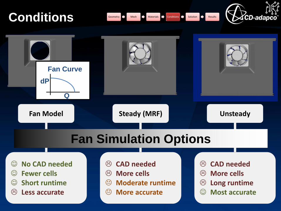
Fan Model
No CAD needed Fewer cells Short runtime Less accurate
Steady (MRF)
CAD needed More cells Moderate runtime More accurate
Unsteady
CAD needed More cells Long runtime Most accurate
Fan Curve
dP
Q
Fan Simulation Options

Conditions
Fan models in STAR-CCM+
(immersed fans)
– Volume momentum source
– Interface momentum source
Recommendation: Interface
– Geometry with faces where the
interface is desired.
– Set interface Type = Fan
Interface.
– Input the desired fan curve
Boundary fans (inlet and/or
outlet) also available
STAR-CCM+ iterates to find the
flow rate / pressure drop
combination at the intersection
of the fan curve & the system
resistance curve.
Blowers are modeled as a
special interface type
– Centrifugal fan
– Impeller fan
Geometry Mesh Materials Conditions Solution Results

Solution
Geometry Mesh Materials
ConditionsSolutionResults

Solution
Air continuum
– Models
• Segregated Fluid Temperature
• Ideal gas or Boussinesq
recommended for natural
convection
• Gravity (activated)
– Reference values
• Gravity (vector direction) for
natural convection
• Reference altitude
• Reference density = density at
Tambient (based on ideal gas)
– Initial conditions
• Pressure = 0 (gage)
• Static temperature = Tambient
• Velocity = 0
Continua settings
– Physics models
– Reference values
– Initial conditions
Solution settings
– Under-relaxation
– Convergence
Solids continua
– Models
• Segregated Solid Energy
– Reference values
• None
– Initial conditions
• Static temperature = Tambient
Geometry Mesh Materials Conditions Solution Results
Solution Geometry Mesh Materials Conditions Solution Results
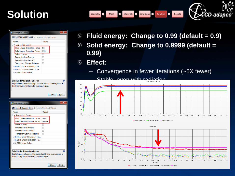
Fluid energy: Change to 0.99 (default = 0.9)
Solid energy: Change to 0.9999 (default =
0.99)
Effect:
– Convergence in fewer iterations (~5X fewer)
– Stable, even with radiation
Results
Geometry Mesh Materials
ConditionsSolutionResults

Results Geometry Mesh Materials Conditions Solution Results

Results Geometry Mesh Materials Conditions Solution Results
STAR-View+