best capacitors made in germany - mouser … comply with this field of application dc-link...
TRANSCRIPT
DC-Link Capacitorswww.wima.com
BEST CAPACITORS MADE IN GERMANY
New R
anges

�
11.11
An intermediate circuit capacitor (DC-Link) is used in the intermediate circuit of con-verters of different kinds where it couples different electrical grids to one DC voltage level.
Schematic depiction of an intermediate circuit
Due to its high capacitance and its abi-lity to supply power very quickly the DC voltage intermediate circuit is supported, and a constant DC voltage value can be realized even if high current peaks are generated by the system.
To comply with this field of application
DC-Link capacitors must be designed for high DC voltages which occur permanently and which may be superimposed with high-frequency ripple voltages. Rated voltages of 500 VDC to 1500 VDC are typical for intermediate circuit capacitors.
Based on their industrial use it is, besides a high life time as well as a robust and safe
terminating configuration, the temperature range of -55° C to +105° C which is of decisive importance.
In general aluminum electrolytic capacitors are used in power electronics due to their very high power density. However, in an increasing number of applications it is film capacitors with polypropylene film (PP) that are selected as they show some fun-damental advantages towards electrolytic capacitors:
˜ 3 times higher dielectric voltage strength˜ Very low dissipation factor (ESR)˜ Very high insulation resistance˜ Temperature resistance up to -55° C ˜ Considerably higher reliability by out- standing self-healing properties˜ Long life expectancy˜ Non-polarized construction˜ High vibration and shock resistance˜ Excellent mechanical stability
WIMA DC-LINK Capacitors
WIMA DC-LINK Capacitors are construc-ted of low-loss, metallized polypropylene films. They are available in several product ranges both in prismatic and cylindrical shape versions.
The rectangular box-type WIMA DC LINK MKP 4 range is available in capacitances of 2 mF up to 150 mF and at rated voltagesof 600 VDC up to 1300 VDC. It is availablein two-pin or four-pin version respectively.
The WIMA DC-LINK MKP 5 range is desig-ned with a cylindrical plastic case availa-ble in capacitances of 16 mF to 260 mF and voltages of 500 VDC, 700 VDC, 900 VDC,
DC Link capacitors are used in intermediate circuit applications in power electronics, e. g. power conversion technique, replacing more and more the so far used electrolytic capacitors due to more strin-gent electrical requirement.
WIMA DC-LINK CapacitorsThe Alternative to Electrolytic Capacitors in Intermediate Circuit Applications
Comparison of capacitance drift over temperature between film an electrolytic capacitors
Film Electrolyte
(°C)
�
11.11
1100 VDC and 1300 VDC and exhibits tinned wire terminations for PCB mounting.
WIMA DC-LINK MKP 6 capacitors have a cylindrical aluminium housing and are available in capacitances of 165 mF to 1560 mF and in voltage ranges of 600 VDC,700 VDC, 900 VDC, 1100 VDC, 1300 VDC and 1500 VDC. They are designed with M6 screw connections and M12 earth bolts for bus bar mounting.
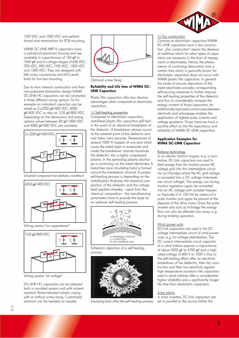
Due to their internal construction and their non-polarized termination design WIMA DC-LINK HC capacitors can be connected in three different wiring options. So for example an individual capacitor can be wired as 2 x 2250 mF/400 VDC, 4500 mF/400 VDC or also as 1125 mF/800 VDC. Depending on the dimensions and wiring options values between 85 mF/1600 VDC and 4500 mF/400 VDC are available.
2 x 2250 mF/400 VDC
Unwired component (on-delivery condition)
4500 mF/400 VDC
Wiring version “on capacitance”
1125 mF/800 VDC
Wiring version “on voltage”
DC-LINK HC capacitors can be selected both in moulded version and with solvent-resistant, flame-retardant plastic casing with or without screw fixing. Customized solutions can be realized on request.
Optional screw fixing
Reliability and Life time of WIMA DC-LINK Capacitors
Plastic film capacitors offer two decisive advantages when compared to electrolytic capacitors:
1.) Self-healing propertiesCompared to electrolytic capacitors, metallized plastic film capacitors self-heal in the event of an electrical breakdown of the dielectric. A breakdown always occurs at the weakest point of the dielectric and only takes nano-seconds. Temperatures of several 1000° K happen at one spot which cause the metal layer to evaporate and inside the breakdown channel transmute the dielectric into a highly compressed plasma. In the spreading plasma dischar-ge is continuing via the metal electrodes. A metal-free zone (insulating halo) is formed around the breakdown channel. A proper self-healing process is depending on the metallization thickness, the chemical com-position of the dielectric and the voltage level applied whereby - apart from the chemical composition - the manufacturing parameters have to provide the base for an optimum self-healing process.
b=breakdown channelc=current flowd=de-metallized area
+b
dc cd +
_
Schematic depiction of a self-healing process
Insulating halo after the self-healing process
2.) Dry constructionContrary to electrolytic capacitors WIMA DC-LINK capacitors have a dry construc-tion. „Dry construction” means the absence of additives which for other types of capa-citors are necessary in the form of impreg-nants or electrolytes. Hence, the pheno-menon of continuing desiccation over a certain time which is generally known for electrolytic capacitors does not occur with WIMA plastic film capacitors. In general the mode of vacuum deposition of the metal electrodes provides corresponding self-securing measures to further improve the self-healing properties of the dielectric and thus to considerably increase the energy content of those capacitors. An additionally improved contact area between electrode and schoopage enables the application of highest pulse currents and voltage gradients. Those measures have a positive effect on the life expectancy and reliability of WIMA DC-LINK capacitors.
Application Examples for WIMA DC-LINK Capacitors
Railway technologyIn an electric traction engine, e. g. a loco- motive, DC-Link capacitors are used to feed energy from the traction power AC voltage grid into the intermediate circuit via an H-bridge where the AC grid voltage is converted into a DC voltage (intermedi-ate circuit voltage). This energy can during traction operation again be converted into an AC voltage with variable frequen-cy (typically 0 to 150 Hz) by means of a pulse inverter and again be placed at the disposal of the drive motor. Since the pulse inverter also acts as H-bridge the energy flow can also be effected vice versa, e. g. during braking operation.
Wind power unitsDC-Link capacitors are used in the DC voltage intermediate circuit of wind power units, e. g. for voltage stabilization. The DC current intermediate circuit capacitor of a wind turbine requires a capacitance of about 3300 mF to 4700 mF and a high rated voltage of 600 V to 1000 V. Due to the self-healing effect after an electrical breakdown of the dielectric, their dry cons-truction and their low sensitivity against high temperature variations film capacitors used in wind turbines offer a considerably higher reliability and a significantly longer life time than electrolytic capacitors.
Solar plantsIn solar inverters, DC-Link capacitors are set in parallel to the source (either the
�
11.11
solar generator directly or the intermediate batteries) prior to the buck inverter module. The capacitor is subjected to a high-fre-quency ripple voltage being superimposed to the primary DC voltage. There is only one capacitor needed in a simple two-phase solar inverter.
Additional applicationsModern circuits and control devices of electric motors in today’s drive engineering technology necessitate intermediate circuits in all kinds of applications, so for example in industrial and drive converters, frequen-cy converters for pumps and ventilation, lifting and locomotion applications, and also for servo drives for example in machi-ne tools and industrial robotics.
To answer the question which kind of capacitor is best for application in a given circuit position it is necessary to obtain
excellent knowledge of the switching mechanism of the inverter and the parasitic shares of the circuit. The synthesis of a constant sinusoidal voltage for connection to the public or local mains requires high switching rates in different inverter valve combinations so that the output current can follow the sinusoidal current desired. The ripple depends on the DC voltage, the inductivity of the circuit and the switching duration. The switching frequency of a modern inverter based on IGBT technology is typically between 1 kHz and 20 kHz. The ripple current of a two-phase or three-phase track adds up and may cause severe damage to the generator and any other element switched on (e. g. batteries). The intermediate circuit capacitor is thus needed to absorb the switching ripples. That is why the DC-Link capacitor is the most important passive component in inver-ter circuits as it is the component decisive
for the total life time of the device.
Conclusion
In modern drive engineering the intermedi-ate circuit capacitor manufactured on the basis of metallized low-loss polypropylene film scores with its robustness, its insensiti-vity against high temperatures and its tem-perature adaptability. Above all, in cases where a high load transfer by an increa-sing intermediate circuit voltage occurs, reliable operation at high life time is per-mitted even without susceptible cascading of capacitances. Its tolerance towards highest ripple currents and the option of a low-inductive construction - values of approx. 10 nH at a capacitance of 1000 mFare possible - enable a low-resonance frequency response which is advantageous for the entire circuit.
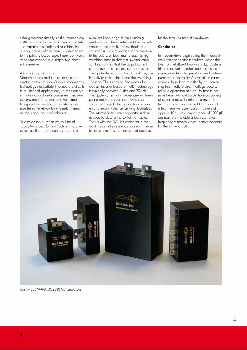
Customized WIMA DC-LINK HC capacitors

�
11.11
WIMA DC-LINK MKP �
Metallized Polypropylene (PP) Capacitors for DC-Link Applications
Special Features Electrical Data
Packing
Transportation-safe packing in cardboard boxes.Packing units:
For further details and graphs please refer to Technical Information in the main catalogue.
L pcs. per packing unit
31.5 100 41.5 100 57 50
˜ Capacitances up to 1�0 mF ˜ High volume/capacitance ratio ˜ Excellent self-healing properties ˜ Very low dissipation factor ˜ High reliability ˜ �-pin and �-pin contact configuration (plate versions on request) ˜ According to RoHS �00�/9�/EC
Typical Applications
As intermediate circuit capacitor e. g. in high power converter technology, power supplies, solar inverters etc.
Construction
Dielectric:Polypropylene (PP) filmCapacitor electrodes:Vacuum-depositedInternal construction:
Plastic film
Vacuum-depositedelectrodeMetal contact layer(schoopage)
Termination
Encapsulation:Solvent-resistant, flame-retardant plastic case with epoxy resin seal, UL 94 V-0Terminations:Tinned wire (plate versions on request).Marking:Colour: Red. Marking: Black. Epoxy resin seal: Red
Capacitance range: 2 mF to 150 mFRated voltages: 600 VDC, 800 VDC, 900 VDC, 1100 VDC, 1300 VDCCapacitance tolerances: ±20%, ±10%, ±5% Operating temperature range:–55+ C to +105+ C (hot spot including self-heating)Climatic test category: 55/085/56 in accordance with IECInsulation resistance at +20+ C: 30 000 sec (M¸ x mF)(mean value: 100 000 sec)Measuring voltage: 100 V/1 min.Dissipation factors at +20° C:tan d 10 x 10-4 at 1 kHz (C 50 mF)tan d 15 x 10-4 at 1 kHz (C 50 mF)Test voltage: 1.2 Ur, 2sec Dielectric absorption: 0.05 % Voltage and current derating:A derating factor of 1.35% per K must be applied from +85° C for DC voltages and from +70° C for AC currents (Irms). Addition- ally a derating factor of 4.5% per K must be applied from +85° C for AC currents (Irms)Maximum pulse rise time for pulses equal to the rated voltage:
PCM
max. pulse rise time V/msec at TA < 40) C 600 VDC 800 VDC 900 VDC 1100 VDC 1300 VDC
27.5 19 21 25 31 36 37.5 14 15 16 21 25 52.5 10 12 13 15 18
Reliability: Operational life 100 000 hours (Ur and 70) C) Failure rate l0 (0.5 x Ur and 40) C)
P = CN [mF] x Ur [V] l0
P 10 000 < 2 fit 10 000 < P 25 000 < 5 fit 25 000 < P 50 000 < 10 fit 50 000 < P 100 000 < 20 fit P > 100 000 < 30 fit
Specific dissipation:
Box size Specific dissipation in Watts per K W x H x L in mm above the ambient temperature
19 x 32 x 41,5 0.054 20 x 39.5 x 41.5 0.065 24 x 45.5 x 41.5 0.080 31 x 46 x 41.5 0.092 35 x 50 x 41.5 0.106 40 x 55 x 41.5 0.123 35 x 50 x 57 0.132 45 x 55 x 57 0.164 45 x 65 x 57 0.184
* other box sizes see main catalogue.

�
11.11
Capacitance600 VDC (70° C) / 450 VDC (85° C)
W H L PCM** Pin ISA
Irms (10 kHz)*A
ESR (10 kHz)*m¸
Part number
2 mF 9 19 31.5 27.5 2 38 2 56 DCP4I042006A_ _ _ _ _ _ 5 „ 13 24 31.5 27.5 2 95 3.5 22 DCP4I045006D_ _ _ _ _ _ 7 „ 15 26 31.5 27.5 2 133 4.5 16 DCP4I047006F_ _ _ _ _ _ 10 mF 17 29 31.5 27.5 2 190 6 11 DCP4I051006G_ _ _ _ _ _ 15 „ 17 34,5 31.5 27.5 2 285 7.5 7.4 DCP4I051506I_ _ _ _ _ _ 20 „ 20 39,5 31.5 27.5 2 380 9 6.2 DCP4I052006J_ _ _ _ _ _
20 39,5 41.5 37.5 2/4 280 10 6.2 DCP4I052007G_ _ _ _ _ _ 25 „ 20 39,5 41.5 37.5 2/4 350 11.5 5 DCP4I052507G_ _ _ _ _ _ 30 „ 24 45,5 41.5 37.5 2/4 420 14 4.1 DCP4I053007H_ _ _ _ _ _ 35 „ 24 45,5 41.5 37.5 2/4 490 14.5 3.8 DCP4I053507H_ _ _ _ _ _ 40 „ 31 46 41.5 37.5 2/4 560 16.5 3.3 DCP4I054007I_ _ _ _ _ _ 45 „ 31 46 41.5 37.5 2/4 630 17 3.2 DCP4I054507I_ _ _ _ _ _ 50 „ 35 50 41.5 37.5 2/4 700 19 2.9 DCP4I055007J_ _ _ _ _ _ 55 „ 35 50 41.5 37.5 2/4 770 17 3.8 DCP4I055507J_ _ _ _ _ _ 60 „ 35 50 41.5 37.5 2/4 840 17.5 3.4 DCP4I056007J_ _ _ _ _ _ 65 „ 40 55 41.5 37.5 2/4 910 19.5 3.3 DCP4I056507K_ _ _ _ _ _
35 50 57 52.5 4 650 20 3.3 DCP4I056508A_ _ _ _ _ _ 70 „ 40 55 41.5 37.5 2/4 980 20 3.1 DCP4I057007K_ _ _ _ _ _
35 50 57 52.5 4 700 20.5 3.1 DCP4I057008A_ _ _ _ _ _ 75 „ 40 55 41.5 37.5 2/4 1050 20.5 3 DCP4I057507K_ _ _ _ _ _
35 50 57 52.5 4 750 21 3 DCP4I057508A_ _ _ _ _ _ 80 „ 40 55 41.5 37.5 2/4 1120 22 2.6 DCP4I058007K_ _ _ _ _ _
35 50 57 52.5 4 800 22 2.6 DCP4I058008A_ _ _ _ _ _ 85 „ 35 50 57 52.5 4 850 22.5 2.1 DCP4I058508A_ _ _ _ _ _ 90 „ 35 50 57 52.5 4 900 23.5 1.9 DCP4I059008A_ _ _ _ _ _ 95 „ 45 55 57 52.5 4 950 24 2.8 DCP4I059508B_ _ _ _ _ _100 mF 45 55 57 52.5 4 1000 25 2.6 DCP4I061008B_ _ _ _ _ _110 „ 45 55 57 52.5 4 1100 26.5 2.3 DCP4I061108B_ _ _ _ _ _115 „ 45 65 57 52.5 4 1150 27.5 2.5 DCP4I061158C_ _ _ _ _ _120 „ 45 65 57 52.5 4 1200 28 2.3 DCP4I061208C_ _ _ _ _ _130 „ 45 65 57 52.5 4 1300 29.5 2.1 DCP4I061308C_ _ _ _ _ _140 „ 45 65 57 52.5 4 1400 31 1.9 DCP4I061408C_ _ _ _ _ _150 „ 45 65 57 52.5 4 1500 33 1.7 DCP4I061508C_ _ _ _ _ _
New box sizes, values and ranges.
* General guide
** PCM = Printed circuit module = pin spacing
Dims. in mm.
�-pin version �-pin version
Rights reserved to amend design data without prior notification.
Part number completion:
Version code: 2-pin = D2 4-pin = D4 Tolerance: 20 % = M 10 % = K 5 % = J Packing: bulk = S Pin length: 6-2 = SD
PCM d
27.5 0.8 37.5 1
W PCM b d c
19 37.5 12.5 1 0.4 20 37.5 12.5 1 0.4 24 37.5 12.5 1 0.4 31 37.5 20 1 0.4 35 37.5 20 1 0.4 40 37.5 20 1 0.4 35 52.5 20 1.2 0.8 45 52.5 20 1.2 0.8
WIMA DC-LINK MKP �
Continuation next page
pin pinpinc c
Continuation
General Data
�
11.11 Continuation next page
WIMA DC-LINK MKP �Continuation
General Data
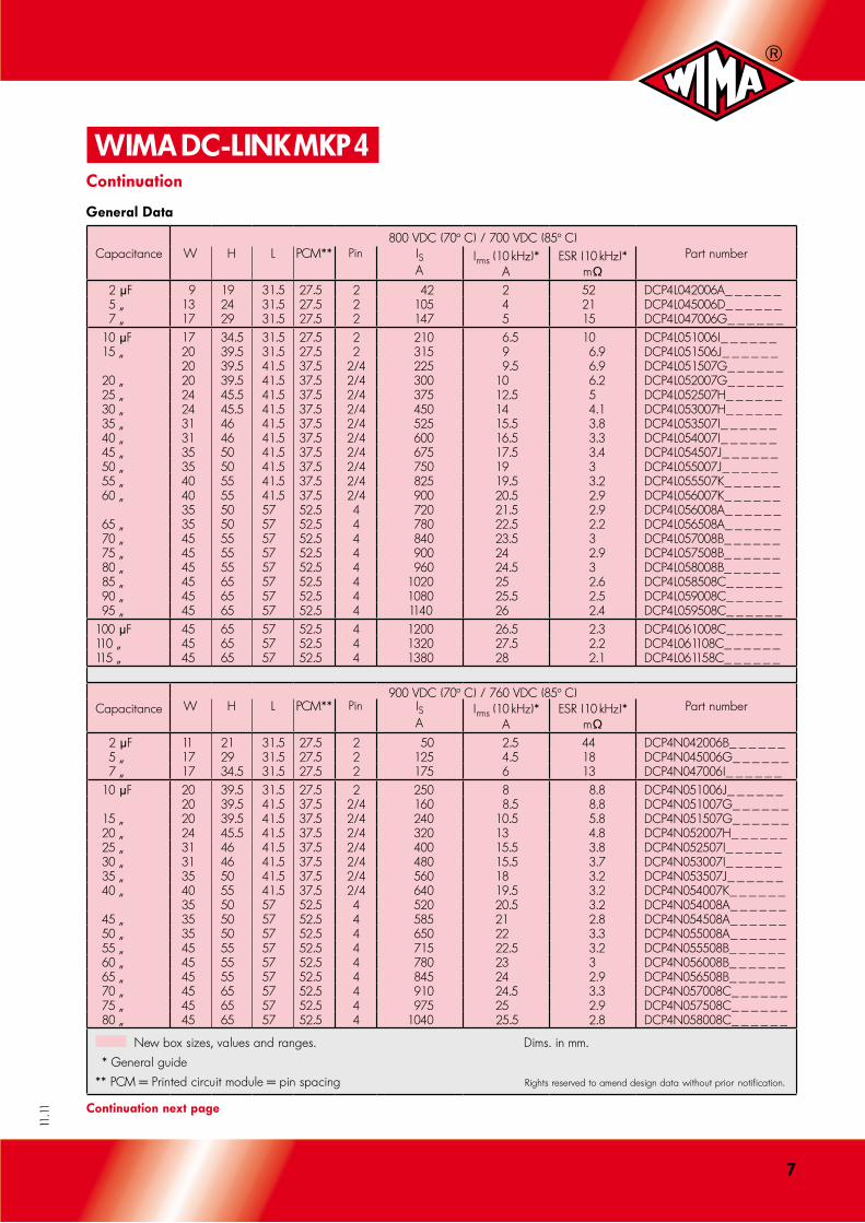
Capacitance800 VDC (70° C) / 700 VDC (85° C)
W H L PCM** Pin ISA
Irms (10 kHz)*A
ESR (10 kHz)*m¸
Part number
2 mF 9 19 31.5 27.5 2 42 2 52 DCP4L042006A_ _ _ _ _ _ 5 „ 13 24 31.5 27.5 2 105 4 21 DCP4L045006D_ _ _ _ _ _ 7 „ 17 29 31.5 27.5 2 147 5 15 DCP4L047006G_ _ _ _ _ _ 10 mF 17 34.5 31.5 27.5 2 210 6.5 10 DCP4L051006I_ _ _ _ _ _ 15 „ 20 39.5 31.5 27.5 2 315 9 6.9 DCP4L051506J_ _ _ _ _ _
20 39.5 41.5 37.5 2/4 225 9.5 6.9 DCP4L051507G_ _ _ _ _ _ 20 „ 20 39.5 41.5 37.5 2/4 300 10 6.2 DCP4L052007G_ _ _ _ _ _ 25 „ 24 45.5 41.5 37.5 2/4 375 12.5 5 DCP4L052507H_ _ _ _ _ _ 30 „ 24 45.5 41.5 37.5 2/4 450 14 4.1 DCP4L053007H_ _ _ _ _ _ 35 „ 31 46 41.5 37.5 2/4 525 15.5 3.8 DCP4L053507I_ _ _ _ _ _ 40 „ 31 46 41.5 37.5 2/4 600 16.5 3.3 DCP4L054007I_ _ _ _ _ _ 45 „ 35 50 41.5 37.5 2/4 675 17.5 3.4 DCP4L054507J_ _ _ _ _ _ 50 „ 35 50 41.5 37.5 2/4 750 19 3 DCP4L055007J_ _ _ _ _ _ 55 „ 40 55 41.5 37.5 2/4 825 19.5 3.2 DCP4L055507K_ _ _ _ _ _ 60 „ 40 55 41.5 37.5 2/4 900 20.5 2.9 DCP4L056007K_ _ _ _ _ _
35 50 57 52.5 4 720 21.5 2.9 DCP4L056008A_ _ _ _ _ _ 65 „ 35 50 57 52.5 4 780 22.5 2.2 DCP4L056508A_ _ _ _ _ _ 70 „ 45 55 57 52.5 4 840 23.5 3 DCP4L057008B_ _ _ _ _ _ 75 „ 45 55 57 52.5 4 900 24 2.9 DCP4L057508B_ _ _ _ _ _ 80 „ 45 55 57 52.5 4 960 24.5 3 DCP4L058008B_ _ _ _ _ _ 85 „ 45 65 57 52.5 4 1020 25 2.6 DCP4L058508C_ _ _ _ _ _ 90 „ 45 65 57 52.5 4 1080 25.5 2.5 DCP4L059008C_ _ _ _ _ _ 95 „ 45 65 57 52.5 4 1140 26 2.4 DCP4L059508C_ _ _ _ _ _100 mF 45 65 57 52.5 4 1200 26.5 2.3 DCP4L061008C_ _ _ _ _ _110 „ 45 65 57 52.5 4 1320 27.5 2.2 DCP4L061108C_ _ _ _ _ _115 „ 45 65 57 52.5 4 1380 28 2.1 DCP4L061158C_ _ _ _ _ _
Capacitance900 VDC (70° C) / 760 VDC (85° C)
W H L PCM** Pin ISA
Irms (10 kHz)*A
ESR (10 kHz)*m¸
Part number
2 mF 11 21 31.5 27.5 2 50 2.5 44 DCP4N042006B_ _ _ _ _ _ 5 „ 17 29 31.5 27.5 2 125 4.5 18 DCP4N045006G_ _ _ _ _ _ 7 „ 17 34.5 31.5 27.5 2 175 6 13 DCP4N047006I_ _ _ _ _ _ 10 mF 20 39.5 31.5 27.5 2 250 8 8.8 DCP4N051006J_ _ _ _ _ _
20 39.5 41.5 37.5 2/4 160 8.5 8.8 DCP4N051007G_ _ _ _ _ _ 15 „ 20 39.5 41.5 37.5 2/4 240 10.5 5.8 DCP4N051507G_ _ _ _ _ _ 20 „ 24 45.5 41.5 37.5 2/4 320 13 4.8 DCP4N052007H_ _ _ _ _ _ 25 „ 31 46 41.5 37.5 2/4 400 15.5 3.8 DCP4N052507I_ _ _ _ _ _ 30 „ 31 46 41.5 37.5 2/4 480 15.5 3.7 DCP4N053007I_ _ _ _ _ _ 35 „ 35 50 41.5 37.5 2/4 560 18 3.2 DCP4N053507J_ _ _ _ _ _ 40 „ 40 55 41.5 37.5 2/4 640 19.5 3.2 DCP4N054007K_ _ _ _ _ _
35 50 57 52.5 4 520 20.5 3.2 DCP4N054008A_ _ _ _ _ _ 45 „ 35 50 57 52.5 4 585 21 2.8 DCP4N054508A_ _ _ _ _ _ 50 „ 35 50 57 52.5 4 650 22 3.3 DCP4N055008A_ _ _ _ _ _ 55 „ 45 55 57 52.5 4 715 22.5 3.2 DCP4N055508B_ _ _ _ _ _ 60 „ 45 55 57 52.5 4 780 23 3 DCP4N056008B_ _ _ _ _ _ 65 „ 45 55 57 52.5 4 845 24 2.9 DCP4N056508B_ _ _ _ _ _ 70 „ 45 65 57 52.5 4 910 24.5 3.3 DCP4N057008C_ _ _ _ _ _ 75 „ 45 65 57 52.5 4 975 25 2.9 DCP4N057508C_ _ _ _ _ _ 80 „ 45 65 57 52.5 4 1040 25.5 2.8 DCP4N058008C_ _ _ _ _ _
New box sizes, values and ranges. Dims. in mm.
* General guide
** PCM = Printed circuit module = pin spacing Rights reserved to amend design data without prior notification.

�
11.11
Capacitance1100 VDC (70° C) / 920 VDC (85° C)
W H L PCM** Pin ISA
Irms (10 kHz)*A
ESR (10 kHz)*m¸
Part number
2 mF 13 24 31.5 27.5 2 62 3 36 DCP4P042006D_ _ _ _ _ _ 5 „ 17 34.5 31.5 27.5 2 155 5.5 14 DCP4P045006I_ _ _ _ _ _ 7 „ 20 39.5 31.5 27.5 2 217 7.5 10 DCP4P047006J_ _ _ _ _ _
19 32 41.5 37.5 2/4 147 7.5 10 DCP4P047007F_ _ _ _ _ _ 10 mF 20 39.5 41.5 37.5 2/4 210 9.5 7.2 DCP4P051007G_ _ _ _ _ _ 15 „ 31 46 41.5 37.5 2/4 315 13 5.4 DCP4P051507I_ _ _ _ _ _ 20 „ 35 50 41.5 37.5 2/4 420 15 4.7 DCP4P052007J_ _ _ _ _ _ 25 „ 40 55 41.5 37.5 2/4 525 16.5 4.6 DCP4P052507K_ _ _ _ _ _ 30 „ 35 50 57 52.5 4 450 17.5 4.4 DCP4P053008A_ _ _ _ _ _ 35 „ 35 50 57 52.5 4 525 18 4 DCP4P053508A_ _ _ _ _ _ 40 „ 45 55 57 52.5 4 600 19 4.5 DCP4P054008B_ _ _ _ _ _ 45 „ 45 55 57 52.5 4 675 20 4.1 DCP4P054508B_ _ _ _ _ _ 50 „ 45 65 57 52.5 4 750 21 4.1 DCP4P055008C_ _ _ _ _ _ 55 „ 45 65 57 52.5 4 825 22 3.8 DCP4P055508C_ _ _ _ _ _ 60 „ 45 65 57 52.5 4 900 23 3.5 DCP4P056008C_ _ _ _ _ _
Capacitance1300 VDC (70° C) / 1100 VDC (85° C)
W H L PCM** Pin ISA
Irms (10 kHz)*A
ESR (10 kHz)*m¸
Part number
2 mF 15 26 31.5 27.5 2 72 3 36 DCP4R242006F_ _ _ _ _ _ 5 „ 20 39.5 31.5 27.5 2 180 6 14 DCP4R245006J_ _ _ _ _ _
20 39.5 41.5 37.5 2/4 125 7 14 DCP4R245007G_ _ _ _ _ _ 7 „ 20 39.5 41.5 37.5 2/4 175 8 10 DCP4R247007G_ _ _ _ _ _ 10 mF 24 45.5 41.5 37.5 2/4 250 10.5 7.2 DCP4R251007H_ _ _ _ _ _ 15 „ 31 46 41.5 37.5 2/4 375 14 4.8 DCP4R251507I_ _ _ _ _ _ 20 „ 40 55 41.5 37.5 2/4 500 17.5 4 DCP4R252007K_ _ _ _ _ _
35 50 57 52.5 4 360 18 4 DCP4R252008A_ _ _ _ _ _ 25 „ 35 50 57 52.5 4 450 19 3.6 DCP4R252508A_ _ _ _ _ _ 30 „ 45 55 57 52.5 4 540 20 4 DCP4R253008B_ _ _ _ _ _ 35 „ 45 65 57 52.5 4 630 21 4.1 DCP4R253508C_ _ _ _ _ _ 40 „ 45 65 57 52.5 4 720 22 3.7 DCP4R254008C_ _ _ _ _ _
New box sizes, values and ranges.
* General guide
** PCM = Printed circuit module = pin spacing
Dims. in mm.
�-pin version �-pin version
Rights reserved to amend design data without prior notification.
pin pinpinc c
WIMA DC-LINK MKP �Continuation
General Data
Part number completion:
Version code: 2-pin = D2 4-pin = D4 Tolerance: 20 % = M 10 % = K 5 % = J Packing: bulk = S Pin length: 6-2 = SD
W PCM b d c
19 37.5 12.5 1 0.4 20 37.5 12.5 1 0.4 24 37.5 12.5 1 0.4 31 37.5 20 1 0.4 35 37.5 20 1 0.4 40 37.5 20 1 0.4 35 52.5 20 1.2 0.8 45 52.5 20 1.2 0.8
PCM d
27.5 0.8 37.5 1
9
11.11
WIMA DC-LINK MKP � NEW
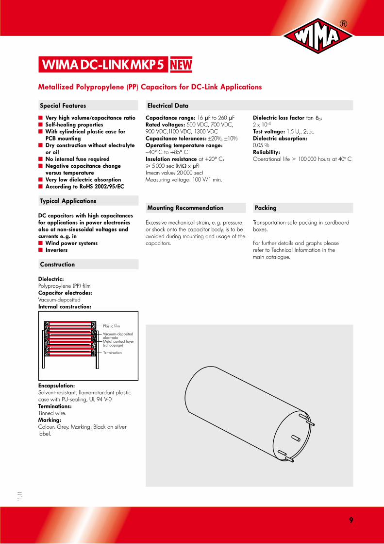
Metallized Polypropylene (PP) Capacitors for DC-Link Applications
Special Features Electrical Data
Mounting Recommendation
Excessive mechanical strain, e. g. pressure or shock onto the capacitor body, is to be avoided during mounting and usage of the capacitors.
Packing
Transportation-safe packing in cardboard boxes.
For further details and graphs please refer to Technical Information in the main catalogue.
˜ Very high volume/capacitance ratio ˜ Self-healing properties ˜ With cylindrical plastic case for PCB mounting ˜ Dry construction without electrolyte or oil ˜ No internal fuse required ˜ Negative capacitance change versus temperature ˜ Very low dielectric absorption ˜ According to RoHS �00�/9�/EC
Typical Applications
DC capacitors with high capacitances for applications in power electronics also at non-sinusoidal voltages and currents e. g. in ˜ Wind power systems ˜ Inverters
Construction
Dielectric:Polypropylene (PP) filmCapacitor electrodes:Vacuum-depositedInternal construction:
Plastic film
Vacuum-depositedelectrodeMetal contact layer(schoopage)
Termination
Encapsulation:Solvent-resistant, flame-retardant plastic case with PU-sealing, UL 94 V-0 Terminations:Tinned wire.Marking:Colour: Grey. Marking: Black on silver label.
Capacitance range: 16 mF to 260 mFRated voltages: 500 VDC, 700 VDC, 900 VDC,1100 VDC, 1300 VDCCapacitance tolerances: ±20%, ±10%Operating temperature range:–40+ C to +85+ CInsulation resistance at +20+ C: 5 000 sec (M¸ x mF)(mean value: 20 000 sec)Measuring voltage: 100 V/1 min.
Dielectric loss factor tan d0: 2 x 10⁻⁴
Test voltage: 1.5 Ur, 2sec Dielectric absorption: 0.05 % Reliability:Operational life 100 000 hours at 40° C

10
11.11
UR CND x L mm
Irms (1 kHz)**A
ESR (1 kHz)**m¸
Approx. weight g
Part number
500 VDC 85 mF
195 „ 260 „
50 x 57 50 x 95 50 x 120
35 32 30
2.0 3.4 5.2
120 190 220
DCP5H15850D000_ _ _ _ DCP5H16195D100_ _ _ _ DCP5H16260D200_ _ _ _
700 VDC 59 mF
143 „ 190 „
50 x 57 50 x 95 50 x 120
30 32 25
1.9 3.5 4.7
120 190 220
DCP5K05590D000_ _ _ _ DCP5K06143D100_ _ _ _ DCP5K06190D200_ _ _ _
900 VDC 53 mF
114 „ 158 „
50 x 57 50 x 95 50 x 120
35 32 30
2.3 4.2 6.0
120 190 220
DCP5N05530D000_ _ _ _ DCP5N06114D100_ _ _ _ DCP5N06158D200_ _ _ _
1100 VDC 30 mF
72 „ 100 „
50 x 57 50 x 95 50 x 120
20 25 25
2.8 4.5 6.1
120 190 220
DCP5P05300D000_ _ _ _ DCP5P05720D100_ _ _ _ DCP5P06100D200_ _ _ _
1300 VDC 16 mF
40 „ 55 „
50 x 57 50 x 95 50 x 120
20 25 25
3.0 5.7 7.7
120 190 220
DCP5R25160D000_ _ _ _ DCP5R25400D100_ _ _ _ DCP5R25550D200_ _ _ _
** General guide
Dims. in mm.
Rights reserved to amend design data without prior notification.
D L
50 57 50 95 50 120
WIMA DC-LINK MKP �Continuation
General Data
Part number completion:
Tolerance: 20 % = M 10 % = K Packing: bulk = S Pin length: none = 00

11
11.11
WIMA DC-LINK MKP � NEW
Metallized Polypropylene (PP) Capacitors for DC-Link Applications
Special Features Electrical Data
Mounting Recommendation
Excessive mechanical strain, e. g. pressure or shock onto the capacitor body, is to be avoided during mounting and usage of the capacitors.
Packing
Transportation-safe packing in cardboard boxes.
For further details and graphs please refer to Technical Information in the main catalogue.
˜ Very high volume/capacitance ratio ˜ Self-healing properties ˜ With cylindrical aluminium case for bus bar mounting ˜ Dry construction without electrolyte or oil ˜ No internal fuse required ˜ Negative capacitance change versus temperature ˜ Very low dielectric absorption ˜ According to RoHS �00�/9�/EC
Typical Applications
DC capacitors with high capacitances for applications in power electronics also at non-sinusoidal voltages and currents e. g. in ˜ Wind power systems ˜ Inverters
Construction
Dielectric:Polypropylene (PP) filmCapacitor electrodes:Vacuum-depositedInternal construction:
Plastic film
Vacuum-depositedelectrodeMetal contact layer(schoopage)
Termination
Encapsulation:Aluminium case with PU-sealing, UL 94 V-0 Terminations:Screw connection M6, screw bolt M12 x 16.Marking:Colour: Metallic. Marking: Black on silver label.
Capacitance range: 165 mF to 1560 mFRated voltages: 600 VDC, 700 VDC, 900 VDC,1100 VDC, 1300 VDC, 1500 VDCCapacitance tolerances: ±20%, ±10%Operating temperature range:–40+ C to +85+ CInsulation resistance at +20+ C: 5 000 sec (M¸ x mF)(mean value: 20 000 sec)Measuring voltage: 100 V/1 min.
Dielectric loss factor tan d0: 2 x 10⁻⁴
Test voltage: 1.5 Ur, 2sec Dielectric absorption: 0.05 % Reliability:Operational life 100 000 hours at 40° C

1�
11.11
UR CND x L mm
Irms (max.)**A
ESR (1 kHz)**m¸
Approx. weight g
Part number
600 VDC 780 mF
1000 „ 1560 „
85 x 120 85 x 132 85 x 210
30 35 60
1.6 1.7 1.3
700 850 1400
DCP6I06780E000_ _ _ _ DCP6I07100E100_ _ _ _ DCP6I07156E200_ _ _ _
700 VDC 585 mF
750 „ 1170 „
85 x 120 85 x 132 85 x 210
30 35 60
1.7 1.9 1.3
700 850 1400
DCP6K06585E000_ _ _ _ DCP6K06750E100_ _ _ _ DCP6K07117E200_ _ _ _
900 VDC 480 mF
550 „ 900 „
85 x 120 85 x 132 85 x 210
30 36 60
1.7 1.8 1.5
700 850 1400
DCP6N06480E000_ _ _ _ DCP6N06550E100_ _ _ _ DCP6N06900E200_ _ _ _
1100 VDC 325 mF
420 „ 650 „
85 x 120 85 x 132 85 x 210
30 40 60
1.8 1.9 1.3
700 850 1400
DCP6P06325E000_ _ _ _ DCP6P06420E100_ _ _ _ DCP6P06650E200_ _ _ _
1300 VDC 215 mF
270 „ 430 „
85 x 120 85 x 132 85 x 210
30 40 60
1.8 2.4 1.5
700 850 1400
DCP6R26215E000_ _ _ _ DCP6R26270E100_ _ _ _ DCP6R26430E200_ _ _ _
1500 VDC 165 mF
210 „ 330 „
85 x 120 85 x 132 85 x 210
30 40 60
2.2 2.5 1.7
700 850 1400
DCP6S06165E000_ _ _ _ DCP6S06210E100_ _ _ _ DCP6S06330E200_ _ _ _
** General guide
Dims. in mm.
Rights reserved to amend design data without prior notification.
Part number completion:
Tolerance: 20 % = M 10 % = K Packing: bulk = S Pin length: none = 00
D D1 L
85 86 120 85 86 132 85 86 210
WIMA DC-LINK MKP �Continuation
General Data

1�
11.11
WIMA DC-LINK HC
Metallized Polypropylene (PP) Capacitors for DC-Link Applications
Special Features Electrical Data
˜ Very high volume/capacitance ratio ˜ Self-healing, internal safety disconnector ˜ Versatile and safe contact configurations by screwable plates ˜ Dry construction without electrolyte or oil ˜ Very low disipation factor ˜ Negative capacitance change versus temperature ˜ Very low dielectric absorption ˜ According to RoHS �00�/9�/EC
Typical Applications
As intermediate circuit capacitor e. g. in high power converter technology
Construction
Dielectric:Polypropylene (PP) filmCapacitor electrodes:Vacuum-depositedInternal construction:
Encapsulation:Solvent resistant, flame-retardant plastic case with resin seal (optional screw fixing) or moulded version (without screw fixing), UL 94 V-0.Terminations:Tinned plates, customized plate configurations are possible.Marking:Colour: Black. Marking: Gold.
Capacitance range:85 mF to 4500 mFRated voltages:400 VDC, 800 VDC, 1600 VDCCapacitance tolerances:±20%, ±10%, (±5% available subject to special enquiry)Operating temperature:–55+ C to +85° C Insulation resistance at +20+ C: 30 000 sec (M¸ x mF)(mean value: 100 000 sec)Measuring voltage: 100 V/1 min.Dissipation factors at +20° C:See General Data.
Test voltage: 1.1 Ur , 2 sec Dielectric absorption: 0.05 % Voltage derating:A voltage derating factor of 1.35 % per K must be applied from +85° C for DC voltages and from +75° C for AC voltages. Reliability:Operational life 100 000 hours at 40° C Failure rate 36 fit (0.5 x Ur and 40) C)Specific dissipation: See General Data.
Mounting Recommendation
Excessive mechanical strain, e. g. pressure or shock onto the capacitor body, is to be avoided during mounting and usage of the capacitors. When fixing the capacitor the screw torque is to be limited to max. 5 Nm.
Packing
Transportation-safe packing in cardboard boxes.
For further details and graphs please refer to Technical Information in the main catalogue.
1�
11.11
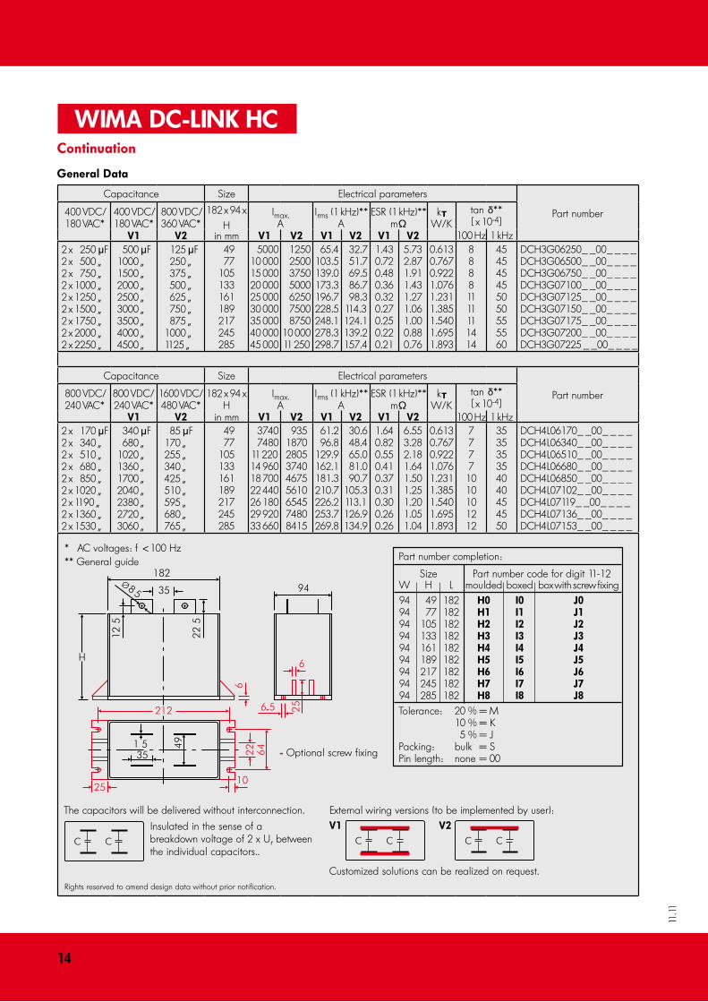
Capacitance Size Electrical parameters
Part number400 VDC/ 180 VAC*
400 VDC/ 180 VAC*
800 VDC/ 360 VAC*
182 x 94 xH
Imax.A
Irms (1 kHz)**A
ESR (1 kHz)**m¸
ktW/K
tan d** [ x 10-4]
100 Hz 1 kHzV1 V� in mm V1 V� V1 V� V1 V�2 x 250 mF2 x 500 „2 x 750 „2 x 1000 „2 x 1250 „2 x 1500 „2 x 1750 „2 x 2000 „2 x 2250 „
500 mF1000 „1500 „2000 „2500 „3000 „3500 „4000 „4500 „
125 mF 250 „ 375 „ 500 „ 625 „ 750 „ 875 „1000 „1125 „
49 77105133161189217245285
500010 00015 00020 00025 00030 00035 00040 00045 000
1250 2500 3750 5000 6250 7500 875010 00011 250
65.4103.5139.0173.3196.7228.5248.1278.3298.7
32.7 51.7 69.5 86.7 98.3114.3124.1139.2157.4
1.430.720.480.360.320.270.250.220.21
5.732.871.911.431.271.061.000.880.76
0.6130.7670.9221.0761.2311.3851.5401.6951.893
88881111111414
454545455050555560
DCH3G06250_ _00_ _ _ _DCH3G06500_ _00_ _ _ _DCH3G06750_ _00_ _ _ _DCH3G07100_ _00_ _ _ _DCH3G07125_ _00_ _ _ _DCH3G07150_ _00_ _ _ _DCH3G07175_ _00_ _ _ _DCH3G07200_ _00_ _ _ _DCH3G07225 _ _00_ _ _ _
Capacitance Size Electrical parameters
Part number800 VDC/ 240 VAC*
800 VDC/ 240 VAC*
1600 VDC/ 480 VAC*
182 x 94 xH
Imax.A
Irms (1 kHz)**A
ESR (1 kHz)**m¸
ktW/K
tan d** [ x 10-4]
100 Hz 1 kHzV1 V� in mm V1 V� V1 V� V1 V�2 x 170 mF2 x 340 „2 x 510 „2 x 680 „2 x 850 „2 x 10²⁰ „2 x 1190 „2 x 1360 „2 x 1530 „
340 mF 680 „1020 „1360 „1700 „2040 „2380 „2720 „3060 „
85 mF170 „255 „340 „425 „510 „595 „680 „765 „
49 77105133161189217245285
3740 748011 22014 96018 70022 44026 18029 92033 660
93518702805374046755610654574808415
61.2 96.8129.9162.1181.3210.7226.2253.7269.8
30.6 48.4 65.0 81.0 90.7105.3113.1126.9134.9
1.640.820.550.410.370.310.300.260.26
6.553.282.181.641.501.251.201.051.04
0.6130.7670.9221.0761.2311.3851.5401.6951.893
7777
1010101212
353535354040454550
DCH4L06170_ _00_ _ _ _DCH4L06340_ _00_ _ _ _DCH4L06510_ _00_ _ _ _DCH4L06680_ _00_ _ _ _DCH4L06850_ _00_ _ _ _DCH4L07102_ _00_ _ _ _DCH4L07119_ _00_ _ _ _DCH4L07136_ _00_ _ _ _DCH4L07153_ _00_ _ _ _
* AC voltages: f < 100 Hz** General guide
- Optional screw fixing
Rights reserved to amend design data without prior notification.
WIMA DC-LINK HC
External wiring versions (to be implemented by user):V1 V�
Customized solutions can be realized on request.
The capacitors will be delivered without interconnection.
Insulated in the sense of a breakdown voltage of 2 x Ur between the individual capacitors..
Continuation
General Data
Part number completion:
Size Part number code for digit 11-12 W H L moulded boxed box with screw fixing 94 49 182 H0 I0 J0 94 77 182 H1 I1 J1 94 105 182 H� I� J� 94 133 182 H� I� J� 94 161 182 H� I� J� 94 189 182 H� I� J� 94 217 182 H� I� J� 94 245 182 H� I� J� 94 285 182 H� I� J� Tolerance: 20 % = M 10 % = K 5 % = J Packing: bulk = S Pin length: none = 00
1�
11.11
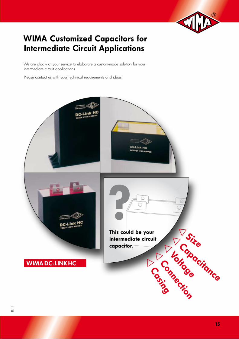
?This could be your intermediate circuit capacitor.
WIMA Customized Capacitors for Intermediate Circuit Applications
WIMA DC-LINK HC
v Sizev Capacitance
v Voltage
v Connection
v Casing
We are gladly at your service to elaborate a custom-made solution for your intermediate circuit applications.
Please contact us with your technical requirements and ideas.
1�
11.11
Printed in Germany 11/2011
WIMA-Bezugsquellen
WIMA Spezialvertrieb elektronischer Tel: +49-621-862950Bauelemente GmbH & Co. KG Fax: +49-621-8629595Pfingstweidstr. 13 E-mail: [email protected] Mannheim · Germany Internet: www.wima.com
New ranges, box sizes or values.* The insulation resistance data refers to the lowest rated voltage of each range. Further details concerning higher rated voltages see respective data sheet.* Closer tolerances are available subject to special enquiry.The values in the DC-LINK MKP 4 tables refer to the smallest PCM of the respective capacitance value. For larger PCMs please refer to the detailed data sheet of the particular series.
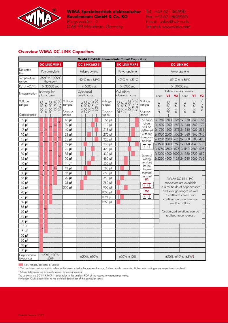
Overview WIMA DC-LINK Capacitors
WIMA DC-LINK Intermediate Circuit Capacitors
DC-LINK MKP � DC-LINK MKP � DC-LINK MKP � DC-LINK HC
Dielectric film Polypropylene Polypropylene Polypropylene Polypropylene
Temperature range
-55° C to +105° C (hot-spot) -40° C to +85° C -40° C to +85° C -55° C to +85° C
Ris*at +20° C 30 000 sec 5000 sec 5000 sec 30 000 sec
Encapsulation Rectangular plastic case
Cylindrical plastic case
Cylindrical aluminium case
External wiring version
none V1 V� none V1 V�
Voltage ranges
Capacitance
600
VDC
800
VDC
900
VDC
1100
VD
C13
00 V
DC Voltage
ranges
Capac-itance
500
VDC
700
VDC
900
VDC
1100
VD
C13
00 V
DC Voltage
ranges
Capac-itance
600
VDC
700
VDC
900
VDC
1100
VD
C13
00 V
DC
1500
VD
C Voltage ranges
Capac-itance
400
VDC
400
VDC
800
VDC
800
VDC
800
VDC
1600
VD
C
2 mF
27.527.5
27.527.5
27.5 16 mF 165 mF The capa-
citors will be
delivered without
intercon-nection
External wiring
versions (to be imple-mented by user)
V1
V�
2x 250 500 125 2x 170 340 85
5 mF 30 mF 210 mF 2x 500 1000 250 2x 340 680 170
7 mF
37.5
40 mF 215 mF 2x 750 1500 375 2x 510 1020 255
10 mF
37,5
53 mF 270 mF 2x1000 2000 500 2x 680 1360 340
15 mF
37.5
55 mF 325 mF 2x1250 2500 625 2x 850 1700 425
20 mF
37.5
59 mF 330 mF 2x1500 3000 750 2x10²⁰ 2040 510
25 mF
37.5
52.5
72 mF 420 mF 2x1750 3500 875 2x1190 2380 595
30 mF
52.5
85 mF 430 mF 2x2000 4000 1000 2x1360 2720 680
35 mF 100 mF 480 mF 2x2250 4500 1125 2x1530 3060 765
40 mF 114 mF 550 mF
45 mF
52.5
143 mF 585 mF
50 mF 158 mF 650 mF
WIMA DC-LINK HC capacitors are available
in a multitude of capacitances and voltage ranges as well
as different connection configurations and encap-
sulation options.
Customized solutions can berealized upon request.
55 mF 190 mF 750 mF
60 mF 195 mF 780 mF
65 mF
52.5
260 mF 900 mF
70 mF 1000 mF
75 mF 1170 mF
80 mF 1560 mF
85 mF
52.5
90 mF
95 mF
100 mF
110 mF
115 mF
120 mF
130 mF
140 mF
150 mF
Capacitance tolerances
±20%, ±10%, ±5% ±20%, ±10% ±20%, ±10% ±20%, ±10%, (±5%*)