bentofix geosynthetic clay liner installation and...
TRANSCRIPT

Bentofix® Installation Guideline 02a/2009
© NAUE GmbH & Co. KG . Gewerbestrasse 2 . 32339 Espelkamp-Fiestel, Germany Status: 03.02.2009 Tel. +49 5743/41-0 . Fax +49 5743/41-240 . [email protected] . www.naue.com . www.bentofix.com Page 1 of 13
Bentofix® Geosynthetic Clay Liner Installation and Acceptance Procedure
(Type B, NSP & BFG) for Landfill Applications
NAUE GmbH & Co. KG
Quality Statement ...........................................................................................................................2 Labelling ..........................................................................................................................................2 Shipping ..........................................................................................................................................2 Unloading Procedures ...................................................................................................................2 Storage ............................................................................................................................................4 Subgrade Preparation ....................................................................................................................4 Anchoring........................................................................................................................................5 Installation.......................................................................................................................................5 Overlaps and Seaming...................................................................................................................6 Attachment Details .........................................................................................................................8 Repairs.............................................................................................................................................8 Inspection........................................................................................................................................9 Cover Material .................................................................................................................................9 General and Safety Precautions .................................................................................................11 Appendix: A – On-Site Inspection – GCL, Storage, Equipment, Acceptance, Installation......................12 B – List of GCL Rolls Received/Deployed..................................................................................13
The following installation recommendation contains general installation guidelines. It is presented as a general format, not as a direct substitute for a project specific drainage specification. In the event of a conflict, the requirement of the project specification will supersede these recommendations. This recommendation does not purport to address all of the safety concerns, if any, associated with its use. It is the responsibility of the user of this guideline to establish appropriate safety and health practices and determine the applicability of regulatory limitations prior to use. The information contained herein has been compiled by NAUE GmbH & Co. KG, Germany, and is, to the best of our knowledge, true and accurate. There is no implied or expressed warranty. Final determination of suitability for use contemplated is the sole responsibility of the user. This information is subject to change without notice.

Bentofix® Installation Guideline 02a/2009
© NAUE GmbH & Co. KG . Gewerbestrasse 2 . 32339 Espelkamp-Fiestel, Germany Status: 03.02.2009 Tel. +49 5743/41-0 . Fax +49 5743/41-240 . [email protected] . www.naue.com . www.bentofix.com Page 2 of 13
INSTALLATION PROCEDURES FOR BENTOFIX® GEOSYNTHETIC CLAY LINERS (GCLS) 1. QUALITY STATEMENT NAUE GmbH & Co. KG as the inventor of needle-punched GCLs in 1987 is dedicated to continuous quality. This commitment begins with the manufacture of the Bentofix® Geosynthetic Clay Liner (GCL) material and its components (as well as the quality control of these and their components), and continues until our customer has accepted the GCL. Our policy is based on the principle that quality is the fundamental responsibility of every department and is carried out by each person in that department. Programs and procedures designed to implement this quality principle are developed by the Quality Management and are utilized by every employee of the Company. After all quality assurance measures have been performed as defined in the quality assurance plan, an acceptance test certificate is issued according to EN ISO 10204 when requested. NAUE GmbH & Co. KG Manufacturing, Design, and Quality Control is fully ISO 9001 (2000) registered. 2. LABELING Each roll of geosynthetic clay liner shall be labeled with the following: - Name of manufacturer - Product Identification - Roll Dimension - Unique Roll Number - Total Mass per Unit Area - Label with handling guidelines 3. SHIPPING Bentofix® GCL rolls are delivered to the working area of the site in their original packaging. Immediately prior to deployment, the packaging shall be carefully removed without damaging the GCL. Bentofix® GCLs shall be shipped and stored in such a manner that the GCL material is protected from damage. Stacking should always allow access to at least one end of each roll. Rolls of material are handled with equipment that will not damage the GCL. Fabric straps, spreader-bar, stinger-bar, or other approved apparatus are used for handling rolls of GCL. 4. UNLOADING PROCEDURES As with any lifting or loading operations, appropriate safety equipment should be employed and proper safe handling methods practiced. The party responsible for unloading the Bentofix® GCL should contact the manufacturer prior to shipment to determine the correct unloading methods and equipment if different from the pre-approved and specified methods.

Bentofix® Installation Guideline 02a/2009
© NAUE GmbH & Co. KG . Gewerbestrasse 2 . 32339 Espelkamp-Fiestel, Germany Status: 03.02.2009 Tel. +49 5743/41-0 . Fax +49 5743/41-240 . [email protected] . www.naue.com . www.bentofix.com Page 3 of 13
Lifting the rolls can be accomplished with a 63 mm - 75 mm outside diameter (O.D.) steel pipe/bar (preferably solid), with a wall thickness capable of providing sufficient beam strength to support the weight of the roll without bending, which is (GCL type dependent) generally between 900 and 1,200 kg. The core pipe is inserted through the centre core of Bentofix®. Heavy-duty slings or chains are attached to each end of the pipe, which are then fastened to a spreader bar. A crane, backhoe, front-end loader or any other suitable piece of equipment can then lift the entire assembly. An all-terrain, extendable boom or fork lift, can be fitted with a special, solid steel pole ≥ 4.0 m in length, having an outside diameter of no more then 86 mm. The pole is inserted into the core of the Bentofix® roll. The roll should not be fully lifted until the pole extends its full length into the core so that the core does not break. This pole has a long reach and is particularly useful for unloading containers or covered vans. Bentofix® GCLs must be supported during handling to ensure workers safety and prevent damage to the liner and the core pipe. Under approved and monitored circumstances only, should the rolls be dragged, lifted from one end, lifted with only the forks of a lift truck or pushed to the ground from the delivery vehicle. The Construction Quality Assurance (CQA) inspector should verify that proper handling equipment exists which does not pose any danger to the installation crew or risk of
damage or deformation to the liner material itself. Additional handling equipment is described below:
Spreader Bar Assembly - A spreader bar assembly shall include both a core pipe or bar and a spreader beam. The core pipe shall be used to uniformly support the roll when inserted through the GCL core while the spreader beam will prevent chains or straps from chafing the roll edges.
Stinger - A stinger is a rigid pipe or rod with one end directly connected to a forklift or other handling equipment. If a stinger is used, it should be inserted to its full length into the roll to prevent excessive bending of the roll when lifted. Roller Cradles - Roller cradles consist of two large diameter rollers spaced approximately 75 mm apart which both support the GCL roll and allow it to freely unroll. The use of roller cradles shall be permitted if the rollers support the entire width of the GCL roll. Slings – Wide band slings (≥ 75 mm) may be used to support the ends of spreader bars or an additionally inserted core pipe or bar with sufficient strength to withstand the weight of the GCL roll but are not recommended as the primary support mechanism. As wide band slings may damage the Bentofix® GCL where wrapped around the roll and generally do not provide sufficient uniform support to prevent roll bending or deformation, great care must be exercised when this option is used.

Bentofix® Installation Guideline 02a/2009
© NAUE GmbH & Co. KG . Gewerbestrasse 2 . 32339 Espelkamp-Fiestel, Germany Status: 03.02.2009 Tel. +49 5743/41-0 . Fax +49 5743/41-240 . [email protected] . www.naue.com . www.bentofix.com Page 4 of 13
5. STORAGE
A storage area is required that is flat, dry, and well drained to keep the Bentofix® GCL dry. The surface should be free of sharp rocks or other objects that could damage the GCL. The storage area must be as close as practical to the work area to minimize on site handling.
The storage area must be secure to prevent vandalism, theft, and must be
such that rolls are unlikely to be damaged by passing vehicles. Rolls of Bentofix® and bentonite for the overlap areas need to be covered with a plastic sheet or tarpaulin until their installation. Any rolls that come in contact with moisture while in storage should be examined prior to installation to ensure that subsequent physical damage has not occurred. Physically damaged rolls should be set aside for further examination to determine the plausibility of repair. 6. SUBGRADE PREPARATION The surface upon which the Bentofix® GCL is installed should be smooth and free of debris, roots, sticks, and sharp rocks/boulders larger than 50 mm. Site specific compaction requirements should be followed in accordance with the project plans and specifications. At a minimum, the level of compaction should be such that installation equipment or other construction vehicles that traffic the area of deployment do not cause significant rutting. In applications where the Bentofix® GCL will be subjected to a hydraulic head that exceeds the cover soil confining stress, subgrade surfaces consisting of gravel or granular soils may not be acceptable due to their large void content (common in liquid surface impoundments; in these applications the use of Bentofix® BFG types is strongly recommended; prior to use in these applications contact a NAUE representative). For these applications, the top 150 mm of the subgrade soil should possess a particle size distribution where at least 80 percent of the soil is finer than 0.2 mm with a maximum particle size of 12 mm. Directly prior to deployment of the Bentofix® GCL, the subgrade shall be final-graded to fill in any remaining voids or desiccation cracks and proof-rolled to ensure that no sharp irregularities or abrupt elevation changes exist greater than 25 mm. The surfaces to be lined shall be maintained in this condition, free of standing water. If required the subgrade preparation and surface should be inspected and certified by a CQA inspector prior to Bentofix® GCL placement. Upon approval by the CQA inspector, it should be the installer's responsibility to indicate to the engineer any change in the condition of the subgrade that could cause it to be out of compliance with any of the requirements of the project specific specification.

Bentofix® Installation Guideline 02a/2009
© NAUE GmbH & Co. KG . Gewerbestrasse 2 . 32339 Espelkamp-Fiestel, Germany Status: 03.02.2009 Tel. +49 5743/41-0 . Fax +49 5743/41-240 . [email protected] . www.naue.com . www.bentofix.com Page 5 of 13
7. ANCHORING
Bentofix® GCL is typically anchored in a trench on the top of slopes, e.g. around the perimeter of the containment basin to provide the required pullout resistance. In most cases Bentofix® GCLs can be anchored in the same trench as any adjacent geosynthetic liner components (if used). Dimensions and location of the trench should be provided in the project drawings or from the table under the figure. Alternately, the material may be anchored by deploying additional run-out of material past the slope crest. When an anchor trench is required, it is excavated no more than two to three days ahead of GCL placement. This should prevent the trench sides from falling in and requiring re-excavation. When the panels are placed in position, the anchor trench must be loosely backfilled or loaded with sandbags
8. INSTALLATION As Bentofix® rolls are selected for deployment, the roll labels should be removed and recorded by the installer, along with any other pertinent information. The layout and sequence of panel placement is determined by direction of water run-off. Panels are laid out according to the previously approved panel layout drawings, when such drawings are available. Generally, the installation is started at the up-wind side and at the highest elevation so that any rainfall runs off the lower part of the impoundment, this prevents water from hydrating the GCL. When in position, panels are checked for any physical damage. All Bentofix® GCL rolls should be installed in a relaxed condition, and be free of wrinkles and folds. Rolls of Bentofix® material are unrolled using a front-end loader or other approved handling equipment. A spreader bar or other approved apparatus is attached to the bucket or the front of the equipment. Panels on slopes are placed so that the seam runs parallel to the direction on the slope. Flat areas are laid in no particular orientation, but the panels should be shingled in the down-slope direction to facilitate drainage. If required a smooth piece of geomembrane will be used as a rub sheet to facilitate deployment of other geosynthetic layers. The rub sheet does not need to run the entire length of the slope, only the top crest and first few feet of the slope need to be covered to facilitate deployment.

Bentofix® Installation Guideline 02a/2009
© NAUE GmbH & Co. KG . Gewerbestrasse 2 . 32339 Espelkamp-Fiestel, Germany Status: 03.02.2009 Tel. +49 5743/41-0 . Fax +49 5743/41-240 . [email protected] . www.naue.com . www.bentofix.com Page 6 of 13
NAUE GmbH & Co. KG recommends to use low ground pressure devices such as ATV´s or tractors to help facilitate deployment over other geosynthetic layers if no other method is possible. Low ground pressure devices are machines with less than 50 kN/m² per wheel when carrying a driver weighing approximately 80 kg. Using low ground pressure machines also results in a safer work environment. Utilizing such equipment may result in less exertion by field personnel thus reducing the potential for strain related injuries. Only as much Bentofix® GCL as can be covered by the end of the day should be deployed, or such amount that can be covered in a reasonably short time in the event of precipitation. Uncovered overlap edges should be protected overnight with a plastic membrane to prevent bentonite hydration (see section “Cover Material). The edges of exposed sheets should be weighted down with sandbags or equivalent ballast, which does not cause any damage to the GCL, to prevent uplift in the event of strong winds.
Cutting of Bentofix® GCLs may be required at some times, e.g. around penetrations. This can be accomplished by using a sharp utility knife. Frequent blade changes are recommended to avoid damage to the geosynthetic components of the GCL during the cutting process. Removed blades should not be discarded on or under installed Bentofix®.
9. OVERLAPS AND SEAMING Rolls of GCL are typically overlapped like roof tiles in direction of flow approximately 300 mm on panel edges and 500 mm on panel ends. T-overlaps are allowed. However, two adjacent laying end overlaps (cross overlaps) are not allowed. Rolls should be adjusted to smooth out wrinkles or creases between adjacent panels while leaving the proper overlap and be free of wrinkles, folds or “fish-mouths” when covered.
Typically Bentofix® "NSP" GCLs have 500 mm wide bentonite impregnated longitudinal edges for self sealing overlaps. No additional bentonite is needed on-site for these longitudinal seams. Bentofix® "BFG" GCLs are fully bentonite impregnated so that no
additional bentonite is required for any overlap areas. Other overlap areas require on-site bentonite treatment. These overlapping edges are pulled back and bentonite similar to that used in the product should be poured continuously along all seam edges, typically 0.4 kg/m. The required amount of overlap bentonite can be ordered from and supplied by the GCL manufacturer NAUE GmbH & Co. KG.

Bentofix® Installation Guideline 02a/2009
© NAUE GmbH & Co. KG . Gewerbestrasse 2 . 32339 Espelkamp-Fiestel, Germany Status: 03.02.2009 Tel. +49 5743/41-0 . Fax +49 5743/41-240 . [email protected] . www.naue.com . www.bentofix.com Page 7 of 13
Typically Bentofix® "B" GCLs have 500 mm wide bentonite impregnated longitudinal edges for self sealing overlaps. No additional bentonite is needed on-site for these longitudinal seams (left picture). However, it must be ensured that the bentonite impregnated overlap is fully in contacted with the 200 mm wide extending woven of the woven/nonwoven composite. If this is not the case, the overlap must be treated with additional bentonite. Other overlap areas, such as cross-width overlap areas require on-site bentonite treatment. These overlapping edges are pulled back and bentonite similar to that used in the product should be poured continuously along all seam edges, typically 0.7 kg/m (right picture). The required amount of overlap bentonite can be ordered from and supplied by the GCL manufacturer NAUE GmbH & Co. KG. Sometimes slopes are too long (in excess of 40 m) for one roll of Bentofix® GCL to cover the entire slope. In these special cases, other means must be devised to which continuity of the liner system must be preserved. In some cases, extra long rolls of GCL may be provided. However, due to handling problems caused by the extra weight, the extra long rolls may not be practical or safe. In these cases, NAUE GmbH & Co. KG recommends to place a horizontal seam across the slope if approved by the project engineer. Additionally it is possible to pin the bottom GCL to the ground in the overlap area. Details on the pins and spacing distances should be agreed on prior to use. The end overlap shall be a minimum of 500 mm. Alternatively a hidden anchor trench can be used if approved by the project engineer. When the liner is cut to fit in small areas, in corners or around structures adjacent panels should be overlapped a minimum 300 mm, adding abundant bentonite in the overlapped areas, if the overlapped area does not cover a fully bentonite impregnated area.

Bentofix® Installation Guideline 02a/2009
© NAUE GmbH & Co. KG . Gewerbestrasse 2 . 32339 Espelkamp-Fiestel, Germany Status: 03.02.2009 Tel. +49 5743/41-0 . Fax +49 5743/41-240 . [email protected] . www.naue.com . www.bentofix.com Page 8 of 13
10. ATTACHMENT DETAILS Bentofix® GCL should be installed around penetrations, pipes, and other structures according to the contract drawings and guidelines. Bentofix® may be secured to the structures by use of a stainless steel batten or clamp, mechanical fasteners, or other appropriate device if necessary for minimizing movement. Additional bentonite or bentonite paste is necessary to maximize the seal. Typical Bentofix® attachment to vertical and horizontal pipe penetrations is shown in the left picture. A typical Bentofix® attachment to a concrete structure is shown in the figure on the right. 11. REPAIRS In the event that an area of Bentofix® GCL becomes damaged, torn or punctured during installation, the affected area should be repaired. On relatively level surfaces, the damaged area should be covered with a separate piece of Bentofix® GCL extending at least 500 mm beyond the damaged area in every direction. Bentonite should be used to augment the patch overlays as is required for all other seams. Damaged GCL material on slopes shall be repaired by the same procedures, however,
the edges of the patch could also be adhered to the repaired liner with an adhesive to keep the patch in position during backfill or cover operations.
Areas that are exposed to standing water or excess precipitation with resulting excessive bentonite hydration prior to soil covering should be examined for damage by subsequent activities. If it is determined that the GCL has been hydrated and damaged, the GCL should be covered with new a new GCL piece over the affected area or removed and replaced.

Bentofix® Installation Guideline 02a/2009
© NAUE GmbH & Co. KG . Gewerbestrasse 2 . 32339 Espelkamp-Fiestel, Germany Status: 03.02.2009 Tel. +49 5743/41-0 . Fax +49 5743/41-240 . [email protected] . www.naue.com . www.bentofix.com Page 9 of 13
All Bentofix® GCL material exposed to hydrocarbon fuels, chemicals, non-compatible liquids, or other harmful liquids during the installation should be removed and replaced with non-affected Bentofix® GCL. 12. INSPECTION After deployment and seaming, a close visual inspection of the Bentofix® GCL rolls and seams shall be made by the project engineer or an approved person. This is done as soon as possible after deployment has been completed. The inspection is to include overlaps, alignments, detect any defects, including installation damage. Such areas shall be marked, repaired and the repairs shall be inspected and approved by the project engineer or an approved person. This inspection/repair process is to be carried out in a systematic manner as soon as possible to ensure that no defective area stays unrepaired. Penetrations, possible repairs, and any other details should also be visually inspected in the same manner. Once the inspection has passed the next layer of geosynthetics may be installed or the spreading of the cover soil can begin in a method not harmful to the installed GCL. 13. COVER MATERIAL Only the amount of Bentofix® GCL that can be anchored, inspected, and covered should be installed the same day or prior to any prehydration. If Bentofix® is hydrated when no confining stress is present, it may be necessary to remove and replace the hydrated GCL. In this case it is necessary to contact a NAUE representative and discuss further necessary steps if premature hydration without any confining stress on the GCL is suspected to have occurred. In cases where the Bentofix® GCL is the sole hydraulic barrier, the GCL should be
covered with the specified thickness of cover soil ≥ 300 mm immediately following deployment prior to any bentonite moisture absorption. Is the final confining stress thicker than 300 mm it is recommended to place the final confining stress within 2 weeks and prior to any wet/dry cycles of the bentonite. Care must be taken in the overlap areas. During the soil covering overlaps may not be separated.
The preferred direction of soil placement is in direction of the overlaps (see picture on the left).
On slopes a downhill soil placement is typically not recommended due to necking and interface shear strength concerns. The soil should carefully be placed uphill ensuring that the overlap areas are not separated or soil is being pushed into the overlap area. The slope stability must be ensured at all times. Where Bentofix® GCL is used in conjunction with a geomembrane component it should be covered with the geomembrane as soon as possible after placement to protect it from any
Bentofix® Installation Guideline 02a/2009
© NAUE GmbH & Co. KG . Gewerbestrasse 2 . 32339 Espelkamp-Fiestel, Germany Status: 03.02.2009 Tel. +49 5743/41-0 . Fax +49 5743/41-240 . [email protected] . www.naue.com . www.bentofix.com Page 10 of 13
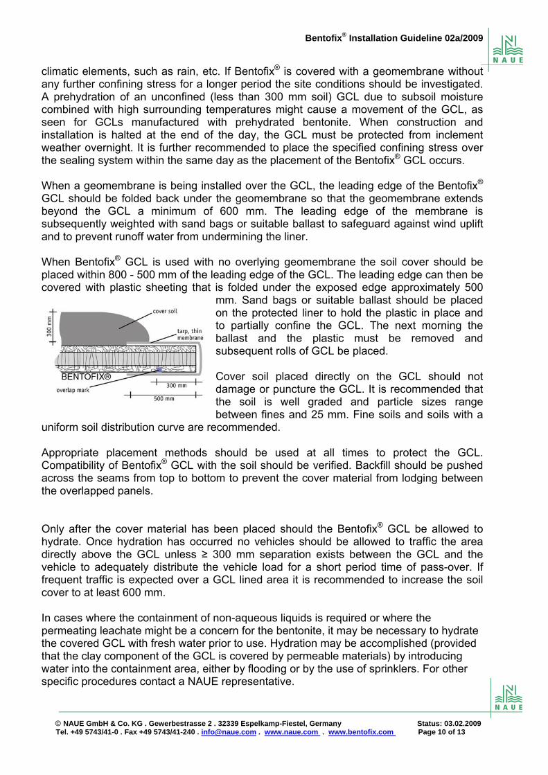
climatic elements, such as rain, etc. If Bentofix® is covered with a geomembrane without any further confining stress for a longer period the site conditions should be investigated. A prehydration of an unconfined (less than 300 mm soil) GCL due to subsoil moisture combined with high surrounding temperatures might cause a movement of the GCL, as seen for GCLs manufactured with prehydrated bentonite. When construction and installation is halted at the end of the day, the GCL must be protected from inclement weather overnight. It is further recommended to place the specified confining stress over the sealing system within the same day as the placement of the Bentofix® GCL occurs. When a geomembrane is being installed over the GCL, the leading edge of the Bentofix® GCL should be folded back under the geomembrane so that the geomembrane extends beyond the GCL a minimum of 600 mm. The leading edge of the membrane is subsequently weighted with sand bags or suitable ballast to safeguard against wind uplift and to prevent runoff water from undermining the liner. When Bentofix® GCL is used with no overlying geomembrane the soil cover should be placed within 800 - 500 mm of the leading edge of the GCL. The leading edge can then be covered with plastic sheeting that is folded under the exposed edge approximately 500
mm. Sand bags or suitable ballast should be placed on the protected liner to hold the plastic in place and to partially confine the GCL. The next morning the ballast and the plastic must be removed and subsequent rolls of GCL be placed.
Cover soil placed directly on the GCL should not damage or puncture the GCL. It is recommended that the soil is well graded and particle sizes range between fines and 25 mm. Fine soils and soils with a
uniform soil distribution curve are recommended. Appropriate placement methods should be used at all times to protect the GCL. Compatibility of Bentofix® GCL with the soil should be verified. Backfill should be pushed across the seams from top to bottom to prevent the cover material from lodging between the overlapped panels. Only after the cover material has been placed should the Bentofix® GCL be allowed to hydrate. Once hydration has occurred no vehicles should be allowed to traffic the area directly above the GCL unless ≥ 300 mm separation exists between the GCL and the vehicle to adequately distribute the vehicle load for a short period time of pass-over. If frequent traffic is expected over a GCL lined area it is recommended to increase the soil cover to at least 600 mm. In cases where the containment of non-aqueous liquids is required or where the permeating leachate might be a concern for the bentonite, it may be necessary to hydrate the covered GCL with fresh water prior to use. Hydration may be accomplished (provided that the clay component of the GCL is covered by permeable materials) by introducing water into the containment area, either by flooding or by the use of sprinklers. For other specific procedures contact a NAUE representative.

Bentofix® Installation Guideline 02a/2009
© NAUE GmbH & Co. KG . Gewerbestrasse 2 . 32339 Espelkamp-Fiestel, Germany Status: 03.02.2009 Tel. +49 5743/41-0 . Fax +49 5743/41-240 . [email protected] . www.naue.com . www.bentofix.com Page 11 of 13
14. GENERAL AND SAFETY PRECAUTIONS This installation guideline contains general installation procedures for Bentofix® GCLs. It is not intended to replace project-specific installation requirements. In the event of a conflict, the requirement of the project specifications will supersede this installation guideline. Further this installation guideline does not purport to establish specific procedure for all climatic, geographical, hydraulic, or topographical conditions that may exist at a site. Appropriate installation procedures under atypical field conditions should be modified as necessary to maintain the integrity of the GCL and adjacent lining system components. This installation procedure may involve hazardous materials, operations and equipment. It does not purport to address all of the safety concerns, if any, associated with its use. It is the responsibility of the user of this procedure to establish appropriate safety and health practices and determine the applicability of regulatory limitations prior to use.
*****
and Bentofix® are registered trademarks of NAUE GmbH & Co. KG, Germany. © 2009 by NAUE GmbH & Co. KG, Espelkamp-Fiestel, Germany. All rights reserved.

Bentofix® Installation Guideline 02a/2009
© NAUE GmbH & Co. KG . Gewerbestrasse 2 . 32339 Espelkamp-Fiestel, Germany Status: 03.02.2009 Tel. +49 5743/41-0 . Fax +49 5743/41-240 . [email protected] . www.naue.com . www.bentofix.com Page 12 of 13
APPENDIX A: ON-SITE INSPECTION – GCL, STORAGE, EQUIPMENT, ACCEPTANCE, INSTALLATION YES [ Y ] NO [ N ] Accepted [ A ] Refused [ R ]
Project Name:
Date:
Project Number:
Temperature: (C°)
CQA Inspector:
Weather:
1. GCL Rolls Received 2. Storage Area Inspection Total rolls received (attach list)
Subgrade surface preparation A / R
Packaging intact/repaired Y / N Packaging intact/repaired A / R Inspected for damage Y / N Bentonite bags protected A / R Damage suspected Y / N Rolls Labelled A / R List of damaged rolls attached
Y / N Rolls covered/tarped A / R
3. Site Inspection 4. Equipment Inspection Adherence to design grades A / R Core pipe and/or stinger
straight A / R
Subgrade borrow source A / R Spreader bar straight A / R Subgrade surface preparation
A / R Chains/Straps undamaged A / R
Cover Material Gradation A / R Knife blades replaced / available
A / R
Anchor trench Construction A / R Installation vehicle appropriate A / R 5. Manufacturer GCL QC Data QA Testing
Document ID:
Date Comment From roll #
Test method Lab
A / R A / R A / R A / R A / R 6. Installation Inspection 6.1 GCL Deployment:
6.2 Seam Bentonite checked
Y / NA
Total rolls deployed (attach list)
Overlap of roll numbers:
All seams visually inspected Y / N and
A / R

Bentofix® Installation Guideline 02a/2009
© NAUE GmbH & Co. KG . Gewerbestrasse 2 . 32339 Espelkamp-Fiestel, Germany Status: 03.02.2009 Tel. +49 5743/41-0 . Fax +49 5743/41-240 . [email protected]
Seam bentonite added Y / N a
nd
A / R
All "detail work" inspected Y / N and
A / R
Correct panel orientation Y / N and
A / R
GCL Properly Anchored Y / N and
A / R
All GCL covered at end of day
Y / N and
A / R
7. Comments / Notes / Observations:
APPENDIX B: LIST OF GCL ROLLS RECEIVED / DEPLOYED
Roll Number
Date received
Damage Yes [ Y ] No [ N ]
Nature of Damage & Corrective Action
and Bentofix® are registered trademarks of NAUE GmbH & Co. KG, Germany. © 2009 by NAUE GmbH & Co. KG, Espelkamp-Fiestel, Germany. All rights reserved.
. www.naue.com . www.bentofix.com Page 13 of 13