benchmarking waste water treatment systems -...
TRANSCRIPT
Benchmarking Waste Water Treatment Systems
Karl Kolmetz1 A. Sidney Dunn2 Ayub Md. Som3 Cheah Phaik Sim4 Zainudin Mustaffa5
1KLM Technology Group
P O Box 963, Sulphur LA 70664, USA [email protected]
2GE Betz
3336 Miller Lane, Lake Charles, LA 70605, USA [email protected]
3Department of Chemical& Process Engineering
Universiti Kebangsaan Malaysia, 43600 UKM Bangi, Selangor Darul Ehsan, Malaysia [email protected]
4Titan Petrochemicals (M) Sdn Bhd
PLO 312 Jalan Tembaga 4, 81700 Pasir Gudadg, Johor, Malaysia [email protected]
5GE Betz
13 Jalan SS 26/8 Taman Mayang Jaya, 47301 Petaling Jaya, Selangor Darul Ehsan, Malaysia [email protected]
Abstract Engineers today have a dual responsibility. There is the responsibility to produce the chemicals needed for food, medicine, and improvements in life style. Coupled with this need for chemical production is the need to produce these requirements with fewer impacts to the environment. There are two routes to reduce the impacts to the environment. The first route is to develop processes that produce fewer unwanted by-products, the minimization of waste generation. The second route is the transformation of the unwanted by-products to streams of low environmental impact. Each chemical plant constructed should include each of the routes. The transformation of the unwanted by-products to streams of low environmental impact is called the Waste Water Treatment System. It can process streams of various compositions and transform them to the desired streams of low environmental impact. The Waste Water Treatment System has a variety of unit operations. They include gravity separators, mechanical
separators, filters, stripper towers, aeration and clarifiers basins, as well as others. The transformation of the by-product streams is based of the effectiveness of each of these unit operations. Each of these unit operations has three values.
1) Industry Standard Design Value 2) Actual Design Value and 3) Present Operating Value
The difference between the values can be benchmarked to establish areas good operation and areas of opportunities for improvements. An overview of each of the unit operations of a Waste Water Treatment System will be constructed and industry guidelines will be given for individual unit benchmarking. Introduction Many industries use large volumes of water in their manufacturing operations. Industrial Waste Water Treatment Systems treat wastewater from an industrial or manufacturing process such as a cooling tower, food or animal processing plant or any type of manufacturing process that generates wastewater. The Pulp and Paper,
Kolmetz.Com is a chemical engineering web site that publishes technical articles on distillation, process optimization, operations training,personal improvement, process unit safety and environmental concerns.
Steel, Refining, and Chemical industries account for more than 90% of the water used by industries in North America. (1)
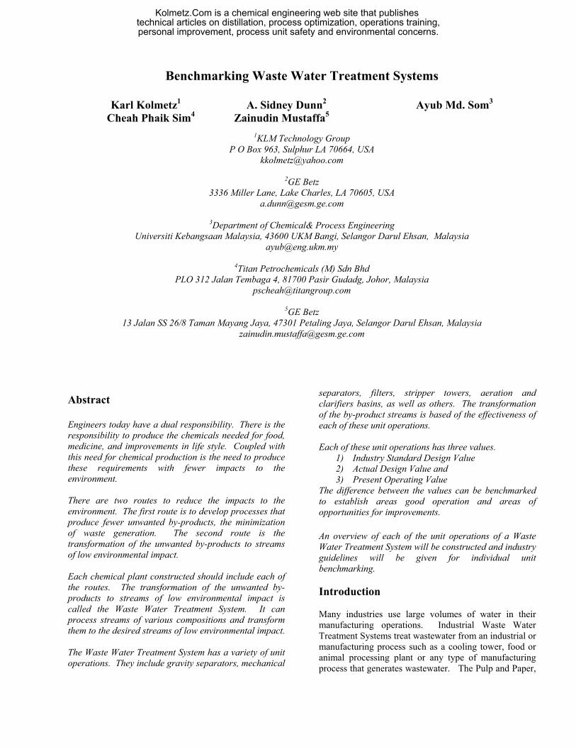
Figure 1- The Water Cycle The treatment process and equipment is specifically directed to control or remove certain organic or chemical compounds. The flow may or may not contain domestic wastewater and ranges from several hundred to several million GPD. Industrial applications can present challenges that are specific to the plant or process. Maintenance on these systems is always mandatory and contains specific performance parameters. The amount of organic material that can be discharged safely is defined by the effect of the material on the dissolved oxygen level in the water. Organisms in the water use the organic matter as a food source. In a biochemical reaction, dissolved oxygen is consumed, as the end product of water and carbon dioxide are formed. Atmospheric oxygen can replenish the dissolved oxygen consumption to exceed this re-supply; the dissolved oxygen level drops, leading to the death of fish and other aquatic life. Under extreme conditions, when the dissolved oxygen concentration reaches zero, the water may turn black and produce odors. Organic compounds are normally measured as chemical oxygen demand (COD) and biochemical oxygen demand (BOD). Industrial Waste Water Considerations include;
1. Volume of daily flow 2. All biological and chemical characteristics of
the wastewater,
3. Including biodegradability, toxic material content and any material covered by specific environmental regulations
4. Regulations of the local health department and
federal or state Environmental Protection Agency MOIST AIR TO
CONTINENT
SUN
CONDENSATION
The Waste Water Treatment System can be broken down into distinct components. (2)
PRECIPITATION RAIN EVAPORATION
TRANSPIRATION PONDS & LAKES 1. Pretreatment Units
RIVERS 2. Primary Treatment SOIL 3. Secondary Treatment 4. Tertiary Treatment LAKE
5. Sludge Handing (thickening and denaturing) OCEAN 6. Sludge Disposal GROUNDWATER
Waste Water Treatment System Overview Pretreatment Units Sedimentation - Gravity Separation Sedimentation is the separation from water of suspended particles that are heavier than water by gravitational settling. The purpose of sedimentation is 1) clarification - to produce clean water, which can be used, recycled or further treated and 2) consolidation - to produce concentrated solids that can be more easily handled and treated. Most waste treatment system employ a gravity separation step for suspended particle or oil removal. The settling rate of a particle is defined in terms of “free” verses “hindered” settling. A free settling particle’s motion is not affected by that of other particles, the vessel’s wall, or turbulent currents. A particle has a hindered settling rate if there is any interference from these effects. (2)
Table 1 - Effect of Particle Size on Settling
Unit
Size (microns)
Time to fall 1 meter
Settling (m/h)
Gravel 10,000 1 sec 3600 Sand Course 1,000 10 sec 360 Sand Fine 100 125 sec 28 Silt 10 108 min 0.5 Bacteria 1 180 hr Colloidal matter 0.1 2 years Color Particles 0.001 200 years Gravity settling is employed primarily for removal of inorganic suspended solids, such as grit and sand. The equipment employed for gravity separation for waste
Kolmetz.Com is a chemical engineering web site that publishes technical articles on distillation, process optimization, operations training,personal improvement, process unit safety and environmental concerns.

treatment is normally either a rectangular basin with moving bottom scrapers for solids removal or a circular tank with a rotating bottom scraper. Rectangular tanks are normally sized to decrease horizontal fluid velocity to approximately 1 foot per minute. Their lengths are three to five time their width and their depths are three to eight feet. Circular clarifiers are ordinarily sized according to the surface area, because velocity must be reduced below the design particle’s terminal velocity. The typical design provides a rise rate of 600-800 gpd/ft2. API Separator When wastewater contains appreciable amount of hydrocarbons, removal of these contaminants become a problem. Oil is commonly lower in density than water; therefore, if it is not emulsified, it can be floated in a separate removal stage or in a dual-purpose vessel that allows sedimentation of solids.
For example, the refining industry uses a rectangular clarifier with a surface skimmer for oil and a bottom rake for solids as standard equipment. Stokes’ Law expresses the basic principle governing the separation of oil from water by gravity differential as follows: (4)
Where:
υp = particle settling velocity g = acceleration due to gravity, 9.81 m/s2 ρp = density of particle ρw = density of water dp = diameter of particle µ = dynamic viscosity
Primary Treatment – Flotation Air Flotation Where the density differential is not sufficient to separate oil and oil-wetted solids, air flotation may be used to enhance oil removal. In this method, air bubbles are attached to the contaminant particles and thus the apparent density difference between the particles is increased. Dissolved air flotation (DAF) is a method of introducing air to a side stream or recycle stream at elevated pressures in order to create a super saturated stream. When this stream is introduced into the waste stream, the
pressure is reduced to atmospheric, and the air is release as small bubbles. These bubbles attach to contaminants in the waste, decreasing their effective density and aiding in their separation. The most important operation parameters for contaminate removal by dissolved air flotation are; (1) • Air pressure • Recycle or slip stream flow rate • Influent total suspended solids (TSS) including oil
and grease • Bubble size • Dispersion As in gravity settling, air flotation units are designed for a surface-loading rate that is a function of the waste flow and rise velocity of the contaminants floated by air bubbles. The retention time is a function of the tank depth. DAF units can be rectangular in design by are usually circular, resembling a primary clarifier or thickener. They are often single stage units. Induced Air Flotation (IAF) is another method of decreasing particle density by attaching air bubbles to the particles, however the method of generating the air bubble differs. A mechanical action is employed to create the air bubbles and their contact with the waste contaminants. The most common methods use high-speed agitators or recycle a slipstream through venturi nozzles to entrain air into the wastewater.
( )ρρυ2
pwp dg −= µ18p
In contrast to DAF units, IAF units are usually rectangular and incorporate four or more air flotation stages in series. The retention time per stage is significantly less that in DAF circular tanks. As in gravity settling, the diameter of the particle plays an important role in separation. Polyelectrolytes may be used to increase effective particle diameters. Polymers are also used to destabilize oil / water emulsions, there by allowing the free oil to be separated from the water. Polymers do this by charge neutralization, which destabilizes an oil globule surface and allows it to contact other oil globules and air bubbles. Emulsion breakers, surfactants, or surface-active agents are also used in air flotation to destabilize emulsions and increase the effectiveness of the air bubbles. Filtration Filtration is employed in waste treatment whenever suspended solids must be removed. In practice, filtration is most often used to polish wastewater following
Kolmetz.Com is a chemical engineering web site that publishes technical articles on distillation, process optimization, operations training,personal improvement, process unit safety and environmental concerns.
treatment. In primary waste treatment, filters are often employed to remove oil and suspended solids prior to biological treatment. More commonly, filters are used following biological treatment prior to final discharge or reuse. Filtration is also widely used as a tertiary treatment for suspended solids removal. The fundamental requirement is that the suspended particles are of sufficient size or capable of being increased in size by flocculation. In cases when it is not possible to flocculate such particles, more advanced techniques such as ultra-filtration is more practical. Some of the advantages of filtration are as follows: (3)
1. Simple to operate and easy to control 2. Can be used for almost any type of free-flowing
liquid stream containing suspended solid particles
3. Relatively cost competitive with regard to sludge dewatering processes
4. Lower energy consumption as compared to others
5. Can be integrated easily with other treatment trains
6. Great potential for recovery as the process will not chemically change the characteristics of the materials treated.
Some of the disadvantages, among others are: (3)
1. Not capable of producing a high purity effluent as both the liquid product and dewatered sludge still contain a certain fraction of the liquid and solid phase
2. Not capable of separating chemical components especially when they are present in the same phase.
3. Not capable of destroying or chemically changing the toxicity of materials
4. Will produce a liquid waste stream that requires further treatment prior to disposal.
Ultra-filtration Ultra-filtration, by definition, is a membrane filtration process that separates high molecular weight solutes or colloids from a solution or suspension. The process has successfully been applied to both homogeneous solutions and colloidal suspensions that are difficult to separate practically by other techniques. The types of membrane used for ultra-filtration are similar to reverse osmosis membranes that are made of cellulose acetate and nylon. It has demonstrated unique
capabilities in the treatment of industrial wastewaters such as the separation of oil from water, reduction of toxic compounds present in the wastewater and recovery of valuable byproducts. Nevertheless, the process is unattractive to small-scale industries due to high operating and capital costs. (3) Secondary Treatment - clarification The Secondary Treatment consists of at least two types of systems. The first is Fixed Film / Media System and the second is Suspended Growth Systems. The Fixed Film / Media Biological Oxidation System has a media in which the Biological Film is attached to a Media. The Waste Water is slowly passed through the Media and the Biological Film degrades the organics to non-organic products. The fixed film system include Trickling filters, Rotating Biological Contactor (RBC), etc. The Suspended Growth Biological Oxidation System includes Stabilization Ponds, Single Pass Aerated Lagoons and Activated Sludge Systems Biological Oxidation One of the most common ways to convert soluble organic matter to insoluble matter is through biological oxidation. Soluble organics metabolized by bacteria are converted to carbon dioxide and bacterial floc, which can be settled from solution. The biodegradable contaminants in water are usually measured in terms of biochemical oxygen demand (BOD). BOD is actually a measure of the oxygen consumed by microorganisms as they assimilate organics. Bacteria metabolize oxygen along with certain nutrients and trace metals to from cellular matter, energy carbon dioxide, water and more bacteria. This process may be represented in the form of a chemical reaction. (1)
Food (Organic compounds
+Microorganisms +Oxygen
+Nutrients
→
Cellular matte +Microorganisms +Carbon dioxide
+Water +Energy
The purity of the water depends on minimizing the amount of organic compounds that remain after secondary treatment. Factors that affect biological oxidation are shown in Table 2. (1)
Kolmetz.Com is a chemical engineering web site that publishes technical articles on distillation, process optimization, operations training,personal improvement, process unit safety and environmental concerns.
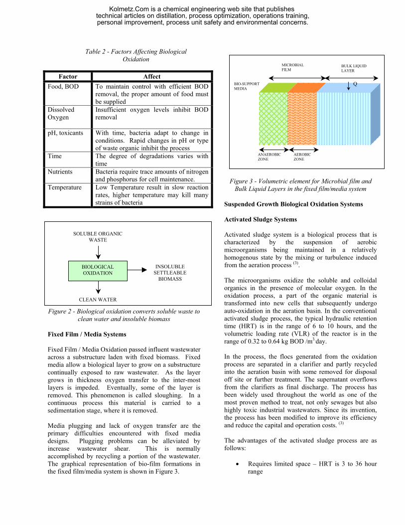
Table 2 - Factors Affecting Biological Oxidation
Factor Affect
Food, BOD To maintain control with efficient BOD removal, the proper amount of food must be supplied
Dissolved Oxygen
Insufficient oxygen levels inhibit BOD removal
pH, toxicants With time, bacteria adapt to change in conditions. Rapid changes in pH or type of waste organic inhibit the process
Time
The degree of degradations varies with time
Nutrients Bacteria require trace amounts of nitrogen and phosphorus for cell maintenance.
Temperature Low Temperature result in slow reaction rates, higher temperature may kill many strains of bacteria
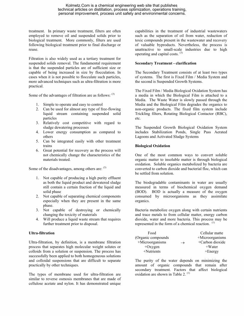
Figure 2 - Biological oxidation converts soluble waste to
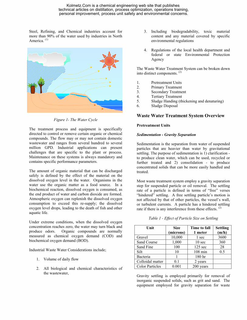
clean water and insoluble biomass Fixed Film / Media Systems Fixed Film / Media Oxidation passed influent wastewater across a substructure laden with fixed biomass. Fixed media allow a biological layer to grow on a substructure continually exposed to raw wastewater. As the layer grows in thickness oxygen transfer to the inter-most layers is impeded. Eventually, some of the layer is removed. This phenomenon is called sloughing. In a continuous process this material is carried to a sedimentation stage, where it is removed. Media plugging and lack of oxygen transfer are the primary difficulties encountered with fixed media designs. Plugging problems can be alleviated by increase wastewater shear. This is normally accomplished by recycling a portion of the wastewater. The graphical representation of bio-film formations in the fixed film/media system is shown in Figure 3.
MICROBIAL
FILM BULK LIQUID LAYER
QBIO-SUPPORT
MEDIA
ANAEROBIC ZONE
AEROBIC ZONE
Figure 3 - Volumetric element for Microbial film and Bulk Liquid Layers in the fixed film/media system
Suspended Growth Biological Oxidation Systems Activated Sludge Systems Activated sludge system is a biological process that is characterized by the suspension of aerobic microorganisms being maintained in a relatively homogenous state by the mixing or turbulence induced from the aeration process (3). The microorganisms oxidize the soluble and colloidal organics in the presence of molecular oxygen. In the oxidation process, a part of the organic material is transformed into new cells that subsequently undergo auto-oxidation in the aeration basin. In the conventional activated sludge process, the typical hydraulic retention time (HRT) is in the range of 6 to 10 hours, and the volumetric loading rate (VLR) of the reactor is in the range of 0.32 to 0.64 kg BOD /m3.day. In the process, the flocs generated from the oxidation process are separated in a clarifier and partly recycled into the aeration basin with some removed for disposal off site or further treatment. The supernatant overflows from the clarifiers as final discharge. The process has been widely used throughout the world as one of the most proven method to treat, not only sewages but also highly toxic industrial wastewaters. Since its invention, the process has been modified to improve its efficiency and reduce the capital and operation costs. (3) The advantages of the activated sludge process are as follows:
• Requires limited space – HRT is 3 to 36 hour range
CLEAN WATER
SOLUBLE ORGANIC WASTE
INSOLUBLE SETTLEABLE
BIOMASS
BIOLOGICAL OXIDATION
Kolmetz.Com is a chemical engineering web site that publishes technical articles on distillation, process optimization, operations training,personal improvement, process unit safety and environmental concerns.

• MLSS is in the range of 1500 to 10,000 mg/l • Reliable operator control capability • Can handle shock loads better with less
recovery time required • Can handle high loaded waste streams • Excellent solids removal capability
The disadvantages, among others, are as follows:
• Requires highly trained operators • Requires substantial monitoring • Requires high operation and maintenance costs • Sensitive to toxic discharges or load
fluctuations • Generates waste sludge products that are
difficult to dewater The control of contaminate oxidation at high BOD loading requires a bacteria population that is equal to the level of food. The need is the basis for the activated sludge process. In the activated sludge process, reactants, food, and microorganism are mixed in a controlled environment to optimize BOD removal. The process incorporates the return of concentrated microorganisms to the influent waste. When bacteria are separated from wastewater leaving an aeration basin and reintroduced to the influent, they continue to thrive. The re-circulated bacteria continue to oxide wastewater contaminates, and if present in sufficient quaintly, produce a relatively low BOD effluent water. Because the activated sludge process incorporates the return of concentrated microorganisms, it must include a process for microorganism concentration and removal. This process includes an aeration stage and a sedimentation stage.
Figure 4 - Activated sludge process returns active biomass to enhance waste removal
The operating parameters that affect the performance of any activated sludge process are BOD, microorganism, dissolved oxygen, retention time, nutrient concentration, and external influences of temperature and pH. In order
to understand the various activated sludge designs, it is necessary to examine the relationship between available food and bacteria population. Initially, excess food is present; therefore the bacteria reproduce in a geometric fashion. This is termed the “log growth phase”. As the population increase and food decrease a plateau is reached in population. From the inflection point on the curve to the plateau, population is increasing but a decreasing rate. This is called the “declining growth phase”. LOG
GROWTH DECLINING GROWTH
ENDOGENOUS
FOOD
REMAINING (BOD)
BACTERIA CONVENTIONAL
HIGH RATE
EXTENDED
AERATION DISPENSED GROWTH
Figure 5 - Model of bacteria population as a function of
time and amount of food Once the plateau is crossed, the bacteria are actively competing for the remaining food. The bacteria begin to metabolize stored materials, and the population decreases. This area of the curve is termed “endogenous respirations”. Eventually, the bacterial population and the DOD are at a minimum. Because activated sludge is a continuous, steady sate process, each plant operates at some specific point on the curve, as determined by the oxidation time provided. The point of operation determines the remaining bacteria population and BOD of the effluent.
AERATION INFLUENT CLARIFIER EFFLUENT
Optimization of an activated sludge plant requires the integration of mechanical, operational and chemical approaches for the most practical overall program. Mechanical problems can include excessive hydraulic loading, insufficient aerations, and short-circuiting. Operational problems may include spill and shock loads, pH shocks, failure to maintain correct mixed liquor concentrations, and excessive sludge retention in the clarifier. Because activated sludge depends on microorganism re-circulation, sedimentation is the key stage. The settle ability of the biomass is a crucial factor. As bacteria multiply and generate colonies, they excrete natural biopolymers. These polymers and the slime layer
WASTE EXCESS SLUDGE
RETURN SLUDGE
Kolmetz.Com is a chemical engineering web site that publishes technical articles on distillation, process optimization, operations training,personal improvement, process unit safety and environmental concerns.

that encapsulates the bacteria influence the flocculation and settling characteristics of the bacteria colonies. It has been determined empirically that the natural settle ability of bacteria colonies is also a function of their position on the time chart. Newly formed colonies in the log growth phase are relatively non-settle able. At the end of the declining growth phase and the first part of the endogenous phase, natural flocculation is at an optimum. As the endogenous phase continues, colonies break up and floc particles are dispersed, decreasing the biomass settle ability. Although microbes are eventually able to break down most complex organics and can tolerate very poor environments, they are very intolerant of sudden change is pH, dissolved oxygen and the organic compounds that normally upset and activated sludge system. These upsets normally result in poor BOD removal and excessive carry over of suspended solids (unsettled microorganisms) in the final effluent. Types Of Activated Sludge Systems (4)
1. Conventional, plug flow systems
The most common activated sludge design used by municipalities and industry operates in the endogenous phase, in order to produce and acceptable effluent in BOD and TTS levels. Conventional aeration represents a “middle of the road” approach because its capital and operating cost are higher than those of the high rate process, but lower than those of the extended aeration plants. Natural flocculation is at the optimum, so the required sedimentation time for the removal of suspended solids from the effluent is minimized. (1) Settled wastewater and return activate sludge (RAS) enter the front end of the aeration tank and are mixed by diffused air or mechanical aeration. In early designs, air application was generally uniformed throughout the tank length; however, low DO concentrations usually occurred in the initial passes of the tank. In modern designs, the aeration system is designed to match the oxygen demand along the length of tank by tapering the aeration rates. During the aeration period, adsorption, flocculation, and oxidation of organic matter occur. Activated sludge solids are separated in a secondary settling tank. (4)
2. Extended Aeration, plug flow systems
Extended aeration plants operate in the endogenous phase, but use longer periods of oxidation to reduce effluent BOD levels. This necessitates higher capital and operating cost (i.e., larger basins and more air). In conjunction with lower BOD, extended aeration produces a relatively high-suspended solids effluent when optimum natural settling ranges are exceeded. Extended aeration design may be necessary to meet effluent BOD requirements when the influent is relatively concentrated in BOD or the waste are difficult to biodegrade. Because extended aeration operates on the declining side of the biomass population curve, net production of excess solids is minimized. Therefore, savings in sludge handling and disposal cost may offset the higher pant capital and operating cost required for extended aeration. (1) The extended aeration process is similar to the conventional plug-flow process except that is operates in the endogenous respiration phase of the growth curve, which requires a low organic loading and long aeration time. Because of the long HRT (in the order of 24 to 36 hours), aeration equipment design is controlled by mixing needs and not oxygen demand. The process is used extensively for pre- engineered plants for small communities. Generally, primary clarification is not used. Secondary clarifiers are designed at lower hydraulic loading rates than conventional activated sludge clarifiers to better handle large flow rate variations of small communities. Although the bio-solids are well stabilized, additional bio-solids stabilization is required to permit beneficial reuse. (4)
3. Complete Mix Systems The complete mix activated sludge (CMAS) is an application of the flow regime of a continuous flow stirred-tank reactor. Settled wastewater and RAS are introduced typically at several points in the aeration tank. The organic load, MLSS concentration and oxygen demand are uniform throughout the tank. An advantage of the CMAS is the dilution of shock loads that occurs in the treatment of industrial wastewaters. The CMAS is relatively simple to operate but tends to have low organic substrate concentrations that encourage the growth of filamentous bacteria, causing sludge bulking problems.
Kolmetz.Com is a chemical engineering web site that publishes technical articles on distillation, process optimization, operations training,personal improvement, process unit safety and environmental concerns.

Table 3 - Activated Sludge Systems (1)
Process
Aeration Retention Time, hrs
MLSS, ppm DO ppm
Sludge Recycle %
BOD Loading Lb/mft3
F/M Lb BOD /
lb MLVSS
Sludge Production
BOD Removal
%
High Rate
0.5-3 300 - 1000 0.5-2 5- 15 2.5 1.5 – 5.0 0.65 – 0.85 75-85
Conventional
6 – 8 (diffused)
9-12 (mechanical)
1000 – 3000 0.5-2.0
20-30 20-40 0.2-0.5 0.35-0.55 85-90
Extended Aeration
18-35 3000 - 6000 0.5-2.0 75-100 10-25 0.03-0.15 0.15-0.20 90-95
Step Aeration 3-5 2000 - 3500 0.5-2.0 25-75 40-60 0.2-0.5 0.35-0.55 85-95 Contact
Stabilization 3-6 1000 -3000
(aeration) 4000–10000
(contact basin)
0.5-2.0 25-100 60-70 0.2-0.6 0.35-0.55 85-95
Pure Oxygen
1-3 3000-8000 2-6 25-50 100-250 0.25-1.0 0.35-0.55 95-98
Complete Mix
3-5 3000-6000 0.5-2.0 25-100 50-120 0.2-0.6 0.35-0.55 85-95
4. Contact Stabilization
Due to the highly efficient absorptive capabilities of activated biomass, the time necessary for biomass to capture the colloidal and soluble BOD is approximately 30 minutes to one hour. Oxidation of fresh food requires the normal aeration time of 4-8 hours. IN the contact stabilization design, relatively quick sorption time reduces aeration tank volume requirements. The influent waste is mixed with return biomass in the initial aeration tank (or contact tank) for 30-90 minutes. The entire flow goes to sedimentation, where the biomass and its captured organics are separated and returned to a re-aeration tank. In the re-aeration tank the wastes under go metabolism at a high biomass population. The system is designed to reduce tank volume by containing the large majority of flow for a short period of time. This process is not generally as efficient in BOD removal as the conventional plant process, due to mixing limitation in the contact basin. Operating costs are equivalent. Due to the un-stabilized state of the biomass at sedimentation, flocculation is inferior. Suspended solids in the effluent are problematic. Because this design exposed only a portion of the active biomass to the raw effluent at a time, it is less susceptible to feed variations and
toxicants. For this reason it can be beneficial for treatment of industrial wastes. (1) The contact zone detention time is relatively short (30 to 60 minutes), and the MLSS concentration is lower than in the stabilization zone. Rapid removal of soluble BOD occurs in the contact zone, and colloidal and particulate organics are captured in the activated sludge floc for degradation later in the stabilization zone. In the stabilization zone, RAS is aerated and the detention time is in the order of 1 to 2 hours to maintain a sufficient SRT (solids retention time) for sludge stabilization. Because the MLSS concentration is so much higher in the stabilization zone, the contact stabilization process requires so much less aeration volume than CMAS or conventional plug flow process for the same SRT. The process was developed for BOD removal and the short contact time limits the amount of soluble BOD degraded and NH4-N oxidation. (4)
5. Step Feed
In a plug flow basin, the head of the basin receives the waste in its most concentrated form. Therefore, metabolism and oxygen demand are greatest at that point. As the waste proceeds thought the basin, the rate of oxygen
Kolmetz.Com is a chemical engineering web site that publishes technical articles on distillation, process optimization, operations training,personal improvement, process unit safety and environmental concerns.

uptake (respiration rate) decreases, reflecting the advanced stage of oxidation. Tapered aeration and step aeration reduce this inherent disadvantage. Tapered aeration provides more oxygen at the head of the basin and slowly reduces oxygen supply to match demand as waste flows through the basin. This results in better control of the oxidation process and reduced air cost. Step aeration modifies the introduction of influent waste. The basin is divided into several stages, and raw influent is introduced to each stage proportionally. All return microorganisms (sludge) are introduced at the head of the basin. This design reduces aeration time to 3-5 hours, while BOD removal efficiency is maintained. The shorter aeration time reduces capital expenses because a small basin can be used. Operating costs are similar to those of a conventional plant. (1)
Flexibility of the operation is one of the important features of this process because the apportionment of the wastewater feed can be changed to suit operating conditions. The concentration of MLSS may be as high as 5000 to 9000 mg/l in the first pass, with lower concentrations in subsequent passes as more influent feed is added. This process has the capability of carrying a higher solids inventory and thus a higher SRT for the same volume as a conventional plug flow process. (4)
6. Oxidation Ditch
Oxidation ditch consists of a ring or oval-shaped channel equipped with mechanical aeration and mixing devices. Screened wastewater enters the channel and is combined with the RAS. The tank configuration and aeration and mixing devices promote unidirectional channel flow, so that the energy used for aeration is sufficient to provide mixing in a system with a relatively long HRT. The aeration/mixing method used creates a velocity from 0.25 – 0.30 m/s in the channel, which is sufficient to keep the activated sludge in suspension. At these channel velocities, the mixed liquor completes a tank circulation in 5 –15 minutes, and the magnitude of the channel flow is such that it can dilute the influent wastewater by a factor of 20-30. As a result, the process kinetics approach that of a CMAS, but with pug flow along the channel.
7. High -Purity Oxygen
A staged enclosed reactor is used in the high-purity oxygen. Three or four stages are generally used and the influent wastewater, RAS and high-purity oxygen are added to the first stage. The oxygen partial pressure in the headspace may range from 40 to 60 percent in the first stage to 20 percent in the last stage. At high oxygen partial pressure, higher volumetric oxygen transfer rates are possible so that pure oxygen systems can have a higher MLSS concentration and operate at a shorter HRT and higher VLR than conventional processes. The rate of oxygen addition is 2 to 3 times greater than CAS. Major advantages for pure oxygen systems are the reduced quantities of off-gas if odor control and VOC control are required.
8. Sequential Batch Reactors (SBR)
The SBR is a fill-and-draw type of reactor system involving a single complete-mix reactor in which all steps of the activated sludge process occur. An SBR goes through a number of cycles per day; a typical cycle may consist: fill, aeration, settle and withdrawal of supernatant. An idle step may also be included to provide flexibility at high flows. Mixed liquor remains in the reactor during all cycles, thereby eliminating the need for separate secondary clarifiers. The HRT ranges from 18 to 30 hours, based on influent flow rate and tank volume used.
Latest Research in Wastewater Treatment Systems Recently, biological process has been attracting considerable attention for removing heavy metals from aqueous wastes. Biofilm systems, in particular, are able to retain relatively high biomass concentrations resulting in shorter liquid detention times, better performance stability and higher volumetric removal rates. The efficiency of an expanded bed biofilm reactor in the treatment of waste waters contaminated with heavy metals has been investigated for rubber product manufacturing industry. In the study, it has been found that the process could achieve 60% to 90% removal of Zinc. Application of plant-based flocculants can be considered as new in industrial wastewater treatments. Despite its biodegradable characteristics, plant-based flocculants
Kolmetz.Com is a chemical engineering web site that publishes technical articles on distillation, process optimization, operations training,personal improvement, process unit safety and environmental concerns.

possess an advantage for oxidation and coagulation process. A newly invented plant-based flocculants, namely KN2 has been introduced in the treatment of inking wastewater. Comparison has also been made with other conventional chemical-based flocculants (i.e. PAC, PE, PDMC, etc.) in order to compare their effectiveness in removing pollutants. Application of activated carbon as a polishing media at the final stage shows a drastic declination in COD and BOD values as well as the other parameters. Dissolved Air Flotation (DAF) using micro-bubbles of size 50µm are used to remove suspended solids, emulsified oils & greases from industrial and municipal waste waters. Micro-sized air bubbles are formed by injection of pressurised recycle water into a flotation tank using special designed nozzles or needle valves. These bubbles will attach to the suspended solids and float them to the surface. The floated sludge can be removed either by overflow or mechanical scraping. Influencing parameters being studied are bubble size, particle size, air pressure for saturated vessel, air saturation system, and efficiency of suspended solids removal. The saturation system consists of an unpacked saturation vessel, an air compressor and the associated control system. The saturation vessel operated at a 4 bars pressure. The results of the study have reported that percentage removal of Suspended Solids, COD, Colour and Turbidity were 90%, 91%, 86% and 90%, respectively. Simulation has been carried out to obtain kinetic data for the parameters under study.
Conclusions The Waste Water Treatment System has a variety of unit operations. They include gravity separators, mechanical separators, filters, stripper towers, aeration and clarifier basins, as well as others. The transformation of the by-product streams is based of the effectiveness of each of these unit operations. Each of these unit operations has three values.
4) Industry Standard Design Value 5) Actual Design Value and 6) Present Operating Value
The difference between the values can be benchmarked to establish areas good operation and areas of opportunities for improvements. A review of the individual unit operations should be conducted to maximize the effectiveness of a Waste Water Treatment System.
Kolmetz.Com is a chemical engineering web site that publishes technical articles on distillation, process optimization, operations training,personal improvement, process unit safety and environmental concerns.
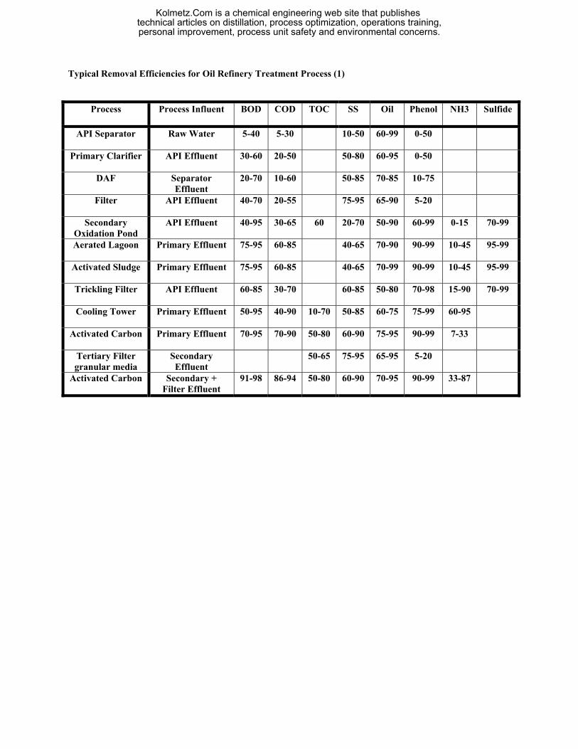
Typical Removal Efficiencies for Oil Refinery Treatment Process (1)
Process
Process Influent BOD COD TOC SS Oil Phenol NH3 Sulfide
API Separator
Raw Water 5-40 5-30 10-50 60-99 0-50
Primary Clarifier
API Effluent 30-60 20-50 50-80 60-95 0-50
DAF
Separator Effluent
20-70 10-60 50-85 70-85 10-75
Filter
API Effluent 40-70 20-55 75-95 65-90 5-20
Secondary Oxidation Pond
API Effluent 40-95 30-65 60 20-70 50-90 60-99 0-15 70-99
Aerated Lagoon
Primary Effluent 75-95 60-85 40-65 70-90 90-99 10-45 95-99
Activated Sludge
Primary Effluent 75-95 60-85 40-65 70-99 90-99 10-45 95-99
Trickling Filter
API Effluent 60-85 30-70 60-85 50-80 70-98 15-90 70-99
Cooling Tower
Primary Effluent 50-95 40-90 10-70 50-85 60-75 75-99 60-95
Activated Carbon
Primary Effluent 70-95 70-90 50-80 60-90 75-95 90-99 7-33
Tertiary Filter granular media
Secondary Effluent
50-65 75-95 65-95 5-20
Activated Carbon
Secondary + Filter Effluent
91-98 86-94 50-80 60-90 70-95 90-99 33-87
Kolmetz.Com is a chemical engineering web site that publishes technical articles on distillation, process optimization, operations training,personal improvement, process unit safety and environmental concerns.
References 1. Betz Handbook of Industrial Water Conditioning, Ninth Edition, 1991 2. Ondeo Nalco Water Treatment Technology Customer Seminar, Traders Hotel Singapore, May 2001 3. Ayub Md. Som, Department of Chemical & Process Engineering, Universiti Kebangsaan Malaysia, 43600 UKM
Bangi, Selangor Darul Ehsan, Malaysia 4. Wastewater Engineering, 4th. Edition, Metcalf & Eddy, 2003.
Kolmetz.Com is a chemical engineering web site that publishes technical articles on distillation, process optimization, operations training,personal improvement, process unit safety and environmental concerns.