volume 2 number 1 january 2016 - klmtechgroup.com
TRANSCRIPT

WWW.IACPE.COM
Design Guidelines for Safety in
Piping Networks
SPECIAL FEATURE
J A N U A R Y 2 0 1 6 V O L U M E 2 N U M B E R 1
P A G E 1
ABOUT
International Association of Certified Practicing Engineers provides a standard of pro-
fessional competence and ethics. Identifies and recognizes those individuals that have
meet the standard. And requires our members to participate in continuing education
programs for personal and professional development.
In additional to insuring a professional level of competency and ethics the IACPE fo-
cuses on three major areas of development for our members: Personal, Professional,
and Networking.
HISTORY
The International Association of ertified Practicing Engineers concept was ormulat-
ed by he any oung professionals and students e eet during our careers
working n the field, running training courses, and lecturing at universities.
During question and answer sessions we found the single most common question
was: What else can I do to further my career?
We found, depending on the persons avail able time and finances, and very often de-
pendent on the country in which the person was from, the options to further ones
career were not equal.
Many times we found the options available to our tudents in developing countries
oo costly and or provided too little of value in an expanding global business
The reality is that most of our founders come from countries that require rigor-
ous academic standards at four year universities in order to achieve an engineering
degree. Then, after obtaining this degree, they complete even stricter government
and state examinations to obtain their professional censes in order to join profes-
sional organizations. They have been fforded he opportunity o continue heir
personal and professional development with many affordable schools, programs, and
professional organizations. The IACPE did not see those same opportunities for every-
one in every country.
So we set out to design and build an association dedicated to supporting those engi-
neers in developing in emerging economies.
The IACPE took input from industry leaders, academic professors, and students
from Indonesia, Malaysia, and the Philippines. The goal was to build an organiza-
tion that would validate a candidates engineering fundamentals, prove their
individuals skills, and enhance their networking ability. We wanted to do this
in a way that was cost effective, time conscience, and utilized the latest technologies.
MISSION Based on engineering first principles and practical real world applications our curricu-
lum has been vetted by academic and industry professionals. Through rigorous study
and examination, candidates are able to prove their knowledge and experience. This
body of certified professionals engineers will become a network of industry profes-
sionals leading continuous improvement and education with improved ethics.
V O L U M E 2
N U M B E R 1
J A N U A R Y 2 0 1 6
ACADEMIC BOARD
Dr. Dominic Foo
Dr. Sivakumar
Kumaresan
Dr. Muaffaq A Yani
INDUSTRY BOARD
Helmilus Moesa
Supriyanto
Timothy M. Zygula
Lee Pheng
LEADERSHIP BOARD
Karl Kolmetz
William B. Lotz
Lin L. Choo
VISION
To become a globally recognized association for certification of professional engineers.
WWW.IACPE.COM | [email protected]
KNOWLEDGE. CERTIFICATION. NETWORKING

P A G E 2
LETTER FROM THE PRESIDENT
KARL KOLMETZ
Welcome to 2016 and new goals for the New Year. Or you may call these goals,
New Year's Resolutions. Most people’s resolutions revolve around making im-
provements in health, family life, finances and/or career.
The common thread among these resolutions is making good choices. Many peo-
ple learn how to make good choices through past bad choices (trial and error).
No one can go back to make a brand new start, but anyone can choose to move
forward from today and begin to construct a new future through good choices.
IACPE can help you focus on your career related resolutions, which in turn will
positively impact your health, family life and finances going forward. I know a great
way to move your career forward to a better and brighter future is joining IACPE.
The three key components of an IACPE education are Knowledge, Certification
and Networking. Each of these components will give you a well-rounded and
structured advanced education that will ultimately boost your career goals into the next desired phase.
If you or someone you know is entering a STEM college, researching or applying
to colleges, I ask that you consider attending a college that has partnered with
IACPE. The practical design knowledge that IACPE imparts will greatly assist in
your education and career.
All the Best in Career and Life,
Karl Kolmetz
New Year, New You


P A G E 4
INTRODUCTION TO REFINING by William B. Lotz
In November and December 2015 IACPE’s “Introduction to Refining” seminar conduct by IACPE
Vice President Mr. William B. Lotz was a resounding success given the feedback from students.
“Introduction to Refining” was held in November at Universitas 17 Agustus 1945 Semarang, Universitas
17 Agustus 1945 Surabaya, University Sanata Dharma Yogyakarta and Sekolah Tinggi Teknologi Fatahillah
Cilegon. Before the seminar held in Surabaya, IACPE met with the East Java Association of Engineering
and Consulting in hopes of forming a long-term relationship.
CAREER GUIDELINES by Karl Kolmetz
IACPE President Mr. Karl Kolmetz presented a “Career Guidelines” seminar at two universities. If
you are applying to a university, you should strongly consider those universities that have part-
nered with IACPE to help build your practical knowledge during your studies and certification for
your professional practice.
“Career Guidelines” was held at University Islam Kadiri, Kediri in November and Institute Technology
Indonesia in December.
IACPE is also honoured that an engineering design company has chosen to train their engineering staff
through IACPE. Give your employees the training they need for their engineering career and professional
life with IACPE.
NEWS

P A G E 5
INDUSTRY NEWS India Approves HPCL’s Visakh Refinery Expansion
State-run Hindustan Petroleum Corp. Ltd. (HPCL) received environmental clearance
from Indian officials to expand its Visakhapatnam refinery in Andhra Pradesh from 8.33
MMtpy to 15.0 MMtpy, reports said this week.
India's Expert Appraisal Committee (EAC), under the Ministry of Environment and For-
ests, approved the 18,400-crore expansion plan which was earlier rejected in 2013, citing a moratorium
on industrial expansion in some of parts of Visakhapatnam.
"The Committee deliberated upon the issues raised during the public hearing/public consultation meeting
conducted by the AP Pollution Control Board on June 26, 2015," the EAC said in the minutes of the
meeting.
"The issues were raised regarding CSR, accident in plant premises, impact on environment in terms of
traffic pollution, wages for contract workers, local employment and water supply facilities.
Shell Contracts Wood Group for Prelude FLNG Work in Australia
Wood Group has secured a three-year contract with Shell Australia’s Prelude floating
liquefied natural
gas (FLNG) project, officials confirmed on Wednesday. Perth-based Wood Group Kenny
will provide specialist consultancy services for flexible riser integrity management prior
to and during operation of Prelude FLNG, which will be located 475 kilometers north-
north east of Broome in Western Australia.
The focus of the contract will be the development and implementation of the flexible riser integrity man-
agement plan, as well as inspection, monitoring, testing and on call engineering support. This contract, ef-
fective immediately, follows Wood Group Kenny’s successful design of Prelude’s subsea flowlines.
Honeywell to Automate, Supply Vietnam’s PV Gas with Modular LPG Plant
Honeywell announced this week that it will supply a 250 million standard cubic feet/day
(mmscfd) modular gas processing plant and advanced automation systems to PetroVi-
etnam subsidiary, PV Gas. PV Gas, Vietnam’s primary gas provider, will use Honeywell
UOP’s modular gas processing plant to separate liquefied petroleum gas (LPG) from nat-
ural gas at its Ca Mau facility near the southern tip of Vietnam.
Honeywell Process Solutions (HPS) will serve as the integrated main automation con-
tractor (I-MAC) and supply the integrated controls and safety systems for the facility and
terminal. PV Gas’s total capital investment for the project is approximately $498 million.
PV Gas supplies natural gas to generate nearly 40% of the nation's electricity, and local production ac-
counts for more than 55% of Vietnam’s domestic demand for LPG.
CB&I Announces Polypropylene Technology Award in China
CB&I today announced it has been awarded a contract by Hebei Haiwei Group for the
license and basic
engineering design of a polypropylene unit to be built in Jingxian, Hebei Province, China.
The unit will use CB&I's Novolen® technology to produce 200,000 metric tons per an-
num of polypropylene. CB&I previously announced the license and engineering design of
a propane dehydrogenation unit, which uses CB&I's CATOFIN® technology, at the
same location.
"CB&I is pleased to have been selected as the polypropylene licensor for the project," said Daniel McCar-
thy, President of CB&I's Technology operating group. "This award builds on our relationship with Hebei
Haiwei as it follows the successful development of the CATOFIN propane dehydrogenation unit."

DESIGN GUIDELINES FOR SAFETY IN PIPING NETWORKS
By: Karl Kolmetz, KLM Technology Group Stephen J.Wallace, Wallace Consulting Services
Mee Shee Tiong, KLM Technology Group
Introduction
When compared to other equipment in a hydrocarbon
processing plant, the piping network is designed to the
most stringent standards. Mechanical Engineering codes
require a 400% safety factor in the design of these sys-
tems. The piping system is normally considered the
safest part of the plant. However, even with this level
of safety, reviews of catastrophic accidents show that
piping system failures represent that largest percentage
of equipment failures (1).
Since these systems are responsible for many cata-
strophic accidents, operations, design, and maintenance
personnel should understand the potential safety con-
cerns. The best tool that we have to prevent future
accidents is to review past incidents and incorporate
lessons learned into future design and operation of pip-
ing systems.
This paper will discuss various case studies that will
help to illustrate the consequences of inappropriate
design, operation, and maintenance of piping systems.
The case studies include 1) Check valve failures; 2)
Small bore piping in compressor discharge piping, 3)
Low temperature embitterment, and 4) Hot tapping
safety issues and hot tap shavings concerns.
P A G E 6


Check Valve Failures
Check valves are important safety devices in piping. Check
valves have been utilized in the process industry for many
years to keep material from flowing the wrong way and
causing operational or safety concerns. One common mis-
take is installing the check valve backwards and blocking
the process flow. There is normally an arrow on the check
valve designating the proper flow direction, indicating the
proper installation position. There have been cases where
the manufacturer showed the arrow incorrectly, which
greatly hindered troubleshooting.
Case 1 - In December 1991, a chemical plant in Saudi Ara-
bia (2) experienced a release of propane gas due to a check
valve shaft blowout. The incident followed a process upset
in the facility's ethylene plant, where the inadvertent shut-
down of a cracked gas compressor resulted in downstream
flow instabilities and initiated a 13 hour period of surging in
the unit's propane refrigeration compressor.
During this period, the check valves installed in the pro-
pane refrigeration compression system slammed closed
repeatedly. The shaft of the compressor's third stage dis-
charge valve eventually separated from its disk and was
partially ejected from the valve. The shaft was not fully
ejected because its path was blocked by an adjacent steam
line inches away from the valve, keeping about 70 mm of
the shaft's length within the valve body.
Propane gas began to leak out of the valve around the gap
between the shaft and its stuffing box until operators dis-
covered the leak and shut down the compressor. Opera-
tors also discovered that the valve's drive shaft counter-
weights had broken off of the drive shaft and had been pro-
pelled approximately 16 meters (45 feet) from the valve.
The facility was fortunate that an adjacent steam line kept
the shaft from being fully ejected from the valve, thus limit-
ing the leak rate and preventing an accident of potentially
greater severity. It was also fortunate that no one was
struck by the counterweights when they were propelled
from the valve.
A subsequent investigation and analysis of the check valve's
internal components revealed that the dowel pin, which
secured the drive shaft to the valve flapper, had sheared,
and the shaft key had fallen out of its key-way. The investi-
gation report also revealed that facility maintenance rec-
ords indicated a long history of problems with the check
valves installed there. The valves were installed in 1982,
and due to continuing valve malfunctions, underwent repair
or modification in 1984, 1986, 1987, 1989, and 1990. These
repairs and modifications included replacement of damaged
counterweight arms, replacement of seals and gaskets, re-
placement of dowel pins and internal keys, and installation
of external shaft "keepers".
Case 2 – An incident with a similar failure mechanism oc-
curred in an Ethylene Plant in Texas in June 1997 (2). The
check valve was on the process gas compressor discharge
line, which had high flow, high pressure and high tempera-
ture, along with compressor vibration; however, the inves-
tigation team found no evidence that these temperature
and pressure limits were exceeded at any time prior to or
during the accident. The check valve was installed on the
fifth stage of the compressor and had an internal diameter
of 36 inches and weighed 3.2 tons. The valve had a design
limit pressure of 480 psig, and a design limit temperature of
115 degrees F.
The drive shaft penetrates the pressure boundary through
a stuffing box. The exterior portion of the drive shaft is
connected to the pneumatic piston and counterweight, and
the interior portion of the shaft is coupled directly to the
valve disk using a cylindrical hardened steel dowel pin and a
steel rectangular bar key. This arrangement provides a
counter weight to partially balance the weight of the valve
disk, and provides the pneumatic power assist to maintain
the valve closed as described above.
This check valve was the same design as the previous check
valve and had the same failure mechanism. The pneumatic
assist assembly became unattached from the check valve,
leading to loss of hydrocarbon containment and a major
unit fire. The unit was down for several weeks for repair.
This fire resulted in minor process operator injuries, public
road closures, and property damage both within the olefin
unit and to off site business. The EPA and OSHA under-
took an investigation of this accident because of its severi-
ty, its effects on the public, and "the desire to identify those
root causes and contributing factors of the event that may
have broad applicability to industry, and the potential to
develop recommendations and lessons learned to prevent
future accidents of this type".
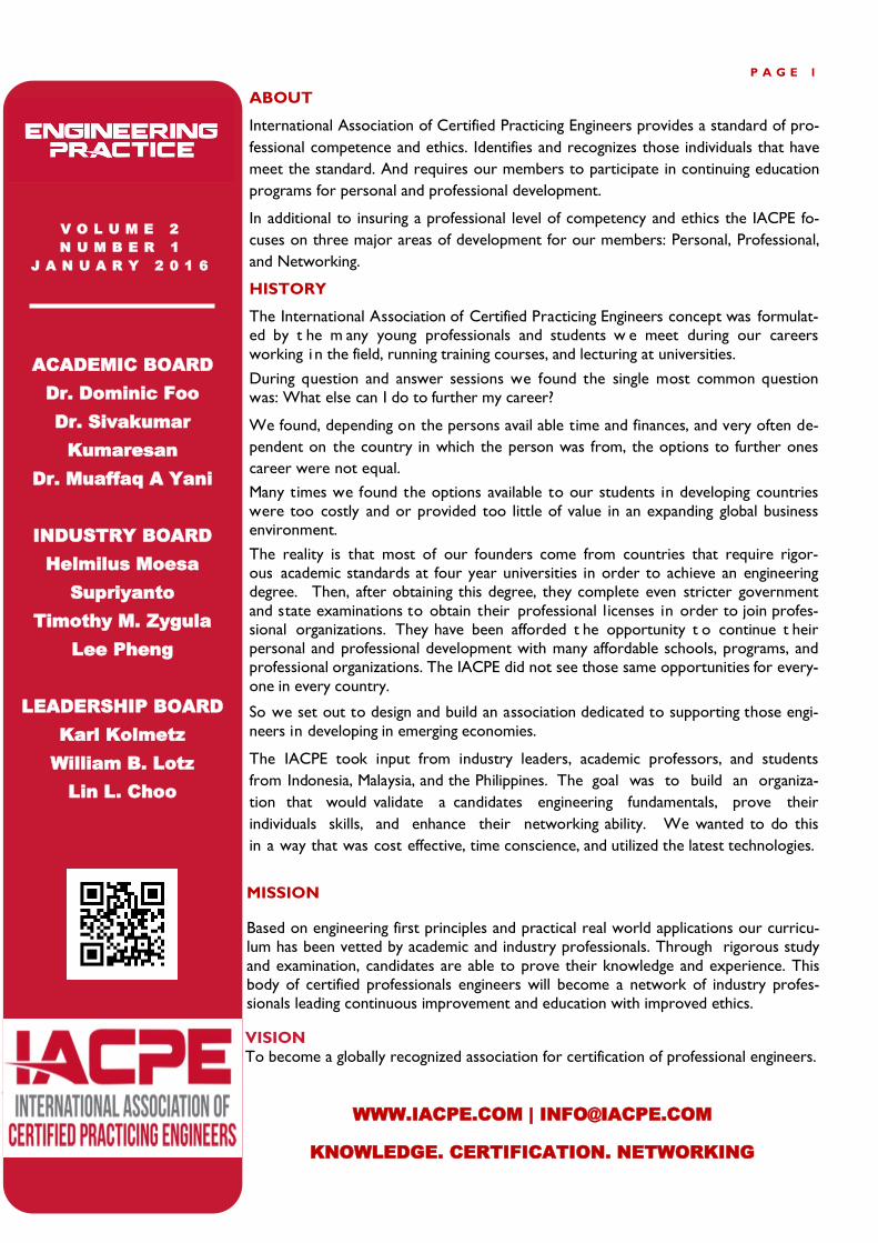
Case 3 - An Ethylene Plant in Louisiana had a near miss
from a check valve failure in 1999. The check valve had an
external bull plug, which allowed the check valve swing pin
to be installed. The bull plug slowly rotated out over time
leading to loss of hydrocarbon containment on a medium
pressure ethane feed line. The line was isolated, copious
amounts of water were applied to the leak, and fortunately
the vapor did not find a source of ignition.
P A G E 8
This check valve was far away from a source of vibration
such as a compressor. The root cause of the incident is
was not totally identified but one theory is that normal
piping vibration caused the bull plug to rotate. The Eth-
ylene plant reviewed all check valves in hydrocarbon ser-
vice and installed an anti rotation locking device to pre-
vent the bull plugs from rotating and causing a loss of
hydrocarbon containment.
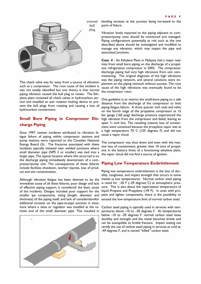
Small Bore Piping in Compressor Dis-
charge Piping Since 1997, sixteen incidents attributed to vibration fa-
tigue failure of piping within compressor stations and
pump stations were reported to the Canadian National
Energy Board (3). The fractures associated with these
incidents typically initiated near welded junctions where
small diameter pipe (NPS 2 or smaller) was tied into a
larger pipe. The typical location where this occurred is on
the discharge piping immediately downstream of a com-
pressor/pump unit. The consequences of these failures
include facilities shutdown, worker injuries, loss of prod-
uct and site contamination.
Although vibration fatigue has been deemed to be the
immediate cause of all these failures, poor design and lack
of effective piping support is considered the basic cause
of the incidents. Designs included poor support for the
smaller ipe components, sizing (length, diameter and
thickness) of the piping itself, and lack of considerationfor
additional stresses on the pipe-to-pipe junction in situa-
tions where a valve or regulator was installed at the re-
mote end of the small diameter pipe. This resulted in
bending stresses at the junction being increased to the
point of failure.
Vibration levels imparted to the piping adjacent to com-
pressor/pump units should be monitored and managed.
Piping configurations potentially at risk such as the one
described above should be investigated and modified to
manage any vibration, which may impact the pipe and
associated junctions.
Case 4 - An Ethylene Plant in Malaysia had a major near
miss from small bore piping on the discharge of a propyl-
ene refrigeration compressor in 2002. The compressor
discharge piping had very high vibrations from unit com-
missioning. The original diagnosis of the high vibrations
was the piping network, and several solutions were im-
plement on the piping network without success. The root
cause of the high vibrations was eventually found to be
the compressor rotor.
One guideline is to restrict the small-bore piping to a safe
distance from the discharge of the compressor to limit
piping fatigue failure. A three quarter inch stub and valve
on the fourth stage of the propylene compressor at 15
bar gauge (160 psig) discharge pressure experienced the
high vibration from the compressor and failed, leaving an
open ¾ inch line. The resulting massive loss of contain-
ment went unnoticed because the propylene vapor was at
a high temperature 70 C (155 degrees F) and did not
cause a vapor cloud.
The compressor was shut down and even with the mas-
sive loss of containment, greater than 10 tons of propyl-
ene in the battery limits of a functioning ethylene plant,
the vapor cloud did not find a source of ignition.
Piping Low Temperature Embrittlement Piping low temperature embrittlement is the loss of duc-
tility, toughness, and impact strength that occurs in some
metals at low temperatures. Normal carbon steel piping
is rated for -20 F (–29 degrees C) at atmospheric pres-
sure. This is also about the vaporization temperature of
liquid Propane and Propylene (-49 F). In units with pro-
pane and lighter components, there is the possibility to
exceed the low temperature limit of normal carbon steel.
Carbon steel piping is typically used in services with tem-
peratures above -10 to –20 degrees F. At temperatures
below -10 to -20 degrees F. normal carbon steel loses
ductility and strength and the metal becomes brittle and
can be susceptible to brittle fracture. Impact testing can
certify the use of carbon steel piping in services as cold as
-49 degrees F, and is named “killed” carbon steel.
P A G E 9
external
bull
plug

Partners to the Top Summit Technology Management is a technical consultancy group, providing specialized
services and training to improve process plant operational efficiency, profitability and safety. We
provide engineering solutions by offering training, technical services, best practices, and equip-
ment to meet the specific needs of our partner clients.
Basic Design Packages
Detailed Design Packages
Commissioning of Process Units
Process Engineering Studies
Bench Marking of Process Units
Regional Training Conferences & In
-House Training
Singapore & Malaysia Company
Registration & Set Up
Specialty Equipment: Distillation
Equipment, Filter Skid Packages,
Compressor Knockout/Scrubber
Skid Packages, Mercury Removal
Skid Packages
www.summit-tech-mtg.com

P A G E 1 1
John A. Reid (4) put together list of ethylene plant hy-
drocarbon incidents. He noted four incidents where
low temperature embrittlement cause line failures. Cas-
es he noted included:
1. 1965 Explosion and Fire Due to Cold Brittle
Flare Line Fracture at PCI Olefin Unit in Lake
Charles, La.
2. 1966 Flare System Explosion - Monsanto's
Chocolate Bayou Olefin Unit
3. 1975 DePropanizer - Explosion in a Naphtha
Cracking Unit – Dutch State Mines – 14 fatali
ties
4. 1989 Cold Brittle Line Fracture Results in
Gas Leak, Explosion and Fire at Quantum's
Morris Illinois Ethane/Propane Cracker – two
fatalities
Case 5 - An incident occurred in January 2002 at an
Ethylene plant in Louisiana. The Ethylene Plant pub-
lished the incident in the AIChE Ethylene Producers
Conference in 2004 (5) and in a conference in Asia in
2002 (6) to increase safety awareness in the process
industry.
The plant was Olefins Ethane Cracker with a flow
scheme of the DeMethanizer first and a back end acety-
lene converter. An off-spec event on 1/4/02 at the acet-
ylene converter led to flaring of ethylene product via the
unit cold flare drum. Through a sequence of events, the
cold flare drum overhead line fell to below its minimum
design metallurgy temperature. On 1/5/02, the cold
temperatures led to brittle fracture of the cold flare
drum overhead line, loss of hydrocarbon containment,
and ultimately an explosion and fire.
The cold flare drum contents are vaporized and super-
heated with a closed loop propanol system. Heat is sup-
plied to the propanol system with 70-pound steam,
which is about 270 F. The vaporizer and super heater
heats the cold flare drum material from cryogenic tem-
peratures to above the minimum design metal tempera-
ture of the cold flare drum carbon steel overhead piping.
The event sequence was the ethylene product went off
specification on acetylene and initiating flaring of liquid
ethylene product began. The acetylene converter outlet
analyzer was in error, which allowed the ethylene split-
ter inventory to be contaminated with acetylene prior
to corrective action being taken. A portion of the off
spec liquid ethylene product was consumed by internal
customers, with the balance being flared via the cold
flare drum. Malfunction of the cold flare drum vaporizer
and super heater allowed the cold flare drum overhead
line temperature to fall sharply.
A low temperature alarm sounded as the overhead flare
line temperature fell to 0 F, and the thermocouple went
bad at a value of -13 F. With the cold flare drum over-
head line running below its minimum design tempera-
ture of -10 F, the pipe ruptured, resulting in loss of hy-
drocarbon containment. The hydrocarbon released
found an ignition source, resulting in an explosion and
fire.
The root causes of the incident included the vaporizer
and super heater exchanger fouling, which had reduced
heat transfer capacity of the cold flare system. Once
flaring began, the cold flare drum overhead line experi-
enced low temperature resulting in the brittle fracture
of cold flare drum overhead piping due to operation
below the minimum design temperature of the carbon
steel line.
The final stress that ultimately caused the brittle fracture
of the piping has not been identified, but could have
been any number of internal or external stresses. 1)
External stress - Hard rain that came at the time of
event, 2) Internal stress - Contraction of the cold flare
line due to temperature gradient.
Cold
flare
drum
Warm
flare
drum
Super-
heater
Pipe
rupture
Fi
re

The incident causes an explosion and damage to equip-
ment, but no first aid or recordable incidents to personnel.
As a result of the incident the ethylene plant upgraded
many carbon steel systems to stainless steel, which has a
lower temperature limit.
Hot Tapping Safely and Process Concerns Hot Tapping is used in plant maintenance activities to obtain
access to a pressurized line or vessel. Hot tapping involves weld-
ing on a piece of equipment, typically a spool piece to which a
valve is then connected. The types of equipment include pipe-
lines, vessels or tanks that contain steam, natural gas or flamma-ble liquids under pressure, in order to install additional connec-
tions to reroute or to block the flow in a line. It is commonly
used to replace or add sections of pipeline without the interrup-
tion of service for air, gas, water, steam and petrochemical distri-
bution systems. The hot tap process is utilized to install a new
working valve or to control the de-pressuring of the equipment.
During the hot tap process a drill bit assembly is connect-
ed to the new spool piece and a new working valve. The
new valve is attached to the line and the drill assembly is
installed and the hole drilled. The bit is retracted past the
valve, which can then be closed. A flow or line can then
be fitted into the valve. The American Petroleum Institute
has guidelines for precautions to take during hot taps.
One of the main concerns of hot tapping is the metal shav-
ings, which are produced by either drilling or cutting.
Some of the metal shavings will enter into the process and
could be carried downstream and cause problems by en-
tering pumps or strainers. Therefore, careful planning must
be made to determine if the metal shavings will cause a
problem down stream.
During the initial planning of the hot tap one aspect to
look at would be to tap from the bottom, which would
give you the best chance of retaining most of the metal
shavings. However, there is also a concern about shavings
entering the seat of the valve. The rule of thumb would be
never tap at 5 o’clock or 7 o’clock as shavings could get
into the seat and keep the valve from closing.
Case 6 - An olefins producer in Louisiana had two eth-
ylene plants that shared a single flare area. The two steam
lines to the flares were at one point only 100 feet apart.
Whenever a unit upset occurs, steam is utilized in the flare
tip to mix the hydrocarbons with air for complete com-
bustion. This mixing reduces the flare smoking and envi-
ronmental damage from carbon monoxide.
At times during unit upsets there can be a shortage of
steam. This shortage can lead to additional flaring at the
very time you need steam to reduce the smoking flare.
Therefore, to address this scenario, the ethylene producer
decided to connect the two flare steam lines together.
When one unit was having operational problems, the adja-
cent unit could provide steam to the flare and potentially
have the first unit recover faster while reducing overall
flaring, with the additional economic benefit of being able
to produce on specification product faster. The two adja-
cent steam lines were hot tapped and a line installed to
connect the two new hot tap valves.
At the next unit upset the line was utilized to reduce the
overall flaring and optimize unit production. Unfortunate-
ly, some metal shavings were left in the steam lines. These
metal shavings were carried to the flare steam ring and
blocked a portion of the steam ring above the steam line
connection to the steam ring.
The steam ring no longer had uniform steam distribution
as a portion of the ring was blocked by the hot tap metal
shavings. This was not fully known until the next major
unit outage when the flare tip was upgraded to reduce the
smoking. Due to the mal-distribution of the steam the
flare now smoked constantly, even at low flaring scenarios.
The producer was then fined for the continuously smoking
flare.
Guidelines These six case studies provide many incites into piping
safety concerns. Petroleum plant personnel should review
these case studies and consider implementing the guide-
lines where applicable for increased safety.
1. Check Valve Installations:
Review large and small check valve installations
for potential release scenarios. For large high-
pressure check valves review the internals and
the sited case study failure mechanism. Install anti
rotation devices on external bull plugs.
2. Small Bore Piping on Compressor Discharge
Piping:
Review and reduce small-bore piping on compres-
sor discharge piping. One guideline is to restrict
the small-bore piping to a safe distance from the
discharge of the compressor to limit piping fatigue
failure.
Vibration levels imparted to the piping adjacent to
compressor / pump units should be monitored
and managed. Piping configurations potentially at
risk should be investigated and modified to man-
age any vibration, which may impact the pipe and
associated junctions.
P A G E 1 2

3. Low Temperature Embrittlement Concerns:
Understand piping low temperature embrittlement
concerns and potential release scenarios. There
have been multiple piping failures and hydrocarbon
releases from piping low temperature embrittlement.
Review the process temperatures and the piping
metallurgies where the temperatures are below –49
F, which is approximately liquid propane / propylene.
4. Safety Perform Hot Taps:
When making a hot tap, certain steps should be
followed prior to starting the actual tap. The
following steps consist of basic procedures used
in completing the hot top installation;
A) Perform a site visit, to determine if the job
safety analysis information meets the proper
criteria for that particular hot tapping oper-
ation.
B) Recognize and identify the hazards of the
equipment, then outline steps to mitigate
those hazards into a job safety sheet.
C) Review the job and file a basic safety plan.
D) The proposed hot tap area should be
marked on the piping network.
E) Minimize the piping network pressure to
the practical operations limit.
F) A plan for isolating the piping network
should be prepared for an emergency.
Conclusions
Piping network safety is a concern for all hydrocarbon
producers even though piping may be the considered the
safest part of the plant. The authors goals and hopes are
that these case studies and guidelines provide additional
safety incite into piping design, operation and prevention
of future incidents.
P A G E 1 3
PT. Dinamika Teknik Persada
is an Engineering Consultants focused on providing engineering and technical services to the oil and gas industry. We develop innovative and cost effective solutions and helping our clients to achieve high performance from their assets by providing expertise, novel methods and appropri-ate tools -FEED to Detailed engineering Design -Independent Design Verification -Risk Assessments -Asset Integrity Management -Risk Based Inspection -Reliability Centered Maintenance -Fitness for service Assessment -Remaining Life Assessment -Finite Element Analysis
PT Dinamika Teknik Persada provide Engineering Design to the upstream and down-stream sectors of oil & gas industry: - Processing plants - Pressure vessels - Heat exchangers - Piping systems - Onshore pipelines - Offshore pipelines - Offshore platforms - Drilling rigs
Address : Ruko Golden Boulevard Blok K No. 1-2 Jl. Pahlawan Seribu, BSD City, Serpong
Tangerang 15322 – Indonesia Phone / Fax : +62 21 53150601
Email : [email protected] Website: www.dtp-eng.com

References
1. Chemical Processing Safety: Fundamentals with
Applications; Crowl and Louvar; Prentice-Hall;
1990
2. EPA/OSHA Joint Chemical Accident Investiga
tion Report of the Shell
Chemical Company's Deer Park, Texas Olefin
Complex Fire of June 22, 1997.
EPA Document 550-R-98-005
3. Canadian National Energy Board Safety Adviso
ry, File 3750-A000-8
3 December 2003
4. Ethylene Plant Safety Incidents, John A Reid,
unpublished
5. Kuo A., Pitt R, “Flare Line Failure Case, What
Have We Learned”, 16th Annual Ethylene Prod
ucers. Conference Session T8001, Ethylene
Plant Safety, New Orleans, LA, April 25-29,
2004
6 Tarkiz Ruslan, Tham Chee Mun, Karl Kolmetz,
“Flare Safety Overview”, 7th Regional Olefin
Committee Technical Conference, Kerteh,
Malaysia, 16-18 September 2002
Looking for cleaning supplies, industry cleaning chemicals, odour control products, paint thinner solvents, white spirit, industrial laundry chemi-cals, chaffing fuel, and laundry detergent sup-plies in Kuwait? Al Sanea Chemical Products has the best chemical products' supply for all your needs. Al Sanea Chemical Products Sabhan Industrial Area, Street No. 84, Block No.8, Plot No. 185, Kuwait (P.O. Box 5629, Safat 13057, Kuwait) Tel: 00965 – 24747623 / 24734991 / 24734952/ 24736740 Fax: 00965 - 24760678 Email: [email protected] Web: www.alsanea.com
P A G E 1 4
IACPE………………………………….Page 3
KLM Technology Group………………Page 7
Summit Technology Management……..Page 10
PT. Dinamika Teknik Persada…………Page 13
Al Sanea Chemical Products…………..Page 14
Advertisers

P A G E 1 5
BIODATA
KARL K. KOLMETZ
Over twenty five years of progressive experience in the
design, construction, commissioning, and operations
management of process units from the US Gulf Coast to
Alaska through Asia. Strengths encompass design details
that originate from a strong operations background, with
the ability to incorporate positive ideas from differing
sources.
Publications include authoring and co-authoring over 40
technical papers on a variety of subjects for product re-
covery, distillation troubleshooting, training, project man-
agement, and process design with safety and environmen-
tal concerns. Papers have appeared in Oil and Gas Jour-
nal (5), Hydrocarbon Processing (1), Chemical Engineer-
ing Progress (1) and Hydrocarbon Engineering (1). Con-
ference papers have been presented at the AIChE Con-
ferences, the Indian Oil & Gas Conference, the Japan
Petroleum Institute Refining Conference, Oil and Fats
International Congress, Best Practices in Process Plant
Management, and the Asean Regional Olefins Confer-
ences, as well as others.
In 2004 He was the Distillation Editor of the Asia Pacific
Journal of Chemical Engineering and is currently author-
ing a book on process equipment design. The book has
32 chapters on a variety of subjects including, Pumps,
Distillation Columns, Process Control, LPG, LNG and
LPG. He has a Bachelor of Science in Chemical Engineer-
ing from The University of Houston. He is a member of
the American Institute of Chemical Engineers and Inter-
national Association of Certified Practicing Engineers. He
has been asked to serve as an industrial advisor to a
board helping set the Chemical Engineering Curriculum
in Malaysia.
STEPHEN J.WALLACE
Has over 20 years of technical experience in the design,
construction, commissioning and operations management
of process units located in the Continental United States
and South East Asia. He has a strong background in the
manufacturing of a wide variety of chemical process tech-
nologies and product categories including; cryogenic liq-
uids, ethylene, propylene, benzene and toluene extrac-
tion, styrene, polyurethane, polymers and steam & power
plant operations.
Mr.Wallace has an established track record in the field of
process safety. He possesses extensive experience per-
forming hazard analyses using a variety of techniques,
operating experiences as a production manager, process
safety consultant and manager of safety and health, and
author of over 25 presentations and publications in the
field of safety and loss prevention.
Stephen has a Bachelor of Science in Chemical Engineer-
ing from The University of Kentucky. He is registered
Professional Engineer (by exam) in the field of Chemical
Engineering. He is certified by the board of Certified
Safety Professionals (BCSP) as a certified Safety Profes-
sionals.
TIONG MEE SHEE
Has over 15 years experiences, has bachelor degree of
chemical engineering from Universiti Malaysia Sabah. Shee
currently Manager R&D/Process Chemist at Ken-Rich
Chemical Production Sdn.Bhd.

Www.iacpe.com