beech 18 document · pdf file · 2012-07-01beech 18 document this beech 18 document...
TRANSCRIPT

BEECH 18 DOCUMENT
This Beech 18 Document applies to all Beech 18 series airplanes including military counterparts and other counterparts approved by Supplemental Type Certificates (STC’s), regardless of the category or categories of airworthiness certification. COMPLIANCE: Required as indicated. To prevent possible failure of wing structure, accomplish the following for the left and for the right sides of each affected airplane.
A. Prior to the next flight after October 1, 1980, all Beech 18 series airplanes were required to
incorporate kits to reinforce the wing spars using an approved STC. Eligible strap installations are SA643CE with SA1206CE, SA832SW with SA895SW, SA1581SW with SA1582SW, SA2000WE, SA962EA, SA814SO, SA1533WE with SA2737WE, SA1192WE with SA3229WE, SA3009WE, SA3010WE, SA3021WE, and any future STC approved for this purpose.
B. Conduct repetitive inspections of the wing structure and strap components at times which
do not exceed intervals 1,000* Flight Hours or 48 months, whichever occurs first, since the last inspection. If the last inspections occurred during compliance of AD 75-27-09 R2, no additional inspections are required until the next interval time as stated; i.e., within 1,000 Flight Hours or 48 months of the last inspection.
*Upon operator’s request, FAA Maintenance Inspector may extend this interval (or the interval specified below) by not more than 100 hours to permit compliance at an inspection period established for the operator.
1. Temporarily remove the spar reinforcement kit and inspect strap components for corrosion, fretting, cracking, and other defects in accordance with the applicable STC holder’s instructions, if the STC holder is no longer in existence or supporting the STC, as follows:
STC HOLDER PREVIOUS
STC HOLDER NAME (as noted in AD 75-27-09 R2)
STC NUMBERS
APPLICABLE AIRCRAFT SPECIFICATION NOS.
INSTRUCTIONS
Vintage Aircraft Attn: Mr. Taigh Ramey, 7432 C.E. Dixon Street, Stockton, CA 95206
Aerospace Products, Inc.
SA3009WE, SA1192WE with SA 3229WE SA3010WE with SA3021WE
A-765 A-765 A-765 A-757 A-2-582
Number 1869, dated May 1980
Aviation Fabricators, 805 N Fourth Street, Clinton, MO 64735
Airline Training, Inc.
SA814SO
A-684, A-757, A-765
Section 7, Document 7312, dated August 1974
1

Avidesign Attn: Mr. Mark Ward, 375 Durley Avenue, Camarillo, CA 93010
Canadian Aerocon, Ltd
SA962WE (Note: This STC is the only one listed that is approved for floats)
630, 710, A-2-582, A-684, A-757, A-765
Maintenance Manual Supplement, dated July 1973
Sierra Industries, Inc., 122 Howard Langford Drive, Uvalde, TX 78801
The Dee Howard Company
SA832SW, SA895SW SA1581SW with SA1582SW
A-765 A-765 A-2-582 A-2-582
Rev. A, Service Bulletin SB 18-2, dated July 1980
Southwestern Aero Exchange, Inc., Attn: Mr. David Warren, 18502 E 108th Street N, Owasso, OK 74055
Hamilton Aviation
SA2000WE A-757, A-765 Document D4-74. dated July 1974
Mr. Ray M. Jourdan, 11001E. 59th Street, Raytown, MO 64133
Jourdan Aircraft
SA643CE with SA1206CE
A-2-582, A-757, A-765
Service Bulletin SB 18-1, dated July 1980
Staggerwing Museum Foundation, Inc., P.O. Box 550, Tullahoma, TN 37388
The Dee Howard Company
SA1533WE with SA2737WE
A-765 A-765
Rev. A, Service Bulletin SB 18-2, dated July 1980
2. Inspect the front spar of the wing center section and outer wing panel at sites and by methods specified below.
Wing Station (WS)
Site* Method** Reference Figures
12 and 20 Exterior portion of lower spar tube in center section for corrosion
Visual, X-ray Figure 1 (Sheet 1) Figure 3 Figure 4 (Sheet 2)
12 and 20 Interior portion of lower spar tube in center section for internal corrosion
X-ray Figure 1 (Sheet 1) Figure 3 Figure 4 (Sheet 2)
32 Tips of welds at wing splice plate, fore and aft surfaces of tube
Visual, X-ray and wet magnetic particle
Figure 1 (Sheet 1) Figure 3 Figure 4 (Sheets 3 & 4)
2

43 to 45 Tip of weld around
cluster upper surface of the lower spar tube
Visual and wet magnetic particle
Figure 1 (Sheet 1) Figure 3 Figure 4 (Sheet 5)
46 Outboard ends of the fishmouth splice in lower spar tube, upper and lower surface of the lower spar tube
Visual, X-ray and wet magnetic particle
Figure 1 (Sheet 1) Figure 3 Figure 4 (Sheet 5)
57, 64, 73, and 81 Tips of welds at gussets on the upper surface of the lower spar tube
Visual, X-ray and wet magnetic particle
Figure 1 (Sheet 1) Figure 3 Figure 4 (Sheets 6 & 9)
60 and 62 Tips of welds as shown in Figure 4 (Sheet 7 and 8)
X-ray Figure 1 (Sheet 1) Figure 3 Figure 4 (Sheets 7 & 8)
61 Lower surface of lower spar tube below tube cluster, as seen from wheel well
Visual and wet magnetic particle
Figure 1 (Sheet 1) Figure 3
90 Tips of welds at clevis tangs on the lower spar tube, upper and lower surface
Visual, X-ray and wet magnetic particle
Figure 1 (Sheet 1) Figure 3 Figure 4 (Sheet 12)
90U Interior of the upper spar tube at clevis tangs for internal corrosion
X-ray Figure 1 (Sheet 1) Figure 3 Figure 4 (Sheet 11)
102 Tips of welds as shown in Figure 4 (Sheet 11) and Figure 1 (Sheet 1)
X-ray Figure 3 Figure 5 (Sheets 1 & 2)
111 Tips of welds as shown in Figure 4 (Sheet 11) and Figure 1 (Sheet 1)
X-ray Figure 3 Figure 5 (Sheets 3 & 4)
NOTES: *90U is in upper spar tube of center section. All other sites are
in lower spar tube. WS 57 and 64 need not be separately X-rayed if these sites are shown by WS 60 and 62 radiographs. Refer to figures of this document for more detailed information.
** A tube (not isotope) source is required for X-raying unless otherwise requested and authorized under paragraph F, below
3. Temporarily remove the spar tube reinforcement straps, inspection access covers
and other equipment as necessary to eliminate interference with required inspections. Also, drain inboard fuel tanks prior to X-ray of WS 60 and 62 sites.
3

4. Temporarily or permanently install metallic tape, wire or “hose” clamps squarely
around the spar tube (existing clamps, etc., may be used) as necessary to provide two X-ray beam alignment indicators near WS 32, 73, and 81 sites, and near WS 57 and 64 sites if the latter are to be separately X-rayed. Each indicator must be no more than one inch from the nearest inspection site, no more than two inches from the companion indicator, and perceptible in the related radiograph.
5. Taking only one radiograph at a time, accomplish X-ray inspection in accordance
with ASTM E1742 and the following instructions:
(a) Use ASTM E1742 approved penetrameters of sizes specified by figures of this document except at WS 90U and 60/62 sites where no penetrameter is required. Secure penetrameters to source-side surface of the spar tube, except film-side placement is permitted at WS 102 and 111 sites if access does not allow source-side placement.
(b) At each site, use GAF 800, DuPont NDT-65, Kodak AA, or equivalent film, sandwiched between lead screens of 0.005-inch thickness. Additionally, at WS 60, 62, and 111 sites, use a second film in multi-film technique that provides film speed ratio of Kodak M/Kodak AA. With each film pack, use small identification symbols for at least the site (e.g., LWS 81, RWS 90U, LWS 60A, etc.), date, and airplane registration number. Position each film pack close to the site, using figures of this document for guidance.
NOTE: It is advisable to secure a “back-up” lead plate of 0.12-inch thickness at all sites, especially where film is beneath the spar tube.
(c) Ascertain that the X-ray source is secured against the upper wing skin for
WS 60 and 62 sites and approximately 36 inches from the film at all other sites, at chordwise and spanwise angles specified by Figure 3 of this document.
(d) Ascertain that neither the airplane nor the source will be moved by wind or other influences, and expose the film so as to obtain 1.5 to 2.8 radiographic density near inspection sites specified in Figures 4 and 5 of this document. Use the same kinds of film and exposure time for WS 62 sites as for WS 60 sites.
(e) Retake any radiograph which evidences unsharpness, missed or obscured site, improper density, improper beam alignment, or in which at least two penetrameter holes are not perceptible.
NOTE: Beam alignment indicators are either structural features such as top and bottom tangs, or indicators specially installed such as hose clamps and metallic tape.
4

6. Using a low power magnifying device, examine each radiograph under viewing
conditions that show penetrameter holes. Look for evidence of corrosion pitting and transverse cracking in unwelded spar tube material. Pay particular attention to unwelded spar tube material adjacent to features such as screw holes, corrosion pits, and tips and edges of welds. Submit a report to maintenance facility accomplishing the requirements of this document showing the location of each indication of cracking and corrosion pitting in spar tube material. Use FAA Advisory Circular AC 43-4A, “Corrosion Control for Aircraft” as a guide for classification of corrosion.
7. After sites are thoroughly cleaned of any oil, grease, exhaust residues, or other surface contamination, inspect by visual and ASTM E1444 magnetic particle methods, using materials and procedures as specified below. Inspect for cracking, external corrosion pitting, and holes through spar tubes. Pay particular attention to locations specified by the X-ray report. Guidance may be found in FAA Advisory Circular AC 43.13-1B, “Acceptable Methods, Techniques, and Practices – Aircraft Inspection and Repair.”
(a) Conduct visual inspection using a flashlight or other illumination and low
power magnifying device. (b) Conduct a wet fluorescent magnetic particle inspection in accordance with
ASTM E1444. Utilize the procedures presented in the magnetic particle section of the “Nondestructive Inspection (NDI) Evaluation Checklist” that can be obtained by request from the FAA or from the following Internet Website: http://www.faa.gov/avr/afs/300/checklis.doc .
8. Keep all radiographs at an accessible location apart from the airplane as long as
the airplane is in service. C. Corrosion damage must be classified as light, moderate, or severe in accordance with
definitions in FAA Advisory Circular AC 43-4A, “Corrosion Control for Aircraft”. Consult a qualified structures Designated Engineering Representative (DER) for acceptance/approval of areas found to have corrosion.
D. Obtain (unless previously done) and follow the cognizant (aircraft or strap, as appropriate)
manufacturer’s or qualified structures DER’s instructions for repair and/or continued service of each defect that is found during inspections required by this document. If continued service with corroded wing structure has been previously authorized, field comparison of old and new radiographs must show that no subsequent deterioration has occurred, or remaining strength must be re-evaluated by the aircraft manufacturer or a qualified DER. Contact RAC Customer Support for old radiographs.
NOTE: In the context used above, old radiographs are legacy radiographs (X-rays) from previous inspection(s) of the subject aircraft’s wing structure.
5

E. Alternative methods of compliance with this document must be approved by the Manager,
Wichita Aircraft Certification Office, 1801 Airport Road, Room 100, Wichita, Kansas 67209, telephone (316) 946-4106, FAX 316-946-4107.
F. Non-Destructive Inspections (NDI) must be accomplished by a Non-Destructive Inspection
(NDI) inspector qualified and certified in the radiographic (X-ray) and Magnetic Particle methods of inspection to a Level II or Level III in accordance with the AIA Specification NAS-410 (MIL-STD-410) for the NDI inspections covered in this document. Operators outside of the United States must use equivalent specifications.
G. The authorized person performing any X-ray inspection required by this document shall, in
addition to the information required by FAR 43.9 and 91.173, list the date of the letter of authorization under which he performed said inspection in the aircraft maintenance records specified in FAR 91.713(a)(2).
H. In addition to the requirements presented in Paragraphs A through G above, airplanes with
VOLPAR tri-gear and conventional gear require inspections and corrosion treatment of the interior of the lower spar tube in accordance with the following sub-paragraphs:
(a) VOLPAR (TRI-GEAR) AIRCRAFT – STCs SA111WE AND SA4-1531 (These two STCs are issued to Cameron & Stahl, Inc. STC Holder’s address is Aerospace Products, 5523 Satsuma Avenue, North Hollywood, CA 91601.)
1. Remove two bolts from each attach point of the Volpar truss to Beech spar truss assembly, one at the lowest point and one at the highest point of attachment. (See Figures 6 and 7.) Blow warm air (max 300°F) for a period of 30 minutes through each tube with an air nozzle applied at the upper bolt hole.
NOTE: Drive screws located at a point lower than the lowermost bolt hole should also be removed. Proceed per Paragraph H. (a) 2.
Remove the two AN3-17A bolts, if Volpar Service Bulletin 14 has not been accomplished, from the lower elliptical spar tube and the 299-2 drag strut at the point just inboard of the outer wing attach fitting. (See Figure 8)
Inspect the bolts for indications of corrosion and pitting and the edge of the bolt hole through the elliptical spar tube for indications of moisture and/or corrosion.
NOTE: If greater than .005 deep pitting is indicated by this inspection, proceed per the inspection evaluation required in Paragraph H. (a) 3. before continuing.
Remove the drive screw from the elliptical spar tube at a point just outboard of the side of the fuselage. Blow warm air (max 300°F) through the elliptical spar tube by introducing the air at the bolt hole in the spar tube in one nacelle and out at the other nacelle. Proceed per Paragraph H. (a) 2.
2. Seal all remaining bolts and attach points with Pro Seal Compound 890, or
equivalent. Flush all spar truss tubes affected with MIL-C-16173, Grade 2
6

preservative, or equivalent and improve the seal as needed. Drain oil from all tubes. Replace drive screws previously removed.
NOTE: Use care when filling tubes, as spillage during filling and draining may cause preservative to flow throughout the wing and fuselage. It is suggested that waste material be used to absorb surplus preservative at the lower end of –277 tube, that is open.
Replace all bolts and nuts removed and seal with Pro Seal 890 sealing compound per view Figures 6 and 7. Remove waste material from –277 tube.
NOTE: Pro Seal 890 sealing compound is available from PRC-Desoto International. Other MIL-S-8802, Class B sealants such as PR-1440 or equivalent sealing compounds to Pro Seal 890 may be used.
Do not replace the AN3-17A bolt removed from the lower spar tube, and the 299-2 drag strut at inboard of the outer wing attach point. After flushing with preservative, plug the No. 10 hole in the spar tube top and bottom sides with an AN3-15A bolt and AN365-1032 nut. Seal each bolt and nut with Pro Seal 890 or equivalent sealing compound. See Figure 8 for details. Modify the 299-2 Drag Strut by cutting off the lug for the bolt. Install the Volpar 873 strap installation and 873-2 strap.
3. Indication of corrosion at the lower spar tube is evaluated in this document. 4. Complete the modifications specified in Paragraphs H. (a) 1. and H. (a) 2.
NOTE: All reference in Paragraph H. (a) was made concerning the left side of the aircraft spar truss. The inspection also applies to the right side spar assembly and must be repeated.
(b) CONVENTIONAL GEAR AIRCRAFT
THE FOLLOWING PROCEDURES ARE AN ALTERNATE METHOD TO PARAGRAPH H. (a) 1., WHEN REMOVAL OF THE DRIVE SCREW AT THE ELLIPTICAL SPAR TUBE CANNOT BE ACCOMPLISHED.
NOTE: Aircraft with conventional landing gear spar tube access can be gained through the existing Linoil drain holes. These holes can be enlarged to a maximum diameter of 5/32”. In the upper spars, the drain holes are located in the upper surface. Where holes are not accessible, new holes of no larger the 5/32” can be drilled in the lower surface at each end of the center section upper spar tube. The hole must be at least ½” away from the end of a gusset or end of a wing attach forging weld.
Access to the outer panel lower spar tube can be obtained by first marking a ½” hole in the skin centered under the spar tube, near the inboard and outboard ends (Approx. WS 102 and 177), and then drilling the (5/32” max) holes in the spar tube. After the flushing processes are completed, these holes must be closed by
7
installing a blind rivet or drive screw. The blind rivet or drive screw must be sealed using Pro Seal Compound 890 or equivalent. The holes in the skin can be closed using a ½ flush plug (metal or synthetic material). Since removal of the drive screw at the elliptical spar tube cannot be accomplished to determine if the spar is free from entrapped moisture, the following procedure will be adhered to:
1. Inflate one main shock strut assembly to its maximum height. Deflate the opposite
shock strut assembly to its minimum height. 2. Place a suitable support stand below the tail skid at fuselage station 380. 3. Install aircraft main jack pads. Place one jack under the high side only. 4. Jack the high side of the aircraft up until the center line of the main wheel axle is
19.0 inches above the floor. This action positions the aircraft so that any entrapped moisture will flow through the spar tube towards the existing 3/16” bolt hole located in the outboard end of the spar tube in the nacelle area on the low side of the aircraft.
5. Allow sufficient time for any entrapped moisture to drain. 6. Blow warm air (max 300°F) for a period of 30 minutes through each tube with an
air nozzle applied at the upper bolt hole or linoil drain hole. 7. Flush all spar truss tubes affected with MIL-C-16173, Grade 2 preservative, or
equivalent and improve the seal as needed. Drain oil from all tubes.
NOTE: Use care when filling tubes, as spillage during filling and draining may cause preservative to flow throughout the wing and fuselage. Suggest use of waste material to absorb surplus preservative at lower end of elliptical spar tube that is open.
8. Complete the requirements of Paragraph H. (b) 1. through Paragraph H. (b) 7. on
the opposite side of the aircraft.
9. Service the main landing gear shock strut assemblies in accordance with the Volpar or Beech Model 18 Service Manuals. Remove jack pads.
Currently effective Raytheon Aircraft Corporation Service Bulletins 64-15, 64-16, 64-17, and
66-10 and Strap STC-Holder’s Publications consider this subject but this document takes precedence in any conflicting detail.
8

D270901.AI
NOTE - ON THE LEFT WING, THE WING ATTACH FITTINGS ARE WELDED TO THE SPAR TUBE SUCH THAT THE SHORT TANG IS WELDED AT THE UPPER, FORWARD LOCATION OF BOTH W.S. 90U AND W.S. 90L. ON THE RIGHT WING, THE WING ATTACH FITTINGS ARE WELDED TO THE SPAR TUBE SUCH THAT THE LONG TANG IS WELDED AT THE UPPER, FORWARD LOCATION OF BOTH W.S. 90U AND W.S. 90L. ON THE LOWER SPAR TUBE AT BOTH LOCATIONS OF BOTH WINGS, THE TANGS ARE OPPOSITE.
VIEW SHOWING LEFT WING MAIN SPAR CENTER SECTION (W.S. 0.0 - W.S. 94.00)( RIGHT - OPPOSITE)
A
B
C
D
W.S. 94
W.S. 90U
W.S. 90L
WING ATTACH
FITTINGS
*
*
*
W.S. 81*
W.S. 73*
W.S. 64*
W.S. 57*
W.S. 32*
W.S. 46* W.S.
43*
W.S. 20* W.S.
12*
W.S. 61 W.S.
44
W.S. 28
SPLICE PLATE
W.S. 77
INDICATES AREAS TO BE INSPECTED PER THIS A.D.
SLIDE TUBE CLUSTER
JACKPAD CLUSTER
FUSELAGE
Figure 1 (Sheet 1) – Locator View (Left Wing Spar Truss Shown, Right Typical)
9

Detail A - Typical Gusseted Joint
Detail B - Typical Cluster (Plain) Joint
Figure 1 (Sheet 2) – Typical Joints
10

Detail C –Typical Wing Fitting Weldment
Detail D - W.S. 32 Critical Inspection Areas of Reinforcement Plates
Figure 1 (Sheet 3) – Typical Wing Fitting and Reinforcement Plate Weldment
11

D270953.AI
FWD
EXISTING NUTPLATES RETAINED (8) PLACES INDICATED BY (+)
BRACEEXISTING CUTOUT
EXISTING DOUBLER, PER BEECH SERVICE BULLETIN 64-17
RIB 1 NOSE
LOWER WING SKIN
FIRST STRINGER FORWARD OF SPAR
INBOARD EDGE OF FILLER
NACELLE
FORWARD TANK BULKHEADJACKPAD
SPAR TUBE NEW CUTOUT
VIEW LOOKING DOWN ON LOWER WINGSKIN AND SPAR TUBE
Figure 2 – W.S. 46 Orientation Detail
12

D270954.AI
3"
Figure 3 Radiograph Film (X-Ray) Locations and Source Orientation/Aiming Angles
13

D270955.AI
A
G
B
C
F
H
I
E
D
J
VIEW SHOWING RIGHT WING MAIN SPAR CENTER SECTION (W.S. 0.0 - W.S. 94.00)( LEFT - OPPOSITE)
Locator View (Right Wing Spar Truss Shown, Left Typical) For Figure 4 (Sheets 2 through 12)
Figure 4 (Sheet 1) – Locator View
14

Detail A – Lower Spar Tube Corrosion Inspection at W.S. 12 and W.S. 20
Figure 4 (Sheet 2) – W.S. 12 and W.S. 20 Inspection Locations
15

Detail B – W.S. 28 Splice Plate and W.S. 32 Inspection Locations
Figure 4 (Sheet 3) – W.S. 28 Splice Plate and W.S. 32 Inspection Locations
16

D270959.AI
NOTE - POSITIVE IMAGE OF RADIOGRAPH IMAGE (X-RAY)
CLAMP FOR ALIGNMENT/ORIENTATION
Radiograph Images for W.S. 32 Spar Tube with Non-reinforced Splice Plate
D270965.AI
NOTE - POSITIVE IMAGE OF RADIOGRAPH IMAGE (X-RAY)
CLAMP FOR ALIGNMENT/ORIENTATION
Radiograph Images for W.S. 32 Spar Tube with Reinforced Splice Plate
Figure 4 (Sheet 4) – Typical Radiographic Images at W.S. 32 (Detail B)
17

Detail C – W.S. 46 Inspection Location
D270957.AICLAMP FOR ALIGNMENT/ORIENTATION
NOTE - UPPER FISHMOUTH SHOULD BE SUPERIMPOSED OVER LOWER FISHMOUTH.NOTE - POSITIVE IMAGE OF RADIOGRAPH IMAGE (X-RAY)
Typical Radiographic Image for W.S. 46
Figure 4 (Sheet 5) – W.S. 46 Jack Pad Weldment and Fishmouth Weldment
Inspection Location and Typical Radiographic Image
18

Detail E – W.S. 64 Gusset Weld Inspection Location (Detail D at W.S. 57 is Opposite and Typical)
D270958.AICLAMP FOR ALIGNMENT/ORIENTATION
NOTE - POSITIVE IMAGE OF RADIOGRAPH IMAGE (X-RAY)
Typical Radiographic Image for W.S. 64 (Detail D at W.S. 57 is Opposite and Typical)
Figure 4 (Sheet 6) – Gusset Weld Inspection Locations at W.S. 57 and W.S. 64
19

D270960.AI
NOTE - POSITIVE IMAGE OF RADIOGRAPH IMAGE (X-RAY)
Forward, Inboard View of W.S. 60 Cluster Weld Inspection Location
D270962.AI
NOTE - POSITIVE IMAGE OF RADIOGRAPH IMAGE (X-RAY)
Aft, Inboard View of W.S. 60 Cluster Weld Inspection Location
Figure 4 (Sheet 7) – Typical Radiographic Image for Cluster Weld Inspection Locations at W.S. 60 (Detail F)
20

D270961.AI
NOTE - POSITIVE IMAGE OF RADIOGRAPH IMAGE (X-RAY)
Forward, Outboard View of W.S. 62 Cluster Weld Inspection Location
D270963.AI
NOTE - POSITIVE IMAGE OF RADIOGRAPH IMAGE (X-RAY)
Aft, Outboard View of W.S. 62 Cluster Weld Inspection Location
Figure 4 (Sheet 8) – Typical Radiographic Image for Cluster Weld Inspection Locations at W.S. 62 (Detail F)
21

Detail G – Gusset Weld Inspection Location at W.S. 73
D270966.AICLAMP FOR ALIGNMENT/ORIENTATION
NOTE - POSITIVE IMAGE OF RADIOGRAPH IMAGE (X-RAY)
Typical Radiographic Image for Gusset Weld Inspection Location at W.S. 73
Figure 4 (Sheet 9) – Gusset Weld Inspection Location for W.S. 73
22

Detail H - Gusset Weld Inspection Locations at W.S. 73 and W.S. 81
D270966.AICLAMP FOR ALIGNMENT/ORIENTATION
NOTE - POSITIVE IMAGE OF RADIOGRAPH IMAGE (X-RAY)
Typical Radiographic Image for Gusset Weld Inspection Location at W.S. 81
Figure 4 (Sheet 10) - Slide Tube Cluster Inspection Locations at W.S. 73 and W.S. 81
23

Detail I – Upper Inboard Wing Fitting
Figure 4 (Sheet 11) – W.S. 90 Upper Wing Inboard Fitting Corrosion Inspection Locations
24

Detail J - Lower Wing Fitting Inspection Locations at W.S. 90
D270956.AICLAMP FOR ALIGNMENT/ORIENTATION
NOTE - POSITIVE IMAGE OF RADIOGRAPH IMAGE (X-RAY)
Typical Radiographic Image for Lower W.S. 90 Inspection Location
Figure 4 (Sheet 12) – W.S. 90 Lower Inboard Wing Fitting Inspection Locations
25

Lower Outboard Wing Fitting Inspection Locations at W.S. 102
Figure 5 (Sheet 1) – W.S. 102 Lower Outboard Wing Fitting and Through-Bolt Inspection Locations
26

D270964.AI
NOTE - POSITIVE IMAGE OF RADIOGRAPH IMAGE (X-RAY)
Typical Radiographic Image for Lower W.S. 102 Inspection Location
NOTE: Figure 3 shows a forward and aft X-ray image of W.S. 102. If the areas of interest can be adequately shown by a single perpendicular X-ray image, as illustrated above, that single X-ray image is acceptable.
Figure 5 (Sheet 2) – W.S. 102 Lower Outboard Wing Fitting and Through-Bolt Inspection Locations
27

Figure 5 (Sheet 3) – W.S. 111 (Forward and Aft) Fishmouth Weld and Through-Bolt Inspection Locations
28
D270967.AI
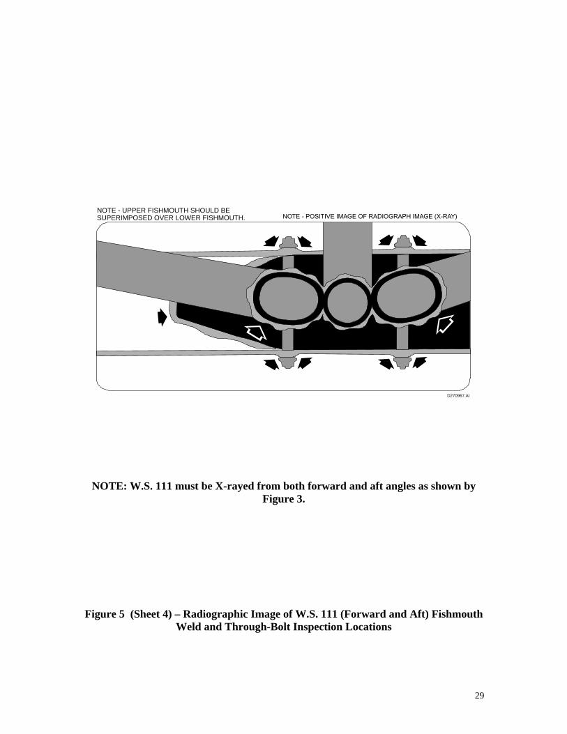
NOTE - UPPER FISHMOUTH SHOULD BE SUPERIMPOSED OVER LOWER FISHMOUTH.
NOTE: W.S. 111 must be X-rayed from both forward and aft angles as shown by Figure 3.
Figure 5 (Sheet 4) – Radiographic Image of W.S. 111 (Forward and Aft) Fishmouth Weld and Through-Bolt Inspection Locations
29

Figure 6 – Attach point of the Volpar truss to Beech spar truss assembly (W.S. 77)
30

Figure 7 – Attach point of the Volpar truss to Beech spar truss assembly (W.S. 32)
31

Figure 8 – Lower elliptical spar tube and 299-2 drag strut (W.S. 92)
32