bee code -cogeneration - tsredco · 2015-12-08 · bee code cogeneration prepared for bureau of...
TRANSCRIPT

BEE CODE
CCOOGGEENNEERRAATTIIOONN
Prepared for
Bureau of Energy Efficiency, (under Ministry of Power, Government of India) Hall no.4, 2
nd Floor,
NBCC Tower, Bhikaji Cama Place, New Delhi – 110066.
Indian Renewable Energy Development Agency, Core 4A, East Court, 1
st Floor, India Habitat Centre,
Lodhi Road, New Delhi – 110003.
By
Devki Energy Consultancy Pvt. Ltd., 405, Ivory Terrace, R.C. Dutt Road, Vadodara – 390007.
2006

2
CONTENTS
LIST OF FIGURES .................................................................................................................................................................3
LIST OF TABLES ...................................................................................................................................................................3
1. OBJECTIVE AND SCOPE .......................................................................................................................................4
1.1 OBJECTIVE................................................................................................................................................................4
1.2 SCOPE ......................................................................................................................................................................4
2. DEFINITIONS AND DESCRIPTION OF TERMS..................................................................................................6
2.1 SYMBOLS ..................................................................................................................................................................6
2.2 ABBREVIATIONS ........................................................................................................................................................6
2.3 SUBSCRIPTS .............................................................................................................................................................7
2.4 DEFINITIONS .............................................................................................................................................................7
2.5 CONSTANTS AND CONVERSIONS .............................................................................................................................11
3. GUIDING PRINCIPLES ..........................................................................................................................................12
3.1 INTRODUCTION........................................................................................................................................................12
3.2 ESTIMATION OF PERFORMANCE ..............................................................................................................................12
3.3 PRE TEST REQUIREMENTS ......................................................................................................................................12
3.4 PERFORMANCE PARAMETERS IN COGENERATION PLANT.........................................................................................13
3.5 MANUFACTURER’S PERFORMANCE AND CORRECTION CURVES AND DATA REQUIRED .............................................14
3.6 REQUIREMENTS DURING THE TEST .........................................................................................................................14
4. INSTRUMENTS AND METHODS OF MEASUREMENTS...............................................................................16
4.1 PERFORMANCE PARAMETERS IN COGENERATION PLANT.......................................................................................16
4.2 MEASUREMENTS.....................................................................................................................................................16
4.3 TEST INSTRUMENT ACCURACY ................................................................................................................................17
4.4 MEASUREMENT OF GENERATOR POWER OUTPUT ...................................................................................................17
4.5 MEASUREMENT OF FEED WATER, CONDENSATE, STEAM AND COOLING WATER FLOW .............................................17
4.6 MEASUREMENT OF FUEL FLOW ...............................................................................................................................18
4.7 MEASUREMENT OF PRESSURE ................................................................................................................................19
4.8 MEASUREMENT OF TEMPERATURE..........................................................................................................................19
4.9 MEASUREMENT OF ATMOSPHERIC CONDITIONS ......................................................................................................19
4.10 MEASUREMENT OF SHAFT SPEED .......................................................................................................................20
4.11 MEASUREMENT OF AIR FLOW AND EXHAUST FLUE GAS FLOW..........................................................................20
4.12 MEASUREMENT OF FLUE GAS COMPOSITION.......................................................................................................22
4.13 FUEL HEATING VALUE CALCULATIONS .................................................................................................................22
4.14 MEASUREMENT OF TIME.....................................................................................................................................22
4.15 MAXIMUM PERMISSIBLE VARIATIONS IN TEST CONDITIONS ..................................................................................23
5. PERFORMANCE CALCULATION PROCEDURE .............................................................................................24
5.1 CALCULATION PROCEDURES...................................................................................................................................24
5.2 EXTRACTION-CUM-CONDENSING STEAM TURBINE BASED COGENERATION PLANT ...................................................24
5.3 GAS TURBINE BASED COGENERATION PLANT ..........................................................................................................28
5.4 RECIPROCATING ENGINE BASED COGENERATION PLANT .........................................................................................32
6. REPORT OF TEST RESULTS AND SAMPLE CALCULATION .....................................................................37
6.1 CALCULATION PROCEDURE FOR GAS TURBINE BASED COGENERATION PLANT ........................................................37
6.2 FORMAT OF EQUIPMENT DATA AND FIELD TEST DATA COLLECTION..........................................................................37
6.3 FUEL FLOW CALCULATIONS .....................................................................................................................................40
6.4 DETERMINATION OF EFFICIENCY AND HEAT RATE...................................................................................................40
7. UNCERTAINTY ANALYSIS ..................................................................................................................................44
7.1 INTRODUCTION........................................................................................................................................................44
7.2 METHODOLOGY ......................................................................................................................................................44
7.3 UNCERTAINTY EVALUATION OF COGENERATION PLANT EFFICIENCY TESTING .......................................................46
8. PRACTICES FOR OPTIMAL PERFORMANCE OF COGENERATION SYSTEMS.....................................49
8.1 STEAM TURBINE SYSTEMS ......................................................................................................................................49
8.2 GAS TURBINE SYSTEMS ..........................................................................................................................................50
8.3 RECIPROCATING ENGINE SYSTEMS .........................................................................................................................51
ANNEXURE-1: CALCULATION OF EXHAUST FLUE GAS FLOW ............................................................................54
ANNEXURE-2: REFERECES.............................................................................................................................................56

3
List of figures Figure 4-1: Log Tchebycheff method for rectangular ducts ................................................................................... 21 Figure 4-2: Log Tchebycheff method for circular ducts ......................................................................................... 22 Figure 5-1: Steam turbine process flow with instrument locations......................................................................... 25 Figure 5-2: Gas turbine process flow with instrument locations ............................................................................ 28 Figure 5-3: Reciprocating Engine process flow with instrument locations............................................................. 33 Figure 5-2: Gas turbine process flow with instrument locations ............................................................................ 39
List of Tables Table 3-1: Performance parameters for various equipment in cogeneration plant ................................................ 13 Table 4-1: Measurement point location ................................................................................................................. 21 Table 5-1: Format of calculations-Steam turbine................................................................................................... 27 Table 5-2: Calculations for estimating overall efficiency and heat rate.................................................................. 36 Table 6-1: Cogeneration Power Plant Data Sheet ................................................................................................ 37 Table 6-2: Calculations for Gas Turbine Cogeneration Plant ................................................................................ 43 Table 7-1: Uncertainty evaluation sheet-1............................................................................................................. 45 Table 7-2: Uncertainty evaluation sheet-2............................................................................................................. 45 Table 7-3: Uncertainty evaluation sheet-3............................................................................................................. 45 Table 7-4: Instrument accuracy table .................................................................................................................... 46 Table 7-5: Measurements and Uncertainty analysis ............................................................................................. 47

4
1. OBJECTIVE AND SCOPE
1.1 Objective 1.1.1 The basic objective of this BEE Code is to establish procedures, guidelines and rules for
conducting the performance tests on different types of cogeneration Systems at site operating conditions. The code also provides, to the extent feasible, ways and means for improvement of performance.
1.1.2 The performance of cogeneration system is widely understood in terms of Efficiency and
Heat Rate. The objective of this code is to determine the Efficiency and Heat Rate for the cogeneration System operating at specific operating conditions prevailing at that site.
1.2 Scope 1.2.1 This code deals with the following types of cogeneration systems, which are further divided on
the basis of different types of main plant equipment installed and various types of fuels fired. Based on fuel Based on equipment configuration
i. Steam turbine based cogeneration system Coal/Lignite fired plant Back-pressure steam turbine Liquid Fuel fired plant Extraction & condensing steam turbine Natural gas fired plant Extraction & back-pressure steam turbine Bagasse/Husk fired plant Single/double extraction & condensing ii. Gas turbine based cogeneration system Natural gas fired plant Gas turbine with unfired Waste Heat Recovery Boiler (WHRB) Liquid fuel fired plant Gas turbine with supplementary fired WHRB Gas turbine with fully fired WHRB Gas turbine with WHRB & steam turbine [Cogeneration-cum-combined cycle] iii. Reciprocating engine based cogeneration system Liquid fuel fired plant Reciprocating engine with unfired WHRB Natural gas fired plant Reciprocating engine with supplementary fired WHRB Reciprocating engine with fully fired WHRB Reciprocating engine with absorption chiller
1.2.2 Following Codes and Standards are widely used as reference while preparing the code, as these are widely used for conducting performance testing at manufacturers’ test facilities and at operating site.
Steam Turbines DIN 1943 Thermal acceptance tests for steam turbines BN EN 60953 Rules for steam turbine’s thermal acceptance tests ASME PTC 6 Steam turbine performance test code IEC 953 Rules for steam turbine’s thermal acceptance tests Gas Turbines DIN 4341 Acceptance rules for gas turbines BS 3135 Specification for gas turbine acceptance test ASME PTC 22 Gas turbine power plants – Power test code ISO 2314 Gas turbines - Acceptance tests ISO 2314 Acceptance tests for combined cycle power plants, Amendment 1

5
Reciprocating Engines IS:10000 Part IV – 1980: Method of tests for Internal combustion engines
Declaration of power, efficiency, fuel consumption and lubricating oil consumption
IS:10000 Part VIII – 1980: Method of tests for Internal combustion engines Performance tests
Steam Boilers ASME PTC 4.1 Steam generating units performance test code ASME PTC 4.4 Gas turbine heat recovery steam generators performance test code DIN 1942 Acceptance Test for Steam Generators The performance of fired steam generating plant can be determined in accordance with the
method provided in the respective Codes for Boilers and the performance parameters so derived can be used to determine overall performance of the cogeneration plant.
6
2. DEFINITIONS AND DESCRIPTION OF TERMS
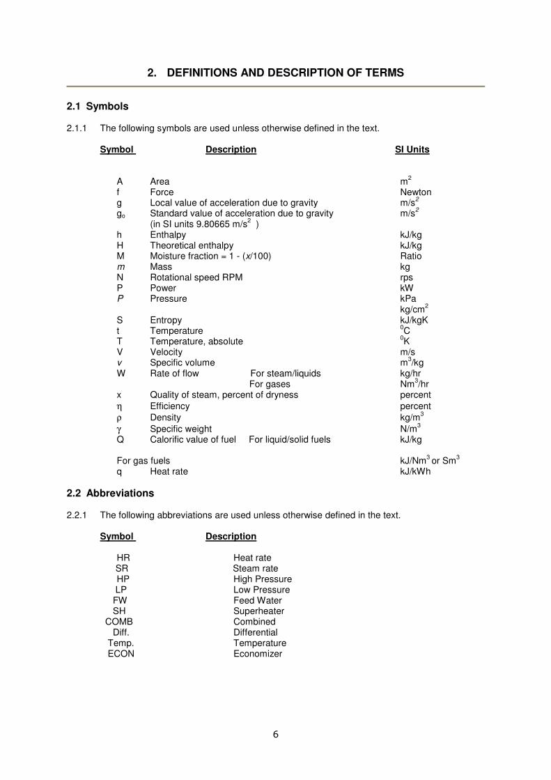
2.1 Symbols 2.1.1 The following symbols are used unless otherwise defined in the text. Symbol Description SI Units
A Area m2
f Force Newton g Local value of acceleration due to gravity m/s
2
go Standard value of acceleration due to gravity m/s2
(in SI units 9.80665 m/s2 )
h Enthalpy kJ/kg H Theoretical enthalpy kJ/kg M Moisture fraction = 1 - (x/100) Ratio m Mass kg N Rotational speed RPM rps P Power kW P Pressure kPa kg/cm
2
S Entropy kJ/kgK t Temperature
0C
T Temperature, absolute 0K
V Velocity m/s v Specific volume m
3/kg
W Rate of flow For steam/liquids kg/hr For gases Nm
3/hr
x Quality of steam, percent of dryness percent
η Efficiency percent
ρ Density kg/m3
γ Specific weight N/m3
Q Calorific value of fuel For liquid/solid fuels kJ/kg
For gas fuels kJ/Nm3 or Sm
3
q Heat rate kJ/kWh
2.2 Abbreviations 2.2.1 The following abbreviations are used unless otherwise defined in the text. Symbol Description
HR Heat rate
SR Steam rate HP High Pressure LP Low Pressure FW Feed Water SH Superheater COMB Combined Diff. Differential
Temp. Temperature ECON Economizer

7
2.3 Subscripts 2.3.1 The following subscripts are used unless otherwise defined in the text.
Subscript Description G Generator r Rated condition c Corrected stg Steam turbine gt Gas turbine en Reciprocating engine blr Boiler, waste heat recovery f fuel steam Steam ng Natural gas fuel lq Liquid fuel wtr Water s Specified operating condition, if other than rated t Test operating condition 1 Conditions measured at the steam turbine inlet stop valves and steam
strainers 2 For turbines using superheated steam: condition at 1
st extraction
3 For turbines using superheated steam: condition at 2nd
extraction 4 Condition at turbine exhaust connection 5 Condition at condenser-condensate discharge 6 Condition at condensate pump discharge 7 Condition at feed-water pump or feed-water booster pump inlet 8 Condition at feed-water pump discharge 9 Condition at the discharge of the final feed-water heater a1 Superheater-desuperheating water a2 First reheater desuperheating water a3 Second reheater desuperheating water E Extraction steam. e Make-up water admitted to the condensate system hhv Higher heating value lhv Lower heating value pL Packing leak-off (shaft or valve stems) i, ii…n Sequence
2.4 Definitions
Approach Point It is difference between the saturation temperature and the water temperature entering the evaporator.
Auxiliary power/energy All electricity consumed internally within the boundary of a
cogeneration plant to run the plant. Calorific value, gross Gross calorific value of fuel in kJ/kg. Heat evolved per kg of
fuel (for solid and liquid fuels) and per Nm3
(normal cubic meter)/Sm
3 (standard cubic meter) of fuel (for gas fuels) in its
complete combustion under constant pressure at temperature of 25
0C when all the water initially present as liquid in the fuel
and that present in the combustion products condensed to the liquid state.
Calorific value, net Net calorific value of fuel in kJ/kg. Heat evolved per kg of fuel
(for solid and liquid fuels) and per Nm3
(normal cubic meter)/Sm
3 (standard cubic meter) of fuel (for gas fuels) in its

8
complete combustion under constant pressure at temperature of 25
0C when all the water initially present as liquid in the fuel
and that present in the combustion products in the vapour state. (The number of heat units liberated per unit quantity of fuel burned in oxygen under standard conditions).
Capacity Useful output produced by generator driven by steam turbine,
gas turbine or engine expressed in terms of the functional output in terms of horsepower, kilowatt; also referred to as maximum continuous rating (MCR).
Capacity factor Total energy produced for a specified period relative to the
total possible amount of energy that could have been produced for the same period.
hoursPeriodx(kW)capacityinstalledTotal
100%x(kWh)periodthatingeneratedenergyTotal
Carbon (C) Carbon in fuel, expressed as mass % as-received, as-sampled
or as-fired (Cas); and for coal, mass % dry ash-free (Cdaf). Cogeneration/combined Simultaneous production of useful energy in different heat and power (CHP) forms (heat, typically as steam) and electrical energy. Combustion, Rate of Rate of combustion is defined as follows. (a) All fuels: Heat value of fuel as fired per unit of furnace volume
per unit time, J/(m3*s)
(b) Mass burning of solid fuels: Mass of fuel as fired per unit area grate surface per unit time, kg/(m
2*s)
(c) Gaseous fuels: Volume of gas fired per unit of furnace volume per unit time, m
3*s.
Combustor A heat source in which fuel burns and produces hot flue gases
to feed in turbine or otherwise reacts with the working fluid to increase the temperature.
Efficiency, Ideal Cycle Ideal cycle efficiency is defined as the ratio of the work of the
ideal cycle to the heat input. This efficiency of an ideal cycle is often referred to as the efficiency of an ideal engine.
Efficiency, Engine The engine efficiency is defined as the ratio of actual work of a
system divided by the work of a corresponding ideal system. Since indicated, brake, or combined actual work may be involved, it is possible to have three engine efficiencies.
Efficiency, Thermal The thermal efficiency is defined as the ratio of energy output
to energy input or work done divided by the heat supplied. It is directly related to heat rate.
Indicated thermal efficiency = AWi / Q Brake thermal efficiency = AWb / Q Combined thermal efficiency = BWk / Q

9
Where, A = 1 J/(W*s) B = 1 J/(W*s) Q = heat added, J/sec Wi = indicated net work, J Wb = brake net work, J Wk = combined net work, J The thermal efficiency of a complete plant will be expressed in
the same manner as that for a turbine or engine. Efficiency, Volumetric Volumetric efficiency is derived only for reciprocating engines.
100xntDisplaceme
deliveryActualηv =
Efficiency, Isentropic The isentropic compression efficiency is defined as ratio of Compression theoretical isentropic power to the fluid power developed. Efficiency, Mechanical Mechanical efficiency is defined as the ratio of actual work to
indicated internal work. Efficiency, Overall, Overall compressor efficiency is defined as ratio of Compressor isentropic power to the actual power supplied. Energy of a Substance, Internal energy of a substance is a “Point” function Thermal Enthalpy Enthalpy of water or steam is the amount of heat that must be
added to bring it from a liquid at 00C to its present
temperature, pressure and condition. It is expressed in terms of kJ/kgm.
Enthalpy is defined as: kJ/kgP
u h J
v+=
Where, h = enthalpy, kJ/kg u = internal energy, kJ/kg P = pressure of fluid, kPa v = specific volume of fluid, m
3/kg
J = mechanical equivalent of heat, 1 kJ/1000J Enthalpy drop The difference in enthalpy between steam at the steam turbine
inlet conditions and at steam turbine outlet conditions. Entropy It is ratio of the heat added to a substance to the absolute
temperature at which it was added. Fossil fuels Energy-rich substances created from the partial decomposition
of prehistoric organisms over long periods of time. Examples are coal, coal seam methane, natural gas, and oil.
Fuel rate The fuel rate of solid and liquid fuels is defined as mass of fuel
fired per unit of output. For gaseous fuels, it is defined as m3 of gas at 150C and 101.325 kPa pressure per hour. Fuel rate should be qualified by reference to the unit output.
Heat Rate Heat rate is the amount of energy input required to produce a
given unit output, usually expressed as kJ/kWh, Heat rate is a measure of generating station heat efficiency.

10
This is the total fuel heat input expressed in kJ divided by the energy produced by the power plant expressed in kWh. It is related to thermal efficiency by the following expression (%).
kWhofunitsingiven100%xefficiencyThermal
3600HR =
Higher heating value This is synonymous with gross calorific value. (HHV) Lower heating value This is synonymous with net calorific value. (LHV) Non-recoverable The component of degradation in the sent-out thermal degradation (NRD) efficiency of a power plant due to ageing that is not
recoverable through normal maintenance practices. Note that this degradation is normally measured as an increase in heat rate.
Output factor (or load Total energy produced for a specified period relative to factor) the total possible amount of energy that could have been
produced for the service hours during the same period.
%hoursservicex(kW)capacityinstalledTotal
100x(kWh))periodthatingeneratedenergyTotal
The term output factor is intended to apply to electricity generators and may not be directly applicable to some cogeneration plants.
Period hours Period hours are the number of hours the unit was in an active state.
Pinch Point It is difference between the flue gas temperature leaving the
evaporator and saturation temperature in waste heat boiler. Power output, gross The gross power output of a generator unit is total electrical
energy generated during that specific duration of operation of unit.
Power output, net The net power output of a generator unit is defined by following
formulae.
supplied
powerAuxiliary generator ofoutput
power Electrical kW output,Net −=
Auxiliary power supplied is that external power which is necessary for the unit’s operation inclusive of, but not limited to excitation power, power for separately driven lube-oil pumps, boiler pumps, cooling water pumps, fuel pumps, fans, etc.
Service hours Total number of hours a unit was electrically connected to the transmission system. For a twelve month reporting period, the service hours correspond to the period for which electricity was metered; i.e., corresponding to the kWhs for the period.
Steam rate Steam consumption per hour per unit output, in which the
steam turbine is charged with the net steam quantity supplied, usually expressed in kgm/kWh.

11
GENGeneratedEfficiencyThermal
η %consumedfuelofvaluecalorificgrossxfuelofQuantity
100x3600x(kWh)generatedenergyTotal
SOSentoutEfficiencyThermalη,
%consumedfuelofvaluecalorificgrossxfuelofQuantity
100x3600x(kWh)outsentenergyTotal
Total installed capacity Total installed capacity is the sum of the capacity for each unit
making up the power plant, where capacity is as defined above. Also see definition of “service hours”.
Turbine A mechanical expander device in which the working fluid
produces work kinetic action on a rotating element.
2.5 Constants and conversions 2.5.1 Following conversion factors can be used in calculations.
g0 = Standard value of acceleration due to gravity; = in SI units 9.80665 metres per sec. per sec. This is an internationally agreed value.
J = Mechanical equivalent of heat; 1 kJ = 0.102 N. One hp (Electric) = 0.746 kW. One kCal = 4.19 kJ

12
3. GUIDING PRINCIPLES
3.1 Introduction 3.1.1 To carry out the onsite performance in correct and satisfactory manner, careful planning and
proper execution are essential at every stage of the test. In this section, various requirements before, during and after conducting of equipment performance test are discussed.
3.2 Estimation of performance 3.2.1 The performance of Cogeneration System is widely understood in terms of Efficiency and
Heat Rate. Heat rate is the heat input required per unit of power generated (kJ/kWh), for specific fuel being fired and specific site conditions.
3.2.3 Performance testing of Cogeneration system defined in this code include the following.
• Measurement and estimation of Power Generation from the cogeneration plant at the site operating parameters of ambient air temperature, pressure and relative humidity, site altitude, fuel being fired and its characteristics.
• Measurement and estimation of Steam Generation from the cogeneration plant from waste heat recovery in gas turbine based plants and reciprocating engine based plants.
• Estimation of Cogeneration Heat Rate or Heat Input per unit and Cogeneration Efficiency at the site operating parameters of ambient air temperature, pressure and relative humidity, site altitude, fuel being fired and its characteristics.
• Measurement and estimation of Auxiliary Power Consumption at the site operating parameters.
3.3 Pre test requirements 3.3.1 Before performance evaluation test can be undertaken, it is important to conduct careful
review of the required documents inclusive of the Process and Instrumentation Diagrams (P & IDs) for the plant and system. It is also suggested to prepare a test-protocol on the following lines.
• Name of equipment to be subjected to test.
• Performance maps and performance guarantee values at installation.
• Understanding of the test procedures to be followed as defined in this code including explicitly stated exceptions, if any.
• Test Data to be collected including methods of measurements, instruments to be used for critical parameters.
• Performance analysis procedure to be adopted as per code.
• Present operating conditions of equipment and operating hours logged.
• Check for calibration of on site & on line instruments to be used for measurement of critical parameters.
• Typical test data logged automatically in in-built control system or DCS.
• Time duration for test and minimum number of tests.
• Operating parameters under which the performance needs to be evaluated for each equipment in the system.
3.3.2 Once the test-protocol on above mentioned lines has been defined and agreed upon, a final
test procedure conforming to this code including required test-data sheets is prepared. At this

13
stage, it may be necessary to give special instructions to the plant operating personnel such as off-line washing of the gas turbine prior to undertaking the test.
3.3.3 A plan for instrumentation required for the test of system and system heat cycle can be drawn
out prior to test. This plan should take into account the instruments installed as part of cogeneration system and to be installed for the purpose of test.
Adequate provision for physical location, installation and number of test instruments needed to achieve test results with good repeatability should be made. Some of the items to be considered are:
(a) Location and installation of a calibrated primary flow metering section.
(b) Provision for the accurate measurement of output.
(c) Location and installation of test connections for primary pressure and temperature measurements.
(d) Provision for measurement of secondary leak-off and bypass flows, which may affect the primary flow measurement or have a significant effect in calculation of the test performance.
(e) Selection of test instruments capable of the repeatability required for consistent test results.
(f) Location of test instruments in groups to facilitate calibration and use, and minimize the number of observations required.
3.3.4 The performance parameters, commonly considered for performance guarantee and specific
for onsite performance testing, are given in Table 3.1 for main components or equipment installed in cogeneration plant. The cogeneration plant configuration can be based on the combination of different systems given in the table.
3.4 Performance parameters in cogeneration plant 3.4.1 Estimation of following parameters need to be carried out in performance testing in
cogeneration plant.
Table 3-1: Performance parameters for various equipment in cogeneration plant
Equipment Performance parameter Associated parameter
Gas turbine generator system
• Electric Power Output
• Heat Rate
• Exhaust Gas Temperature
• Compressor Inlet Temperature
• Ambient Pressure
• Compressor Inlet Relative Humidity
• DeNOx Steam Flow Conditions (pressure, temperature, flow rate)
Steam turbine generator system
• Electrical Power Output
• Heat Rate
• Steam Turbine Throttle Flow Conditions (temperature, pressure, flow rate)
• DeNOx Steam Flow Conditions (temperature, pressure, flow rate)
• Process Steam Flow Conditions (temperature, pressure, flow rate)
Reciprocating engine generator system
• Electric Power Output
• Heat Rate
• Exhaust Gas Temperature
• Engine Inlet Temperature
• Ambient Pressure
• Engine Inlet Relative Humidity
Waste heat recovery boiler
• HP Steam Flow Rate
• Overall Effectiveness of System
• Combined Economizer Feed water flow
• Gas temperature in HRSG inlet
• Exhaust Gas Flow
• Supplementary Firing Conditions
• Exhaust Gas Composition at HRSG inlet
14
Note: Above listed parameters are based on assumption of single pressure HRSG system. In case of dual pressure HRSG system, there can be HP as well as LP steam flow rate and other conditions can be taken as the case may be.
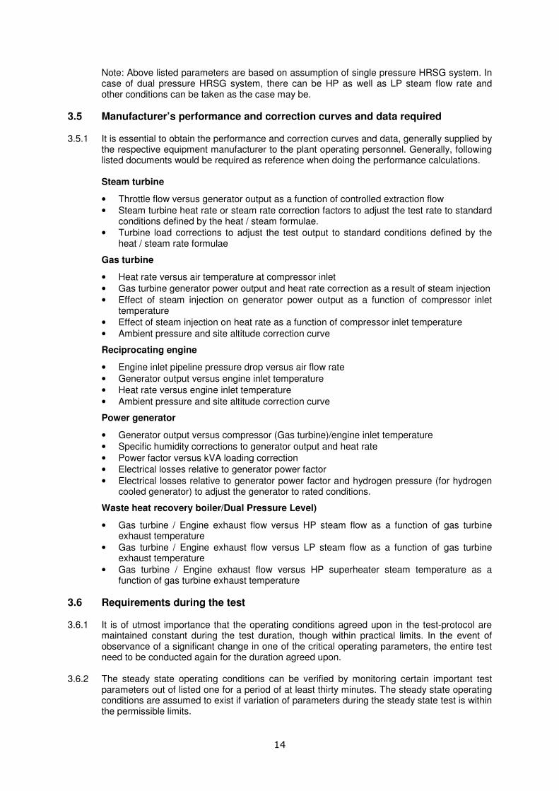
3.5 Manufacturer’s performance and correction curves and data required 3.5.1 It is essential to obtain the performance and correction curves and data, generally supplied by
the respective equipment manufacturer to the plant operating personnel. Generally, following listed documents would be required as reference when doing the performance calculations.
Steam turbine
• Throttle flow versus generator output as a function of controlled extraction flow
• Steam turbine heat rate or steam rate correction factors to adjust the test rate to standard conditions defined by the heat / steam formulae.
• Turbine load corrections to adjust the test output to standard conditions defined by the heat / steam rate formulae
Gas turbine
• Heat rate versus air temperature at compressor inlet
• Gas turbine generator power output and heat rate correction as a result of steam injection
• Effect of steam injection on generator power output as a function of compressor inlet temperature
• Effect of steam injection on heat rate as a function of compressor inlet temperature
• Ambient pressure and site altitude correction curve
Reciprocating engine
• Engine inlet pipeline pressure drop versus air flow rate
• Generator output versus engine inlet temperature
• Heat rate versus engine inlet temperature
• Ambient pressure and site altitude correction curve
Power generator
• Generator output versus compressor (Gas turbine)/engine inlet temperature
• Specific humidity corrections to generator output and heat rate
• Power factor versus kVA loading correction
• Electrical losses relative to generator power factor
• Electrical losses relative to generator power factor and hydrogen pressure (for hydrogen cooled generator) to adjust the generator to rated conditions.
Waste heat recovery boiler/Dual Pressure Level)
• Gas turbine / Engine exhaust flow versus HP steam flow as a function of gas turbine exhaust temperature
• Gas turbine / Engine exhaust flow versus LP steam flow as a function of gas turbine exhaust temperature
• Gas turbine / Engine exhaust flow versus HP superheater steam temperature as a function of gas turbine exhaust temperature
3.6 Requirements during the test 3.6.1 It is of utmost importance that the operating conditions agreed upon in the test-protocol are
maintained constant during the test duration, though within practical limits. In the event of observance of a significant change in one of the critical operating parameters, the entire test need to be conducted again for the duration agreed upon.
3.6.2 The steady state operating conditions can be verified by monitoring certain important test
parameters out of listed one for a period of at least thirty minutes. The steady state operating conditions are assumed to exist if variation of parameters during the steady state test is within the permissible limits.

15
3.6.3 Moreover, in a given test-set, it is necessary to ascertain that the variation in values of
different measured parameters compared to their respective test average have not exceeded the permissible limits provided under the applicable test codes or standards.
3.6.4 As it is feasible to install different combinations of power and steam generation equipment in
cogeneration plant, the test procedure for each cogeneration plant can be developed individually based on the plant configuration, instrumentation and plant operating conditions.

16
4. INSTRUMENTS AND METHODS OF MEASUREMENTS
4.1 Performance Parameters in Cogeneration Plant 4.1.1 Measurement of some or all of the following parameters can be carried out for performance
testing in cogeneration plant. 4.1.2 For the performance evaluation of cogeneration system, following test data can be generally
collected. a. Gas turbine generator System 1 Ambient Pressure 4 Electrical Power output 7 Diff. Pressure-Inlet Air Filter 2 Dry Bulb Temp. 5 Fuel Flow Rate 8 Exhaust Gas Temp 3 Wet Bulb Temp. 6 Fuel Gas Temp. 9 Auxiliary Power b. Steam turbine generator system 1 Throttle Steam-flow, 3 Exhaust Steam Pressure, 6 Auxiliary Steam Flow Pressure & Temp. & Temp. 2 Extraction Steam-flow, 4 Electrical Power output Pressure & Temp. 5 Auxiliary Power c. Reciprocating engine generator system 1 Ambient Pressure 5 Electrical Power output 8 Diff. Pressure-Inlet Air Filter 2 Dry Bulb Temp. 6 Fuel Flow Rate 9 Exhaust Gas Temp 3 Wet Bulb Temp. 7 Fuel Gas Temp. 10 Auxiliary Power 4 Jacket Water Temp. d. Waste Heat Recovery Boiler (WHRB) 1 Exhaust Gas Temp. 8 HP FW-Flow, Pressure 15 HP SH Exit Temp. inlet HP SH & Temp. 2 Exhaust Gas Temp. inlet HP EVAP 9 LP Drum Pressure 16 HP SH Exit Pressure 3 Exhaust Gas Temp. inlet HP ECON 10 HP Drum Pressure 17 COMB ECON HP FW Inlet Temp. 4 Exhaust Gas Temp. inlet 11 LP HRSG Steam Flow, 18 COMB ECON HP FW COMB ECON Pressure & Temp. Exit Temp. 5 Exhaust Gas Temp. exit 12 HP WHRB Steam Flow, 19 LP WHRB Blowdown WHRB flow Pressure & Temp. 6 Exhaust Gas Diff. Pressure 13 COMB ECON LP FW 20 HP WHRB Blowdown WHRB Inlet Temp. 7 LP FW Flow, Pressure & Temp. 14 COMB ECON LP FW 21 Flue Gas Analysis COMB ECON Exit Temp. at Inlet WHRB
4.2 Measurements 4.2.1 Measurement and estimation of the following listed parameters need to be done during the
test run in accordance with the type of the cogeneration plant. (a) Generator power output, power factor, voltage, current, reactive load (b) Feed water flow, temperature (c) Condensate flow, temperature (d) Steam flow, pressure, temperature (e) Cooling water flow, temperature (f) Fuel flow & total consumption (g) Fuel pressure (h) Fuel temperature (j) Atmospheric (Ambient) conditions, pressure, temperature, humidity, flow

17
(k) Shaft speed (l) Exhaust gas (flue gas flow) – for gas turbines and reciprocating engines (m) Flue gas analysis (n) Fuel analysis
4.3 Test instrument accuracy 4.3.1 Instruments to be used during test is recommended to have following accuracy tolerances. Instrument Accuracy Inlet air RTD, Thermocouples 0 – 1000C, ± 0.35% (chrome alumel) Exhaust air/flue gas RTD 0 – 1000C, ± 0.35% Speed indication ± 1 rev/min, digital counter Fuel weighing measurement ± 1 % Fuel flow meter measurement ± 1 % (gas and liquid fuels) Water flow meter measurement ± 1 % Pressure instruments ± 1 % Temperature instruments ± 1 % Power measurement ± 0.5 % Current transformer accuracy class 0.5 Voltage transformer accuracy class 0.5 4.3.2 The calibration of the test instruments should be established prior to the test run. The valid
calibration certificate, not more than six months old, conforming to ISO Quality Standards, for all the instruments installed in the field and used as portable along with the traceability should be available for verification prior to test.
4.4 Measurement of generator power output 4.4.1 Electrical measurements can be carried out by any one of the following methods.
(a) Calibrated portable power analyzer used with integrated clamp on current transformers and voltage input from system potential transformers (for HT voltage). This instrument is preferred for site testing. Power analyser need to be calibrated in the power factor ranging from 0.5 to 1.0.
(b) Calibrated three-element test watt-hour meter, used with separate potential and current transformers, transformers to be calibrated with equivalent meter burden with no additional burden in the metering circuit.
(c) Same as (b), but with two-element watt-hour meter instead of three element watt-hour meter.
4.4.2 Instruments can be located so that the total generator output is measured. In case of
existence of any external tap between the generator and the point of measurement, supplementary metering of equivalent accuracy may be provided to determine the total generator output.
4.4.3 For measurement of auxiliary power supplied to drive support equipment within the battery
limit of the cogeneration plant, the method of measurement of auxiliary power can be identical to the one of (a), (b) or (c).
4.5 Measurement of feed water, condensate, steam and cooling water flow 4.5.1 Feed water flow and Condensate flow – It is recommended to use measured feed water flow
as the basis for the accurate determination of the primary flow to the turbine.

18
The primary element for water flow measurement can be an orifice/venture/ vortex flow meter designed meeting the specification of fluid and system and installed in a specially designed flow metering pipe section.
4.5.2 Steam flow – It is recommended to use orifice/vortex based flow measurement system similar
to the one to be used for feed water flow measurement with some exceptions and additions considering the requirement of measuring the flow similar to gaseous flow. Because of the inherent difficulties in installation and calibration of flow measuring stations to be used for measuring primary steam flow at high pressure and temperature steam turbines, the use of a flow measuring device in the low temperature portion of the water cycle may also be considered to determine primary steam flow to the turbine. For measuring flow of very high pressure steam, steam flow nozzles may be used.
4.5.3 Cooling water flow –In the absense of in-line flow meters, use the portable ultrasonic flow
measurement instrument can be considered. The V-notch or weir type of metering station can also be considered. Wherever, specific accuracy is required, the method mentioned in 4.5.1 may be used.
4.6 Measurement of fuel flow
It is essential that highly accurate, reliable and calibrated metering system is available to obtain the quantity of fuel supplied to the cogeneration plant during the the performance testing. Fuel being the primary source of energy, any minor deviation in accuracy of quantity of fuel greatly affects the performance of cogeneration plant.
4.6.1 Measurement of fuel quantity
4.6.1(a) Gaseous fuels For measurement of flow and quantity of gaseous fuel during the performance test, one of the following methods depending on its availability can be considered.
At most of the site locations of cogeneration plants, a microprocessor based latest online gas fuel flow and quantity measurement system, installed by the fuel supplying agency, is generally be available. Such systems are generally calibrated every three months due to requirement of accurate billing for the gas supplied. The data available through such instrumentation system can be used for the performance derivation of the cogeneration plant. However, it should be ensured that the quantity of gas received is supplied in totality to cogeneration plant. If gas is supplied to other area, then the proposed arrangement to obtain data for gas flow and quantity can not work.
Besides the fuel supplying agency’s metering system, normally, a microprocessor based online gas fuel flow and quantity measurement system is generally available, integrated with the control and instrumentation system of individual gas turbine unit or reciprocating engine unit, with continuous display of instantaneous gas flow and flow totalisers. It should be ensured that the instruments forming the part of the system are calibrated within the six month period prior to the date of performance test. In case there are multiple units with a common fuel metering system, another method have to be adopted for obtaining the data of fuel flow and quantity for individual unit. Calculation of gas volume at standard conditions from measured gas volume using following relation.
x Z)273m( x 325.101
288 x w)m(xVmVs
+
−=
T
PP
Where, Vs = total gaseous fuel volume in standard m
3
Vm = measured or calculated volume at test conditions, m3
Pm = measured gas pressure, mm Hg Pw = water vapour pressure mm Hg, (zero for dry gas)

19
Tm = measured gas temperature, 0C
Z = compressibility factor for gas at following temperature/pressure
4.6.1(b). Liquid fuels For liquid fuel flow and consumption, either of following suggested metering system can be used.
To measure liquid fuel flow in pipelines, it is recommended to use digital readout on a control panel of equipment being fired with liquid fuel. The method of measurement is similar to 4.6.1 If the system mentioned at 4.6.1 (a) is not installed, and if the liquid fuel is clear such as Kerosene, Light diesel oil or High speed diesel, the portable ultrasonic flow measurement unit may be used.
4.7 Measurement of pressure 4.7.1 Following instruments can be used for measuring pressure.
(a) For measuring the steam pressure at various points on the steam circuit, fuel gas pressure and other relevant pressures, the Bourdon gauges of required ranges can be used, which should be calibrated against standard dead weight gauge or a master gauge. The graduations should permit readings within ± 1% percent of the expected pressure measurement. In place of Bourdon gauges, digital pressure gauge with accuracy of 0.25% percent can also be used.
(b) The pressures can also be taken for certain parameters from the digital readout on the control panel, which will generally be getting signals from the online precision pressure instrumentation such as pressure transmitters.
(c) For measurement of low pressures of less than 0.2 MPa (absolute), manometers can be used.
4.8 Measurement of temperature 4.8.1 Following instruments can be used for measuring temperature.
(a) For measuring the temperature of steam at various points on the entire steam circuit, the calibrated thermocouples or resistance temperature detectors (RTDs) installed online or on equipment can be used. Wherever, the provision of thermo-well is made, calibrated mercury-in-glass thermometers can also be used.
(b) The temperatures can also be taken for certain parameters from the digital readout on the control panel, which will generally be getting signals from the online precision temperature instrumentation such as thermocouple or RTD based temperature transmitters.
(c) The instrument for temperature measurement can be so chosen that it can read with an accuracy of ± 1% percent of the absolute temperature. Absolute value of full-scale error can not exceed 1
0C.
Special attention need to be paid in location of points for pressure and temperature measurements, where these readings are used to determine steam enthalpy in the steam circuit. Pressure taps need to be located as close as possible to the point of corresponding temperature measurement.
4.9 Measurement of atmospheric conditions 4.10.1 Atmospheric pressure can be measured using either a barometer or can be obtained from
standard meteorological data. The temperature can be measured using a calibrated mercury-

20
in-glass thermometer installed at prominent location. Standard dry and wet bulb thermometers can also be used for measuring temperature and to determine humidity level for correcting the calculations.
4.10 Measurement of shaft speed 4.11.1 The shaft speed can be taken from the digital readout on the control panel visual display unit
and data logger fed with signal from magnetic induction pick-up installed on the turbine or engine as the case may be.
4.11 Measurement of Air Flow and Exhaust Flue Gas Flow 4.12.1 For testing purposes, pitot tube/manometer can be used for measurement of air flow. Pitot
tube is recommended to be suitable for velocities more than 3 m/s and for temperature up to 700
0C. For lower air velocities, anemometer can be used. Both instruments have limitations
as follows.
(a) Pitot tube: This instrument can only be used in powder free clean air systems after the cyclone/bag filter. The point of measurement should ideally have six diameters of straight duct length before the measurement point. Also, the use of pitot tube should not be attempted at positions closer than one duct diameter to any upstream bend or damper. The static holes of the pitot must be free from burrs, clean and without having any dents. While, measuring, the angle of deviation of the pitot from the air stream must be zero, otherwise with 10
0 misalignment, the deviation from true
reading can be up to 5%.
(b) Anemometer: The anemometer is not suitable for hot powder laden airflow or ducts handling corrosive/explosive air-gas mixtures. Anemometer can have ± 1% accuracy.
(c) The pitot tube/anemometer measurements can be carried out to determine velocity profile over the duct as discussed hereunder as per Log Tchebycheff method and average velocity can be determined from the readings. Volumetric flow is derived from cross sectional area and mass flow is calculated from the humid volume of the air-water mixture.
(d) Exhaust gas flow can also be estimated from measured CO2 in flue gases and flue gas temperature, based on ultimate analysis of fuel. A sample calculation of exhaust flue gas flow rate for a gas turbine system is given in Annexure-1.
4.12.2 Log Tchebycheff method for rectangular ducts
Refer to Fig. 4.1. The intersection points of vertical and horizontal line are the points where the airflow measurement is required. For width H and height V, the location of points is indicated in the figure. Airflow is obtained by multiplying average velocity measured at all points with area.

21
0.061H
0.235H
0.939H
H
V
0.437H
0.563H
0.765H
0.074V
0.926V
0.712V
0.50V
0.288V
Figure 4-1: Log Tchebycheff method for rectangular ducts
Table is provided hereunder, which indicates location of measurement for rectangular
ducts.
Table 4-1: Measurement point location
Nos. of transverse lines
5 (for H<39”) 6 (for 36”>H>30”) 7 (for H>36”)
0.074 0.061 0.053
0.288 0.235 0.203
0.500 0.437 0.366
0.712 0.563 0.500
0.926 0.765 0.634
0.939 0.797
0.947
4.12.2 Log Tchebycheff method for circular ducts
Refer to Fig. 4.2. The duct is divided into concentric circles, applying multiplication factors to the diameter. An equal number of readings are taken from each circular area, thus obtaining the best average. Airflow is obtained by multiplying average velocities measured at all points within the area.

22
0.032 dia
0.135 dia
0.321 dia
0.679 dia
0.968 dia
dia
0.865 dia
Figure 4-2: Log Tchebycheff method for circular ducts
4.12 Measurement of flue gas composition 4.13.1 The flue gas analyzer having facility for Oxygen analysis using Zirconium probe is
recommended to be used online to measure flue gas components at sampling provided.
4.13 Fuel heating value calculations The heating value gaseous fuels and liquid fuels can be obtained either from the fuel supplying agency or sample can be collected during the test run and given for testing to recognized laboratory / institution and the results so provided for higher and lower heating values are to be used in the calculations. For testing of fuel, the laboratory should carry out the testing in accordance with the test methods for such property prescribed under the relevant Indian or International Standards.
4.14 Measurement of Time 4.14.1 The measurement of time of test durations and other observations can be determined by
observations of synchronized stop watches by the individual observers. Watches and clocks can be synchronized at the start of the test.
23
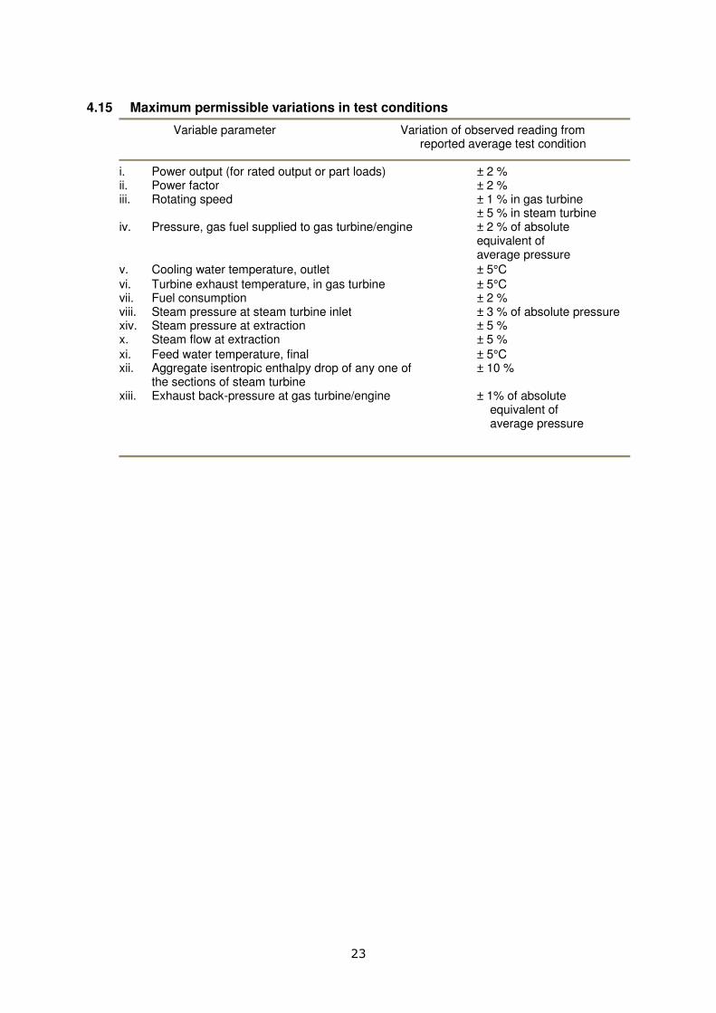
4.15 Maximum permissible variations in test conditions
Variable parameter Variation of observed reading from reported average test condition
i. Power output (for rated output or part loads) ± 2 % ii. Power factor ± 2 % iii. Rotating speed ± 1 % in gas turbine ± 5 % in steam turbine iv. Pressure, gas fuel supplied to gas turbine/engine ± 2 % of absolute equivalent of average pressure
v. Cooling water temperature, outlet ± 5°C
vi. Turbine exhaust temperature, in gas turbine ± 5°C vii. Fuel consumption ± 2 % viii. Steam pressure at steam turbine inlet ± 3 % of absolute pressure xiv. Steam pressure at extraction ± 5 % x. Steam flow at extraction ± 5 %
xi. Feed water temperature, final ± 5°C xii. Aggregate isentropic enthalpy drop of any one of ± 10 % the sections of steam turbine xiii. Exhaust back-pressure at gas turbine/engine ± 1% of absolute equivalent of average pressure

24
5. PERFORMANCE CALCULATION PROCEDURE
5.1 Calculation procedures 5.1.1 In view of feasibility of number of combinations of power and steam generation equipment in
cogeneration system, the calculation procedure for each cogeneration plant can be developed individually based on the plant configuration, instrumentation and plant operating conditions. Few methods are outlined in this section for the determination of performance parameters based on test.
5.2 Extraction-cum-condensing steam turbine based cogeneration plant 5.2.1 Basic formulae used in procedure
(a) Steam turbine cycle heat rate is defined as ratio of the heat supplied to the steam and water in the boiler to output from the turbine. The quantity of heat is calculated from the measurement of the total heat supplied to the boiler and of boiler efficiency by the loss method.
outputpower
waterandsteamtoinputHeatrateheatcycleTurbine =
outputpower
lossesboilerboilerinput toheat Total −=
%100xboilertohTotal
lossesboilerboiler TotalEfficiencyBoiler
inputeat
toinputheat −=
outputpower
efficiencyboilerxboilertohTotalrateheatcycleTurbine
inputeat=
(b) The definition does not consider heat additions and removals in boiler feed pumps, jet
air ejectors, etc. (c) The waste heat recovery boiler losses and credits considered under this procedure
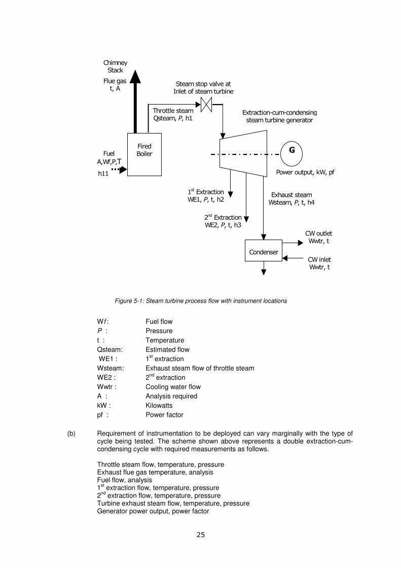
are as follows. Losses (1) Dry flue gas (2) Moisture from burning of hydrogen (3) Moisture in air (4) Surface radiation and convection losses Credits (1) Heat supplied through fuel, if fired in WHRB 5.2.2 Instrumentation requirements (a) Typical diagram showing location of instruments for measuring various variables is
given in Fig. 5.1. Some of the variables can be estimated from the manufacturer’s data as indicated on the figure.
25
G
Extraction-cum-condensing steam turbine generator
Fired Boiler
Chimney Stack
Fuel
A,Wf,P,T
1st Extraction WE1, P, t, h2
2nd Extraction WE2, P, t, h3
Exhaust steam Wsteam, P, t, h4
Condenser
Power output, kW, pf
Steam stop valve at Inlet of steam turbine
Throttle steam Qsteam, P, h1
CW inlet Wwtr, t
CW outlet Wwtr, t
h11
Flue gas t, A
Figure 5-1: Steam turbine process flow with instrument locations
Wf : Fuel flow
P : Pressure
t : Temperature
Qsteam: Estimated flow
WE1 : 1st extraction
Wsteam: Exhaust steam flow of throttle steam
WE2 : 2nd
extraction
Wwtr : Cooling water flow
A : Analysis required
kW : Kilowatts
pf : Power factor
(b) Requirement of instrumentation to be deployed can vary marginally with the type of cycle being tested. The scheme shown above represents a double extraction-cum-condensing cycle with required measurements as follows.
Throttle steam flow, temperature, pressure Exhaust flue gas temperature, analysis Fuel flow, analysis 1
st extraction flow, temperature, pressure
2nd
extraction flow, temperature, pressure Turbine exhaust steam flow, temperature, pressure Generator power output, power factor

26
Ambient wet and dry bulb temperature
(c) The recommendations given for each category of boiler, steam turbine and generator instrumentation need to be followed and precision instrumentation shall be used for all measurements to minimize impact on the result of turbine cycle heat rate.
5.2.3 Conduct of the test (a) Necessary arrangements are to be made to ensure consistent supply of fuel to the
extent feasible.
(b) Elimination of losses associated with incomplete combustion need to be ensured from the steam generator during the test duration. Cleaning of burners shall be carried out for proper atomization. Flue gas analysis shall be resorted to verify the presence of excess O2 and the absence of CO.
(c) The load for the test need to be established so that the turbine operates at a known governor valve point with operating conditions as close to specified operating conditions as possible and on load limit control. The unit needs to be removed from automatic load control mode, if it is in the system.
(d) A minimum of 30 min. of unit stabilization period can be permitted.
(e) Duration of such test is recommeded to be at least 8 hours to the extent possible.
(f) Specifically for fuel flow and boiler loss measurements, the following time duration for readings is recommended.
Reading Frequency Fuel differential pressure (Gas fuel) 30 min Totalizer meter (Liquid fuel) 30 min Conveyor belt weighing (For solid fuel) 30 min Fuel temperature, pressure 30 min Flue gas analysis 30 min Flue gas temperature 30 min Ambient temperature 30 min 5.2.4 Steam Turbine Calculation Procedure Step 1: Calculate the actual heat extraction at each stage in turbine. Steam enthalpy at steam turbine inlet : h1, kJ/kg Steam enthalpy at 1
st extraction : h2, kJ/kg
Steam enthalpy at 2nd
extraction : h3, kJ/kg Steam enthalpy at condenser (turbine exhaust) : h4, kJ/kg Heat extraction from inlet to 1
st extraction, h5 : h1 – h2
Heat extraction from 1st – 2
nd extraction, h6 : h2 – h3
Heat extraction from 2nd
extraction – exhaust, h7 : h3 – h4 Step 2: From Mollier, H - Φ diagram, the theoretical heat extraction for the conditions
mentioned in Step 1 is to be derived. Isentropic enthalpy after 1
st extraction : H1, kJ/kg
Isentropic enthalpy after 2nd
extraction : H2, kJ/kg Isentropic enthalpy at condenser conditions : H3, kJ/kg Theoretical heat extraction from turbine inlet : h1 - H1 to 1
st extraction, h8
Theoretical heat extraction from 1st – 2
nd : H1 – H2
stage extraction, h9 Theoretical heat extraction from 2
nd extraction : H2 – H3

27
- condensation, h10 Step 3: Determine the steam turbine efficiency.
8
5
hh
stage1stofEfficiency =
9
6
hh
stage2ndofEfficiency =
10
7
hh
stageconden.ofEfficiency =
Step 4: Determine the station heat rate.
kJ/kWhP
)h(hrateHeat 111 −
=m
Where, m : Mass flow rate of steam in kg/h h1 : Enthalpy of inlet steam in kJ/kg h11: Enthalpy of feed water in kJ/kg P : Average power generated kW The above calculations are summarised below in MS Excel format in table 5.1. Use of reliable
software is recommended for enthalpy and entropy determination compared to the use of steam tables/charts. This is to improve accuracy.
Table 5-1: Format of calculations-Steam turbine
Description Equation to be used in column C
Value
A B C 1 Mass flow rate of steam : m ,kg/h Measured value 2 Enthalpy of feed water : h11 kJ/kg From steam tables 3 Steam enthalpy at steam turbine inlet: h1, kJ/kg From steam tables 4 Steam enthalpy at 1
st extraction: h2, kJ/kg From steam tables
5 Steam enthalpy at 2nd
extraction.: h3, kJ/kg From steam tables 6 Steam enthalpy at condenser (turbine exhaust): h4, kJ/kg From steam tables 7 Heat extraction from inlet to 1
st extraction, h5 : h1 – h2 C3-C4
8 Heat extraction from 1st – 2
nd extraction, h6: h2 – h3 C4-C5
9 Heat extraction from 2nd
extraction – exhaust, h7 : h3 – h4 C5-C6 10 Isentropic enthalpy after 1
st extraction: H1, kJ/kg From Mollier chart
11 Isentropic enthalpy after 2nd
extraction: H2, kJ/kg From Mollier chart 12 Isentropic enthalpy at condenser conditions: H3, kJ/kg From Mollier chart 13 Theoretical heat extraction from turbine inlet to 1
st
extraction, h8 : h1 - H1 C3-C10
14 Theoretical heat extraction from 1st – 2
nd stage extraction,
h9: H1 – H2 C10-C11
15 Theoretical heat extraction from 2nd
extraction - condensation, h10: H2 – H3
C11-C12
16
8
5
hh
stage1stofEfficiency = C7/C13
17
9
6
hh
stage2ndofEfficiency = C8/C14
18
10
7
hh
stageconden.ofEfficiency = C9/C15
19 Average power generated: P, kW Measured value 20
kJ/kWhP
)h(hrateHeat 111 −
=m
C1*(C3-C2)/C19
28
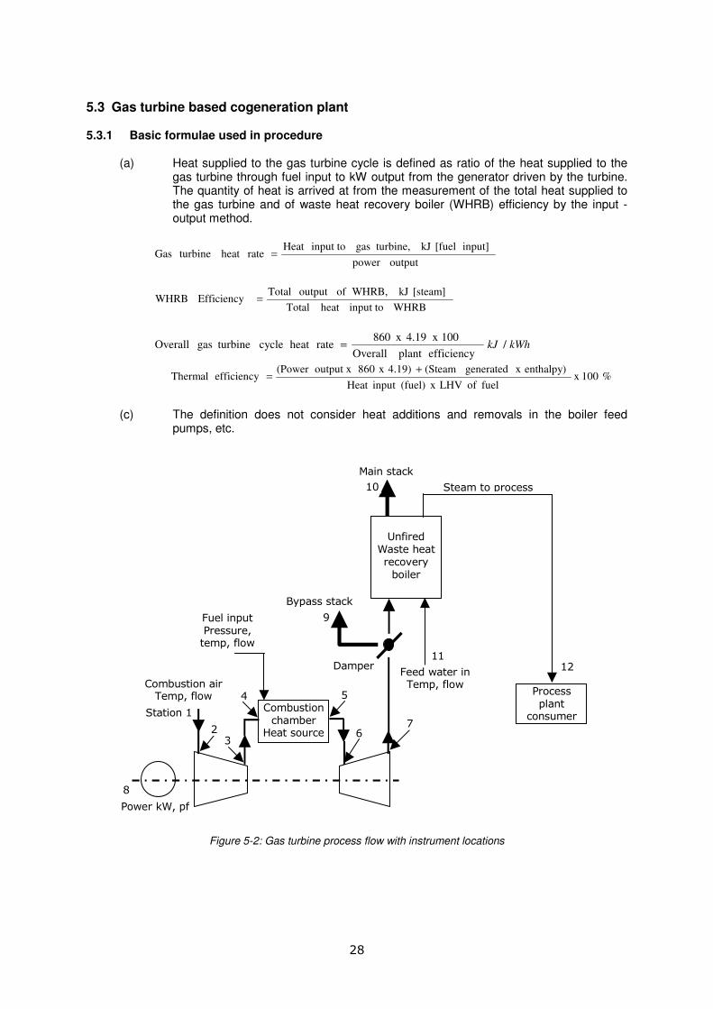
5.3 Gas turbine based cogeneration plant 5.3.1 Basic formulae used in procedure (a) Heat supplied to the gas turbine cycle is defined as ratio of the heat supplied to the
gas turbine through fuel input to kW output from the generator driven by the turbine. The quantity of heat is arrived at from the measurement of the total heat supplied to the gas turbine and of waste heat recovery boiler (WHRB) efficiency by the input - output method.
outputpower
input] [fuel kJ turbine,gas input toHeat rateheatturbineGas =
WHRBinput toheat Total
[steam] kJ WHRB,ofoutput TotalEfficiency WHRB =
kWhkJ /efficiencyplant Overall
100 x 4.19 x 860rateheat cycle turbinegas Overall =
% 100x fuel of LHV x (fuel)input Heat
enthalpy) x generated (Steam4.19) x 860output x (Power efficiency Thermal
+=
(c) The definition does not consider heat additions and removals in the boiler feed
pumps, etc.
Combustion chamber
Heat source
Unfired
Waste heat recovery boiler
Process plant
consumer
Feed water in Temp, flow
Main stack
Bypass stack
Fuel input Pressure, temp, flow
Combustion air Temp, flow
Power kW, pf
Damper
Steam to process
Station 1
2 3
4 5
6 7
8
9
10
11 12
Figure 5-2: Gas turbine process flow with instrument locations

29
5.3.2 Instrumentation requirements (a) Typical diagram showing the basic nomenclature used hereunder and location of
instruments for measuring various variables is given in Fig. 5.2. Some of the variables need to be estimated from the manufacturer’s data as indicated on the figure.
Station 1: Ambient air conditions, pressure, temperature, humidity, flow, pressure
drop across the air filter bank
Station 2: Conditions of air at inlet of compressor, temperature
Station 3: Conditions of air leaving the compressor (manufacturer’s data, if
required)
Station 4: Fuel input to combustion chamber, flow, temperature, pressure, analysis
(fuel supplier’s data or analysis through third party)
Station 5: Flue gas conditions at exit of combustion chamber, temperature
(manufacturer’s data, if required)
Station 6: Flue gas conditions at inlet of turbine, temperature (manufacturer’s data,
if required)
Station 7: Exhaust flue gas conditions leaving turbine, entering WHRB,
temperature, flow
Station 8: Power output, kW: Kilowatts, pf: Power factor
Station 9: Exhaust flue gas conditions leaving the bypass stack, temperature
Station 10: Exhaust flue gas conditions leaving the main stack, temperature
Station 11: Feed water input to WHRB, flow, temperature
Station 12: Steam output from WHRB, pressure, temperature, flow
Additional nomenclature used with letter designate the type of fluid in various parts of
cycle:
f : Fuel a : Air (or other working fluid)
wtr : Water g : Gas after the combustion chamber
s : Steam b : Bearing fluid
5.3.3 Operating conditions (a) The test fuel for gas turbine based cogeneration and test conditions can be decided
prior to the test.
(b) The test data for the system can be collected only after the steady state plant operating conditions have been established. Steady state is to be considered achieved when continuous monitoring indicates the readings have been within the maximum permissible variations.
(c) The time duration of test is to be minimum eight hours after attaining of steady state conditions.
(d) In the event of observance of inconsistency during conduct of a test, or during subsequent interpretation and analysis of the recorded data affecting the validity of results, an effort should be made to adjust or eliminate the inconsistency. In case of abnormal inconsistency, the entire test can be conducted again.
(e) Specific conditions for the testing of a waste heat recovery boiler (WHRB) can be as follows.
i. Heat input is total of the sensible heat and latent heat contents of hot flue gas entering WHRB and chemical heat combustion resulting from burning of supplementary fuel, if any.

30
ii. WHRB output can be determined following the procedure adopted for conventional fired boilers, i.e. heat absorbed by the working fluid. Another method can be to derive the steam flow as output from WHRB.
iii. Determination of heat content of hot flue gas entering WHRB will require measurement of temperature, weight flow of gas and analysis of gas for better accuracy of the result.
iv. Gas quantity entering the WHRB may be determined by the following methods.
(1) calculation of amount of fuel burnt in gas turbine, analysis of fuel and composition of waste gas.
(2) actual measurement of gas quantity.
(3) measurement of gas quantity leaving WHRB, analysis gases entering and leaving WHRB including calculating supplementary combustion products, if supplementary fuel is fired.
v. Losses in WHRB can vary with type of input to the prime mover.
vi. For WHRB without supplementary firing, the heat losses can be as follows.
(1) the difference between sensible heat content of exhaust flue gas at exit gas temperature and reference air temperature, usually ambient.
(2) the difference between latent heat content of exhaust flue gas at exit gas temperature and reference air temperature.
vii. Minimum test duration can be four hours from the achieving of the steady state condition.
5.3.4 Calculation procedure
(a) Fuel flow calculations Fuel flow can be measured using methods given in section 4.6.
(b) Specific fuel consumption calculations
Calculate the fuel consumption of the plant per unit time using following formulae.
fuelsgaseousforTt/VsVng = fuelsliquidforTt/WwWl =
Where, Vng = fuel consumption per hour, for gaseous fuels, Nm
3 /hr
Wl = fuel consumption per hour, for liquid fuels, kg/hr, Tt = time duration of test, hours
Vs = total gaseous fuel volume in Nm3
Ww = total liquid fuel consumption, kg Calculate the specific fuel consumption of the plant using following equation.
fuelsliquidfor P
W W fuelsgaseousfor
P
VW l
s
ng
s ==
Where, WS = specific fuel consumption, for gaseous fuels Nm
3
for liquid fuels kg/kWh P = net electrical power output, kW
(c) Heat consumption rate calculations Calculate the heat consumption rate of the plant using following equation.
fuelsgaseousforQxVq lonr g= fuelsliquidforQxWq lolr =
Where,

31
qr = rate of heat consumption, kJ/hr Qlo = lower heating value of fuel, for gaseous fuels kJ/Nm
3
for liquid fuels, kJ/kg,
(d) Heat rate calculations Calculate the heat rate of the plant using following equation.
P
qq r
s =
Where, qs = heat rate, kJ/kWh qr = rate of heat consumption, kJ/hr
P = net electrical power output, kW
OR heat rate of the plant may also be calculated using following equation.
kWpower,electricalnetforη
3600q
gt
s =
Where, qs = heat rate, kJ/kWh
ηgt = thermal efficiency based on net electrical power output OR the heat rate of the plant using following equation.
fuelsgaseousforP
QVq
ng
s
lox= fuelsliquidfor
P
QWq lol
s
x=
Where, qs = heat rate, kJ/kWh Qlo = lower heating value of fuel, for gaseous fuels kJ/Sm
3 or Nm
3
for liquid fuels kJ/kg, Vng = fuel consumption per hour, for gaseous fuels, Sm
3 or Nm
3/hr
Wl = fuel consumption per hour, for liquid fuels, kg/hr, P = net electrical power output kW
(e) Thermal efficiency calculations for gas turbine
r
gtq
100xPx3600η =
Where,
ηgt = thermal efficiency based on net electrical power output, percent P = net electrical power output kW
qr = rate of heat consumption, kJ/hr
(f) Thermal efficiency calculations for WHRB
( )
)t(txCxW
100xhhxWη
exhaustepeg
1112swhrb
−
−=
Where,
ηwhrb = thermal efficiency based on net steam output, percent Ws = steam rate, kg/sec h12 = steam enthalpy at boiler outlet, kJ/kg
Weg = exhaust gas flow rate, kg/sec Cp = average value of specific heat of exhaust gas, kJ/kg
0C
te = exhaust gas temperature at WHRB inlet, 0C
texhaust = Exhaust temperature at WHRB outlet, 0C
32
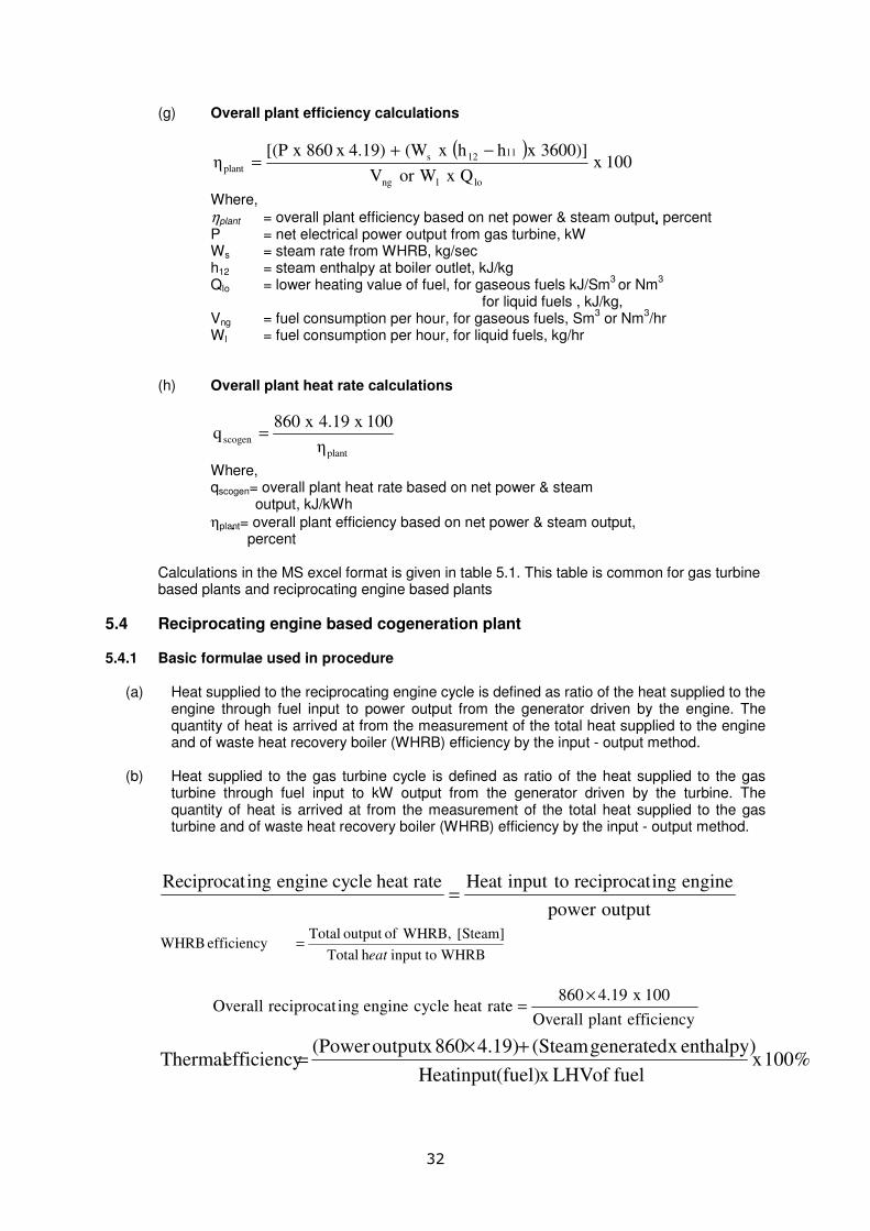
(g) Overall plant efficiency calculations
( )
100xQxWorV
3600)]xhhx(W4.19) x 860x[(Pη
lolng
1112s
plant
−+=
Where,
ηplant = overall plant efficiency based on net power & steam output, ������������������������������������������������percent P = net electrical power output from gas turbine, kW Ws = steam rate from WHRB, kg/sec h12 = steam enthalpy at boiler outlet, kJ/kg
Qlo = lower heating value of fuel, for gaseous fuels kJ/Sm3 or Nm
3
for liquid fuels , kJ/kg, Vng = fuel consumption per hour, for gaseous fuels, Sm
3 or Nm
3/hr
Wl = fuel consumption per hour, for liquid fuels, kg/hr
(h) Overall plant heat rate calculations
plant
scogenη
100x19.4x860q =
Where, qscogen= overall plant heat rate based on net power & steam output, kJ/kWh
ηplant = overall plant efficiency based on net power & steam output, percent
Calculations in the MS excel format is given in table 5.1. This table is common for gas turbine
based plants and reciprocating engine based plants
5.4 Reciprocating engine based cogeneration plant 5.4.1 Basic formulae used in procedure (a) Heat supplied to the reciprocating engine cycle is defined as ratio of the heat supplied to the
engine through fuel input to power output from the generator driven by the engine. The quantity of heat is arrived at from the measurement of the total heat supplied to the engine and of waste heat recovery boiler (WHRB) efficiency by the input - output method.
(b) Heat supplied to the gas turbine cycle is defined as ratio of the heat supplied to the gas
turbine through fuel input to kW output from the generator driven by the turbine. The quantity of heat is arrived at from the measurement of the total heat supplied to the gas turbine and of waste heat recovery boiler (WHRB) efficiency by the input - output method.
outputpower
engineingreciprocattoinputHeatrateheat cycle engineingReciprocat=
WHRBtoinputhTotal
[Steam]WHRB,ofoutputTotalefficiencyWHRB
eat=
efficiencyplantOverall
100x4.19860rateheatcycleengine ingreciprocatOverall
×=
%100xfuelofLHVx(fuel)inputHeat
enthalpy)xgenerated (Steam4.19)860xoutput(PowerefficiencyThermal
+×=

33
(b) The definition does not consider heat additions and removals in boiler feed pumps, or hot water pumps, etc. as the case may be.
5.4.2 Instrumentation requirements (a) Typical diagram showing the basic nomenclature used hereunder and location of
instruments for measuring various variables is given in Fig. 5.3. Some of the variables can be estimated from the manufacturer’s data as indicated on the figure.
Unfired
Waste heat recovery
boiler
Process plant
consumer
Feed water in Temp, flow
Main stack
Bypass stack
Fuel input Pressure, temp, flow
Combustion air Temp, flow
Power kW, pf
Damper
Steam to process
Station 1
2
3
6
4
8
5
7
9 10
Flywheel
Reciprocating engine
Lube-oil pressure, temp
Exhaust gas
Generator
Figure 5-3: Reciprocating Engine process flow with instrument locations
Station 1 : Ambient air conditions, pressure, temperature, humidity
Station 2 : Fuel input to engine, flow, temperature, pressure, analysis
Station 3 : Conditions for lube-oil sent to engine, analysis, flow, temperature, pressure
Station 4 : Flue gas conditions at exit of engine, temperature
Station 5 : Exhaust flue gas conditions leaving the bypass stack, temperature
Station 6 : Exhaust flue gas conditions entering WHRB, temperature
Station 7 : Exhaust flue gas conditions leaving the main stack, temperature
Station 8 : Power output, kW: Kilowatts, pf: Power factor
Station 9 : Feed water input to WHRB, flow, temperature
Station 10: Steam output from WHRB, pressure, temperature, flow
Additional nomenclature used with letter designate the type of fluid in various parts of cycle:
f : Fuel a : Air (or other working fluid)
w : Water g : Gas after the combustion chamber
s : Steam b : Bearing fluid

34
5.4.3 Operating conditions
(a) The test data for the system are to be collected only after the steady state plant operating
conditions have been established. Steady state can be considered achieved when continuous monitoring indicates that the readings have been within the maximum permissible variations.
(b) The time duration of test can be minimum eight hours after attaining steady state
conditions.
(c) In the event of observance of inconsistency during conduct of a test, or during subsequent interpretation and analysis of the recorded data affecting the validity of results, an effort can be made to adjust or eliminate the inconsistency. In case of abnormal inconsistency, the entire test can be conducted again.
(d) Specific conditions for the testing of a waste heat recovery boiler (WHRB) can be as
provided in Para 5.3.3(g). 5.4.4 Calculation procedure
(a) Fuel flow calculations
i. Gaseous fuels – Method as provided in section 4.6 can be followed for determining the flow of gaseous fuel.
ii. Liquid fuels – For measurement of liquid fuel flow and quantity, the procedure at section 4.6 can be employed.
(b) Fuel heating value calculations As explained in section 4.13.
(c) Specific fuel consumption calculations
Calculate the fuel consumption of the plant per unit time using following formulae.
Wng = Vs/ Tt, for gaseous fuels Wl = Ww/ Tt, for liquid fuels, Where,
Vng = fuel consumption per hour, for gaseous fuels, Nm3, Sm
3/hr
Wl = fuel consumption per hour, for liquid fuels, kg/hr, Tt = time duration of test, hours
Vs = total gaseous fuel volume in standard m3
Ww = total liquid fuel consumption, kg Calculate the specific fuel consumption of the plant using following equation.
fuelsliquidfor P
W W fuelsgaseousfor
P
VW l
s
ng
s ==
Where, WS = specific fuel consumption, for gaseous fuels Nm
3 or Sm
3/kWh
for liquid fuels kg/kWh P = net electrical power output, kW
(d) Heat consumption rate calculations Calculate the heat consumption rate of the plant using following equation.
fuelsgaseousforQxVq lonr g=
fuelsliquidforQxWq lolr =
Where,

35
qr = rate of heat consumption, kJ/hr Qlo = lower heating value of fuel, for gaseous fuels kJ/Nm
3 or Sm
3
for liquid fuels ,kJ/kg,
(e) Heat rate calculations Calculate the heat rate of the plant using following equation.
P
qq r
s =
Where, qs = heat rate, kJ/kWh qr = rate of heat consumption, kJ/hr P = net electrical power output kW
OR heat rate of the plant may also be calculated using following equation.
kWinpowerelectricalnetforη
3600q
re
s =
Where, qs = heat rate, kJ/kWh re = thermal efficiency based on net electrical power output
OR the heat rate of the plant using following equation.
fuelgaseousforP
QxVq 0lng
s = fuelliquidforP
QxWq 0ll
s =
Where, qs = heat rate, kJ/kWh Ql0 = lower heating value of fuel, for gaseous fuels kJ/Sm
3 or Nm
3
for liquid fuels kJ/kg, Vng = fuel consumption per hour, for gaseous fuels, Sm
3 or Nm
3/hr
Wl = fuel consumption per hour, for liquid fuels, kg/hr, P = net electrical power output kW
(f) Thermal efficiency calculations for reciprocating engine
r
req
100xPx3600η =
Where,
ηre = thermal efficiency based on net electrical power output, percent P = net electrical power output kW
qr = rate of heat consumption, kJ/hr
(g) Thermal efficiency calculations for WHRB
( )
) t- (t x C x W
100 x hh x Wη
exhaustepeg
1011swhrb
−=
Where,
ηwhrb = thermal efficiency based on net steam output, % Ws = steam rate, kg/sec h11 = steam enthalpy at boiler outlet, kJ/kg
Weg = exhaust gas flow rate, kg/sec Cp = average value of specific heat of exhaust gas, kJ/kg
0C
te = exhaust gas temperature at WHRB inlet, 0C

36
texhaust = Exhaust temperature at WHRB outlet, 0C
(h) Overall plant efficiency calculations
( )
lolng
1011s
plantQ x or W W
100 x 3600)] x hh x (W 4.19) x 860 x [(Pη
−+=
Where,
ηplant = overall plant efficiency based on net power & steam output, % P = net electrical power output from gas turbine, kW Ws = steam rate from WHRB, kg/sec h11 = steam enthalpy at boiler outlet, kJ/kg
Qlo = lower heating value of fuel, for gaseous fuels – kJ/Sm3 or Nm
3
for liquid fuels - kJ/kg, Wng = fuel consumption per hour, for gaseous fuels, Sm
3 or Nm
3/hr
Wl = fuel consumption per hour, for liquid fuels, kg/hr,
(j) Overall plant heat rate calculations
plant
scogenη
x1004.19x860q =
Where, qscogen = overall plant heat rate based on net power & steam output, kJ/kWh
ηplant = overall plant efficiency based on net power & steam output, % The following table summarises calculations for estimating overall efficiency of reciprocating
engine based cogeneration plants and gas turbine based plants.
Table 5-2: Calculations for estimating overall efficiency and heat rate
Sl
No.
Parameter Equation to be used in column C & Comments Quantity
A B C
1 Vg, fuel consumption rate, Sm3/h Measured value
2 P, electrical power output, kW Measured value
3 Qlo, lower heating value of fuel, kJ/ m3 From standard data
4 qr, rate of heat consumption, kJ/h C1*C3
5 qs , heat rate, kJ/kWh C4/C2
6 ηg, thermal efficiency based on net electrical
power output, %
3600 X C2 X 100 / C5
7 Weg, exhaust gas flow rate, kg/s Estimated value
8 Cp, average value of specific heat of exhaust
gas, kJ/kg-0C
From standard data
9 te, exhaust gas temperature at WHRB inlet, 0C Measured value
10 tpp, pinch point temperature, 0C specified value
11 h10, feed water enthalpy at drum inlet, kJ/kg From measured temperature & standard data
12 h11, steam enthalpy at boiler outlet, kJ/kg From measured temperature & standard data
13 Ws, steam rate from WHRB, kg/sec Measured value
14 texhaust, temperature at WHRB exit (chimney), 0C
Measured value
15 ηwhrb thermal efficiency of WHRB based on net
steam output
C13*(C12-C11)*100/(C7*C8* (C9-C14))
16 ηplantoverall plant efficiency based on net
power & steam output, %
((C2*860*4.19)+(C13*(C12-C11)*1000)) /C4
17 qscogenoverall plant heat rate based on net
power & steam output, kJ/kWh
860*4.19*100/C16
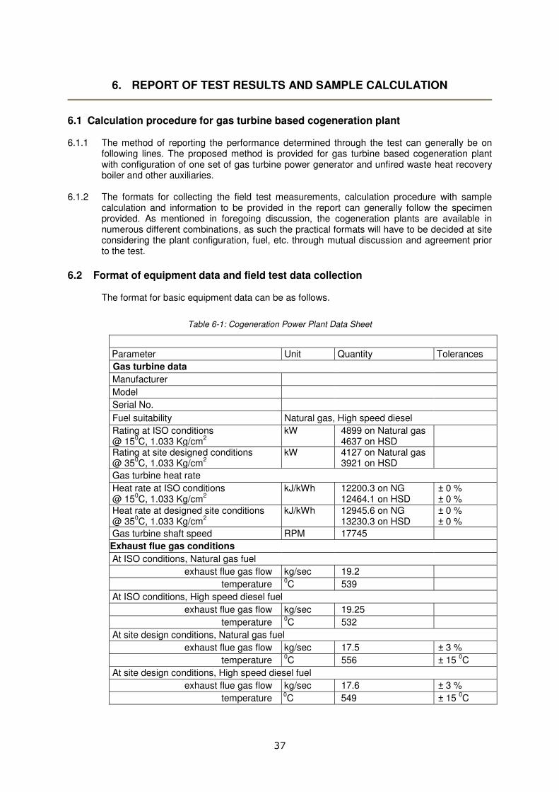
37
6. REPORT OF TEST RESULTS AND SAMPLE CALCULATION
6.1 Calculation procedure for gas turbine based cogeneration plant 6.1.1 The method of reporting the performance determined through the test can generally be on
following lines. The proposed method is provided for gas turbine based cogeneration plant with configuration of one set of gas turbine power generator and unfired waste heat recovery boiler and other auxiliaries.
6.1.2 The formats for collecting the field test measurements, calculation procedure with sample
calculation and information to be provided in the report can generally follow the specimen provided. As mentioned in foregoing discussion, the cogeneration plants are available in numerous different combinations, as such the practical formats will have to be decided at site considering the plant configuration, fuel, etc. through mutual discussion and agreement prior to the test.
6.2 Format of equipment data and field test data collection
The format for basic equipment data can be as follows.
Table 6-1: Cogeneration Power Plant Data Sheet
Parameter Unit Quantity Tolerances
Gas turbine data
Manufacturer
Model
Serial No.
Fuel suitability Natural gas, High speed diesel
Rating at ISO conditions @ 15
0C, 1.033 Kg/cm
2
kW
4899 on Natural gas 4637 on HSD
Rating at site designed conditions @ 35
0C, 1.033 Kg/cm
2
kW
4127 on Natural gas 3921 on HSD
Gas turbine heat rate
Heat rate at ISO conditions @ 15
0C, 1.033 Kg/cm
2
kJ/kWh
12200.3 on NG 12464.1 on HSD
± 0 % ± 0 %
Heat rate at designed site conditions @ 35
0C, 1.033 Kg/cm
2
kJ/kWh
12945.6 on NG 13230.3 on HSD
± 0 % ± 0 %
Gas turbine shaft speed RPM 17745
Exhaust flue gas conditions
At ISO conditions, Natural gas fuel
exhaust flue gas flow kg/sec 19.2
temperature 0C 539
At ISO conditions, High speed diesel fuel
exhaust flue gas flow kg/sec 19.25
temperature 0C 532
At site design conditions, Natural gas fuel
exhaust flue gas flow kg/sec 17.5 ± 3 %
temperature 0C 556 ± 15
0C
At site design conditions, High speed diesel fuel
exhaust flue gas flow kg/sec 17.6 ± 3 %
temperature 0C 549 ± 15
0C

38
Cogeneration Power Plant Data Sheet
Parameter Unit Quantity Tolerances
Natural gas fuel Data
Higher heating value kJ/SM3 40821.3 ± 1 %
Lower heating value kJ/SM3 39447.6 ± 1 %
High speed diesel fuel Data
Higher heating value kJ/kg 44589.0 ± 2 %
Lower heating value kJ/kg 42705.4 ± 2 %
Generator data
Manufacturer
Model
Serial No.
Rating for apparent power kVA 5200
Power output at rated power factor kW 4160 ± 3 %
Generation nominal voltage kV 11
Full load current (at rated pf) Amp 273.25
Rated power factor 0.8
Generator shaft speed RPM 1500
Waste heat recovery boiler data
Manufacturer
Model
Serial No.
Rated steam conditions
MCR steam flow kg/hour 10450 ± 5 %
pressure Kg/cm2(g) 8.0
temperature 0C 200
Exhaust flue gas conditions at WHRB outlet
temperature 0C 135 ± 3 %
Exhaust gas pressure drop between turbine and WHRB inlet
mm Wc 100
Exhaust gas pressure drop between WHRB inlet and chimney
mm Wc 250
The format for presentation of collected test data for report and for using in the calculations can be as follows.
Description
Parameter Unit Quantity
Test duration hours 4
Ambient conditions (Gas turbine compressor inlet conditions)
air temperature 0C 36.5
pressure kg/cm2 1.0332
relative humidity % 57.5
Gas turbine data
Gas turbine compressor inlet conditions
air temperature 0C 37.0
pressure kg/cm2 1.0332
dry bulb temperature 0C 36.5
wet bulb temperature 0C 28.0
Diff. Pressure - Inlet air filter mm Wc 35.8
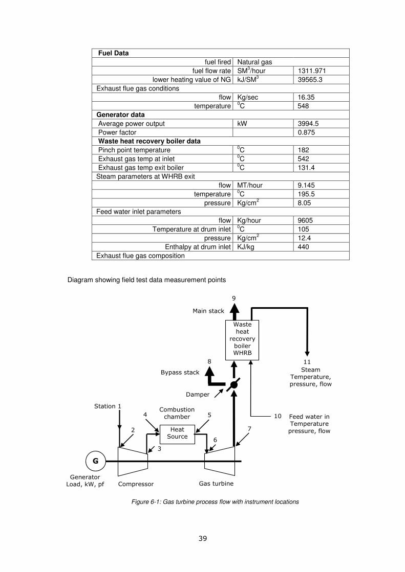
39
Fuel Data
fuel fired Natural gas
fuel flow rate SM3/hour 1311.971
lower heating value of NG kJ/SM3 39565.3
Exhaust flue gas conditions
flow Kg/sec 16.35
temperature 0C 548
Generator data
Average power output kW 3994.5
Power factor 0.875
Waste heat recovery boiler data
Pinch point temperature 0C 182
Exhaust gas temp at inlet 0C 542
Exhaust gas temp exit boiler 0C 131.4
Steam parameters at WHRB exit
flow MT/hour 9.145
temperature 0C 195.5
pressure Kg/cm2 8.05
Feed water inlet parameters
flow Kg/hour 9605
Temperature at drum inlet 0C 105
pressure Kg/cm2 12.4
Enthalpy at drum inlet KJ/kg 440
Exhaust flue gas composition
Diagram showing field test data measurement points
G
Heat Source
Waste heat
recovery boiler WHRB
Station 1
2
4
3
5
6
7
8
9
10
11
Generator Load, kW, pf
Compressor Gas turbine
Main stack
Bypass stack
Damper
Combustion chamber
Feed water in Temperature pressure, flow
Steam Temperature, pressure, flow
Fig. 5.2 – Gas turbine cycle process flow with instrument locations
Figure 6-1: Gas turbine process flow with instrument locations

40
Station 1: Ambient air conditions, pressure, temperature, humidity
Station 2: Air conditions at inlet of compressor,
Station 3: Conditions for air leaving comp
Station 4: Fuel input to combustion chamber, flow, temperature, pressure, analysis
Station 5: Flue gas conditions at exit of combustion chamber, temperature
Station 6: Flue gas conditions at inlet of turbine, temperature
Station 7: Exhaust flue gas conditions leaving turbine, entering WHRB, temperature, flow
Station 8: Exhaust flue gas conditions leaving the bypass stack, temperature
Station 9: Exhaust flue gas conditions leaving the main stack, temperature
Station 10: Feed water input to WHRB, flow, temperature
Station 11: Steam output from WHRB, pressure, temperature, flow
kW: Kilowatts pf: Power factor
Additional nomenclature used with letter designate the type of fluid in various parts of cycle:
f : Fuel a : Air (or other working fluid)
w : Water g : Gas after the combustion chamber
s : Steam b : Bearing fluid
6.3 Fuel flow calculations 6.4.1 The sample calculations consider firing of Natural gas fuel. It is assumed that for measuring
gas fuel flow and consumption, the digital readout is available on a control panel display unit
of equipment being fired with gas fuel. The readout on the control panel is available from a
microprocessor, which is fed necessary signals from the flow measuring device installed in
the field consisting of orifice, differential pressure transmitter and temperature transmitter
(duly compensated). The gas flow and consumption at 10 min. interval is noted for the test
duration and then averaged out for use in calculations.
6.4.2 The fuel higher heating value (HHV) and lower heating value (LLV) are averaged out on the
basis of the report of analysis generated by testing of sample of Natural gas prior to the
commencement of test and the heating values available from the supplier’s bills for the last 6-
12 months. The bills provide required data for considering the variations in the heating values
over a period of time to determine the best feasible value for the purpose of calculations.
6.4 Determination of Efficiency and Heat rate
6.5.1 fuelgaseousforP
VW
ng
s =
Where
Vng, fuel consumption per hour = 1311.971 Sm3/hr, for gaseous fuel
P, electrical power output kW = 3994.5 kW
Ws, specific fuel consumption = 1311.971/3994.5
= 0.32844 Sm3/kWh
6.5.2 Heat consumption rate calculations
Calculate the heat consumption rate of the plant using following equation.
fuelsgaseousforQxVq longr =
Where,
qr = rate of heat consumption, kJ/hr
Qlo, lower heating value of fuel, for gaseous fuels = 39565.3 kJ/Sm3
Vng, fuel consumption per hour = 1311.971 Sm3/hr, for gaseous fuel

41
qr = 1311.971 X 39565.3 kJ/hr
qr = 51.9085 million kJ/hr
6.5.3 Heat rate calculations
Calculate the heat rate of the plant using following equation.
P
qq r
s =
Where,
qs = heat rate, kJ/kWh
qr, rate of heat consumption = 51.9085 kJ/hr
P, net electrical power output = 3994.5 kW
qs, heat rate = 51.9085 X 10⁶ / 3994.5
= 12995 kJ/kWh
6.5.4 Gas turbine thermal efficiency calculations
r
gtq
100P3600η
×=
x
Where,
ηgt = thermal efficiency based on net electrical power output, percent
P, net electrical power output = 3994.5 kW
qr, rate of heat consumption = 51.9085 kJ/hr
ηgt = 3600 X P X 100 / qr
= 3600 X 3994.5 X 100 / 51.9085
= 27.7 %
Alternate formulae for heat rate of the plant may be used for calculating the gas turbine
efficiency as per following equation.
kWinpowerelectricalnetforη
3600qrate,heatturbineGas
gt
s =
Where,
qs, = heat rate, kJ/kWh
ηgt thermal efficiency based on net electrical power output = 27.7 %
qs, = 3600 X 100 / 27.7
heat rate = 12996 kJ/kWh
6.5.5 Steam flow from WHRB
Actual steam flow measured, average for 4 hours = 10.44 MT
= 2.9 kg/s
6.5.6 Thermal efficiency calculations for WHRB
( ))t(txCxW
100xhhxWη
exhaustepeg
11swhrb
−
−=
12
Where,
ηwhrb = thermal efficiency based on net steam output, percent
Ws, steam rate = 2.9 kg/sec

42
h11, steam enthalpy at boiler outlet = 2835.6 kJ/kg
Weg, exhaust gas flow rate = 16.25 kg/sec
Cp, average value of specific heat of exhaust gas = 1.1807 kJ/kg0C
te, exhaust gas temperature from GT = 542 0C
texhaust, temperature at WHRB exit (chimney) = 131.4 0C
( )
).(x.x.
x.x.ηwhrb
4131542180712516
1004406283592
−
−=
�� ηwhrb thermal efficiency based on net steam output = 87.7% percent
6.5.7. Overall plant efficiency calculations for gas turbine based cogeneration Plant
( )100x
QxV
3600)]xhhx(W4.19)860x[(Pη
long
11splant
12−+×=
Where,
ηplant = overall plant efficiency based on net power & steam output, percent
P, net electrical power output from gas turbine = 3994.5 kW
Ws, steam rate from WHRB = 2.9 kg/sec
h11, steam enthalpy at boiler outlet = 2835.6 kJ/kg
Qlo, lower heating value of fuel, for gaseous fuels = 39565.3 kJ/Sm3
Vng, fuel consumption per hour = 1311.971 Sm3/hr, for gaseous fuel
( )
1003395659711311
3600440628359219486053994x
.x.
)]x.x.().x.[(ηplant
−+×=
ηplant overall plant efficiency based on net power & steam output = 75.9%
6.5.8 Overall cogen plant heat rate calculations for gas turbine based system
plant
scogenη
100x4.19x860q =
Where,
qscogen = overall plant heat rate based on net power & steam output, kJ/kWh
ηplant overall plant efficiency based on net power & steam output = 75.9 %
975
100194860
.
x.xqscogen =
qscogen overall plant heat rate based = 4747.7 kJ/kWh on net power & steam output
The above calculations are summarized in the table given below, in MS Excel spread sheet
format.
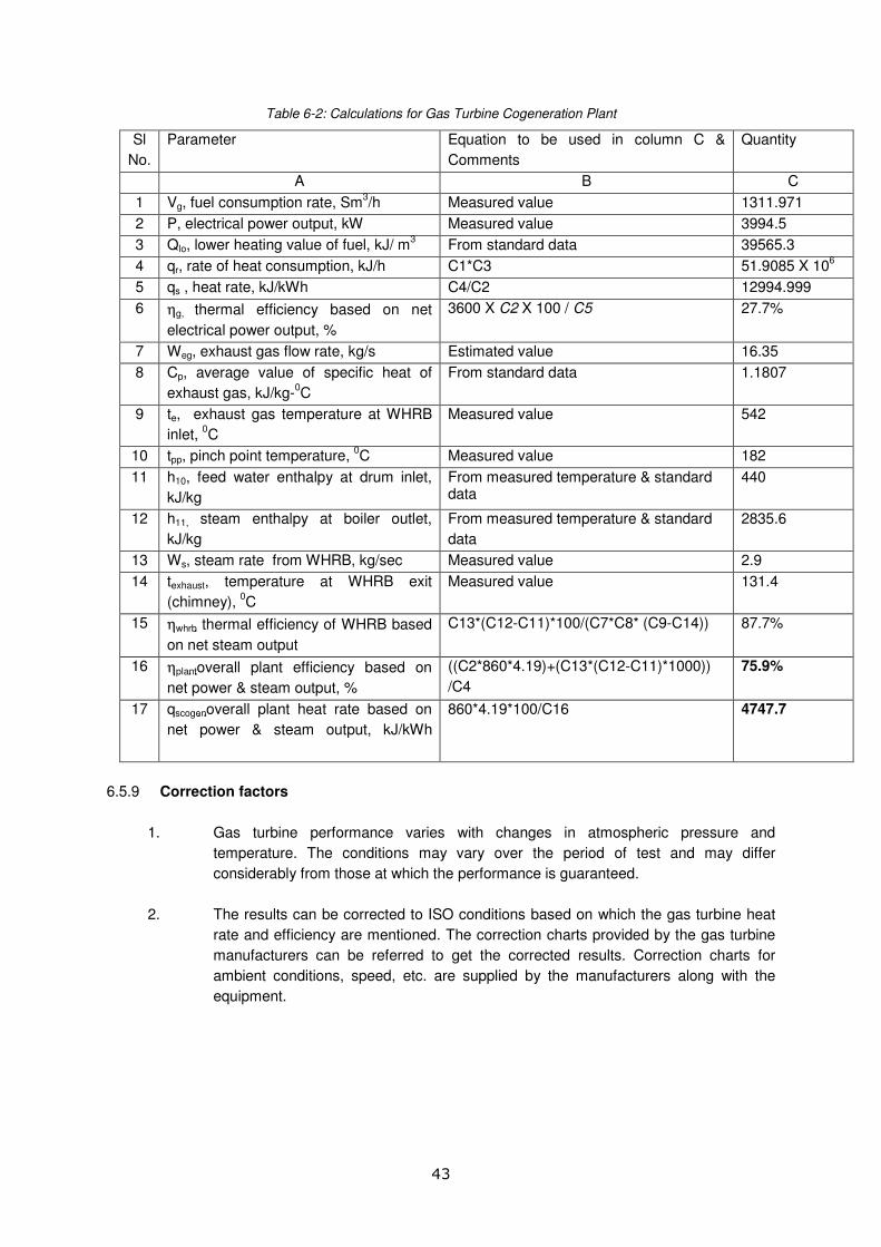
43
Table 6-2: Calculations for Gas Turbine Cogeneration Plant
Sl
No.
Parameter Equation to be used in column C &
Comments
Quantity
A B C
1 Vg, fuel consumption rate, Sm3/h Measured value 1311.971
2 P, electrical power output, kW Measured value 3994.5
3 Qlo, lower heating value of fuel, kJ/ m3 From standard data 39565.3
4 qr, rate of heat consumption, kJ/h C1*C3 51.9085 X 10⁶
5 qs , heat rate, kJ/kWh C4/C2 12994.999
6 ηg, thermal efficiency based on net
electrical power output, %
3600 X C2 X 100 / C5
27.7%
7 Weg, exhaust gas flow rate, kg/s Estimated value 16.35
8 Cp, average value of specific heat of
exhaust gas, kJ/kg-0C
From standard data 1.1807
9 te, exhaust gas temperature at WHRB
inlet, 0C
Measured value 542
10 tpp, pinch point temperature, 0C Measured value 182
11 h10, feed water enthalpy at drum inlet,
kJ/kg
From measured temperature & standard data
440
12 h11, steam enthalpy at boiler outlet,
kJ/kg
From measured temperature & standard
data
2835.6
13 Ws, steam rate from WHRB, kg/sec Measured value 2.9
14 texhaust, temperature at WHRB exit
(chimney), 0C
Measured value 131.4
15 ηwhrb thermal efficiency of WHRB based
on net steam output
C13*(C12-C11)*100/(C7*C8* (C9-C14)) 87.7%
16 ηplant overall plant efficiency based on
net power & steam output, %
((C2*860*4.19)+(C13*(C12-C11)*1000))
/C4
75.9%
17 qscogenoverall plant heat rate based on
net power & steam output, kJ/kWh
860*4.19*100/C16 4747.7
6.5.9 Correction factors
1. Gas turbine performance varies with changes in atmospheric pressure and
temperature. The conditions may vary over the period of test and may differ
considerably from those at which the performance is guaranteed.
2. The results can be corrected to ISO conditions based on which the gas turbine heat
rate and efficiency are mentioned. The correction charts provided by the gas turbine
manufacturers can be referred to get the corrected results. Correction charts for
ambient conditions, speed, etc. are supplied by the manufacturers along with the
equipment.

44
7. UNCERTAINTY ANALYSIS
7.1 Introduction Uncertainty denotes the range of error, i.e. the region in which one guesses the error to be.
The purpose of uncertainty analysis is to use information in order to quantify the amount of
confidence in the result. The uncertainty analysis tells us how confident one should be in the
results obtained from a test.
Guide to the Expression of Uncertainty in Measurement (or GUM as it is now often called)
was published in 1993 (corrected and reprinted in 1995) by ISO. The focus of the ISO Guide
or GUM is the establishment of "general rules for evaluating and expressing uncertainty in
measurement that can be followed at various levels of accuracy “.
The following methodology is a simplified version of estimating combined uncertainty at field
conditions, based on GUM.
7.2 Methodology Uncertainty is expressed as X +/- y where X is the calculated result and y is the estimated
standard deviation. As instrument accuracies are increased, y decreases thus increasing the
confidence in the results.
A calculated result, r, which is a function of measured variables X1, X2, X3,….., Xn can be
expressed as follows:
r = f(X1, X2, X3,….., Xn) The uncertainty for the calculated result, r, is expressed as
5.02
3
3
2
2
2
2
1
1
.......
+
×
∂
∂+
×
∂
∂+
×
∂
∂=∂ x
X
rx
X
rx
X
rr δδδ ----(1)
Where:
r∂ = Uncertainty in the result
xiδ = Uncertainties in the measured variable iX
iX
r
∂
∂ = Absolute sensitivity coefficient
In order to simplify the uncertainty analysis, so that it can be done on simple spreadsheet
applications, each term on RHS of the equation-(1) can be approximated by:
1X
r
∂
∂x ∂X1 = r(X1+∂X1) – r(X1) ----(2)
The basic spreadsheet is set up as follows, assuming that the result r is a function of the four
parameters X1, X2, X3 & X4. Enter the values of X1, X2, X3 & X4 and the formula for calculating
r in column A of the spreadsheet. Copy column A across the following columns once for
every variable in r (see table 7.1). It is convenient to place the values of the uncertainties
∂(X1), ∂(X2) and so on in row 1 as shown.
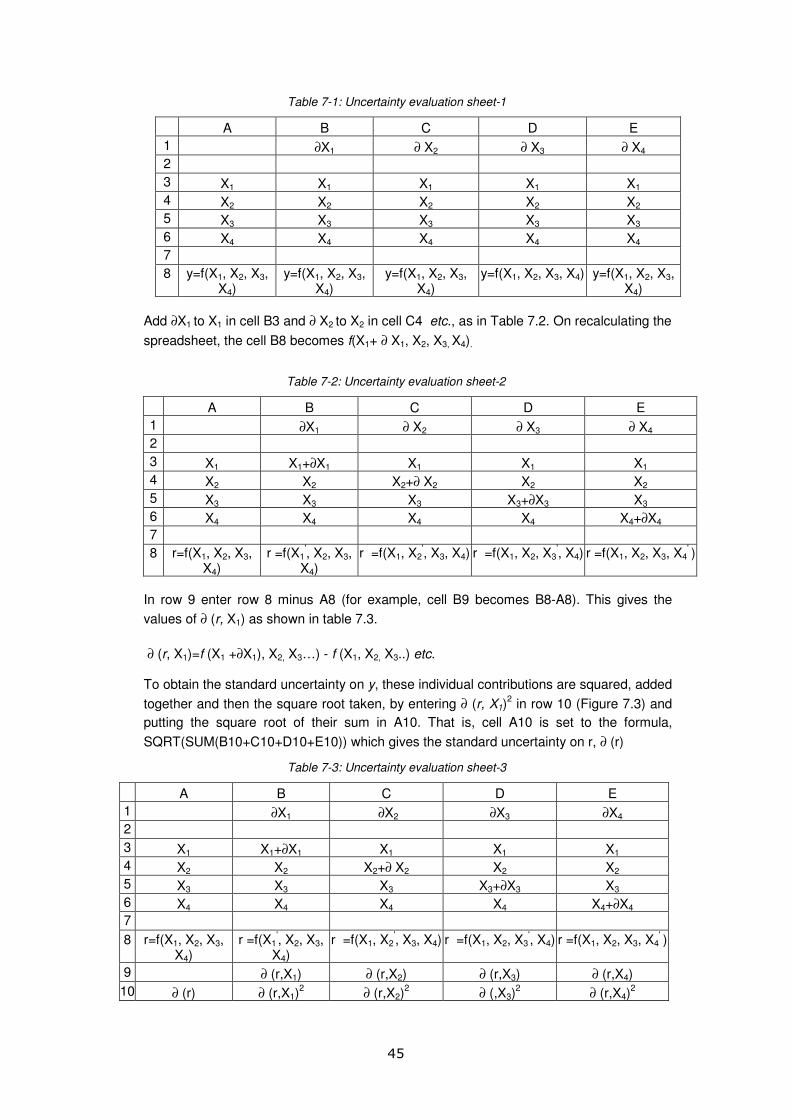
45
Table 7-1: Uncertainty evaluation sheet-1
A B C D E
1 ∂X1 ∂ X2 ∂ X3 ∂ X4
2
3 X1 X1 X1 X1 X1
4 X2 X2 X2 X2 X2
5 X3 X3 X3 X3 X3
6 X4 X4 X4 X4 X4
7
8 y=f(X1, X2, X3, X4)
y=f(X1, X2, X3, X4)
y=f(X1, X2, X3, X4)
y=f(X1, X2, X3, X4) y=f(X1, X2, X3, X4)
Add ∂X1 to X1 in cell B3 and ∂ X2 to X2 in cell C4 etc., as in Table 7.2. On recalculating the
spreadsheet, the cell B8 becomes f(X1+ ∂ X1, X2, X3, X4).
Table 7-2: Uncertainty evaluation sheet-2
A B C D E
1 ∂X1 ∂ X2 ∂ X3 ∂ X4
2
3 X1 X1+∂X1 X1 X1 X1
4 X2 X2 X2+∂ X2 X2 X2
5 X3 X3 X3 X3+∂X3 X3
6 X4 X4 X4 X4 X4+∂X4
7
8 r=f(X1, X2, X3, X4)
r =f(X1', X2, X3,
X4) r =f(X1, X2
', X3, X4) r =f(X1, X2, X3
', X4) r =f(X1, X2, X3, X4
' )
In row 9 enter row 8 minus A8 (for example, cell B9 becomes B8-A8). This gives the
values of ∂ (r, X1) as shown in table 7.3.
∂ (r, X1)=f (X1 +∂X1), X2, X3…) - f (X1, X2, X3..) etc. To obtain the standard uncertainty on y, these individual contributions are squared, added
together and then the square root taken, by entering ∂ (r, X1)2 in row 10 (Figure 7.3) and
putting the square root of their sum in A10. That is, cell A10 is set to the formula,
SQRT(SUM(B10+C10+D10+E10)) which gives the standard uncertainty on r, ∂ (r)
Table 7-3: Uncertainty evaluation sheet-3
A B C D E
1 ∂X1 ∂X2 ∂X3 ∂X4
2
3 X1 X1+∂X1 X1 X1 X1
4 X2 X2 X2+∂ X2 X2 X2
5 X3 X3 X3 X3+∂X3 X3
6 X4 X4 X4 X4 X4+∂X4
7
8 r=f(X1, X2, X3, X4)
r =f(X1', X2, X3,
X4) r =f(X1, X2
', X3, X4) r =f(X1, X2, X3
', X4) r =f(X1, X2, X3, X4
' )
9 ∂ (r,X1) ∂ (r,X2) ∂ (r,X3) ∂ (r,X4)
10 ∂ (r) ∂ (r,X1)2 ∂ (r,X2)
2 ∂ (,X3)
2 ∂ (r,X4)
2

46
7.3 Uncertainty Evaluation of Cogeneration Plant Efficiency Testing
Based on above discussions, the methodology for estimating uncertainty in efficiency testing
of cogeneration plants is explained below.
The instrument accuracy table is developed based on the accuracy of the instruments from
calibration certificates. It should be noted that all instruments used in testing a cogeneration
plants should be calibrated in the operating range and obtain a calibration curve. This helps in
understanding errors at various points. If an instrument is tested at full scale value only, the
absolute value uncertainty in measurements will increase.
For example, for a temperature indicator having 0.5% error and 1000 ºC full scale value, If
calibration curve is not available, the absolute error will be based on full scale value, i.e. 1000
x 0.5% = 5ºC. Thus, uncertainty in temperature measurement is ±5 ºC. A measurement of
100ºC with this meter will be indicated as 100 ±5 ºC i.e. 5% error.
If the instrument is calibrated and assuming that error at the measured value of 500 ºC is
0.5% from the calibration curve. The absolute error at this point can be 0.005 x 500 = 2.5 ºC.
Thus, uncertainty in voltage measurement is ±2.5 ºC.
In table 7.4, uncertainties in measurements are given as a % of measured value based on
calibration curve for each instrument.
Table 7-4: Instrument accuracy table
δwg δP δweg δΤe δΤpp δΤexh
Instrument accuracy
2% 0.5% 2.0% 0.5% 0.5% 0.5%
Absolute accuracy 26.24 20.0 0.327 2.71 0.91 0.657
The measurements and estimation of uncertainties are given in Table 7.5.

47
Table 7-5: Measurements and Uncertainty analysis
δwg δP δweg δΤe δΤpp δΤexh
Instrument accuracy 2% 0.5% 2.0% 0.5% 0.5% 0.5%
Absolute accuracy 26.24 20.0 0.327 2.71 0.91 0.657
Measured Parameters Unit Symbol Measurements wg + δwg P+δP weg + δweg Te + δTe Tpp + δTpp Texh + δTexh
Fuel consumption m3/hr wg 1311.971 1338.21 1311.971 1311.971 1311.971 1311.971 1311.971
Electrical Power output kW P 3994.5 3994.5 4014.5 3994.5 3994.5 3994.5 3994.5
Exhaust gas flow rate at WHRB kg/s weg 16.35 16.35 16.35 16.677 16.35 16.35 16.35
Exhaust gas temperature at WHRB inlet C Te 542 542 542 542 544.71 542 542
Pinchpoint temperature C Tpp 182 182 182 182 182 182.91 182
Temperature at WHRB exhaust C Texhaust 131.4 131.4 131.4 131.4 131.4 131.4 132.057
Values taken from tables/graphs/assumptions
Lower heating value of fuel kJ/m3 Qlo 39565.3 39565.3 39565.3 39565.3 39565.3 39565.3 39565.3
Specific heat of exhaust gas kJ/kg-C Cp 1.18 1.18 1.18 1.18 1.18 1.18 1.18
Feed water enthalpy at drum inlet kJ/kg h10 440 440 440 440 440 440 440
Steam enthalpy at boiler outlet kJ/kg h11 2835.6 2835.6 2835.6 2835.6 2835.6 2835.6 2835.6
Results
Steam flow rate kg/s ws 2.90 2.90 2.90 2.96 2.92 2.89 2.90
Heat consumption rate kJ/hr qr 51908526.21 52946696.73 51908526.21 51908526.21 51908526.21 51908526.21 51908526.21
Heat rate kJ/kWh qs 12995.00 13254.90 12930.35 12995.00 12995.00 12995.00 12995.00
Gas Turbine thermal efficiency % ηGT 26.3% 25.7% 26.4% 26.3% 26.3% 26.3% 26.3%
Thermal efficiency of WHRB % ηwhrb 87.7% 87.7% 87.7% 87.7% 87.8% 87.5% 87.8%
Overall plant efficiency % ηoverall 75.9% 74.4% 76.0% 76.9% 76.3% 75.8% 75.9%
Delta 0.0148820 -0.0013865 -0.0096338 -0.0036260 0.0012176 0.0000000
Delta^2 0.0002215 0.0000019 0.0000928 0.0000131 0.0000015 0.0000000
SQRT(sum of Delta^2) 0.01488
Uncertainty in efficiency estimation 2.0%

48
Measured Parameters Unit Symbol Measure
ments wg + δwg P+δP weg + δweg Te + δTe Tpp + δTpp
Texh +
δTexh
Overall cogeneration plant heat rate kJ/kWh qoverall 4747.69 4842.644 4739.033 4688.183 4725.116 4755.319 4747.690
Delta -94.953811 8.656970 59.507345 22.574352 -7.628771 0.000000
Delta^2 9016.22629 74.94313 3541.12406 509.60135 58.19815 0.00000
SQRT(sum of Delta^2) 94.95381
Uncertainty in heat rate estimation 2.0%
The overall plant efficiency is expressed as 75.9 + 2.0%
Heat rate is expressed as 4747.7 + 2% kJ/kWh
Note:
� The uncertainty in overall efficiency with 2% error in fuel flow estimation and 2% error in waste gas flow rate is estimated to be 2%.
These two parameters are to be measured with high accuracy.
� The error in electrical power measurement is not very significant in the gas turbine overall efficiency calculations. The uncertainty
remains at 2% even if a 2% error in electrical power measurement is assumed, instead of desired accuracy of 0.5%.

49
8. PRACTICES FOR OPTIMAL PERFORMANCE OF COGENERATION SYSTEMS
8.1 Steam turbine systems
Design stage:
� At the design stage of the system, the process steam demands and power demands should be
integrated – either electrical power or power for mechanical drive applications in the best
possible manner, in a steam turbine, keeping in view the consideration for high basic efficiency.
� Ideal solution is a back-pressure steam turbine.
� If the steam demand is such that, less power is produced than the plant requirement, a
condensing portion will have to be considered along with extraction. This would result in lower
efficiency, but would attain desired balance of power and steam requirements.
Best operational mode
� Power or heat operated - Depending on the total power load of the industry, number of steam
turbines are arranged on one line so that one or more steam turbines can be operated
according to demand of power. With such philosophy of operation, it is possible to run the
turbines close to the optimal operating range.
Steam conditions
� Decentralised cogeneration power plants of low and medium output in the range of 1 to 10 MW
can be considered.
� Input steam conditions may be fixed between 30 - 70 bar and live steam temperature may be
fixed between 400 – 500 0C to obtain desired steam turbine performance.
Control for steam turbines
Control of the steam turbines can be achieved through the following optional facilities.
� A throttle valve in front of the steam turbine may be installed through which steam pressure of
flow leading from the steam line to the individual turbines as well as their output would be
controlled.
� A nozzle group control may be provided in the individual turbine, which would permit individual
nozzles before the first blade wheel (control wheel) to switch in or off to control the mass flow
rate of the other stages as well as to regulate the output.
Monitoring for steam turbines
� Continuous or online as well as offline monitoring of following parameters would be vital to
avoid fall in the steam turbine performance. The monitoring system should be strong enough to
identify all possible parameters and their small irregularity. Only difficulty in building monitoring
system is its cost.
� Monitoring of conductivity of steam to ensure silica content in steam, as silica would deposit on
the blades to adversely affect the output.
� Monitoring of axial differential expansion, vibrations, etc. must be carried out using suitable
microprocessor based instrumentation.
� Monitoring of lube-oil circulation in bearings along with continuous cleaning of lube-oil through
centrifuge is very important.
Maintenance
Generally, the periodic preventive maintenance of steam turbine is carried out as follows.

50
� Inspection of steam turbines and steam pipelines may be carried out from outside at least once
a week for observing irregularities.
� Thorough inspection and overhauling may be generally resorted to every 5 years. However, the
schedule may be decided based on data for condition of the turbine available through condition
monitoring system. Hence, period of overhauling may fall between 3 to 5 years.
8.2 Gas turbine systems
Best operational mode
� Power or heat operated - Depending on the total power load of the industry, number of gas
turbines are arranged on one line so that one or more gas turbines can be operated according
to demand of power. With such philosophy of operation, it is possible to run the gas turbines
close to the rated capacity so as to achieve optimum heat rate.
� Such method of operation would avoid running of the gas turbine at less than 80% of its rated
capacity, which otherwise would result into higher heat rate.
Operating state
� Gas turbines of small capacity to large capacity are available.
� It would be better to avoid small capacity gas turbines, as they work with least electrical
efficiency, unless it is possible to recover all the heat from the exhaust flue gases so that the
plant could achieve optimum overall performance.
Control for gas turbines
� Control of the gas turbines can be achieved through amount of fuel injected into the combustion
chamber of the gas turbine.
� The governing system for the gas turbine should be very precise and extremely reliable, and
hence it is always computerised.
Monitoring for gas turbines
Continuous or online monitoring of following parameters would be vital to avoid fall in the gas
turbine performance.
� Monitoring of fuel flow, pressure and temperature.
� Monitoring of flue gas temperature at turbine inlet, temperature spread around exhaust
manifold at turbine outlet, exhaust gas temperature is must in order to monitor the performance.
� Monitoring of bearing vibrations must be carried out using suitable microprocessor based
instrumentation. If gearbox is installed between turbine and generator, a separate monitoring of
vibrations on gearbox is required.
� Monitoring of pressure and temperature of lube-oil circulated in bearings is very important.
Generally, lube-oil is replaced after 8000 hours of working.
� Monitoring of inlet air temperature is important, as higher the ambient air temperature, lower
would be the power output from the gas turbine or vice-versa.
Maintenance
Generally, the periodic preventive maintenance of gas turbine is carried out as follows.
� Washing of compressor, generally at an interval of one month or as specified by the
manufacturer, is a must to maintain the output, as washing removes dust deposition on

51
compressor blades occurred from ambient air drawn. Dust deposition on blades works as
fowling to reduce air flow through compressor and power output.
� Thorough boroscopic inspection of turbine and compressor blades, bearings and overhauling
may be resorted to every year.
� If fired with clean fuel natural gas, it may be necessary to replace the turbine blades after
25000 running hours, i.e. the life of heat resistant coating provided on the blades. Blade
replacement interval may be around 20000 hours for the gas turbine fired with liquid fuels high
speed diesel, kerosene oil. High ash bearing fuels like fuel oil reduces the blade life to just
10000 running hours.
Evaporative cooling of inlet ambient air
� Higher ambient air temperature reduces the power output from the gas turbine. The mechanical
work done by the gas turbine is proportional to the mass of flue gases entering the gas turbine,
and mass depends on quantity of ambient air supplied to the combustion chamber through
compressor. High temperature reduces the density of air, i.e. mass (weight of air). Thus, at
same compressor speed, less mass of air goes to the combustion chamber when the ambient
air temperature is high. This results into reduction of power output due to less mechanical work
done by the gas turbine.
� In order to improve or maintain the performance, ambient air is passed through evaporative
type of cooling system to reduce the temperature, which makes it denser. This results into
either generation of additional power or maintaining of output as near as possible to capacity.
Supplementary firing/Combustion Efficiency
� By increasing the gas turbine exhaust temperature by resorting to supplementary firing with
arrangement made in the duct just before entrance to WHRB, additional steam can be
generated with little increase in the plant area.
� In some applications, the burner is located between heat-transfer sections.
� If O2 available in turbine exhaust gases is insufficient to affect complete combustion, an
additional fresh air should be sent to WHRB through fresh air blower.
8.3 Reciprocating engine systems
Operating state
� The reciprocating engines of small capacity to large capacity are available. It would be better to
avoid small capacity engines except for emergency standby source of power, as they offer
almost no potential for heat recovery so as to operate in real cogeneration mode.
� The operating temperature of the engine should be maintained within the normal limits
specified by the manufacturer. The oil temperature is normally maintained between 65 – 700C.
� Prolonged overload condition on the engine should always be avoided. Unbalance load
condition should be limited so that rated current is not exceeded in any phase of the generator.
� It is desirable to provide a suitable flywheel inertia to limit the cyclic irregularity.
� It is desirable to maintain the engine speed at normal level. Sudden load imposition or shedding
may abruptly change the speed and may damage some moving part.
� Do not allow the exhaust temperature to go above 4300C by preventing overloading and
restricting air supply to improve the fuel efficiency.
� Cooling water pH should be maintained between 7 – 8 to avoid corrosion and scaling.
� Try to run the large rated engines at more than 50% and small rated engines at 60% of their
rating to have better performance.

52
� Monitoring of inlet air temperature and pressure is important, as higher the ambient air
temperature, lower would be the power output from the reciprocating engine or vice-versa.
Maintenance � Major point of maintenance to be attended is replacement of lubricating oil on condition basis,
and not only on basis of norms of running hours prescribed by the manufacturer.
� Field oil testing kits may be used for testing to support the decision whether to change the oil.
� Avoid over lubrication to prevent deposits in the engine and on the turbo-charger blades.
� Check compression pressure regularly where such provisions are made.
� Periodic cleaning/replacement of air filers, fuel filters, etc. is very important for desired
performance of the engine.
� Leakages of fuel and lube-oil, minor or major, are to be avoided at all costs, as they are largely
a major factor for higher fuel and lube-oil consumption.
� The heat exchangers for lube-oil and engine jacket cooling water may be cleaned at an interval
of around 500 hours depending on the water quality.
Design & installation stage
� Specific fuel consumption of engine varies with the change in ambient air (intake) temperature
and pressure. Ambient air pressure changes are related to the site altitude. Hence, it is
important to consider highly reliable site data as design basis to decide engine rating correctly.
The data for various correction factors is available for super-charged and non-super-charged
engines from engine manufacturers.
� Two stroke engines may be provided with extra long stroke for fuel economy.
� The reciprocating engines, provided with radiators and engine driven cooling fan, about 7 –
10% loss of engine bhp is found. Hence, such designs may be selected where there is a
shortage of cooling water supply.
� The engine exhaust system should be designed for proper fuel and engine efficiency so that
exhaust back-pressure is within permissible limits and is not exceeded. Higher than permitted
back-pressure results into adverse effect on the scavenging of engine and there would be less
oxygen in the cylinder during the subsequent compression stroke. The mechanical efficiency
will reduce due to higher exhaust pumping losses and will increase the specific fuel
consumption.
� The engine rooms heat up during running of generator sets due to heat radiation from the
engine, generator, exhaust pipeline, and hot air from the radiator fans. Increase in ambient
temperature results in hot air inside the room, which increases the fuel consumption due to
decrease in the air:fuel ratio, as the mixture becomes richer, there is drop in the fuel efficiency.
It is therefore, very essential that the engine room is provided with effective ventilation so that
hot air is continuously removed by circulation with cool air. Provision of roof ventilators or wall
mounted exhaust fans on upper side cane be considered.
� As much of the radiated heat is from the exhaust pipelines and manifolds, use of some type of
insulation lagging on these components reduces the heat radiated into the room ambient.
� Please remember that the increase in intake air temperature from 250C to 40
0C results in
decrease in air:fuel ratio by about 5% and the specific fuel consumption may increase in the
range of 0.5 to 2% depending on the engine design.

53
Cooling system practices
� The engine cooling system also plays an important role in maintaining the performance.
Following tips are provided to supplement the tips provided for other systems.
� Water cooled engines would work at lower specific fuel consumption with provision of separate
and independent cooling water circulation system consisting of cooling towers, cooling water
circulating pumps and heat exchangers.
� The cooling water system should be designed to achieve and maintain difference of 6 - 100C in
the cooling tower inlet water and outlet water temperature, which results better fuel efficiency.

54
ANNEXURE-1: CALCULATION OF EXHAUST FLUE GAS FLOW
The procedure for estimation of exhaust flue gas flow rate is given below along with a sample
calculation. Along with the fuel composition, the measurements required are (a) % O2 content in flue
gas (b) Fuel consumption rate.
The calculations are given for a Gas turbine Exhaust flow determination.
Fuel = Natural gas
(Natural gas contains almost 99% of methane; i.e. CH4)
Atomic weight of Carbon (C) = 12
Atomic weight of Hydrogen (H) = 1
Atomic weight of Oxygen (O) = 16
Atomic weight of Nitrogen(N) = 14
Molecular weight of Natural gas ≈ 12 + 1x4 = 16
Molecular weight of Carbon Dioxide (CO2) = 12 +16 x 2
= 44
Molecular weight of water (H2O) = 1 x 2 +16
= 18
Molecular weight of N2 = 14 x 2
Carbon content in Natural gas = 75% by weight
Hydrogen content in Natural Gas = 25% by weight
CO2 generated from 1 kg of Fuel = Molecular weight of Carbon Dioxide (CO2)
Atomic weight of Carbon (C) x Carbon content in Natural gas
= 44/(12 x 0.75)
= 2.75 kg
Number of Moles of CO2 generated = CO2 generated from 1 kg of Fuel
Molecular weight of Carbon Dioxide (CO2)
= 2.75/44 = 0.0625 kilo moles
O2 required for combustion of carbon in Natural gas
= CO2 generated from 1 kg of Fuel – Carbon in 1 kg fuel
= 2.75 – 0.75
= 2.0 kg
Amount of water vapor in flue gases = 9 x Hydrogen content in Natural Gas
= 9 x 0.25
= 2.25 kg
Number of Moles of water vapor in flue gas = Amount of water vapor in flue gases
Molecular weight of water (H2O)
= 2.25/18
= 0.13 kilo moles
O2 required for combustion of Hydrogen in Natural gas
= water vapor generated from 1 kg of Fuel – Hydrogen in 1 kg fuel
= 2.25 – 0.25
= 2.0 kg
O2 content in Air = 23% by weight

55
Total air flow rate required(kg of air per kg of fuel)
= (O2 required for combustion of carbon in Natural gas + O2 required
for combustion of Hydrogen in Natural gas)/ O2 content in Air
= (2.0 + 2.0)/0.23
= 17.39 kg of air per kg of fuel
N2 in flue gases (N2 which is present in combustion air)
= Total air flow rate - (O2 required for combustion of carbon in Natural
gas + O2 required for combustion of Hydrogen in Natural gas)
= 17.39 – (2.0+2.0)
= 13.39 kg N2 per kg of fuel
Moles of N2 in flue gases = N2 in flue gases
Molecular weight of N2
= 13.39/28
= 0.48 kilo moles
Total moles of flue gases = Number of Moles of CO2 generated + Number of Moles of water
vapor in flue gas + Moles of N2 in flue gases
= 0.0625 +0.13 +0.48
= 0.67 kilo moles
Stoichiometric CO2 (%) = Number of Moles of CO2 generated /Total moles of flue gases
= 0.0625/0.67
= 9.4%
Measured O2 in flue gases = 15.4%
Estimated Excess air = (Measured O2 in flue gases)/(21- Measured O2 in flue gases)
= 15.4/(21-15.4)
= 275%
Actual Mass of air supplied/kg of fuel = (1+ Estimated Excess air) x Total air flow rate required
= (1+2.75) x 17.39
= 65.22 kg air per kg of fuel
Total mass of flue gases per kg of fuel = 1 + Actual Mass of air supplied/kg of fuel
= 1 + 65.22
= 66.22 kg air per kg of fuel
Volume flow rate of Fuel = 1365 m3/h
Specific gravity of Natural Gas = 0.6
Mass flow rate of fuel = Volume flow rate of Fuel x Specific gravity
= 1365 x 0.6
= 819.0 kg/h
Total mass flow rate of flue gases = Mass flow rate of fuel x Total mass of flue gases per kg of fuel
= 819.0 x 66.22
= 54232 kg/h
= 15.1 kg/s

56
ANNEXURE-2: REFERECES
1. ASME PTC 4.4-1981(R2003)-Gas Turbine Heat Recovery Steam Generators
2. ASME PTC 6-1996: Steam Turbines
3. ASME PTC 6A-2001:Test Code for Steam Turbines-Appendix to PTC 6
4. ASME PTC 22-1997: Performance Test Code on Gas Turbines
5. ASME PTC 17-1973:(R2003) Reciprocating Internal-Combustion Engines
6. ASME PTC 4.1 Steam generating units performance test code
7. ASME PTC 4.4 Gas turbine heat recovery steam generators performance test code
8. IS:10000 Part IV - 1980 Method of tests for Internal combustion engines-Declaration of power, efficiency, fuel consumption and lubricating oil consumption
9. IS:10000 Part VIII - 1980 Method of tests for Internal combustion engines- Performance tests
10. Black & Veatch, Power Plant Engineering, Wiley Eastern, India
11. Gill A. B, Power Plant Performance, Butterworths, 1984.
12. Optimising Energy Efficiency – Dr. G.G. Rajan, Tata McGrawHill