basic fundamental of ccna - eiheducation.in
TRANSCRIPT
https://eiheducation.in/ 1
BASIC FUNDAMENTAL OF CCNA
NETWORKING
A networking is a collection of computers connected to each other. The
network allows computer to communicate with each other and share resources and
information. In general language a group of computer or devices connected together to
share the data or resources.
A networking is most clearly defined as a “communication system” because it lets you to
communicate with other users, share files and share peripherals.
Example: When you are browsing the internet, your computer is a part of the biggest
network in the world called internet. If you have access to the internet at home, your
devices are part of a LAN(Local Area Network).
Advantage of Networking.
• Share the data and information.
• Sharing internet access.
• Sharing devices(printer DVD writer HD etc.)
• Sharing applications.
• Time saving.
• Money or cost saving.
• Game playing.
Disadvantage of Network.
• Less security.
• Virus.
Requirement of Networks.
There are two requirements.
1)Physical requirement.
• Two or more computers.
• LAN card.
• LAN cable with RJ45 connector.
• Centralized device (switch, router, hub etc.)
2)Logical requirement.
• Operating System installed with LAN drivers.
• IP address.
https://eiheducation.in/ 2
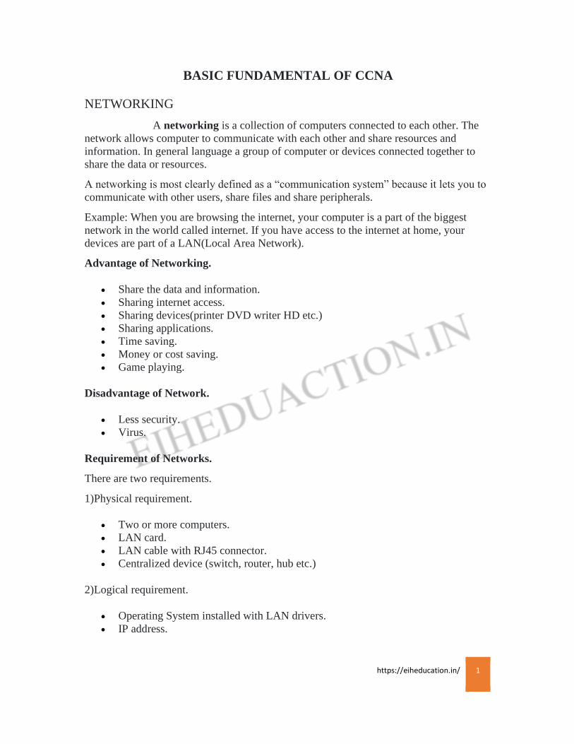
Classification of Network.
Local Area Network- LAN:
A Local Area Network is a computer network covering a small physical area like a home,
office, or small group of building.
Its refers to a combination of computer hardware and transmission media that is relatively small
in addition.
Some of the LAN technologies are Ethernet, Token Ring and FDDI. Ethernet is by far the most
popular wired LAN technology.
Transmit for short range typically 100m.
LAN Characteristics
• Limited geographic area
• Moderate to high data rate
• Inexpensive media
• High connectivity and access
• Decentralized control
Personal Area Network-PAN:
Short range networking technology that uses the body for transmitting signal including
devices that user wears or comes in close contacts, like example: Mobile Bluetooth etc.
Transmit for short range typically 10m.
Campus Area Network-CAN:
A Campus Area Network is a computer network made up of an interconnections of LAN a
limited geographical area. It can be consider one form of a metropolitan Area Network(MAN)
specific to an academic city.
Sample Area Network-SAN:
https://eiheducation.in/ 3
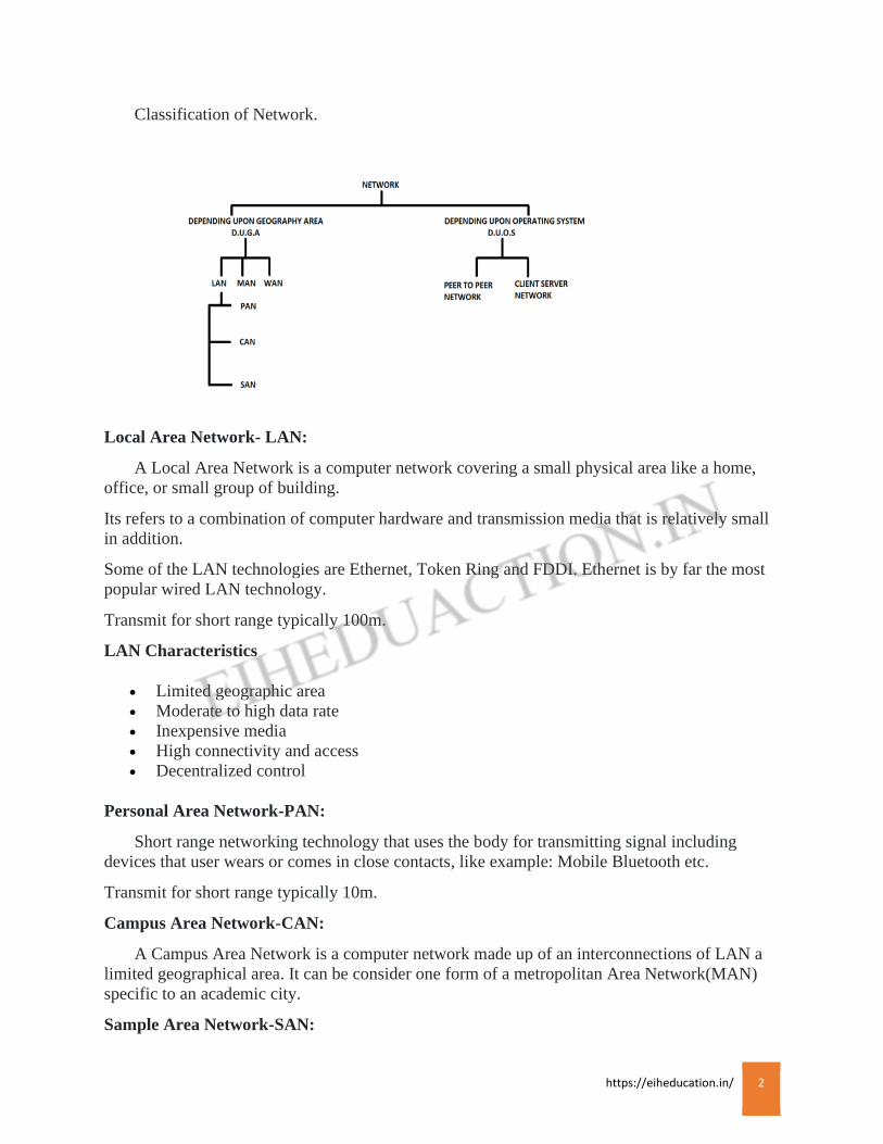
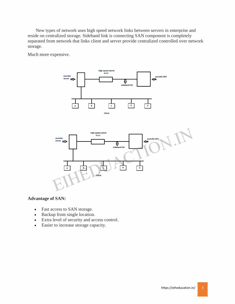
New types of network uses high speed network links between servers in enterprise and
reside on centralized storage. Sideband link is connecting SAN component is completely
separated from network that links client and server provide centralized controlled over network
storage.
Much more expensive.
Advantage of SAN:
• Fast access to SAN storage.
• Backup from single location.
• Extra level of security and access control.
• Easier to increase storage capacity.
https://eiheducation.in/ 4
Metropolitan Area Network-MAN:
Two or more computer are connected to each other that are geographical area separated and
connected within city to city.
Telephone media is used.
Example: College Campus.
Wide Area Network-WAN:
Two or more computer are connected to each other that are geographical area separated and
connected with city to city or country to country.
Satellite media is used.
Example: Airport network, Internet.
WAN Characteristics
• Lower bandwidth compared to LANs
• Typically interconnected multiple LANs
• Exist in an unlimited geographic area
• Some resources, typically data communication equipment, is managed externally to
organizations using the wan
Peer to peer network:
Peer to peer network allows any entity to both request and provide network services. Peer to
peer network software is designed so that peer perform the same or similar functions for each
other.
Server client network or server centric network:
server client network involve strictly defined roles. By definition, a server client network
places restriction upon which entity may take request or service them. Currently, the most
popular personal computer networks are server client network.
https://eiheducation.in/ 5
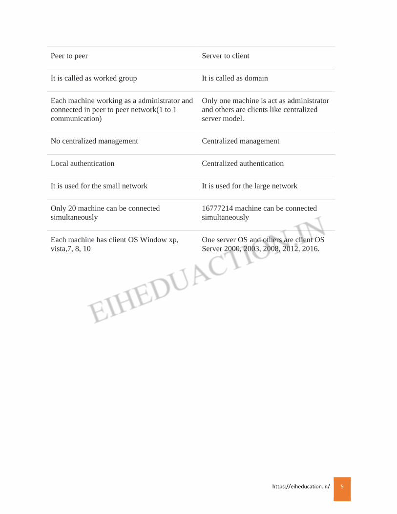
Peer to peer Server to client
It is called as worked group It is called as domain
Each machine working as a administrator and
connected in peer to peer network(1 to 1
communication)
Only one machine is act as administrator
and others are clients like centralized
server model.
No centralized management Centralized management
Local authentication Centralized authentication
It is used for the small network It is used for the large network
Only 20 machine can be connected
simultaneously
16777214 machine can be connected
simultaneously
Each machine has client OS Window xp,
vista,7, 8, 10
One server OS and others are client OS
Server 2000, 2003, 2008, 2012, 2016.
https://eiheducation.in/ 6
Topology
A topology refers to the manner in which the cable is run to individual workstation(host
computer, group of computer) or the network. It describe the actual layout of the computer network
hardware. Two or more devices connect to a link, two or more links form a topology.
There are two types of topologies.
1)physical topology 2)Logical topology
Physical topology: The physical topology of a network refers to the configuration of cables,
computers and other peripherals.
Logical topology: The logical topology is the method used to pass information between
workstations.
Types of Topology:
Star Topology
Bus Topology
Ring Topology
Mesh Topology
Hybrid Topology
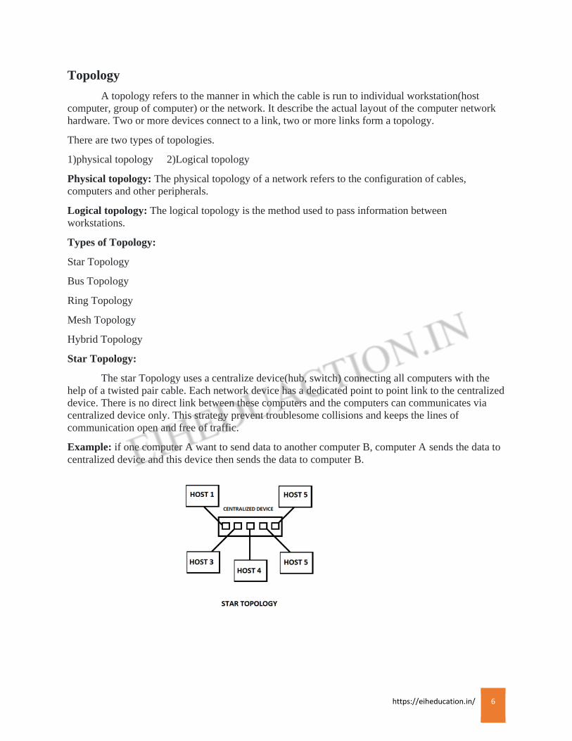
Star Topology:
The star Topology uses a centralize device(hub, switch) connecting all computers with the
help of a twisted pair cable. Each network device has a dedicated point to point link to the centralized
device. There is no direct link between these computers and the computers can communicates via
centralized device only. This strategy prevent troublesome collisions and keeps the lines of
communication open and free of traffic.
Example: if one computer A want to send data to another computer B, computer A sends the data to
centralized device and this device then sends the data to computer B.
https://eiheducation.in/ 7
Advantage:
Presently star topology is used.
Network management is much easier.
Ease of cabling installation.
Easy to detect faults and remove parts.
Network reliability is high.
If one computer or link fails, the entire system does not collapse. Only that link or computer is
affected.
Disadvantage:
If a centralized device is fails, entire system collapses.
Cabling cost is more as each node is connected individually to the centralized device.
Require more cable than most topologies.
Moderately difficult to install.
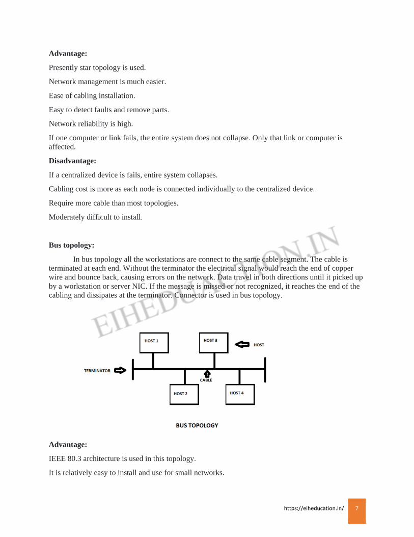
Bus topology:
In bus topology all the workstations are connect to the same cable segment. The cable is
terminated at each end. Without the terminator the electrical signal would reach the end of copper
wire and bounce back, causing errors on the network. Data travel in both directions until it picked up
by a workstation or server NIC. If the message is missed or not recognized, it reaches the end of the
cabling and dissipates at the terminator. Connector is used in bus topology.
Advantage:
IEEE 80.3 architecture is used in this topology.
It is relatively easy to install and use for small networks.

https://eiheducation.in/ 8
It requires less media then other topologies.
Failure of one node does not affect the network functioning.
Low cost.
Expansion is easier. New node can be easily added by using a connector.
Disadvantage:
Entire network fails if there is a break in main cable.
Difficult to configure
Difficult to troubleshoot because everything happens on a single media segment.
Higher network traffic slowdown the bus speed. Only one device transmits at a time, other devices
wait for their turn.
Problems of collisions.
Ring Topology:
The ring topology is a circular loop of point to point links. Each device connects directly to
the ring or indirectly through an interface device or drop cable. Unlike bus topology it does not have
terminators at the end of the cables. In this topology data moves from one node to another. Data
moves in one direction only. Each workstation checks the message for a matching destination
address. If the address doesn’t match the node simply regenerates the message and sends it on its
way. If the address matches, the node accept the message and sends a reply to the sender.
https://eiheducation.in/ 9
Advantage:
Ease of installation.
Low cost as only one cable is used.
A special internal feature called beaconing allows trouble workstations to identify themselves
quickly.
There are no collisions.
Data packets travel at greater speed.
Disadvantage:
A ring network requires more physical media than a bus network.
Media failure on unidirectional or single loop causes complete network failure.
A break in a cable ring brings down the entire network.
Difficult to reconfigure ring topology.
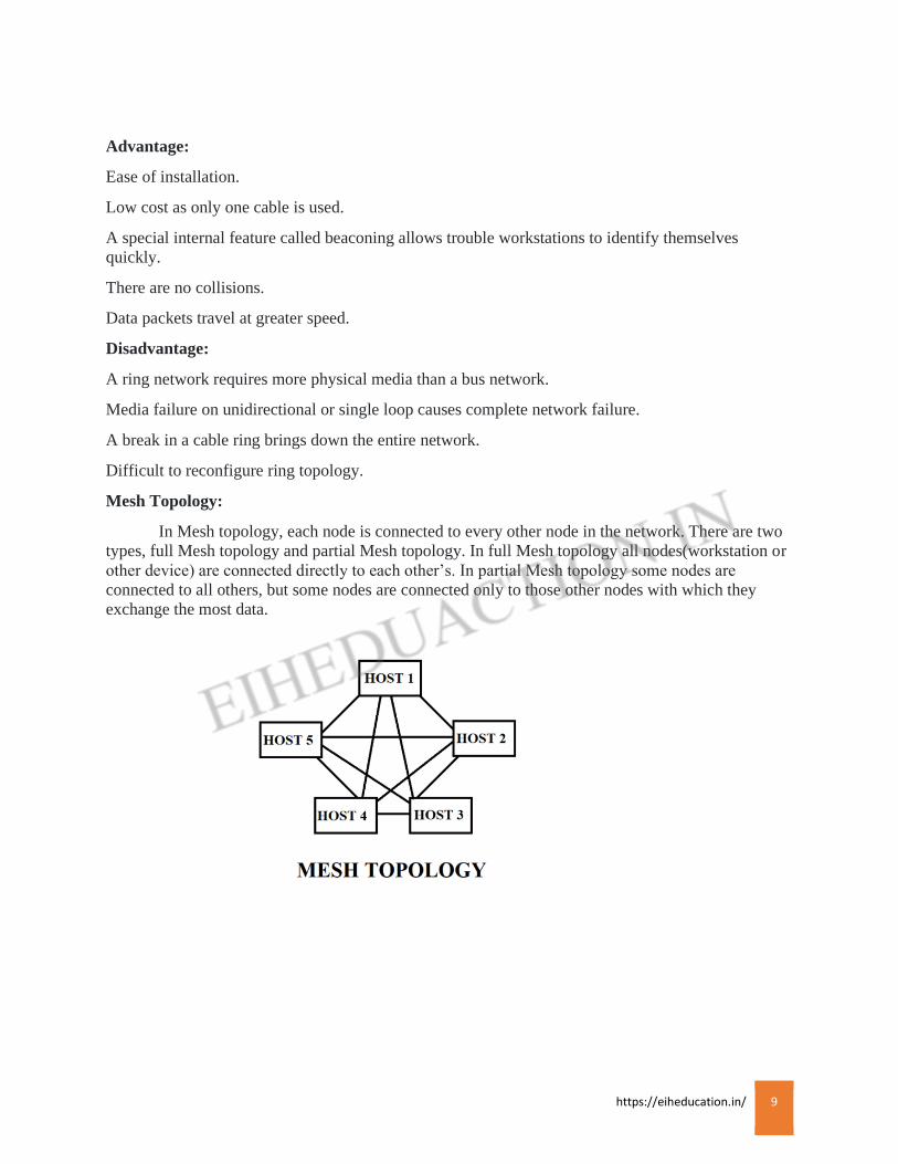
Mesh Topology:
In Mesh topology, each node is connected to every other node in the network. There are two
types, full Mesh topology and partial Mesh topology. In full Mesh topology all nodes(workstation or
other device) are connected directly to each other’s. In partial Mesh topology some nodes are
connected to all others, but some nodes are connected only to those other nodes with which they
exchange the most data.
https://eiheducation.in/ 10
Advantage:
If one link fails, the entire system continuous to work.
There is no traffic congestion problem as dedicated links are being used.
Dedicated links ensures faster transmission without any delay.
Dedicated links also ensure data privacy and security.
Disadvantage:
Connecting each device to every other device in the network make installation and reconfiguration
difficult.
Cabling cost is high.
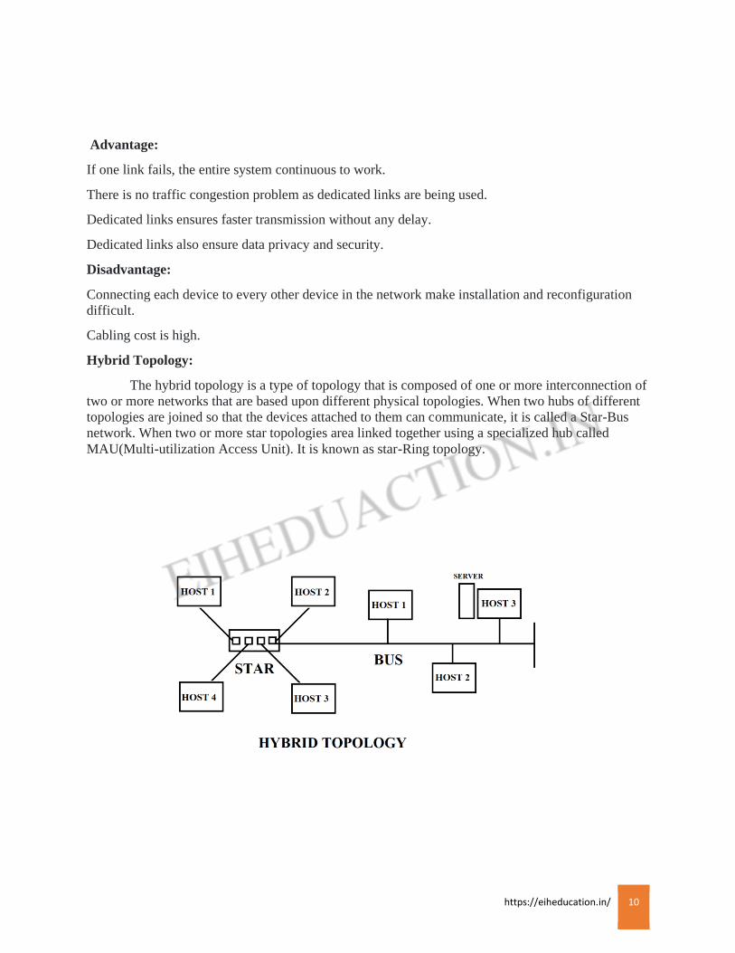
Hybrid Topology:
The hybrid topology is a type of topology that is composed of one or more interconnection of
two or more networks that are based upon different physical topologies. When two hubs of different
topologies are joined so that the devices attached to them can communicate, it is called a Star-Bus
network. When two or more star topologies area linked together using a specialized hub called
MAU(Multi-utilization Access Unit). It is known as star-Ring topology.

https://eiheducation.in/ 11
Transmission Media
Transmission Media
Data is represented by computers and other telecommunication devices using signals. Signals are
transmitted in the form of electromagnetic energy from one device to another. Electromagnetic signals
travel vacuum, air or other transmission mediums to travel between one point to another (from source to
receiver).
The first layer of OSI model that is physical layer is related to transmission media.
Types of transmissions
A transmission can be simplex, half-duplex or full-duplex.
In simplex transmission, signals are transmitted in only one direction; one device act as a
transmitter and the other acts receiver, example person talking at a radio station act as transmitter
and the person with a radio who is listening act as a receiver.
In the half-duplex transmission, both stations can transmit and receive but only one at a
time, example walky-talky, one can only talk at a time when other is on listening mode then
when one goes to listening mode the other is able to talk.
In full-duplex transmission, both devices can transmit and receive simultaneously, example
telephone both the users can talk as well as listen at the same time. Hence in full duplex
transmission, the medium is carrying signals in both directions at the same time.
There are two types of transmission media:
1.Guide or Wired. 2.Unguided or wireless.
https://eiheducation.in/ 12
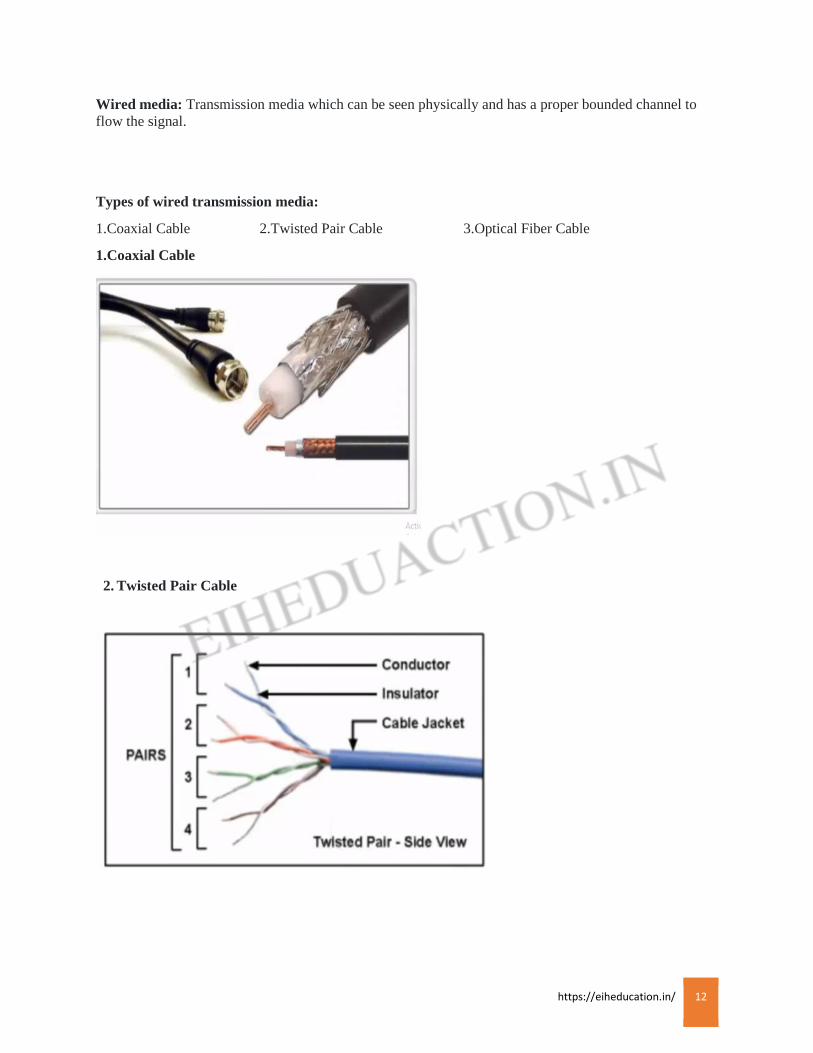
Wired media: Transmission media which can be seen physically and has a proper bounded channel to
flow the signal.
Types of wired transmission media:
1.Coaxial Cable 2.Twisted Pair Cable 3.Optical Fiber Cable
1.Coaxial Cable
2. Twisted Pair Cable

https://eiheducation.in/ 13
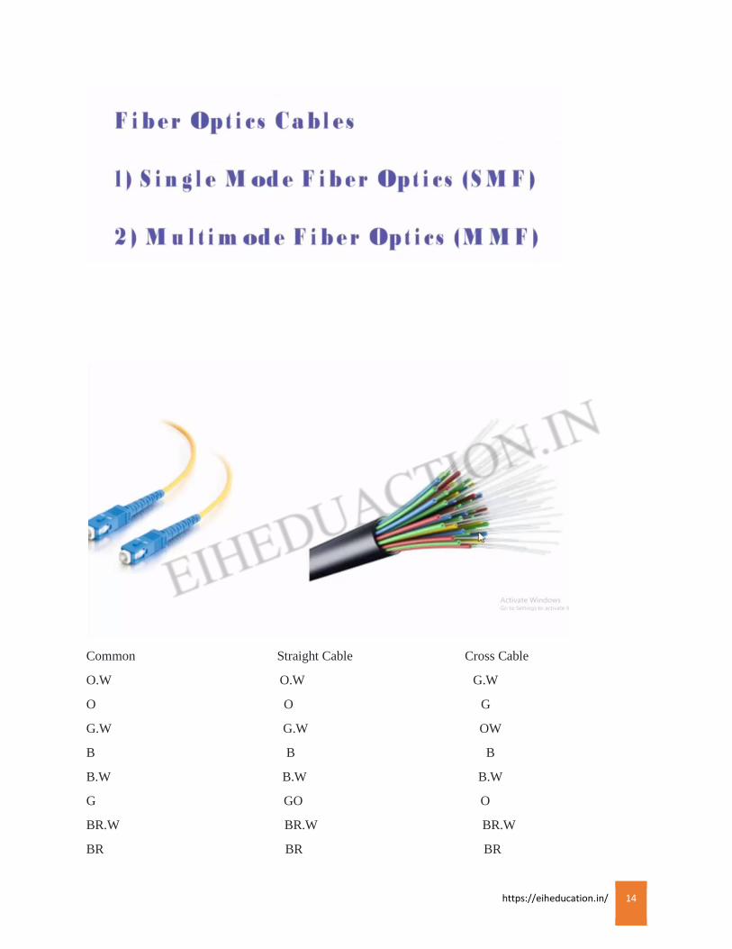
3. Optical Fiber Cable
https://eiheducation.in/ 14
Common Straight Cable Cross Cable
O.W O.W G.W
O O G
G.W G.W OW
B B B
B.W B.W B.W
G GO O
BR.W BR.W BR.W
BR BR BR
https://eiheducation.in/ 15
Wireless Media:
Wireless transmission media is the one in which data signals gets transmitted through the air. They
are not guided or bound to a channel to follow.
Types of wireless Transmission media:
1.Radio Transmission 2.Microwave Transmission
TP UTP
https://eiheducation.in/ 16
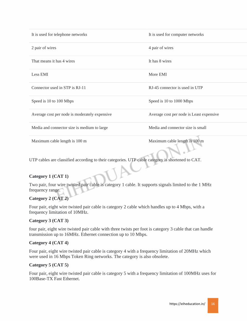
It is used for telephone networks It is used for computer networks
2 pair of wires 4 pair of wires
That means it has 4 wires It has 8 wires
Less EMI More EMI
Connector used in STP is RJ-11 RJ-45 connector is used in UTP
Speed is 10 to 100 Mbps Speed is 10 to 1000 Mbps
Average cost per node is moderately expensive Average cost per node is Least expensive
Media and connector size is medium to large Media and connector size is small
Maximum cable length is 100 m Maximum cable length is 100 m
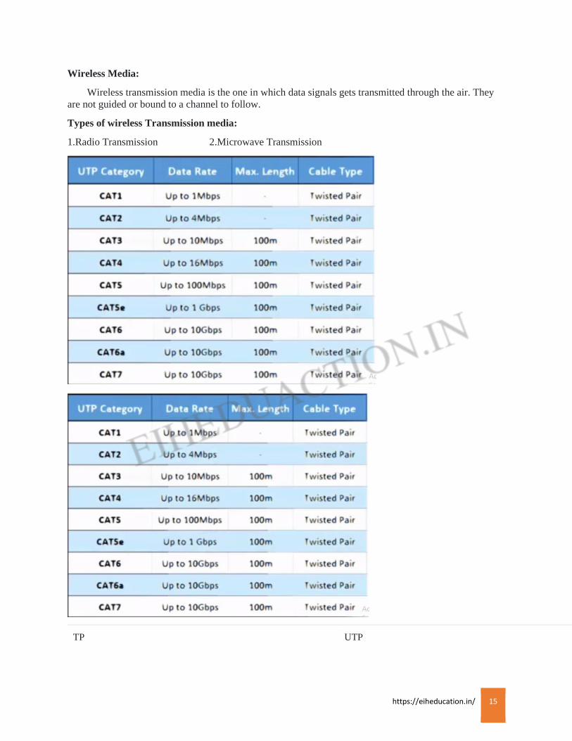
UTP cables are classified according to their categories. UTP cable category is shortened to CAT.
Category 1 (CAT 1)
Two pair, four wire twisted pair cable is category 1 cable. It supports signals limited to the 1 MHz
frequency range.
Category 2 (CAT 2)
Four pair, eight wire twisted pair cable is category 2 cable which handles up to 4 Mbps, with a
frequency limitation of 10MHz.
Category 3 (CAT 3)
four pair, eight wire twisted pair cable with three twists per foot is category 3 cable that can handle
transmission up to 16MHz. Ethernet connection up to 10 Mbps.
Category 4 (CAT 4)
Four pair, eight wire twisted pair cable is category 4 with a frequency limitation of 20MHz which
were used in 16 Mbps Token Ring networks. The category is also obsolete.
Category 5 (CAT 5)
Four pair, eight wire twisted pair cable is category 5 with a frequency limitation of 100MHz uses for
100Base-TX Fast Ethernet.

https://eiheducation.in/ 17
Category 5e (enhanced)
Four pair, eight wire twisted pair cable is category 5e with a frequency limitation of 100MHz. it can
be used for 100Base-T(Gigabit Ethernet).
Category 6 (CAT 6)
Four pair, eight wire twisted pair cable is category 6 with a frequency limitation of 250MHz. It is
also used for 100Base-T(Gigabit Ethernet).
Wiring Standard:
Wiring standards are used to set Ethernet cables according to the connection of it between similar or
dissimilar devices.
There are three types of Ethernet cables available
1.Straight-through cable
2.Crossover cable
3.Rolled cable
T-568A and T568B are the two wiring standards for RJ-45 connector data cable specified by
TIA/EIA-568-A wiring standard document. The two wiring standard are used to create a cross-over
cable where T-568-A used on one end and t-568B on the other end. In straight-through cable where
on both ends you can use T568A or T-568B wiring standard.
Straight-through cable: It is used to connect dissimilar devices like computer to switch, computer to
hub.
Crossover cable: It is used to connect similar devices like computer to computer, hub to hub, switch
to switch.
Rollover cable: A rollover cable is a network cable that connects a computer terminal to a network
router’s console port.
https://eiheducation.in/ 18
Devices
Devices
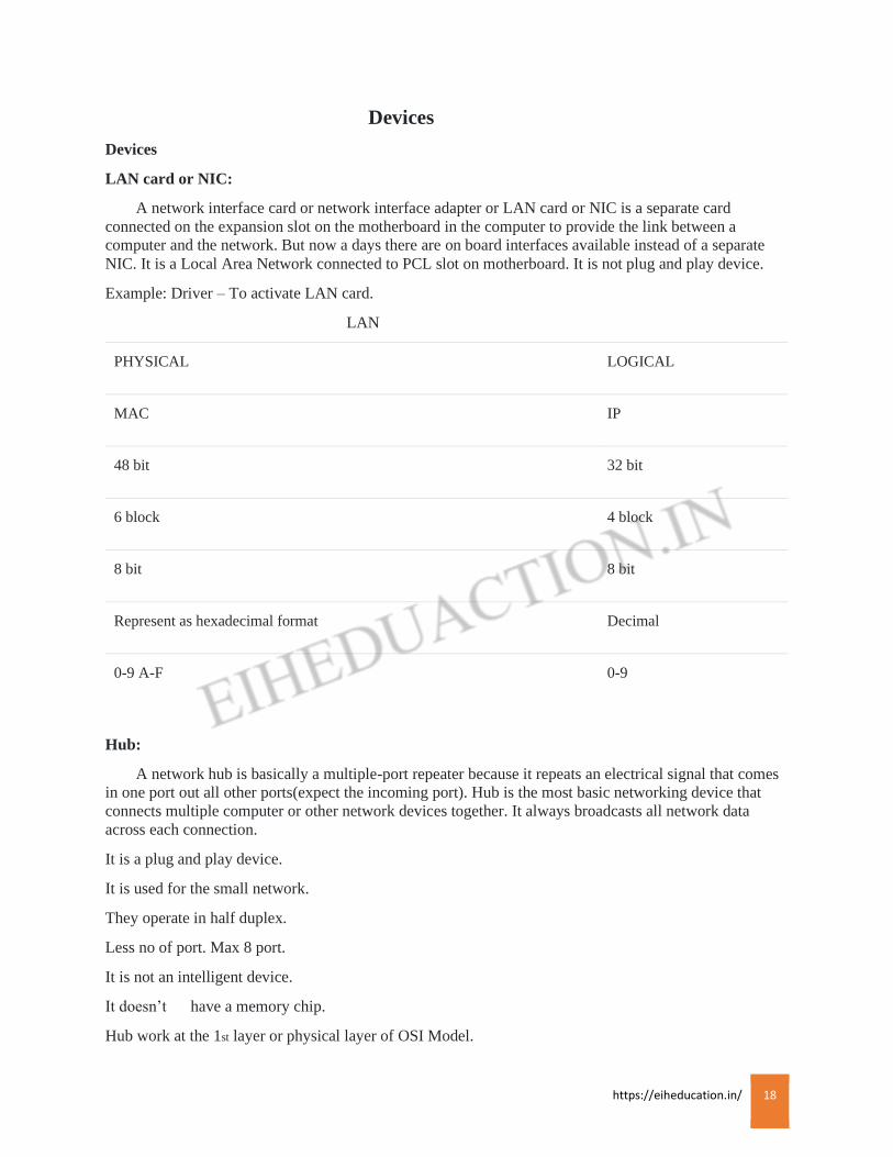
LAN card or NIC:
A network interface card or network interface adapter or LAN card or NIC is a separate card
connected on the expansion slot on the motherboard in the computer to provide the link between a
computer and the network. But now a days there are on board interfaces available instead of a separate
NIC. It is a Local Area Network connected to PCL slot on motherboard. It is not plug and play device.
Example: Driver – To activate LAN card.
LAN
PHYSICAL LOGICAL
MAC IP
48 bit 32 bit
6 block 4 block
8 bit 8 bit
Represent as hexadecimal format Decimal
0-9 A-F 0-9
Hub:
A network hub is basically a multiple-port repeater because it repeats an electrical signal that comes
in one port out all other ports(expect the incoming port). Hub is the most basic networking device that
connects multiple computer or other network devices together. It always broadcasts all network data
across each connection.
It is a plug and play device.
It is used for the small network.
They operate in half duplex.
Less no of port. Max 8 port.
It is not an intelligent device.
It doesn’t have a memory chip.
Hub work at the 1st layer or physical layer of OSI Model.
https://eiheducation.in/ 19
Internal architecture: Its form a Bus topology, so only one collision occur in hub. To occur collision Run
CSMA/CD(Carrier Sense Multiple Access Collision Detection). It work on physical layer and send the
data in binary format or bits.
Switch:
A LAN switch is a centralized device connected to multiple PC or nodes. each port on a switch is in
a separate collision domain. It is quiet intelligent to understand the mac-address of the PC or nodes and
stores into a repository called CAM table or mac-address-table. Every switch port is made up of special
hardware called ASIC(Application Specific Integrated Circuit.
It is a plug and play device.
It is use for large network.
They operate in full duplex.
We can connect n-number of host.
It is a intelligent device.
It has a memory chip (ASIC).
Its broadcast only once(1st time) the unicast the message after learn mac-address.
It can learn mac-address.
Internal structure: Its work on a data link layer and data send in frame format.
One domain has multiple collision.
Bridge:
A network bridge is a device that divides a network into segment. Each segment represent a separate
collision domain, so number of collision on the network is reduced. It is communication between different
different of the segment. It is work as like a switch. But the main different between switch and bridge is
that switch is hardware based whereas bridge is software based.
Repeater:
It is regenerate the signal and it work on a physical layer.
Router:
A router is a network device that connects different network s by routing packet from one network to
another. In other language, it is communication between two different networks. A router is a device that
forward data packets between computer networks. A router is considered a Layer 3 device of the OSI
Model that is Network Layer. Each port on a router is in a separate collision and broadcast domain and
can run in the full duplex mode.
Functions of Router:
It is communication between internal or external network.
Data format is packet.
Packet switching and packet forwarding: Router can switch the packet according to interface to forward
the data(packet)
Packet filtering: filtering is a process when router can flush unwanted packet.

https://eiheducation.in/ 20
Path selection: router always select best path to reach the destination.
Gateway:
it is not a device it is logical terms means router Ethernet address, it is called as a default gateway.
https://eiheducation.in/ 21
OSI MODEL
OSI Model
The Open Systems Interconnection (OSI) Model is a conceptual model that characterizes and
standardizes the internal functions of a communication system by partitioning it into abstraction layers.
The OSI model was created by the International Organization for Standardization (ISO). It is layered
model that was created to enable different networks to communicate between disparate systems. A layer
serves the layer above it and is served by the layer below it.
Example: a layer that provides error-free communications across a network provides the path needed by
applications above it. While it calls the next lower layer to send and receive packets that make up the
contents of that path.
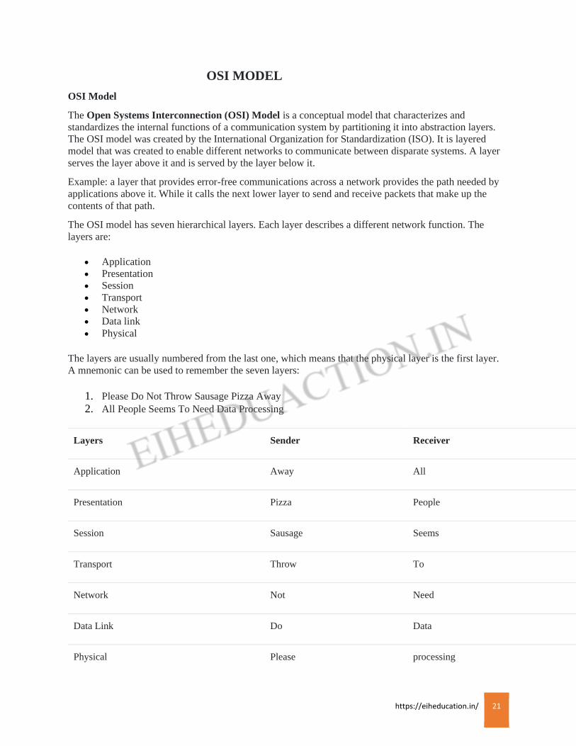
The OSI model has seven hierarchical layers. Each layer describes a different network function. The
layers are:
• Application
• Presentation
• Session
• Transport
• Network
• Data link
• Physical
The layers are usually numbered from the last one, which means that the physical layer is the first layer.
A mnemonic can be used to remember the seven layers:
1. Please Do Not Throw Sausage Pizza Away
2. All People Seems To Need Data Processing
Layers Sender Receiver
Application Away All
Presentation Pizza People
Session Sausage Seems
Transport Throw To
Network Not Need
Data Link Do Data
Physical Please processing
https://eiheducation.in/ 22
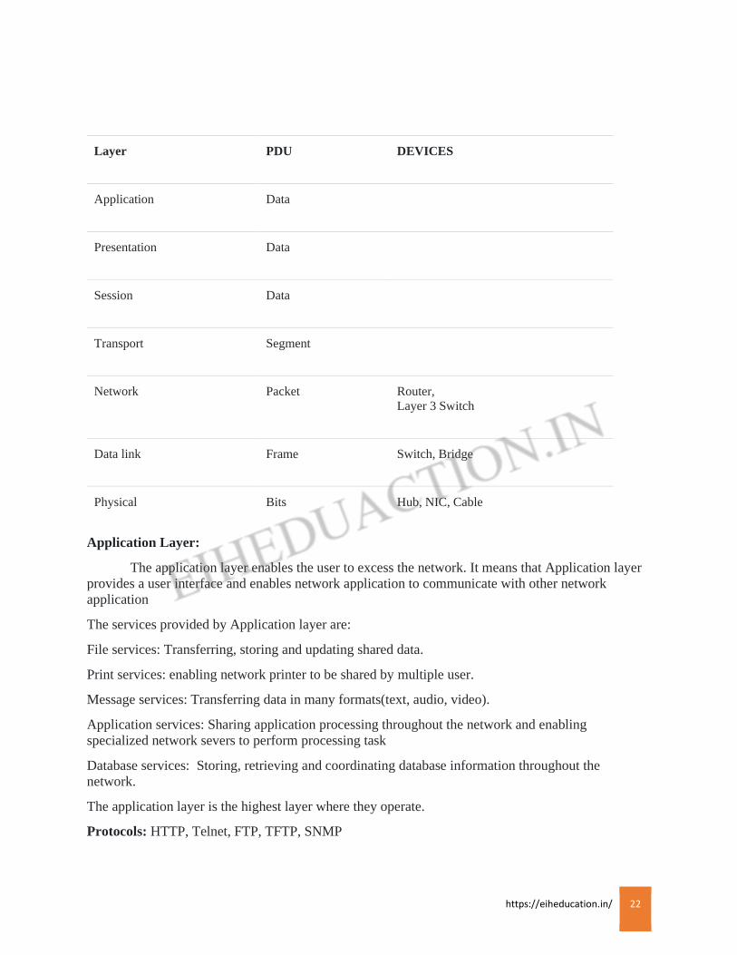
Layer PDU DEVICES
Application Data
Presentation Data
Session Data
Transport Segment
Network Packet Router,
Layer 3 Switch
Data link Frame Switch, Bridge
Physical Bits Hub, NIC, Cable
Application Layer:
The application layer enables the user to excess the network. It means that Application layer
provides a user interface and enables network application to communicate with other network
application
The services provided by Application layer are:
File services: Transferring, storing and updating shared data.
Print services: enabling network printer to be shared by multiple user.
Message services: Transferring data in many formats(text, audio, video).
Application services: Sharing application processing throughout the network and enabling
specialized network severs to perform processing task
Database services: Storing, retrieving and coordinating database information throughout the
network.
The application layer is the highest layer where they operate.
Protocols: HTTP, Telnet, FTP, TFTP, SNMP
https://eiheducation.in/ 23
HTTP(Hypertext Transfer Protocol): The HTTP is an application protocol for distributed,
collaborative, hyper media information systems. HTTP is the foundation of data communication for
the World Wide Web. HTTP protocol uses port number 80.
It is used to make a request from the client to the web servers that open the right resource when you
click on a link or type a URL in the web browser,.
Telnet: Telnet protocol uses port number 23. Through telnet user can access a remote client machine
resources without being physical present over there. In telnet access you gain a virtual terminal
machine that act as an interface with the chosen remote client machine.
FTP(File Transfer Protocol): The FTP is a standard network protocol used to transfer computer
files from one host to another host over a TCP-based network such as the internet. It uses port
number 21.
TFTP(Trivial File Transfer Protocol): The TFTP is a simple version of FTP that allows a client to
get from or put a file onto a remote host. TFTP uses port number 69. TFTP lacks security and most
of the advance features offered by more robust file transfer protocols such as File Transfer Protocol.
It cannot be user for directory browsing; it can do nothing but only send and receive
files.SNMP(Simple Network Management Protocol): It used to collect and manipulate information
about network components. Devices that typically support SNMP include routers, switches, servers,
workstation, printers, modem racks and more.
Presentation Layer: The presentation layer is considered with the syntax and symmetric of the
information. It defined data formats.
The presentation layer formats data for the Application layer. Therefor it also set standards for
multimedia and other formats.
• Example: JPEG, BMP TIFF, PICT
• MPEG,WMV,AVI
• ASCII, EBCDIC
• MIDI,WAV.
The responsibility of presentation layer are:
• Formatting and translation of data between systems.
• Negotiation of data transfer syntax between systems.
• Processes such as encryption, compression are handled by this layer.
Note: Everyone knows about this protocols Right.!!
Session Layer: The session layer establishes, maintain and synchronizes the interaction between
communication system. In other words, this layer determines how to establish, control and terminate
a session between the two systems.
The responsibilities of session layer are:
Management of multiple session.
Assignment of session ID number to each session, which is then used by the Transport layer to
properly route the messages.
https://eiheducation.in/ 24
Dialog control: specifying how the network devices coordinate with each other(simplex, half duplex,
full duplex).
Termination of communication sessions between network hosts upon completion of the data transfer.
The session layer protocols and interfaces coordinate requests and responses between different host
using the same application, there protocols and interfaces include.
• Network File System (NFS).
• Apple Session Protocol (ASP).
• Structured Query Language (SQL).
• Remote Procedure Call (RPC)
• X Window.
SQL: While SQL Server works with a large variety of protocols, TCP/IP Sockets, Named Pipes, and
Multi-Protocol are the most common. … Once connected to the database, access to SQL objects
(such as tables, views, and stored procedures) is controlled using standard SQL Server access
permissions.
NFS(Network File System): It is a distributed file system protocol allowing a user on a client
computer to access files over a network much like a local storage access. It allows two different types
of file system to interoperate. It has different version: NFS2, NFS3, and NFS4. NFS protocol uses
port no 2049.
ASP: ASP is a bare-bones transport-layer protocol which uses IP to transmit messages to
an ASP “port” at the destination host. ASP is somewhat similar to UDP in the real world. …
As ASP is such a simple protocol, it turns out that the session needs to hold no data except for a
template message header.
RPC(Remote Procedure Call): is a protocol that one program can use to request a service from a
program located in another computer on a network without having to understand the network’s
details. A procedure call is also sometimes known as a function call or a subroutine call
X Window: The X Window System core protocol is the base protocol of the X Window System,
which is a networked windowing system for bitmap displays used to build graphical user interfaces
on Unix, Unix-like, and other operating systems.
Transport Layer: The Transport Layer is responsible for process to process delivery of the entire
message. This layer ensure that the whole message arrive error free control, and in order providing
both flow and error control at source to destination level.
The transport layer provides a transition between the upper and lower layers of the OSI model,
making the upper and lower layers transparent from each other. Upper layers format and process data
without any concern for delivery and lower layers prepare the data for delivery by fragmenting and
attaching transport required information.
The responsibilities of transport layer are:
Service point addressing: The transport layer header includes a type of address called services point
address(code address) so as to ensure the delivery of message from specific process from one system
to specific process on another system.
https://eiheducation.in/ 25
Segmentation and reassembly: A message is divided into segment and each segment is given a
sequences number, using the sequence number the transport layer reassemble the message when they
arrive at the destination.
Connection control: The transport layer can be either connection less or connection oriented in
connection less transport layer, each segment is considered as an independent packet. In connection
oriented transport layer, a connection is establish before delivery of the packet.
Flow control: The transport layer is responsible for flow control, this error control is performed
process to process level.
Protocols: TCP and UDP
TCP(Transmission Control Protocol): The TCP is a core protocol of the internet protocol suite. It
originated in the initial network implementation in which it complemented the internet protocol
IP. TCP is the protocol that major Internet application such as the World Wide Web, email, remote
administration and file transfer rely on. TCP provide reliable, ordered and error-checked delivery of a
stream of octets between application running on host communicating over an IP network.
UDP(User Datagram Protocol): The UDP is one of the core members of the Internet Protocol suite.
UDP uses a simple connectionless transmission model with a minimum of protocol mechanism. It
has no handshaking mechanism. There is no guarantee of delivery, ordering or duplicate protection.
UDP provides checksum for data integrity and port number for addressing different function at the
source and destination of the datagram.
Network Layer: The network layer describes how data is routed across networks and on the
destination. Each packet has a header and header contains source IP address and Destination IP
address. The two main function of network layer is Forwarding and Routing.
• The other functions include: Maintaining address of neighboring routers.
• Maintaining a list of known networks.
Determining the next network point to which data should be sent. Packet forwarded from the
Transport to the network layer become datagrams and network-specific(routing) information
is added. The network layer protocol then ensure that the data arrives at the intended
destination.
Device like Router reside over the Network Layer.
Protocols: IP, IPX, Apple Talk, DECNET
IP(Internet Protocol): The IP is the principal communication protocol in the internet protocol suite
for relaying datagram across network boundaries. Its routing function enables internetworking and
essentially establishes the internet. It has the task of delivering packets from the source host to the
destination host based on the IP address in the packet headers. For this purpose, IP define packet
structure that encapsulate the data to be delivered. It also defined addressing methods that are used to
label the datagram with source and destination information.
IPX: IPX stands for Internetwork Packet Exchange. IPX is networking protocols used primarily on
networks using the Novell NetWare operating systems.
https://eiheducation.in/ 26
AppleTalk: AppleTalk was a proprietary suite of networking protocols developed by Apple Inc. for
their Macintosh computers. AppleTalk includes a number of features that allow local area networks
to be connected with no prior setup or the need for a centralized router or server of any sort.
DECNET: DECnet is a suite of network protocols created by Digital Equipment Corporation.
Initially built with three layers, it later (1982) evolved into a seven-layer OSI-compliant
networking protocol. DECnet was built right into the DEC flagship operating system VMS since its
inception.
Data-Link Layer: The Data-link layer transform the physical layer to a reliable link. It makes the
physical layer to appear as error free for the upper layer. It combines packets into bytes and bytes
into frames. Each frame has a header and a trailer. A header contains the source and destination
MAC address. A trailer contains the frame check sequence field, used for errors detection. The data
link layer is divided into two sub layers:
Logical Link Control: uses for flow control and error detection.
Media Access Control: used for hardware addressing and controlling access method.
Devices like switches reside over the data link layer.
LAN Protocol:
LLC(Logical Link Control): The LLC sub layer acts as an interface between the Media Access
control (MAC) sub layer and the network. The LLC sub layer provides multiplexing mechanism. It
can also provide Flow control and Automatic Repeat Request (ARQ) error management mechanism.
Ethernet: Ethernet is the most widely installed Local Area Network technology. It describe how
network device can format data for transmission to the network devices on the same network
segment, and how to put the data on the network connection.
Token Ring: It is a communication protocol for Local Area Network. It uses a special three-byte
frame called a “Token” that travel along a logical “Ring” of workstations or server.
Wireless: IEEE 802.11 is a set of media access control (MAC) and physical layer (PHY)
specifications for implementing wireless local area network (WLAN) computer communication in
the 900 MHz and 2.4, 3.6, 5, and 60 GHz frequency bands.
Wan Protocol:
HDLC(High-level Data Link Control): This protocol is defined by the ISO and it is therefore an
open standard. HDLC uses synchronous serial transmission for error free communication between
two devices.
PPP(Point-to-Point Protocol): PPP is a WAN protocol that work on a Layer 2 by encapsulating
frame for transmission over a variety of physical link such as serial cables, cell phones, fiber optic
cable among others.
Frame Relay: is an industry standard switched data link protocol. It uses virtual circuits and it
evolved from the X.25 protocol. It is more efficient and does not include options such as flow control
and error control.
ISDN(Integrated Service Digital Network): it is a set of communication standard for
simultaneously digital transmission of voice, video, data. It is a circuit switched telephone network
system.
https://eiheducation.in/ 27
ATM(Asynchronous Transfer Mode): is a switching technology used by telecommunication
network that uses asynchronous time-division multiplexing to encode data into small, fixed-
sized cells. This is different from Ethernet or internet, which use variable packet sizes for data or
frames.
Physical Layer: The physical layer of the OSI model sets standards for sending and receiving
electrical signals between devices. It acts as an interface between network layer and physical devices
like hubs and switches. It deals with the physical characteristics of the transmission medium, cables,
connectors, NIC (Network Interface Card) or LAN card.
The physical layers provide the following services:
• Modulate the process of converting a signal from one form to another so that it can be
physically transmitted over a communication channel.
• Bit-by-Bit delivery.
• Collision detection.
• Signal equalization to ensure reliable connections and facilitate multiplexing.
• Forward error correction coding such as error correction code.
• Transmission mode control.
Cables, connectors and Hubs reside over the Physical Layer.
PROTOCOLS
Category 5 or Cat 5: It is a type of UTP Cable, it has Four pair, eight wire twisted pair cable is
category 5 with a frequency limitation of 100MHz used fir 100Base-TX Fast Ethernet, synchronous
Optical network, and optical Carrier, Asynchronous Transfer Mode. It is best to go for Cat 5e instead
of CAT 5 as you can get both the cable at same price.
RJ45: The connector used for UTP cable is RJ-45 for computer networking which has four pair and
8 wires. RJ45 connector is most of the time connected to the UTP cable. The job of connecting RJ45
connector to UTP cable is called crimping.
There is one more connector “RJ-11” which is used for telephone line that has two pair and 4 wires.
RJ11 is relatively small in size of RJ45 connector.
V.35: This is the ITU standard for high speed serial communications. This cable is used to connect
the DTE device to modems and similar digital line devices.
EIA/TIA 232: It is a protocol that specifies speeds of up to 64Kbps using a 25 pin connector for
short distance. The EIA/TIA-232C standard, formerly1 known as RS-232, is a standard defining
details found at layer 1 of the OSI Reference Model. EIA/TIA-232 networks are point-to-point,
intended to connect only two devices
https://eiheducation.in/ 28
TCP/IP
TCP/IP
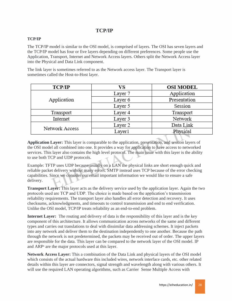
The TCP/IP model is similar to the OSI model, is comprised of layers. The OSI has seven layers and
the TCP/IP model has four or five layers depending on different preferences. Some people use the
Application, Transport, Internet and Network Access layers. Others split the Network Access layer
into the Physical and Data Link component.
The link layer is sometimes referred to as the Network access layer. The Transport layer is
sometimes called the Host-to-Host layer.
Application Layer: This layer is comparable to the application, presentation, and session layers of
the OSI model all combined into one. It provides a way for application to have access to networked
services. This layer also contains the high level protocol. The main issue with this layer is the ability
to use both TCP and UDP protocols.
Example: TFTP uses UDP because usually on a LAN the physical links are short enough quick and
reliable packet delivery without many errors. SMTP instead uses TCP because of the error checking
capabilities. Since we consider our email important information we would like to ensure a safe
delivery.
Transport Layer: This layer acts as the delivery service used by the application layer. Again the two
protocols used are TCP and UDP. The choice is made based on the application’s transmission
reliability requirements. The transport layer also handles all error detection and recovery. It uses
checksums, acknowledgments, and timeouts to control transmission and end to end verification.
Unlike the OSI model, TCP/IP treats reliability as an end-to-end problem.
Internet Layer: The routing and delivery of data is the responsibility of this layer and is the key
component of this architecture. It allows communication across networks of the same and different
types and carries out translations to deal with dissimilar data addressing schemes. It inject packets
into any network and deliver them to the destination independently to one another. Because the path
through the network is not predetermined, the packets may be received out of order. The upper layers
are responsible for the data. This layer can be compared to the network layer of the OSI model. IP
and ARP6 are the major protocols used at this layer.
Network Access Layer: This a combination of the Data Link and physical layers of the OSI model
which consists of the actual hardware this included wires, network interface cards, etc. other related
details within this layer are connectors, signal strength and wavelength along with various others. It
will use the required LAN operating algorithms, such as Carrier Sense Multiple Access with
https://eiheducation.in/ 29
Collision Detect (CMSA/CD) or IBM Token Passing etc. and is responsible for placing the data
within frame. The frame format is dependent on the system being used. Example: Ethernet LAN,
Frame relay etc. the frame is the package that holds the data, in the same way as an envelope holds a
letter. The frame hold the hardware address of the host and checking algorithm for data integrity.
This layer has actually not been specified in details because it depends on which technology is being
used such as Ethernet. So freedom is given to this layer as far as implementation is concerned.
Binary Conversion
Binary Conversion
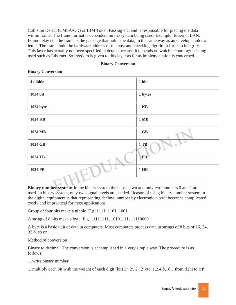
4 nibble 1 bits
1024 bit 1 bytes
1024 byte 1 KB
1024 KB 1 MB
1024 MB 1 GB
1024 GB 1 TB
1024 TB 1 PB
1024 PB 1 HB
Binary number system: In the binary system the base is two and only two numbers 0 and 1 are
used. In binary system, only two signal levels are needed. Reason of using binary number system in
the digital equipment is that representing decimal number by electronic circuit becomes complicated,
costly and impractical for most applications.
Group of four bits make a nibble. E.g. 1111, 1101, 1001
A string of 8 bits make a byte. E.g. 11111111, 10101111, 11110000
A byte is a basic unit of data in computers. Most computers process data in strings of 8 bits or 16, 24,
32 & so on.
Method of conversion
Binary to decimal. The conversion is accomplished in a very simple way. The procedure is as
follows:
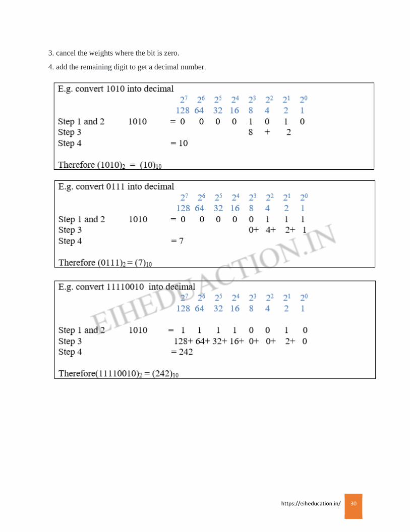
1 .write binary number
1. multiply each bit with the weight of each digit (bit) 20, 21, 22, 23 etc. 1,2,4,8,16…from right to left.
https://eiheducation.in/ 30
3. cancel the weights where the bit is zero.
4. add the remaining digit to get a decimal number.

https://eiheducation.in/ 31
Decimal to Binary: The conversion is done in several ways. One way to convert given decimal
number into binary is the reverse of the process seen above. The number is expressed as a sum of
power of two and then 1’s and 0’s are written at appropriate positions.
The second method is called as Double-Dabble method is easy and more frequently used. The
procedure is as follows.
1.Divide the given number successively by 22
2.write down the quotients directly below the given number.
3.write down the remainders on the right side.
4.the remainders taken in reverse order from bottom to top from the number.
The last quotient obtained by dividing 2 by 2 is 1. This 1 is not divisible by 2. Hence the next
quotient is 0 and 1 is transferred to remainders.
Hexadecimal number system: Hexadecimal numbers are extensively used in microprocessor work.
To begin with they are much shorter than binary numbers.
https://eiheducation.in/ 32
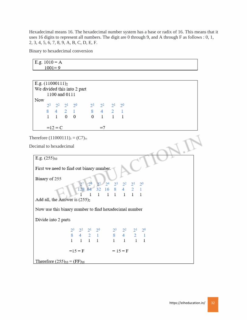
Hexadecimal means 16. The hexadecimal number system has a base or radix of 16. This means that it
uses 16 digits to represent all numbers. The digit are 0 through 9, and A through F as follows : 0, 1,
2, 3, 4, 5, 6, 7, 8, 9, A, B, C, D, E, F.
Binary to hexadecimal conversion
Therefore (11000111)2 = (C7)16
Decimal to hexadecimal
https://eiheducation.in/ 33
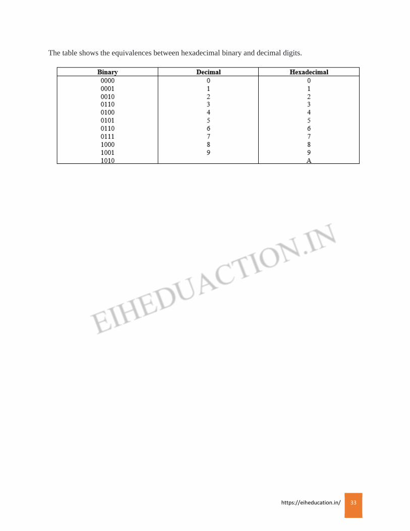
The table shows the equivalences between hexadecimal binary and decimal digits.
https://eiheducation.in/ 34
PROTOCOLS
DNS, HTTP, TFTP
Domain Name Service (DNS):
DNS is an internet service that translates domain names into IP address. Because domain names are
alphabetic, they’re easier to remember. The internet however, is really based on IP address. Every time
you use a domain name, a DNS service translate the name into the corresponding IP address. For
example, the domain name www.eihtech.com might translate to 23.229.193.162. The DNS protocol use
port number 53.
A domain is a subtree of the domain name space. From the root, few of the assigned top-level domains
are:
GOV = Government body.
EDU = Educational body.
NET = Networks
COM = Commercial entity.
MIL = U.S. Military.
ORG = Any other organization not previously listed.
DNS names are assign through the Internet Registries by the Internet Assigned Number Authority
(IANA).
Hypertext Transfer Protocol (HTTP):
The HTTP is an application protocol for distributed, collaborative, hypermedia information systems.
HTTP is the foundation of data communication for the World Wide Web. HTTP protocol uses port
number 80. Hypertext is structured text that uses logical link i.e. hyperlinks, between nodes containing
text. HTTP is the protocol to exchange o transfer hypertext.
It is uses to make a request from the client to the web servers that open the right resource when you click
on a link or type a URL in the web browser, whenever that resource may actually reside.
Trivial File Transfer Protocol (TFTP):
Trivial File Transfer Protocol is a simple version of FTP that allows a client to get from or put a file
onto a remote host. TFTP is a simple protocol for transferring files, implemented on top of the UDP/IP
protocols using well-known port number 69. One of its primary uses is in the early stages of booting from
a local area network, because TFTP is very simple to implement. TFTP lacks security and most of the
advanced featured offered by more robust file transfer protocols such as File Transfer Protocol.
TFTP protocol cannot be use for directory browsing; it can do nothing but only send and receive files.
This protocol sends smaller block of data as compared to FTP without any authentication access hence it
is insecure due to which it is less supported or used in site.
https://eiheducation.in/ 35
FTP, NFS, POP
File Transfer Protocol:
The FTP is a standard network protocol used to transfer computer files from one host to another host
over a TCP-based network, such as the Internet. It uses port number 21.
FTP is built on server-client architecture and uses separate control and data connection between the client
and the server.
FTP uses many authenticate themselves with a clear-text sign-in protocol, normally in the form of a
username and password, but can connected anonymously if the server is configured to allow it.
Network File System (NFS):
NFP is a distributed file system protocol allowing a user on a client computer to access file over a
network much like a local storage access. It allows two different types of file system to interoperate. It has
different version: NFS2, NFS3 and NFS4. NFS protocol uses port number 2049.
In NFS environment, a Windows server running NFS Server Software and the UNIX host running the
NFS client software allows to store the UNIX file which can be access by UNIX users. Hence both UNIX
users and Windows users with Windows file system and UNIX file system can access that same file with
their normal file system, in their normal way.
Post Office Protocol (POP):
In computing, the POP is an application-layer Internet standard protocol user by local e-mails clients
to retrieve email from a remote server over a TCP/IP connection. It is also known as incoming address.
POP has been developed through several versions with version 3 (POP3) being the latest one.
Email clients using POP generally connect, retrieve all messages, store them on the user’s PC as new
message, delete them from the server, and then disconnect. Most POP clients have an option to leave mail
on server after the download.
A POP3 server listens on well-known port 110 or Secure Socket Layer (SSL) on well-known port 995.
https://eiheducation.in/ 36
IMAP, SMTP, SSL
Internet Message Access Protocol, version 4 (IMAP4):
In computing, The IMAP is an internet standard protocol used by email clients to retrieve email
messages from a mail server over a TCP/IP connection. The current version of IMAP is version 4. IMAP
was designed with the goal of permitting complete management of an email box by multiple email clients;
therefore, clients generally leave message on the server until the user explicitly deletes them. An IMAP
server typically listens on port number 143. IMAP over SSL (IMAPS) is assigned the port number 993.
Simple Mail Transfer Protocol (SMTP):
SMTP known as outgoing address is an Internet standard protocol for electronic mail transmission
where mail are send from client to mail server. SMTP is used to send mail; POP3 is used to receive mail,
SMTP by default uses TCP port 25 and when secured by SSL also known as SMTPS uses default port
465.
Although electronic mail servers and other mail transfer agents use SMTP to send and receive mail
messages, user-level client mail applications typically use SMTP only for sending messages to a mail
server for relaying.
Transport Layer Security (TLS)/Secure Socket Layer(SSL):
TLS and its predecessor, SSL both of which are frequently referred to as SSL. TLS are cryptographic
protocols that are used to enabling secure online data transfer processes such as surfing the web sites,
downloading form site, sending messages across network, etc.
Most web sites use TLS for setting secure communication between their servers and web browsers client.
The primary goal of the TLS protocol is to provide privacy and data integrity between two
communicating computer applications.

https://eiheducation.in/ 37
SNMP, Telnet, SSH
Simple Network Management Protocol (SNMP):
SNMP used to collect and manipulates information about network components. It collects
information by selecting devices on the network from a central network management console using
SNMP messages at fixed or random intervals. Devices that typically support SNMP include routers,
switches, servers, workstations, printers, modem racks and more.
Telnet:
Telnet is an application layer protocol used on the internet or local area network to provide a
bidirectional interactive text oriented communication facility using a virtual terminal connection. This
protocol is used to establish a connection to Transmission Control Protocol port number 23.
Secure shell (SSH):
SSH is a cryptographic encrypted network protocol to allow remote login and other networks service
to operate securely over an unsecured network. SSH provide a secure channel over an unsecured network
in a client server architecture, connecting an SSH client application with an SSH server. Common
applications include remote command-line login and remote command execution, but any network service
can be executed with SSH. The protocol specification distinguished between two major version, referred
as SSH-1 and SSH-2.
The standard TCP port 22 has been assigned for contacting SSH servers. SSH was designed as a
replacement for Telnet and for unsecured remote shell protocols. There are many application used for
SSH for example: Putty, OpenSSH, Chrome Secure Shell, etc.
https://eiheducation.in/ 38
BACKBONE
IP Addressing
An IP address is a 32 bit number assigned to each host on a network. It is a combination of Network
ID and Host ID. It is launched by IANA- Internet Assigned Number Authority. IANA is a department
of ICANN (Internet Corporation for Assigned Names and Numbers) is the private (non-government)
non-profit corporation with responsibility for IP address space allocation. An IP address is a software
(logical) address, not a hardware (physical) address. IP addressing was designed to allow host on one
network to communicate with the host on a different network.
An IP address is usually represented in dot-decimal notation, consisting of four-decimal numbers
separated by periods (e.g. 192.168.0.1). the first of the address usually represents a network device
(192.168.0.0), while the last part of the address identifies the host device (e.g. 192.168.0.1).
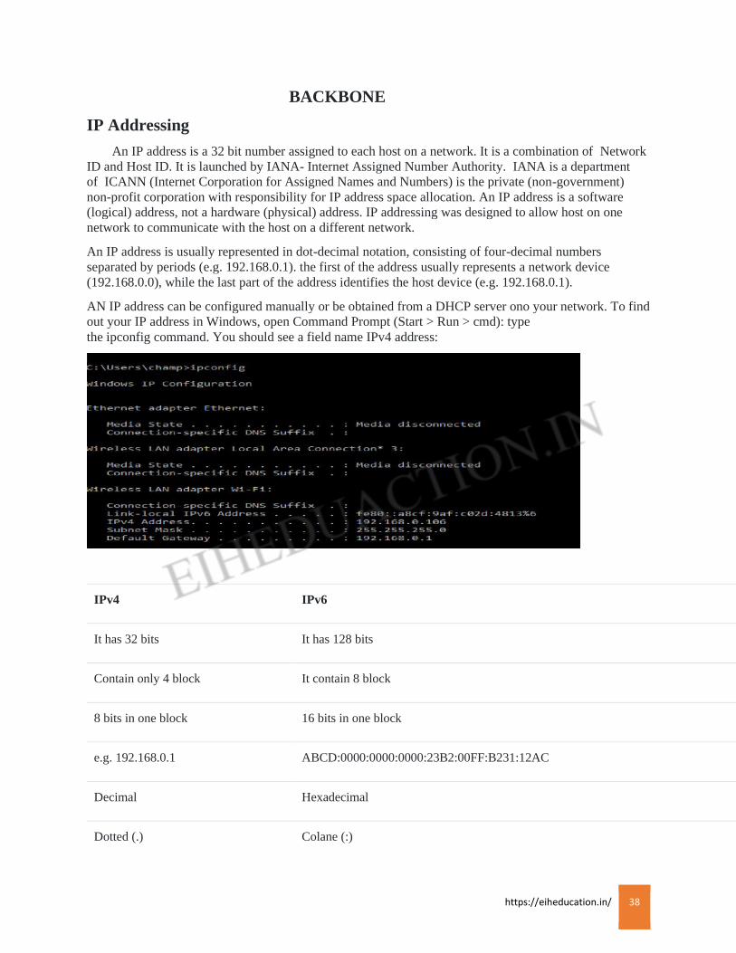
AN IP address can be configured manually or be obtained from a DHCP server ono your network. To find
out your IP address in Windows, open Command Prompt (Start > Run > cmd): type
the ipconfig command. You should see a field name IPv4 address:
IPv4 IPv6
It has 32 bits It has 128 bits
Contain only 4 block It contain 8 block
8 bits in one block 16 bits in one block
e.g. 192.168.0.1 ABCD:0000:0000:0000:23B2:00FF:B231:12AC
Decimal Hexadecimal
Dotted (.) Colane (:)

https://eiheducation.in/ 39
Classes of Addressing:
The developers of the internet planned to create classes of networks as per there network size. The
classes of network are:
Classes Network Range Use Leading Bits
A 0-127 (1-126 in use) Large network 1 (0)
B 128-191 Medium network 2 (10)
C 192-223 Small network 3 (110)
D 224-239 Multicast address 4 (1110)
E 240-255 R & D 4 (1111)

https://eiheducation.in/ 40
Class A:
The class A network and host combination is:
NETWORK.HOST.HOST.HOST
As Class A has first block or byte for network address so the total network ID in form of bits present for
class A is Network ID = 8 bits whereas for host ID there are 3 blocks i.e. Host ID = 3*8=24 bits.
In Class A the first bit of the first block or byte must always be off or 0.
i.e. 0xxxxxxx
here the x can replace by 0 or 1 , if we replace x with all 0 and then with 1, then we will find the range of
Class A network address:
00000000 = 0
01111111 = 127
Hence the range stand between 0 to 127 for Class A, but the complication is that the network address of
all 0’s i.e. 00000000 is reserved for default route and the 127 is reserved for loopback address used for
diagnostics, thus this both number cannot be used for specifying Class A network address.
Hence Class A range is 1 to 126.
With the first bit of the first byte reserved there remain the 7 bit out of 8 for addressing. As a result the
total network that can be obtained from Class A is: 27=128
Here from 128 we have to minus 2 as 0 and 127 not used as they are reserved. So total is 128-2=
126network.
Class A has 3 bytes for host address, so that total host address found in class A is:
224-2= 1,67,77,214 host
Here 2 minus is the two address which are the network address and the broadcast address
Example of identify the valid host address in a Class A network address:
All host bits off = network address: 20.0.0.0
All host bits on = broadcast address: 20.255.255.255
The valid host are the address that are in between the network address and the broadcast address i.e.
starting from 20.0.0.1 to 20.255.255.254. An important thing to remember is that 0s and 255s can be valid
host address, such that host bits cant ever be all turned off or all turned on at the same time.
Class B:
The Class B network and host combination is:
NETWORK.NETWORK.HOST.HOST
As Class B has first two block for network address so the total network ID in form of bits present for
Class B is Network ID =2*8 = 16 bits whereas for host ID there are two blocks i.e. Host ID = 2*8= 16
bits
In Class B that RFCs state that the first bit of the first byte must always be turned on or set to 1 and the
second bit to off or 0.
https://eiheducation.in/ 41
i.e. 10xxxxxx
here the x can replace by 0 or 1 , if we replace x with all 0 and then with 1, then we will find the range of
Class B network address:
10000000 = 128
10111111 = 191
Hence the range of Class B is 128 to 191.
With the network address of 2 bytes where network address start with binary digit 1 then 0 thus 2 bit mins
from the first 2 byte i.e. 16 bits leaves with 14 bit for addressing. As a result the total network that can be
obtained from Class B is: 214=16384 network
Class B has 2 bytes for host address, so that total host address found in Class B is: 216-2= 65534host.
Here also the minus 2 is the two address which are the network address and the broadcast address.
Example to identify the valid host address in a Class A network address:
All host bits off = network address: 172.18.0.0
All host bits on = broadcast address: 172.18.255.255.
The valid host are the address that are in between the network address and the broadcast address i.e.
starting from 172.18.0.1 and ending with 172.18.255.251.
Class C:
The Class C network and host combination is:
NETWOR.NETWORK.NETWORK.HOST
As Class C has first 3 byte for network address so the total network ID in form of bits present for Class C
is Network ID =3*8 = 24 bits whereas for Host ID there are 1 bytes so Host ID= 8 bits.
In class C that RFCs state that the first 3 bit of the first byte must always be turned on or set to 1 and the
third bit to off or 0.
i.e. 110xxxxx
here the x can replace by 0 or 1 , if we replace x with all 0 and then with 1, then we will find the range of
Class C snetwork address:
11000000 = 192
11011111 = 223
Thus the range of Class C is 192 to 223.
In Class C network address, the first 3 bit is set to the binary 110. So first 3 bytes or 24 bits NID minus 3
bit leaves with 21 bits. As a result the total network that can be obtained from Class C is:
221=2,097,152 network
Class C has byte for host address, so that total host address found in Class C is: 28-2=254 host
Similarly minus 2 is the 2 address which are the network address and the broadcast address.
https://eiheducation.in/ 42
Example to identify the valid host address in a Class A network address:
All host bits off= network address: 192.168.0.0
All host bits on = broadcast address: 192.168.255.255.
The valid hosts are the addresses that are in between the network address and the broadcast address i.e.
starting from 192.168.0.1 to 192.168.255.254.
Class D
In Class D that RFCs state that the first 4 bit of the first byte must always be turned on or set to 1, so
considering the following network address:
i.e. 1110xxxx
here the x can replace by 0 or 1 , if we replace x with all 0 and then with 1, then we will find the range of
Class D network address:
11100000 = 224
11101111 = 239
The address 224 to 239 is range of Class D which used for multicast address.
Class E
The remaining range i.e. from 240 to 255 is of Class E, which is used for research and development.
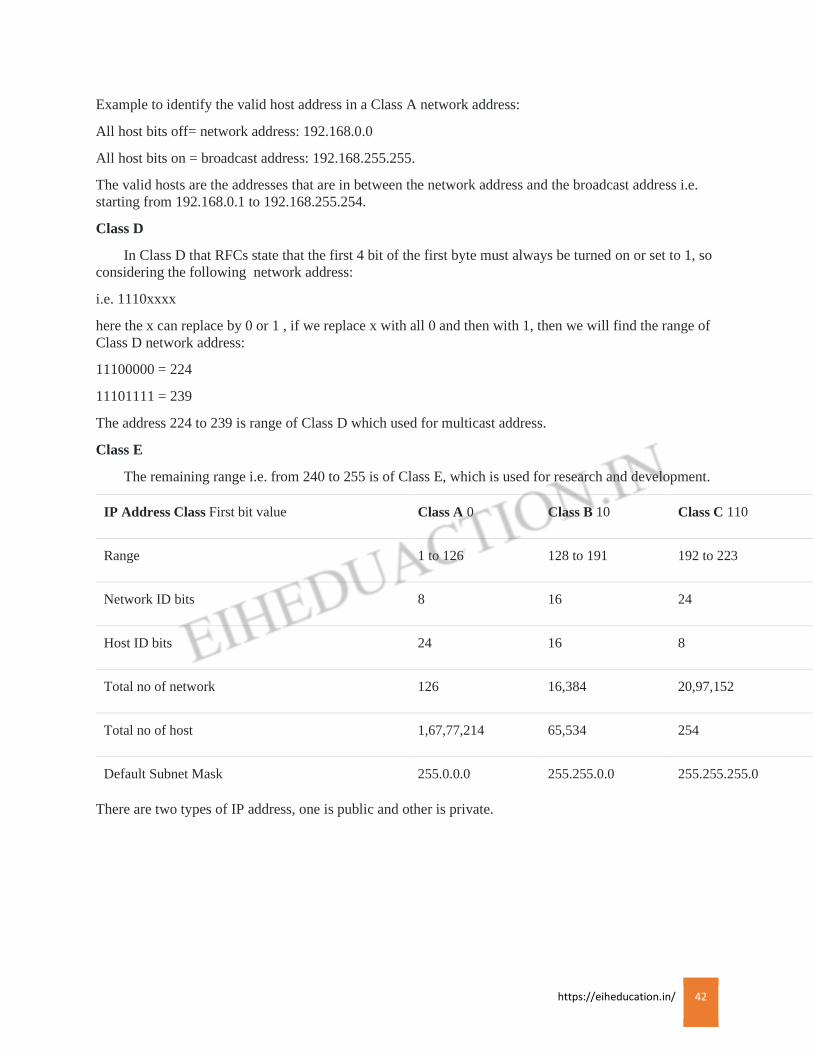
IP Address Class First bit value Class A 0 Class B 10 Class C 110
Range 1 to 126 128 to 191 192 to 223
Network ID bits 8 16 24
Host ID bits 24 16 8
Total no of network 126 16,384 20,97,152
Total no of host 1,67,77,214 65,534 254
Default Subnet Mask 255.0.0.0 255.255.0.0 255.255.255.0
There are two types of IP address, one is public and other is private.
https://eiheducation.in/ 43
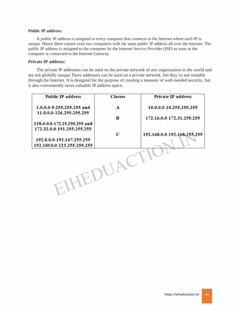
Public IP address:
A public IP address is assigned to every computer that connects to the Internet where each IP is
unique. Hence there cannot exist two computers with the same public IP address all over the Internet. The
public IP address is assigned to the computer by the Internet Service Provider (ISP) as soon as the
computer is connected to the Internet Gateway.
Private IP address:
The private IP addresses can be used on the private network of any organization in the world and
are not globally unique.There addresses can be used on a private network, but they’re not routable
through the Internet. It is designed for the purpose of creating a measure of well-needed security, but
it also conveniently saves valuable IP address space.
https://eiheducation.in/ 44
Subnetting
Subnetting
Subnetting is logically dividing the network by extending the 1’s used in Subnet Mask.
Subnetting allows you to create multiple logical networks that exist within a single class A,B or C
network. If you do not subnet, you are only able to use one network from your class A,B or C
network. In other language, subnetting is one network divided into the different different network.
Subnetting reduce the wastage of IP address. It increase the number of network and reduce the
number of host.
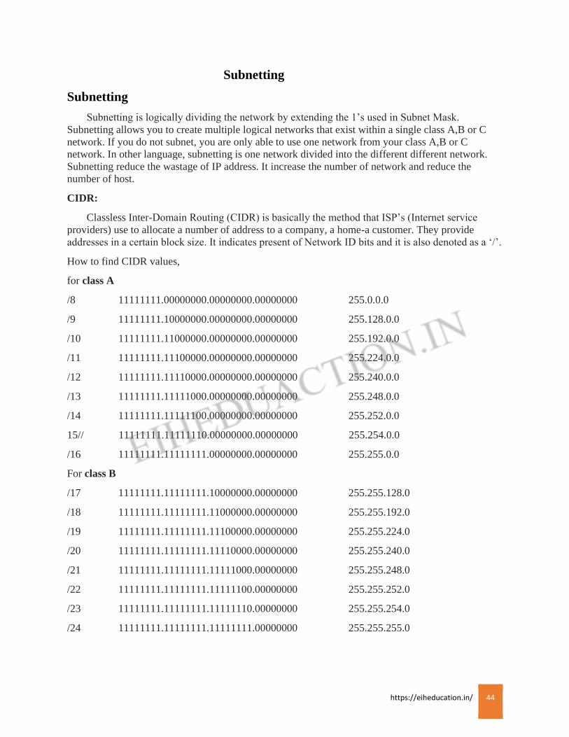
CIDR:
Classless Inter-Domain Routing (CIDR) is basically the method that ISP’s (Internet service
providers) use to allocate a number of address to a company, a home-a customer. They provide
addresses in a certain block size. It indicates present of Network ID bits and it is also denoted as a ‘/’.
How to find CIDR values,
for class A
/8 11111111.00000000.00000000.00000000 255.0.0.0
/9 11111111.10000000.00000000.00000000 255.128.0.0
/10 11111111.11000000.00000000.00000000 255.192.0.0
/11 11111111.11100000.00000000.00000000 255.224.0.0
/12 11111111.11110000.00000000.00000000 255.240.0.0
/13 11111111.11111000.00000000.00000000 255.248.0.0
/14 11111111.11111100.00000000.00000000 255.252.0.0
15// 11111111.11111110.00000000.00000000 255.254.0.0
/16 11111111.11111111.00000000.00000000 255.255.0.0
For class B
/17 11111111.11111111.10000000.00000000 255.255.128.0
/18 11111111.11111111.11000000.00000000 255.255.192.0
/19 11111111.11111111.11100000.00000000 255.255.224.0
/20 11111111.11111111.11110000.00000000 255.255.240.0
/21 11111111.11111111.11111000.00000000 255.255.248.0
/22 11111111.11111111.11111100.00000000 255.255.252.0
/23 11111111.11111111.11111110.00000000 255.255.254.0
/24 11111111.11111111.11111111.00000000 255.255.255.0

https://eiheducation.in/ 45
For class C
/25 11111111.11111111.11111111.10000000 255.255.255.128
/26 11111111.11111111.11111111.11000000 255.255.255.192
/27 11111111.11111111.11111111.11100000 255.255.255.224
/28 11111111.11111111.11111111.11110000 255.255.255.240
/29 11111111.11111111.11111111.11111000 255.255.255.248
/30 11111111.11111111.11111111.11111100 255.255.255.252
We can’t use a /31 or /32 because we have at least 2 host bit for assigning IP addresses to hosts.
How to find subnetting
How many subnet?
How many valid host per subnet?
What are the valid subnet ( block size)?
What are the broadcast address for each subnet?
What are the valid host?
You have to learn this table:
27 26 25 24 23 22 21 20
128 64 32 16 8 4 2 1
Example of class C: 192.168.10.0/26
Note: change occur in 4th octet.
Network address = 192.168.10.0
Subnet mask = 255.255.255.192
We have to solve all five questions mention above.
How many subnet: 2n n: number of network (on bit i.e. 1)
22 = 4 (192 – 11000000 i.e. only 2 on bits)
How many hosts per subnet: 2H-2 h: number of Host(off bit i.e.0)
26-2 = 62 (11000000 i.e. 6 off bits)
What are the valid subnet: 256-192 = 64 . (we start at zero and count in our block size, so
subnets are 0, 64, 128, and 192.
What is the broadcast address for each subnet: the number right before the value of the next subnet is
all hosts bits turned on and equals the broadcast address. For the zero subnet the next subnet is 64, so
the broadcast address for the zero subnet is 63. In general broadcast address is last host of the block,
for zero to 64 block (i.e. one block) last host is 63.
https://eiheducation.in/ 46
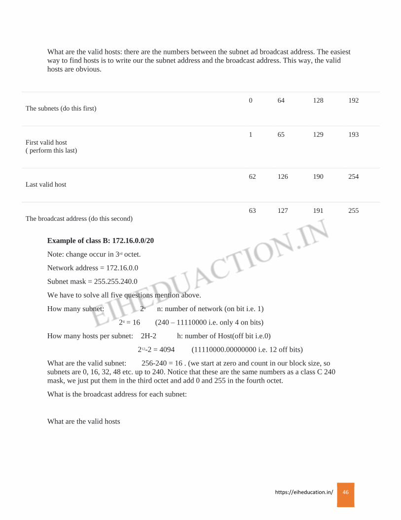
What are the valid hosts: there are the numbers between the subnet ad broadcast address. The easiest
way to find hosts is to write our the subnet address and the broadcast address. This way, the valid
hosts are obvious.
The subnets (do this first)
0 64 128 192
First valid host
( perform this last)
1 65 129 193
Last valid host
62 126 190 254
The broadcast address (do this second)
63 127 191 255
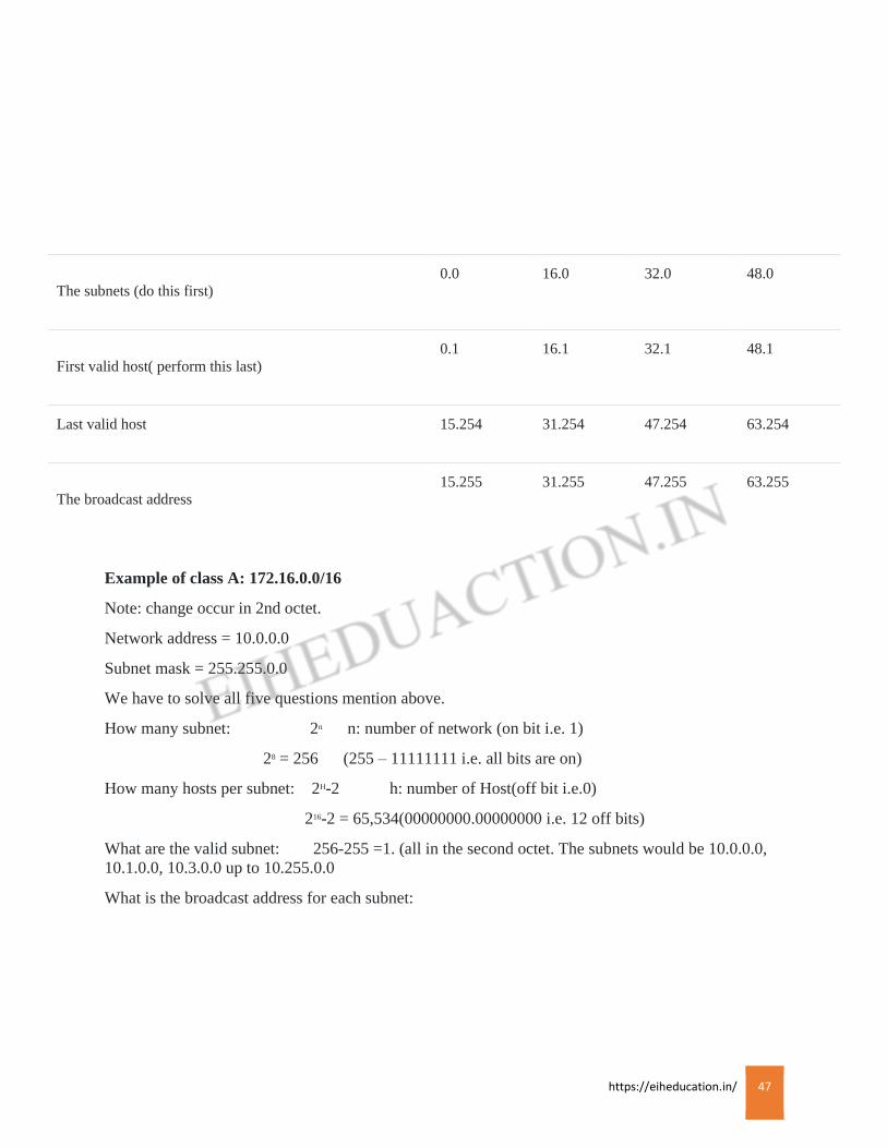
Example of class B: 172.16.0.0/20
Note: change occur in 3rd octet.
Network address = 172.16.0.0
Subnet mask = 255.255.240.0
We have to solve all five questions mention above.
How many subnet: 2n n: number of network (on bit i.e. 1)
24 = 16 (240 – 11110000 i.e. only 4 on bits)
How many hosts per subnet: 2H-2 h: number of Host(off bit i.e.0)
212-2 = 4094 (11110000.00000000 i.e. 12 off bits)
What are the valid subnet: 256-240 = 16 . (we start at zero and count in our block size, so
subnets are 0, 16, 32, 48 etc. up to 240. Notice that these are the same numbers as a class C 240
mask, we just put them in the third octet and add 0 and 255 in the fourth octet.
What is the broadcast address for each subnet:
What are the valid hosts
https://eiheducation.in/ 47
The subnets (do this first)
0.0 16.0 32.0 48.0
First valid host( perform this last)
0.1 16.1 32.1 48.1
Last valid host 15.254 31.254 47.254 63.254
The broadcast address
15.255 31.255 47.255 63.255
Example of class A: 172.16.0.0/16
Note: change occur in 2nd octet.
Network address = 10.0.0.0
Subnet mask = 255.255.0.0
We have to solve all five questions mention above.
How many subnet: 2n n: number of network (on bit i.e. 1)
28 = 256 (255 – 11111111 i.e. all bits are on)
How many hosts per subnet: 2H-2 h: number of Host(off bit i.e.0)
216-2 = 65,534(00000000.00000000 i.e. 12 off bits)
What are the valid subnet: 256-255 =1. (all in the second octet. The subnets would be 10.0.0.0,
10.1.0.0, 10.3.0.0 up to 10.255.0.0
What is the broadcast address for each subnet:

https://eiheducation.in/ 48
What are the valid hosts:
The subnets (do this first)
10.0.0.0
10.1.0.0
10.255.0.0
First valid host
10.0.0.1
10.1.0.1
10.255.0.1
Last valid host
10.0255.254
10.1.255.254
10.255.254.255
The broadcast address
10.0.255.255
10.1.255.255
10.255.255.255
https://eiheducation.in/ 49
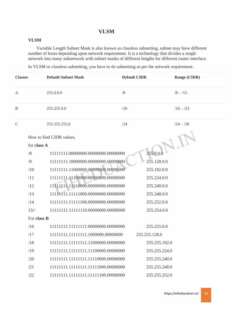
VLSM
VLSM
Variable Length Subnet Mask is also known as classless subnetting, subnet may have different
number of hosts depending upon network requirement. It is a technology that divides a single
network into many subnetwork with subnet masks of different lengths for different router interface.
In VLSM or classless subnetting, you have to do subnetting as per the network requirement.
Classes Default Subnet Mask Default CIDR Range (CIDR)
A 255.0.0.0 /8 /8 – /15
B 255.255.0.0 /16 /16 – /23
C 255.255.255.0 /24 /24 – /30
How to find CIDR values,
for class A
/8 11111111.00000000.00000000.00000000 255.0.0.0
/9 11111111.10000000.00000000.00000000 255.128.0.0
/10 11111111.11000000.00000000.00000000 255.192.0.0
/11 11111111.11100000.00000000.00000000 255.224.0.0
/12 11111111.11110000.00000000.00000000 255.240.0.0
/13 11111111.11111000.00000000.00000000 255.248.0.0
/14 11111111.11111100.00000000.00000000 255.252.0.0
15// 11111111.11111110.00000000.00000000 255.254.0.0
For class B
/16 11111111.11111111.00000000.00000000 255.255.0.0
/17 11111111.11111111.1000000.00000000 255.255.128.0
/18 11111111.11111111.11000000.00000000 255.255.192.0
/19 11111111.11111111.11100000.00000000 255.255.224.0
/20 11111111.11111111.11110000.00000000 255.255.240.0
/21 11111111.11111111.11111000.00000000 255.255.248.0
/22 11111111.11111111.11111100.00000000 255.255.252.0
https://eiheducation.in/ 50
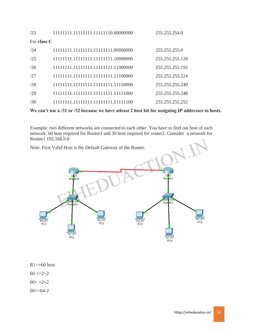
/23 11111111.11111111.11111110.00000000 255.255.254.0
For class C
/24 11111111.11111111.11111111.00000000 255.255.255.0
/25 11111111.11111111.11111111.10000000 255.255.255.128
/26 11111111.11111111.11111111.11000000 255.255.255.192
/27 11111111.11111111.11111111.11100000 255.255.255.224
/28 11111111.11111111.11111111.11110000 255.255.255.240
/29 11111111.11111111.11111111.11111000 255.255.255.248
/30 11111111.11111111.11111111.11111100 255.255.255.252
We can’t use a /31 or /32 because we have atleast 2 host bit for assigning IP addresses to hosts.
Example: two different networks are connected to each other. You have to find out host of each
network. 60 host required for Router1 and 30 host required for router2. Consider a network for
Router1 192.168.0.0
Note: First Valid Host is the Default Gateway of the Router.
R1<=60 host
60 <=2n-2
60< =26-2
60<=64-2

https://eiheducation.in/ 51
60<=62
Now total number of network bits=32 (a network contain 32 bits)
=32 – n = 32-6 = 26
This 26 is your CIDR value of the network 192.168.0.0
That means 192.168.0.0/26
N.S.M 11111111.11111111.1111111.11000000
255.255.255.192
Block size= 256-192
= 64
192.168.0.0 Network ID
192.168.0.1 First Valid Host
192.168.0.62 Last Valid Host
192.168.0.63 Broadcast address
192.168.0.64 New Network(Router2)
R2<=30 hosts
30<=2n-2
30<=25-2
30<=32-2
30<=30
Now total number of network bits= 32
=32- n = 32-5 =27
This 27 is the CIDR value of network 192.168.0.64
That means 192.168.0.64/27
N.S.M 11111111.11111111.11111111.11100000
255.255.255.224
Block size = 256- N.S.M
= 256-224 = 32
192.168.0.64 Network ID
192.168.0.65 First Valid Host
192.168.0.94 Last Valid Host
192.168.0.95 Broadcast Address

https://eiheducation.in/ 52
192.168.0.96 New Network for R1 and R2
R1 & R2 <= 2 (we want only two host to connect both router to the 3rd network)
3rd network is formed between two routers.
2<= 2n-2
2<=22-2
2<=4-2
2<=2
Now total number of network bits= 32
=32 – n = 32 – 2 = 30
This 30 is the CIDR value of network 192.168.0.96
That means 192.168.0.96/30
N.S.M 11111111.11111111.11111111.11111100
255.255.255.252
Block size = 256-252
= 4
192.168.0.96 Network ID
192.168.0.97 First Valid Host
192.168.0.98 Last Valid Host
192.168.0.99 Broadcast address
192.168.0.100 New Network (this network can be used for further connection)
https://eiheducation.in/ 53
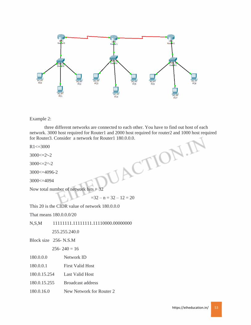
Example 2:
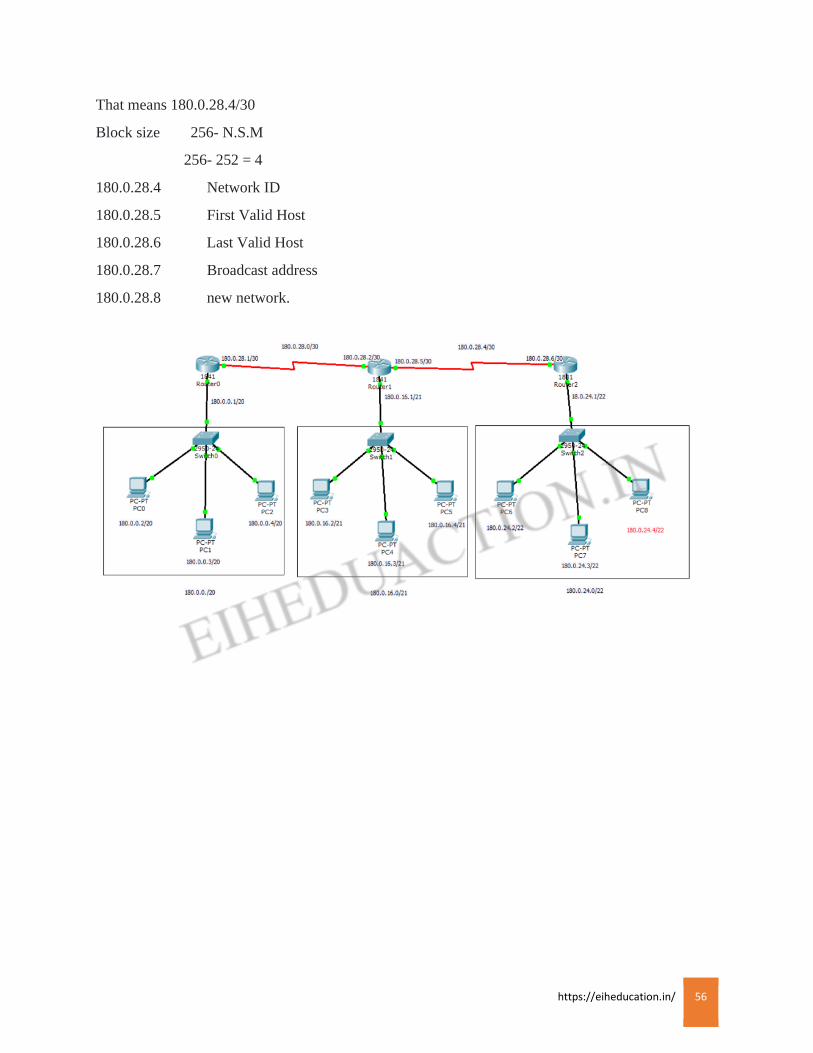
three different networks are connected to each other. You have to find out host of each
network. 3000 host required for Router1 and 2000 host required for router2 and 1000 host required
for Router3. Consider a network for Router1 180.0.0.0.
R1<=3000
3000<=2n-2
3000<=212-2
3000<=4096-2
3000<=4094
Now total number of network bits = 32
=32 – n = 32 – 12 = 20
This 20 is the CIDR value of network 180.0.0.0
That means 180.0.0.0/20
N,S,M 11111111.11111111.11110000.00000000
255.255.240.0
Block size 256- N.S.M
256- 240 = 16
180.0.0.0 Network ID
180.0.0.1 First Valid Host
180.0.15.254 Last Valid Host
180.0.15.255 Broadcast address
180.0.16.0 New Network for Router 2

https://eiheducation.in/ 54
R2<= 2000
2000<=2n-2
2000<=211-2
2000<=2048-2
2000<=2046
Now total number of network bits = 32
= 32- n = 32 – 11 = 21
This 21 is the CIDR value of 180.0.0.16
That means 180.0.0.16/21
N.S.M 11111111.11111111.11111000.00000000
255.255.248.0
Block size 256- N.S.M
256-248 = 8
180.0.16.0 Network ID
180.0.16.1 First Valid Host
180.0.23.254 Last Valid Host
180.0.23.255 Broadcast address
180.0.24.0 New Network for Router 3
R3<=1000
1000<=2n-2
1000<=210-2
1000<=1024-2
1000<=1022
Now total number of network bits = 32
= 32- n = 32- 10 = 22
This 22 is the CIDR value of 180.0.0.24
That means 180.0.0.24/22
N.S.M 11111111.11111111.11111100.00000000
255.255.252.0
Block size 256-N,S,M
256-252 = 4
https://eiheducation.in/ 55
180.0.24.0 Network ID
180.0.24.1 Frist Valid Host
180.0.27.254 Last Valid Host
180.0.27.255 Broadcast address
180.0.28.0 New Network for Router 1 and Router 2
R1 & R2<=2
2<=2n-2
2<=22-2
2<=4-2
2<=2
Now total number of network bits = 32
= 32- n = 32 – 2 = 30
This 30 is the CIDR value of 180.0.28.0
That means 180.0.28.0/30
N.S.M 11111111.11111111.11111111.11111100
255.255.255.252
Block size 256- N.S.M
256- 252 = 4
180.0.28.0 Network ID
180.0.28.1 First Valid Host
180.0.28.2 Last Valid Host
180.0.28.3 Broadcast address
180.0.28.4 New Network for Router 2 and Router 3
R2 & R3 <=2
2<=2n-2
2<=22-2
2<=4-2
2<=2
Now total number of network bits = 32
= 32 – n = 32 – 2 = 30
This 30 is the CIDR value of network 18.0.28.4
https://eiheducation.in/ 56
That means 180.0.28.4/30
Block size 256- N.S.M
256- 252 = 4
180.0.28.4 Network ID
180.0.28.5 First Valid Host
180.0.28.6 Last Valid Host
180.0.28.7 Broadcast address
180.0.28.8 new network.
https://eiheducation.in/ 57
Summarization
Summarization
The process of taking a range of IP addresses and advertising them in one address block is
known as summarization or route summarization. Its allow routing protocol to advertise to many
network as one address. The purpose of this is to reduce the size of routing table on the router to save
the memory.
There are two types of summarization
1. Automatic 2) Manually
Example,
192.168.1.0/24
192.168.2.0/24
192.168.3.0/24
192.168.4.0/24
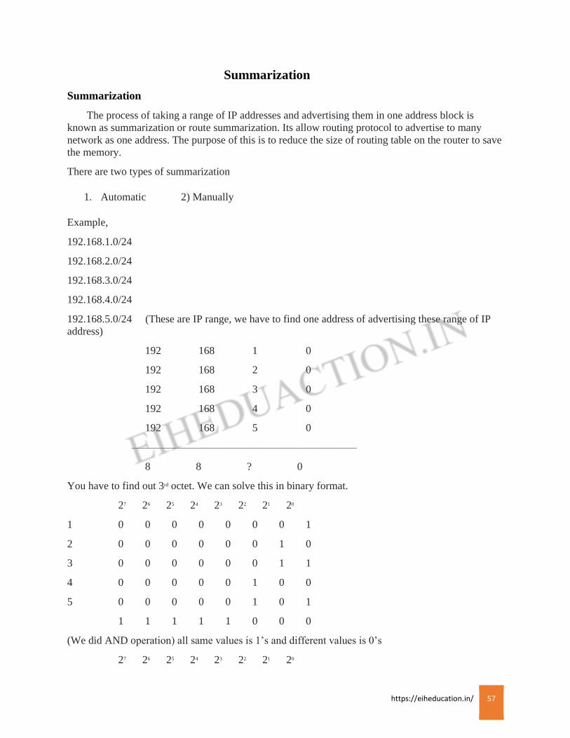
192.168.5.0/24 (These are IP range, we have to find one address of advertising these range of IP
address)
192 168 1 0
192 168 2 0
192 168 3 0
192 168 4 0
192 168 5 0
—————————————————————
8 8 ? 0
You have to find out 3rd octet. We can solve this in binary format.
27 26 25 24 23 22 21 20
1 0 0 0 0 0 0 0 1
2 0 0 0 0 0 0 1 0
3 0 0 0 0 0 0 1 1
4 0 0 0 0 0 1 0 0
5 0 0 0 0 0 1 0 1
1 1 1 1 1 0 0 0
(We did AND operation) all same values is 1’s and different values is 0’s
27 26 25 24 23 22 21 20
https://eiheducation.in/ 58
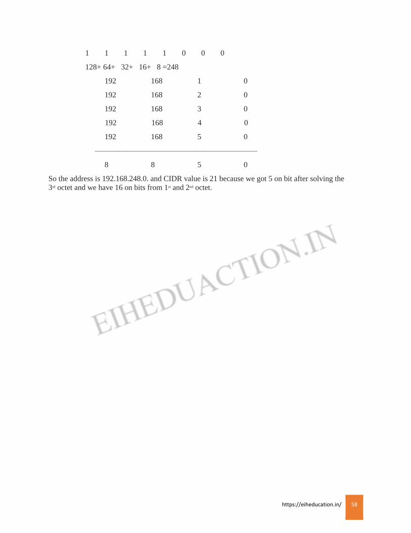
1 1 1 1 1 0 0 0
128+ 64+ 32+ 16+ 8 =248
192 168 1 0
192 168 2 0
192 168 3 0
192 168 4 0
192 168 5 0
—————————————————————
8 8 5 0
So the address is 192.168.248.0. and CIDR value is 21 because we got 5 on bit after solving the
3rd octet and we have 16 on bits from 1st and 2nd octet.

https://eiheducation.in/ 59
ROUTER
Router and IOS
A router is a networking device that forwards data packets between computer networks. A
data packet is typically forwarded from one router to another router through the networks that
constitute an internetwork until it reaches its destination node.
Function of Router:
Packet forwarding: Packetsare transferred between a source interface and a destination interface,
usually on two different systems
Packet switching:
Internetwork connection
Packet filtering
Path selection
Type of Router:
Cisco router is available in two type non-modular and modular.
Non-modular routers are low cost routers with fixed interface or cards. If we want to add ports or
interfaces later on we cannot add them,
Modular routers are those routers which can extend with certain component, such as interfaces or
ports. Hence we can add interface cards later on,
Rules to configure Router:
Cisco router and switches support to types of external connection: Port and Interface.
Ports are used for configuration purpose and provide an out-of-bond management method that is
managing purpose without affecting traffic flowing through Cisco devices.
Interface are used to connect devices together like switch to router, router to router, PC to router.
Interface can be used for management purpose but it will affect the performance of the device.
You can access and configure a Cisco device in many ways including the following:
Console port
AUX port (only certain cisco product)
telnet
SSH
Web browser
SNMP management station.
The Cisco IOS is a Cisco proprietary software that is used on Cisco routers and switches. The IOS is
the kernel of Cisco routers and most switches. A kernel is the basic, indispensable part of an OS that
allocates resources and manages thigs such as low-level hardware interface and security. At first IOS
https://eiheducation.in/ 60
was developed by William Yeager in 1986, to provide network services and enable networked
applications.
Cisco router IOS software is responsible for
· Supporting and transferring network protocols.
· Adding security to strictly control access to network and networking devices to stop
unauthorized access.
· Providing scalability for ease of network growth.
Providing network reliability to ensure that resources are always available and reachable.
Cisco router:
Cisco Router are internetworking devices used to connect different distinct
networks. Cisco router is available in two type non-modular and modular.
Non-modular routers are low cost routers with fixed interface or cards. If we want to add ports or
interfaces later on we cannot add them,
Modular routers are those routers which can extend with certain component, such as interfaces or
ports. Hence we can add interface cards later on,
Cisco routers support two types of connections such as ports and interfaces.
Ports are used for configuration purpose and provide an out-of-bond management method that is
managing purpose without affecting traffic flowing through Cisco devices.
Interface are used to connect devices together like switch to router, router to router, PC to router.
Interface can be used for management purpose but it will affect the performance of the device.
You can access the Cisco from console port of a router, from a modem into the auxiliary or AUX
port, or even through Telnet. Access to the IOScommand line is called a EXEC session,
https://eiheducation.in/ 61
Internal Component of Router
Internal Component of Router
Each IOS device has two main components: hardware and software. Almost every IOS based
router uses the same hardware and firmware component to assist using boot up process, include the
following ROM, RAM, NVRAM (non volatile), a configuration register, physical lines and
interfaces
ROM:
ROM is non volatile, contains the firmware necessary to boot up your router and typically has
following four components
POST :
performs tests on the routers hardware components
Bootstrap program :
Brings the router Up, and determines hows the IOS image and configuration file will be found
and will be loaded
ROMMON:
A mini operating system that allow you to perform low-level testing and troubleshooting, for e.g.
ROMMON is used during password recovery
MINI-IOS:
A stripped down version of the IOS contains only IP codes. This should be used in the
emergency situation when IOS in the flash cant be found and you want to boot up your router and
load in another IOS image, not every router has MINI-IOS image, stripped down IOS is referred to as
RXBOOT mode.
RAM :
Is like the memory in your PC, on a router, RAM contains the running IOS image, the active
configuration file, any tables including routing, arp tables. When you turn off router everything in
RAM is erased
FLASH:
Is a form of non volatile memory, Router stores their IOS image in flash, but other information
can also be stored here.
NVRAM:
Is like flash, Routers and switches use NVRAM to store their configuration file.
Configuration register is a special register in the router that determines many of its bootup and
running option, including how router finds the IOS image and its configuration file. Configuration
register is a part of NVRAM
https://eiheducation.in/ 62
Every router has at least one line and one physical interface. Line or ports are typically used for
management access; The console and Aux lines are the examples
Interface are used to move traffic through the router ; they can include the media type such as
Ethernet, fast ethernet, serial and others. These interfaces can be used during the boot up process
IOS provides function similar to that provided by Microsoft or linux: it control and manages the
hardware on which it is running. Basically the IOS provides the interface between you and hardware,
enabling you to execute command to configure and manage Cisco devices
Advantages of the IOS:
Features: The IOS includes a wide array of feature for protocol and function that provide
connectivity, scalability, reliability, and security solution for networks of any size
Connectivity: The IOS supports a variety of data link layer technologies for LAN and WAN
environments
Scalability: The IOS support both fixed and modular chassis platforms, enabling you to purchase
hardware to meet your needs
Reliability: To ensure that your critical resources are always reachable, Cisco has developed many
products and IOS features to provide chassis and network redundancy
Security: With IOS you can strictly control access to your networking devices in accordance with
your internal security policies.
https://eiheducation.in/ 63
Booting Sequence
Booting Sequence
Router load and run the POST (Located in ROM), testing the hardware component, including
memory and interfaces, then the boot strap program is loaded and executed. The boot strap program
finds and loads an IOS image : possible location of IOS images include Flash, TFTP server, or mini-
IOS in ROM. Once IOS is loaded, IOS attempt to find and load configuration file, which is normally
stored in NVRAM, if the IOS can not find configuration file, it starts up the system configuration
dialog, after the configuration is loaded you are present wit the CLI interface
Boot strap:
Program goes through the following steps when trying to locate the IOS and load the IOS image:
1) Examine the configuration register value. This value is set for four hexadecimal digits. If last digit
is in between 0x2 to 0xf, then the router proceed to the next step.
2)Examine the configuration file in NVRAM for boot system commands, which tells the boot strap
program to where to find the IOS.
3)If no boot system commands are found in the NVRAM , use the first valid IOS image found in the
flash
4) If there are no valid IOS images in a Flash, generate a TFTP local broadcast to locate TFTP server
5)If no TFTP server is found, load the mini-IOS in ROM (Rxboot mode)
6) If there is a mini-IOS in rom, then the mini-IOS is loaded and you are taken into RXboot mode;
otherwise, the router either retries finding the IOS images or loads ROMMON and goes in to the
ROMmonitor mode
Speed:-
Ethernet: – 10Mbps
Fast Ethernet: – 100Mbps
Gigabit Ethernet: – 1Gbps
10gigabit Ethernet: -10Gbps
Serial interface: -1.544Mbps
Console port: – 9.6kbps (9600bits per second.
https://eiheducation.in/ 64
Command modes in Router
User Exec Mode (User Mode):
User Mode is the first mode a user has access to after logging into the router. The user mode can
be identified by the > prompt following the router name. this mode allows the user to execute only
the basic commands, such as those that show the systems status. The router cannot be configured or
restarted from this mode.
The user mode can be identified as Router>
Privileged EXEC mode ( Privileged mode):
Privileged mode allows user to view the system configuration, restart the system and enter router
configuration mode. Privileged mode also allows all the commands that are available in user mode.
Privileged mode can be identified by the # prompt following the router name. from the user mode, a
user can change to Privileged mode by running “enable” command. Also we can keep a enable
password or enable secret to restrict access to Privileged mode. An enable secret password uses
stronger encryption where it is stored in the configuration file and it is more safe.
The Privileged mode can be identified as Router#
Global Configuration Mode:
This mode allows user to modify the running system configuration. From the Privileged mode a
user can move to configuration mode by running the “configure terminal” from privileged mode. To
exit configuration mode, the user can enter “end” command or press ctrl-z key combination.
The Global Configuration mode can be identified as Router(config)#
Configuration modes and submodes:
From the global configuration modes you can access various configuration modes or sumodes.
For example, to configure an interface on your device, you would have to access the mode of that
interface. The interface mode contain commands relevant to the interface being configured. For
example, to access the interface mode for the Fast Ethernet interface on a Cisco router, type the
interface FastEthernet 0/0 command from the global configuration mode
The submodes can be identified as Router(config-if)
To exit this mode, the user can enter “end” command or press ctrl-z key combination.
https://eiheducation.in/ 65
ROUTING
Routing
Sending a packet from one router to another router its means routing. It refers to the process of
selecting the shortest and the most reliable path intelligently over which it sends data to its ultimate
destination through the routing protocol. Routing protocol makes the distinction between hosts and
gateways. A host is the end system to which data is ultimately deliverable. A gateway is the router
that accomplishes the act of routing data between two networks. The routing process usually
forwards packets on the basis of routing tables, which maintain a record of the routes to various
network destinations. Thus constructing routing tables, which are held in the router’s memory, is
very important for efficient routing. Most routing algorithms use only one network path at a time.
Multipath routing techniques enable the use of multiple alternative paths.
Routing protocol:
Routing protocol are used between routers to determine paths and maintain routing tables.
Example: RIP, IGRP, EIGRP, OSPF, etc.
Routed protocol:
A routed protocol is a network layer protocol which can be used to send the user data from one
network to another. Routed protocol carries user traffic such as e-mails, file transfer etc. Example: IP,
IPX, AppleTalk, etc.
Types of Routing: There are three types of Routing.
• Static Routing
• Default Routing
• Dynamic Routing
Static Routing:
Static routing is f form of routing that occurs when a router uses a manually-configured routing
entry. Rather than information from a dynamic routing traffic. In many case, static routes are
manually configured by a network administrator by adding the entries into a routing table. Unlike
dynamic routing, static routes are fixed and do not change if the network is changed or reconfigured.
Advantages
• Static routing can be used to define an exit point from a router when no other routes are
available or necessary. This is called a default route.
• Static routing can be used for small network that require only one or two routes. This is often
more efficient since a link is not being wasted by exchanging dynamic routing information.
• Static routing Is often used as a complement to dynamic routing to provide a failsafe backup
in the event that a dynamic route is unavailable.
• Static routing Is often used to help transfer routing information from one routing protocol to
another that is known as routing redistribution.
https://eiheducation.in/ 66
Disadvantages
In many case, static routes are manually configured. This increases the potential of human
errors.
When there is a change in network or a failure occur between two statically define devices, traffic
will not be re-routed. Network is down until the failure is overcome or the static route is manually
reconfigured by an administrator.
Static routes must be configured on each router in the networks. This configuration can take a long
time if there are many routers.
Syntax: ip route[destination network]
[destination network mask]
[next-hop address or exit interface]
IP route: is the standard announcement of the static route command
Destination network: is the IP address of the network to include in the routing table.
Mask: is the mask of that network.
Next hop address: is the address of the next hop router that will receive packets from you and
forward then to the destined network.
Exit interface: instead of next hop address you can declare the exit interface on your router.
Command to enable static route:
Router A>enable
Router A# configuration terminal
Router A(config)# ip route 192.168.2.0 255.255.255.0 192.168.1.2
Static route can also be added by specifying the exit interface rather than the “next hop” IP address of
the router.
Router A(config)# ip route 192.168.2.0 255.255.255.0 serial 0/0/0
Administrative Distance (AD):
Administrative Distance define the cost or weight of the routing protocols. If multiple routes or
multiple routing protocols are config on a router you can defined which protocol or route to be used
for specific network.
Default Route:
Default routing is used in case of Stub network. A Stub network is a network, which has only
one outgoing interface to access all network. A router which has only one exit or outgoing interface
will always have one default gateway for any or all network. There is only one gateway for all
networks. It is applied on boundary and border routers and on remaining router are configured as a
static route. That means if there is three routers connected to each other, router one is your boundary
and router three is your border, remaining router that is router two can be configured as static route.
It add the router in the form of 0. It reduce the routing table.

https://eiheducation.in/ 67
Syntax: ip route 0.0.0.0 0.0.0.0. default-gateway.
The first portion 0.0.0.0 represents any network whereas the second portion 0.0.0.0 represents any
subnet mask. The last part is default gateway for outgoing traffic.
Router A(config)# ip router 0.0.0.0 0.0.0.0 192.168.1.2
Dynamic Routing:
Dynamic routing is a alternate method of routing. This method uses layer-3 protocols to
automatically find neighboring routers and creates or updates routing table on routers. This method is
easy to configure and maintain, but however this method is resource intensive i.e. they requires more
CPU process, memory and bandwidth of router. Dynamic routing protocols are used in large
networks. Dynamic routing protocols are classified into 2 categories.
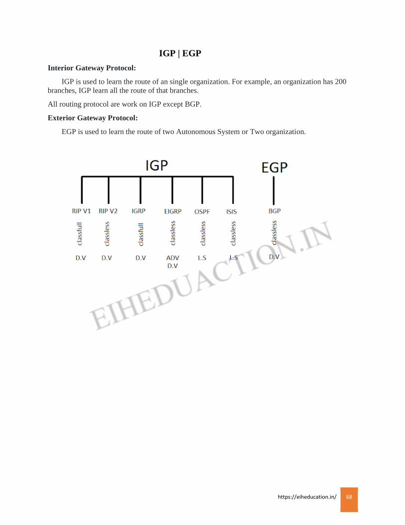
https://eiheducation.in/ 68
IGP | EGP
Interior Gateway Protocol:
IGP is used to learn the route of an single organization. For example, an organization has 200
branches, IGP learn all the route of that branches.
All routing protocol are work on IGP except BGP.
Exterior Gateway Protocol:
EGP is used to learn the route of two Autonomous System or Two organization.
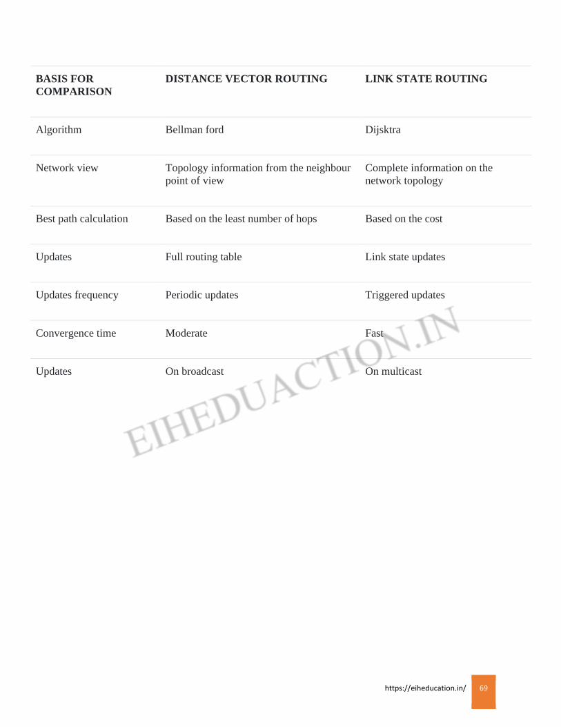
https://eiheducation.in/ 69
BASIS FOR
COMPARISON
DISTANCE VECTOR ROUTING LINK STATE ROUTING
Algorithm Bellman ford Dijsktra
Network view Topology information from the neighbour
point of view
Complete information on the
network topology
Best path calculation Based on the least number of hops Based on the cost
Updates Full routing table Link state updates
Updates frequency Periodic updates Triggered updates
Convergence time Moderate Fast
Updates On broadcast On multicast
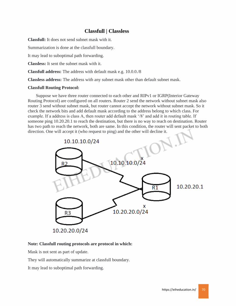
https://eiheducation.in/ 70
Classfull | Classless
Classfull: It does not send subnet mask with it.
Summarization is done at the classfull boundary.
It may lead to suboptimal path forwarding.
Classless: It sent the subnet mask with it.
Classfull address: The address with default mask e.g. 10.0.0./8
Classless address: The address with any subnet mask other than default subnet mask.
Classfull Routing Protocol:
Suppose we have three router connected to each other and RIPv1 or IGRP(Interior Gateway
Routing Protocol) are configured on all routers. Router 2 send the network without subnet mask also
router 3 send without subnet mask, but router cannot accept the network without subnet mask. So it
check the network bits and add default mask according to the address belong to which class. For
example. If a address is class A, then router add default mask ‘/8’ and add it in routing table. If
someone ping 10.20.20.1 to reach the destination, but there is no way to reach on destination. Router
has two path to reach the network, both are same. In this condition, the router will sent packet to both
direction. One will accept it (who request to ping) and the other will decline it.
Note: Classfull routing protocols are protocol in which:
Mask is not sent as part of update.
They will automatically summarize at classfull boundary.
It may lead to suboptimal path forwarding.

https://eiheducation.in/ 71
Metrics and Poisoning
Routing metric
If a router learns about multiple different paths to the same network from the same routing
protocol, a measure called metric is used to decide which route will be placed in the routing table.
Just like with the administrative distance, the lower number represents the better route.
Each routing protocol has its own way to calculate the metric; Routing Information Protocol (RIP)
uses hop counts, OPSF uses a parameter called cost, EIGRP uses bandwidth and delay to compute
the metrics, etc. Note that metrics of different routing protocols can not be directly compared – an
EIGRP route might have a metric of 4.042.334, while a RIP route can have a metric of 3.
If two routes have the same AD as well as the same metrics, the routing protocol will load-balance to
the remote network, meaning that data will be sent down each link.
This is the another method used by the distance vector routing protocols to prevent routing loops
called as route poisoning. Ehen a router defects that one of its directly connected routes has failed, it
will advertise a failed route with an infinite metric (“poisoning the route”). Routers who receive the
routing update will consider the route as failed and remove it from their routing tables.
Each routing protocol has its own definition of an infinite metric. In the case of RIP the infinite
metric is 1.
Example: We have a network of two routers. Both routers are running RIP, R2 has advertised the
10.0.0.0/24 network to R1. Now consider what happens when the network 10.0.0.0/24 fails:
1. R2 removes the route to 10.0.0.0/24 from its routing table.
2. R2 advertises the 10.0.0.0/24 network with an infinitive metric (16) to R1 (“route
poisoning”).
3. R1 receives the update and knows that the network has failed. It will remove the route from
its routing table.

https://eiheducation.in/ 72
RTP and DUAL
Reliable Transport Protocol
The Reliable Transport Protocol (RTP) manages the delivery and reception of EIGRP packets.
Reliable delivery means that delivery is guaranteed and that packets will be delivered in order.
Guaranteed delivery is accomplished by means of a Cisco – proprietary algorithm known as reliable
multicast, using the reserved class D address 224.0.0.10. Each neighbor that is receiving a reliable
multicast packet, will unicast an acknowledgment.
Ordered delivery is ensured by including two sequence number in the packet. Each packet includes a
sequence number assigned by the sending router. This sequence number is incremented by one each
time the router sends a new packet. In addition, the sending router places in the packet the sequence
number of the last packet received from the destination route.
In some cases, RTP may be unreliable delivery. No acknowledgement is required, and no sequence
number will be included for unreliably delivery EIGRP packets.
DUAL finite state machine
DUAL, the Diffusing Update Algorithm, is the algorithm used by Cisco’s EIGRP routing
protocol to ensure that a given route is recalculated globally whenever it might cause a routing loop.
According to Cisco, the full name of the algorithm is DUAL finite-state machine (DUAL FSM).
EIGRP is responsible for the routing within an autonomous system and DUAL responds to changes
in the routing topology and dynamically adjusts the routing tables of the router automatically.
EIGRP uses a feasibility condition to ensure that only loop-free routes are ever selected. The
feasibility condition is all routes to a destination although some are loop-free.
When no feasible route to a destination is available, the DUAL algorithm invokes a Diffusing
Computation to ensure that all traces of the problematic route are eliminated from the network.
https://eiheducation.in/ 73
ROUTING PROTOCOLS
RIP
Routing Information Protocol is a distance-vector, Interior Gateway Protocol (IGP) which is
used by routers to exchange routing information. RIP prevents routing loops by implementing a limit
on the number of hops. RIP uses hop count to determine the best path between two locations. Hop
count is the number of router the packet must go through till it reaches the destination network, the
maximum number of hop count of 15 by default, which means a hop count of 16 is considered an
infinite distance and the route is considered unreachable. RIP works well in small networks, but it’s
inefficient on large networks with slow WAN links or on networks with a large number of routers
installed. RIP uses the User Datagram Protocol (UDP) as its transport protocol, and is assigned the
reserved port number 520.
RIP Timers:
Update timer:
It is an interval of 30 seconds between two routing update. Each RIP enable router sends its
complete routing table to all neighboring routers every 30 seconds. This method is called as periodic
update method.
Invalid/Hold timer:
Invalid time define how much long a router should wait for an update from the neighboring
router. It is usually 180 seconds. If a router does not receives any update from a specific neighbor for
180 second then the router is declared as dead and all routes from that router are declared as invalid.
Invalid times does not remove any entry from routing table by marking it as invalid for specific
period for time.
Flush timer:
Flush timer is the time between a route becoming invalid and its removal from the routing table,
which is 240 seconds.
Versions:
There are of the Routing Information Protocol: RIPv1, RIPv2, RIPng.
RIP version 1:
RIPv1 do not carry subnet information, lacking support for variable length subnet masks
(VLSM). This limitation makes it impossible to have different-sized subnets inside the same network
class. All subnet in a network class must have the same size. There is also no support for router
authentication, making RIP vulnerable to various attacks.
RIP version 2:
Due to the deficiencies of the original RIP specification, RIP version 2 was developed. It include
the ability to carry subnet information, thus supporting Classless Inter-Domain Routing (CIDR).
RIPv2 multicast the entire routing table to all adjacent routers at the address 224.0.0.9, as opposed to
RIPv1 which uses broadcast. Unicast addressing is still allowed for special applications. Router tags
were also added in RIP version 2.
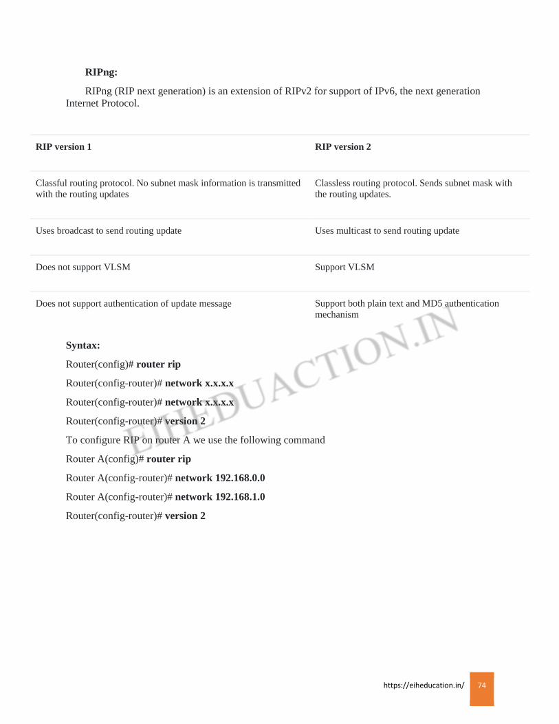
https://eiheducation.in/ 74
RIPng:
RIPng (RIP next generation) is an extension of RIPv2 for support of IPv6, the next generation
Internet Protocol.
RIP version 1 RIP version 2
Classful routing protocol. No subnet mask information is transmitted
with the routing updates
Classless routing protocol. Sends subnet mask with
the routing updates.
Uses broadcast to send routing update Uses multicast to send routing update
Does not support VLSM Support VLSM
Does not support authentication of update message Support both plain text and MD5 authentication
mechanism
Syntax:
Router(config)# router rip
Router(config-router)# network x.x.x.x
Router(config-router)# network x.x.x.x
Router(config-router)# version 2
To configure RIP on router A we use the following command
Router A(config)# router rip
Router A(config-router)# network 192.168.0.0
Router A(config-router)# network 192.168.1.0
Router(config-router)# version 2
https://eiheducation.in/ 75
IGRP
Interior Gateway Routing Protocol (IGRP):
IGRP is a distance vector Interior Gateway Protocol (IGP) developed by Cisco. It is used by
routers to exchange routing data within an autonomous system. IGRP is a proprietary protocol. IGRP
was create in order to overcome the limitation of RIP (maximum hop count of only 15, and a single
routing metric) when used within large networks. IGRP supports multiple metrics for each router,
including bandwidth, delay, load, and reliability to compare two routes there metrics are combined
together into a single metric, using a formula which can be adjusted through the use of pre-set
constants. By default, the IGRP composite metric is a sum of the segment delays and the lowest
segment bandwidth. The maximum configuration hop count of IGRP routed packets is 255 (default
100), and routing updates are broadcast every 90 second by default. IGRP uses protocol number 9 for
communication. IGRP is considered a classful routing protocol. Classful protocols have become less
popular as they are wasteful of IP address space.
Autonomous System:
An autonomous system (AS) is a network or a collection of networks that are all managed and
supervised by a single entity or organization. An AS is also sometimes referred to as a routing
domain. An AS is assigned a globally unique number, sometimes called an Autonomous System
Number (ASN). Autonomous System Number range from 1 to 65,535.
IGRP timers
Update timer: it specifies the interval between routing update message. The default is 90 seconds.
Invalid timers: it specifies how long a router should wait before declaring a route invalid if it
doesn’t receive a specific update about it. The default is three times the update period i.e. 270
seconds.
Hold-down timers:
the default is three times the update timer period plus 10 seconds i.e. 280 seconds.
Flush timer:
there indicate how much time should pass before a route should be flushed from the routing
table. The default is seven times the routing update period. If the update timer is 90 seconds by
default the 7 x 90 = 630 seconds.
Syntax:
Router(config)# router IGRP <autonomous system no.>
Router(config-router)# network x.x.x.x
Router(config-router)# network x.x.x.x
Configure for the IGRP on Router A is:
Router(config)# router IGRP 10
Router(config-router)# network 192.168.0.0
Router(config-router)# network 192.168.1.0

https://eiheducation.in/ 76
EIGRP
EIGRP
Enhance Interior Gateway Routing Protocol (EIGRP) is an advance distance-vector routing
protocol that is used on a computer network to help automate routing decisions and configuration.
The protocol was designed by Cisco systems as a proprietary protocol, available only on Cisco
routers. EIGRP is used on a router to share routes with other routers within the same autonomous
system. Unlike other well known routing protocols, such as RIP, EIGRP only send incremental
updates, reducing the workload on the router and the amount of data that needs to be transmitted.
Routers running EIGRP must become neighbors before exchanging routing information. To
dynamically discover neighbors, EIGRP routers use the multicast address of 224.0.0.10. Each EIGRP
router stores routing and topology information in three table.
Neighbor table – stores information about EIGRP neighbors
Topology table – store routing information learned from neighboring routers
Routing table – stores the best routes
EIGRP neighbors:
EIGRP must establish neighbor relationship with other EIGRP neighboring routers before
exchanging routing information. To establish neighbor relationships, routers send hello packets every
couple of seconds. Hello packets are sent to the multicast address of 224.0.0.10.
The following fields in a hello packets must be the identical in order for routers to become neighbors:
• ASN (autonomous system number)
• Subnet number
• K values (component of metric)
Feasible and reported distance:
Feasible distance (FD) is the metric of the best route to reach a network. That route will be listed
in the routing table. Reported distance (RD) is the metric advertised by a neighboring router for a
specific route. In other words, it is the metric of the route used by the neighboring router to reach the
network.
Successor and feasible successor:
A successor is the route with the best metric to reach a destination. The route is stored in the
routing table. A feasible successor is a backup path to reach that same destination that can be used
immediately if the successor route fails. These backup routes are stored in the topology table.
EIGRP topology table:
EIGRO topology table contains all learned routes to a destination, the table holds all routes
received from a neighbor, successors and feasible successors for every route, and interface on which
updates were received. The table also holds all locally connected subnets included in an EIGRP
process.
EIGRP divided into two routes
https://eiheducation.in/ 77
Internal EIGRP route:
These routes are developed within a specific autonomous system by EIGRP routes that are
members of the same autonomous system. The AD of an internal EIGRP is 90.
External EIGRP route:
These routes are developed within EIGRP routing tables by manual or automatic redistribution,
and they represent networks that are originated outside of the EIGRP autonomous system. It has an
AD of 170.
EIGRP composite and vector metrics
Bandwidth: Minimum bandwidth is in kilobits per second along the path from router to destination
network.
Load:
Number in range 1 to 255; 255 being saturated
Total delay: Delay, in 10s of microseconds, along the path from router to destination network.
Reliability:
Number in range 1 to 255; 255 being the most reliable
MTU:
Minimum path Maximum Transmission Unit is never used in the metric calculation
Hop count:
Number of routers a packet passes through when routing to a remote network, used to limit the
EIGRP AS. EIGRP maintains a hop count for ever route; however, the hop count is not used in
metric calculation, by default it is set to 100 and can be changed to any value between 1 and 255.
Syntax:
Router(config)# router eigrp 1
Router(config-router)# network x.x.x.x
Router(config-router)# network x.x.x.x
Configuration of eigrp on router A is
Router(config)# router eigrp 1
Router(config-router)# network 10.0.0.0
Router(config-router)# network 172.16.0.0
https://eiheducation.in/ 78
OSPF
OSPF
The Open Shortest Path First (OSPF) version 2 protocols were defined in RFC 2328 as an
Interior Gateway Protocol for routing information within a single Autonomous System. OSPF
protocol was developed in order to solve the problem of large scale routing and to introduce a high
functionality nonproprietary Interior Gateway Protocol for the TCP/IP protocol family. The OSPF
protocol is a linkstate routing protocol removed the Bellman-Ford vector based algorithms used in
traditional Internet routing protocols such as RIP. OSPF has introduced new concepts such as
authentication of routing update, VLSM, route summarization, etc.
OSPF Metric:
In OSPF metric is called as Cost. The cost is calculated, cost of interface is inversely
proportional to the bandwidth of that interface. A higher bandwidth indicates a lower cost.
Formula for cost
Cost= 100000000/bandwidth in bps.
OSPF network topologies:
OSPF has network categories based on architecture topology. In each topology OSPF has
different behavior. So before understanding how OSPF works in different topology we will know
what the different types of topology are:
Broadcast Multi-access network
Point-to-point
Point-to-Multipoint
Non-broadcast multi access (NBMA)
Configuration OSPF
First you need to enable OSPF on a router. This is done by using the following global
configuration command.
Router(config)# router ospf <process ID>
Process ID value is a value ranging from 1-65,535
You need to define on which interface OSPF will run and what networks will be advertised. This is
done by using the following command from the ospf configuration mode.
Router(config)# network IP_address wildcast_mask area_id
the OSPF process number doesn’t have to be the same on all routers in order to establish a neighbor
relationship, but the area id has to be the same on all neighboring routers in order for routers to
become neighbors.
First we need to enable OSPF on all routers. Then we need to define what network will be advertised
into OSPF. This can be done by the following command.
Router(config)# router ospf 1
https://eiheducation.in/ 79
Router(config-router)# network IP_address wildcast_mask area_id
Router(config-router)# network IP_address wildcast_mask area_id
Example
Router(config)# router ospf 1
Router(config-router)# network 10.0.1.0 0.0.0.255 area 0
Router(config-router)# network 172.16.0.0 0.0.255.255 area 0
Wildcard masks: A wildcard mask is a mask of bits that indicates which part of an IP address are
available for examination.
How to find wildcard masks.
We have to divide subnet mask with 255
Example
255.255.255.252
Divide every octet with 255.
255/255.255/255.255/255.252/255 = 0.0.0.3
Example 2
255.255.255.48
255/255.255/255.255/255.248/255 = 0.0.0.7
Example 3
255.0.0.0
255/255.0/255.0/255/0.255 = 0.255.255.255
Example 4
255.255.0.0
255/255.255/255.0/255.0/255 = 0.0.255.255
Designated and Backup Designated Router
Designated Router:
A Designated Router (DR) is the router interface elected among all routers on a particular multi
access network segment. Generally assumed to be broadcast multi access. Special techniques, often
vendor-dependent, may be needed to support the DR function on non-broadcast multi access
(NBMA) media. It is usually wise to configure the individual virtual circuits of NBMA subnet as
individual point-to-point lines; the techniques used are implementation dependent.
Backup Designated Router:
A Backup Designated Router (BDR) is a router that becomes the designated router if the current
designated router ha a problem or fails. The BDR is the OSPD router with second highest priority at
the time of the last election.

https://eiheducation.in/ 80
A given router can have some interface that are designated (DR) and others that are backup
designated (BDR), and others that are non-designated. If no router is a DR or a BDR on a given
subnet, the BDR is first elected, and then a second election is held for the DR.
Based on the network type, OSPF router can elect one router to be a DR and one router to be a BDR.
DR and BDR serve as the central point for exchanging OSPF routing information. Each non-DR or
non-BDR router will exchange routing information only with the DR and BDR, instead of
exchanging updates with every router on the network segment. DR will then distribute topology
information to every other router inside the same area. This greatly reduces OSPF traffic.
To send routing information to a DR or BDR he multicast address of 224.0.0.6 is used. DR sends
routing updates to the multicast address of 224.0.0.5. if DR fails, BDR takes over its role of
distributing routing information.
Every router on a network segment establishes a full neighbor relationship with the DR and BDR.
Non-DR and non-BDR routers establish a two way neighbor relationship between themselves.
On point-to-point links a DR and BDR are not elected since only two routers are directly connected.
On LANs, DR and BDR have to be elected. Two rules are used to elect a DR and BDR:
• Router with the highest OSF priority will become a DR. by default, all routers have a priority
of 1.
• If there is a tie, a router with the highest router ID wins the election.
The router with the second highest OSPF priority or router ID will become a BDR.
The Link-state advertisement (LSA) are used by routers running OSPF to exchange topology
information. An LSA contains routing and topology information that describe a part of an OSPF
network. Routers exchange LSAs and learn the complete topology of the network until all routers
have the exact same topology database.
When two neighbors decide to exchange routers, they send each other a list of LSAs in their
respective topology database. Each router then checks its topology database and sends a Link State
Request (LSR) requesting all LSAs not found in its topology table. The other router responds with
the Link State Update (LSU) that contains all LSAs requested by the neighbor.
Types of LSA
There are several different LSA types in OSPF;
Type 1 LSA:
also known as router link advertisement (RLA), a type 1 LSA is sent by every router to other
routers in its area. It contains the router, interfaces, IP information, and current interface state. Note
that Type 1 LSAs are flooded only across their own area.
Type 2 LSA:
also known as network link advertisement (NLA), a Type @ LSA is generated by designated
routers to send out information about the state of other routers that are part of the same network.
Type 2 LSAs are flooded across their own area only.
https://eiheducation.in/ 81
Type 3 LSA:
also known as summary link advertisement (SLA), a Type 3 LSA is generated by area border
router (ABR) and sent toward the area external to the one where they were generated. It contains the
IP information and RID of the ABR that is advertising an LSA type 3.
Type 4 LSA:
informs the rest of the OSPF domain how to get to the ASBR. The link-state ID includes the
router ID of the described ASBR.
Type 5 LSA:
also known as external link advertisement, a type 5 LSA is sent by autonomous system boundary
router (ASBRs) to advertise routers that are external to the OSPF autonomous system and are flooded
everywhere.
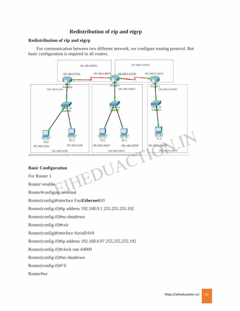
https://eiheducation.in/ 82
Redistribution of rip and eigrp
Redistribution of rip and eigrp
For communication between two different network, we configure routing protocol. But
basic configuration is required in all routers.
Basic Configuration
For Router 1
Router>enable
Router#configure terminal
Router(config)#interface FastEthernet0/0
Router(config-if)#ip address 192.168.0.1 255.255.255.192
Router(config-if)#no shutdown
Router(config-if)#exit
Router(config)#interface Serial0/0/0
Router(config-if)#ip address 192.168.0.97 255.255.255.192
Router(config-if)#clock rate 64000
Router(config-if)#no shutdown
Router(config-if)#^Z
Router#wr

https://eiheducation.in/ 83
For Router 2
Router>enable
Router#configure terminal
Router(config)#interface FastEthernet0/0
Router(config-if)#ip address 192.168.0.65 255.255.255.224
Router(config-if)#no shutdown
Router(config-if)#exit
Router(config)#interface Serial0/1/0
Router(config-if)#ip address 192.168.0.98 255.255.255.252
Router(config-if)#no shutdown
Router(config-if)#exit
Router(config)#interface Serial0/0/0
Router(config-if)#ip address 192.168.0.101 255.255.255.252
Router(config-if)#clock rate 64000
Router(config-if)#no shutdown
Router(config-if)#^Z
Router#wr
For Router 3
Router>enable
Router#configure terminal
Router(config)#interface FastEthernet0/0
Router(config-if)#ip address 192.168.0.105 255.255.255.252
Router(config-if)#no shutdown
Router(config-if)#exit
Router(config)#interface Serial0/1/0
Router(config-if)#ip address 192.168.0.102 255.255.255.252
Router(config-if)#no shutdown
Router(config-if)#^Z
Router#wr
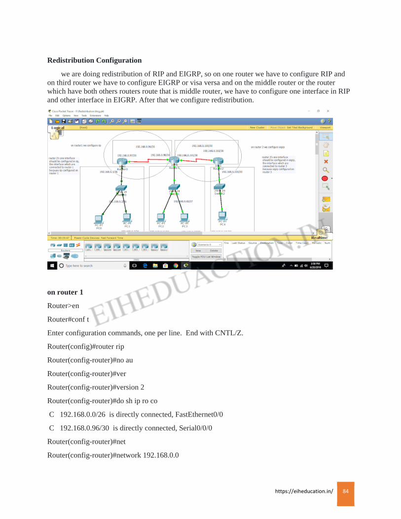
https://eiheducation.in/ 84
Redistribution Configuration
we are doing redistribution of RIP and EIGRP, so on one router we have to configure RIP and
on third router we have to configure EIGRP or visa versa and on the middle router or the router
which have both others routers route that is middle router, we have to configure one interface in RIP
and other interface in EIGRP. After that we configure redistribution.
on router 1
Router>en
Router#conf t
Enter configuration commands, one per line. End with CNTL/Z.
Router(config)#router rip
Router(config-router)#no au
Router(config-router)#ver
Router(config-router)#version 2
Router(config-router)#do sh ip ro co
C 192.168.0.0/26 is directly connected, FastEthernet0/0
C 192.168.0.96/30 is directly connected, Serial0/0/0
Router(config-router)#net
Router(config-router)#network 192.168.0.0
https://eiheducation.in/ 85
Router(config-router)#network 192.168.0.96
Router(config-router)#^Z
Router#
%SYS-5-CONFIG_I: Configured from console by console
Router#wr
Building configuration…
[OK]
On router 3
Router>en
Router#sh ip ro co
C 192.168.0.100/30 is directly connected, Serial0/1/0
C 192.168.0.104/30 is directly connected, FastEthernet0/0
Router#conf t
Enter configuration commands, one per line. End with CNTL/Z.
Router(config)#router eigrp 10
Router(config-router)#no au
Router(config-router)#network 192.168.0.100
Router(config-router)#
%DUAL-5-NBRCHANGE: IP-EIGRP 10: Neighbor 192.168.0.101 (Serial0/1/0) is up: new
adjacency
Router(config-router)#network 192.168.0.104
Router(config-router)#^Z
Router#
%SYS-5-CONFIG_I: Configured from console by console
Router#wr
Building configuration…
[OK]
On router 2
Router>en
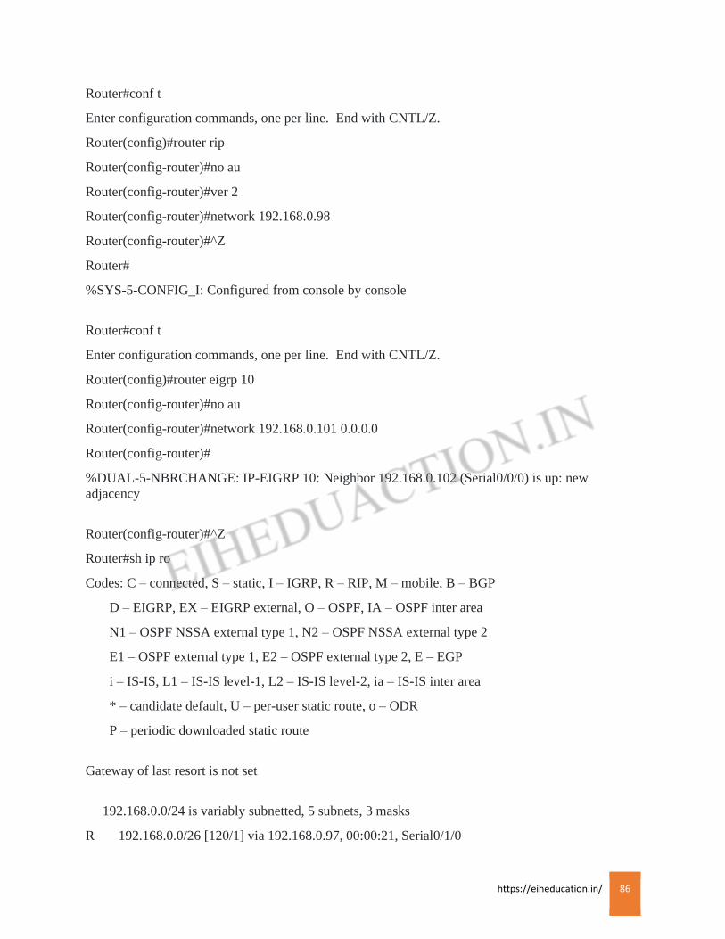
https://eiheducation.in/ 86
Router#conf t
Enter configuration commands, one per line. End with CNTL/Z.
Router(config)#router rip
Router(config-router)#no au
Router(config-router)#ver 2
Router(config-router)#network 192.168.0.98
Router(config-router)#^Z
Router#
%SYS-5-CONFIG_I: Configured from console by console
Router#conf t
Enter configuration commands, one per line. End with CNTL/Z.
Router(config)#router eigrp 10
Router(config-router)#no au
Router(config-router)#network 192.168.0.101 0.0.0.0
Router(config-router)#
%DUAL-5-NBRCHANGE: IP-EIGRP 10: Neighbor 192.168.0.102 (Serial0/0/0) is up: new
adjacency
Router(config-router)#^Z
Router#sh ip ro
Codes: C – connected, S – static, I – IGRP, R – RIP, M – mobile, B – BGP
D – EIGRP, EX – EIGRP external, O – OSPF, IA – OSPF inter area
N1 – OSPF NSSA external type 1, N2 – OSPF NSSA external type 2
E1 – OSPF external type 1, E2 – OSPF external type 2, E – EGP
i – IS-IS, L1 – IS-IS level-1, L2 – IS-IS level-2, ia – IS-IS inter area
* – candidate default, U – per-user static route, o – ODR
P – periodic downloaded static route
Gateway of last resort is not set
192.168.0.0/24 is variably subnetted, 5 subnets, 3 masks
R 192.168.0.0/26 [120/1] via 192.168.0.97, 00:00:21, Serial0/1/0
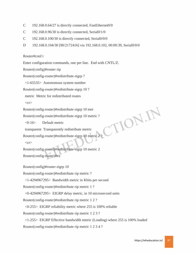
https://eiheducation.in/ 87
C 192.168.0.64/27 is directly connected, FastEthernet0/0
C 192.168.0.96/30 is directly connected, Serial0/1/0
C 192.168.0.100/30 is directly connected, Serial0/0/0
D 192.168.0.104/30 [90/2172416] via 192.168.0.102, 00:00:39, Serial0/0/0
Router#conf t
Enter configuration commands, one per line. End with CNTL/Z.
Router(config)#router rip
Router(config-router)#redistribute eigrp ?
<1-65535> Autonomous system number
Router(config-router)#redistribute eigrp 10 ?
metric Metric for redistributed routes
<cr>
Router(config-router)#redistribute eigrp 10 met
Router(config-router)#redistribute eigrp 10 metric ?
<0-16> Default metric
transparent Transparently redistribute metric
Router(config-router)#redistribute eigrp 10 metric 2 ?
<cr>
Router(config-router)#redistribute eigrp 10 metric 2
Router(config-router)#ex
Router(config)#router eigrp 10
Router(config-router)#redistribute rip metric ?
<1-4294967295> Bandwidth metric in Kbits per second
Router(config-router)#redistribute rip metric 1 ?
<0-4294967295> EIGRP delay metric, in 10 microsecond units
Router(config-router)#redistribute rip metric 1 2 ?
<0-255> EIGRP reliability metric where 255 is 100% reliable
Router(config-router)#redistribute rip metric 1 2 3 ?
<1-255> EIGRP Effective bandwidth metric (Loading) where 255 is 100% loaded
Router(config-router)#redistribute rip metric 1 2 3 4 ?

https://eiheducation.in/ 88
<1-65535> EIGRP MTU of the path
Router(config-router)#redistribute rip metric 1 2 3 4 5 ?
<cr>
Router(config-router)#redistribute rip metric 1 2 3 4 5
Router(config-router)#^Z
Router#
%SYS-5-CONFIG_I: Configured from console by console
Router#wr
Building configuration…
[OK]
Router 1 has rip route and router 3 has eigrp route, router 2 have both rip and eigrp route
after configure interface of router 2 in respective protocol.
After configuration of redistribution, apply verification command in router 3.
Router#sh ip ro
Codes: C – connected, S – static, I – IGRP, R – RIP, M – mobile, B – BGP
D – EIGRP, EX – EIGRP external, O – OSPF, IA – OSPF inter area
N1 – OSPF NSSA external type 1, N2 – OSPF NSSA external type 2
E1 – OSPF external type 1, E2 – OSPF external type 2, E – EGP
i – IS-IS, L1 – IS-IS level-1, L2 – IS-IS level-2, ia – IS-IS inter area
* – candidate default, U – per-user static route, o – ODR
P – periodic downloaded static route
Gateway of last resort is not set
192.168.0.0/24 is variably subnetted, 5 subnets, 3 masks
D EX 192.168.0.0/26 [170/2560512512] via 192.168.0.101, 00:00:16, Serial0/1/0
D EX 192.168.0.64/27 [170/2560512512] via 192.168.0.101, 00:00:16, Serial0/1/0
D EX 192.168.0.96/30 [170/2560512512] via 192.168.0.101, 00:00:16, Serial0/1/0
C 192.168.0.100/30 is directly connected, Serial0/1/0
C 192.168.0.104/30 is directly connected, FastEthernet0/0
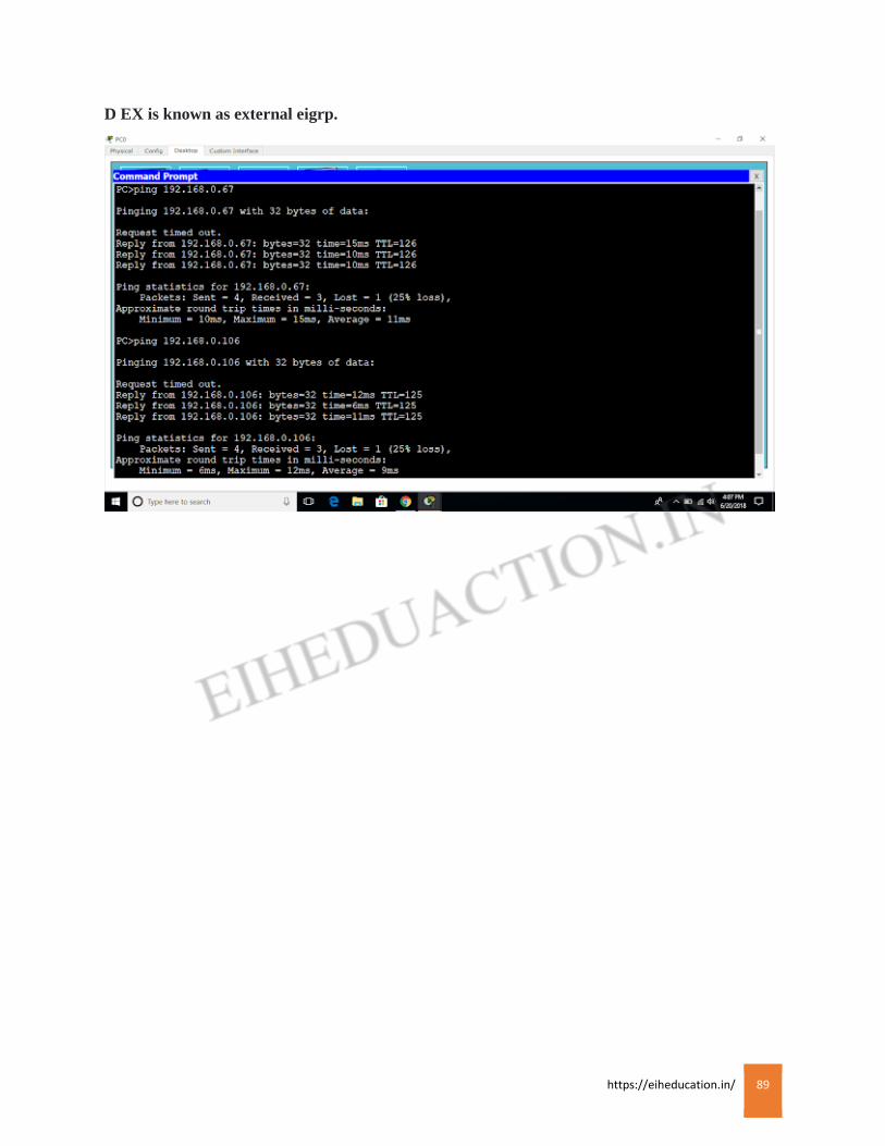
https://eiheducation.in/ 89
D EX is known as external eigrp.

https://eiheducation.in/ 90
DHCP
DHCP
Dynamic Host Configuration Protocol (DHCP) is a protocol that was invented to address
some problems like, in our network, all end user devices need an IP address to access the network.
Static IP addresses are usually assigned to routers, management interfaces on switches, servers and
other devices in the network which do no t change location either physically or logically. Static IP
address are also used to access and manage these devices remotely. On the other hand, user devices
such as computers, smart phones, IP phones and others are like to change their location either
physically or logically. This means that assigning them static IP address would be an unavailable
solution.
DHCP port number is 67. With DHCP, we can assign IP address information to user nodes
automatically which saves on the administrative overhead that would be involved in assigning IP
addressing information to clients statically.
DHCP Operation:
Assigning IP addressing information to user devices is one of the most important tasks that are
performed by the DHCP servers in our networks. It accomplishes these tasks in one of three ways:
Manual IP allocation:
In this type of DHCP allocation, the network administrator assigns users with IP addresses from
the DHCP server and then the DHCP server communicates this information to the clients.
Automatic IP allocation:
In this mode, the DHCP server assigns static IP addresses to clients from a pool. These addresses
do not change unless the administrator configure it differently.
Dynamic IP allocation:
In this mode, the administrator configure a pool of addresses which can be assigned to clients.
The clients then request the IP addressing information for a particular time period, when the time
expires, the IP address is returned to the DHCP pool and the client has to request another IP address.
When a PC is connected to a DHCP server, the DHCP server usually gives it IP addressing
information. The PC can use the IP addressing information it has been assigned until the specified
lease period expires.
Excluding Address:
Exclude IP addresses configured on the router’s interfaces, switch management interface and
server from DHCP. The devices we will exclude from participation in DHCP have been configured
with static IP addresses. It is highly unlikely that theses devices will be moved any time soon and
also statically configured IP addresses on these devices helps in troubleshooting when there is a
problem.
Syntax:
R1(config)#ip dhcp excluded-address <start_ip_address> <end_ip_address>
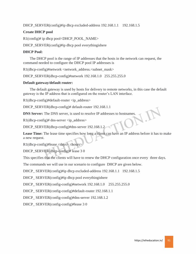
https://eiheducation.in/ 91
DHCP_SERVER(config)#ip dhcp excluded-address 192.168.1.1 192.168.1.5
Create DHCP pool
R1(config)# ip dhcp pool<DHCP_POOL_NAME>
DHCP_SERVER(config)#ip dhcp pool everythingishere
DHCP Pool:
The DHCP pool is the range of IP addresses that the hosts in the network can request, the
command needed to configure the DHCP pool IP addresses is
R1(dhcp-config)#network <network_address.<subnet_mask>
DHCP_SERVER(dhcp-config)#network 192.168.1.0 255.255.255.0
Default gateway/default router:
The default gateway is used by hosts for delivery to remote networks, in this case the default
gateway is the IP address that is configured on the router’s LAN interface.
R1(dhcp-config)#default-router <ip_address>
DHCP_SERVER(dhcp-config)# default-router 192.168.1.1
DNS Server: The DNS server, is used to resolve IP addresses to hostnames.
R1(dhcp-config)# dns-server <ip_address>
DHCP_SERVER(dhcp-config)#dns-server 192.168.1.2
Lease Time: The lease time specifies how long a client can have an IP address before it has to make
a new request.
R1(dhcp-config)#lease <days> <hours>
DHCP_SERVER(dhcp-config)# lease 3 0
This specifies that the clients will have to renew the DHCP configuration once every three days.
The commands we will use in our scenario to configure DHCP are given below.
DHCP_ SERVER(config)#ip dhcp excluded-address 192.168.1.1 192.168.1.5
DHCP_ SERVER(config)#ip dhcp pool everythingishere
DHCP_ SERVER(config-config)#network 192.168.1.0 255.255.255.0
DHCP_ SERVER(config-config)#default-router 192.168.1.1
DHCP_ SERVER(config-config)#dns-server 192.168.1.2
DHCP_ SERVER(config-config)#lease 3 0

https://eiheducation.in/ 92
DHCP Relay:
The DHCP server will most likely not be the router and it will be located on a server farm. This
may be a problem for clients who want to get IP addresses.
An IP helper address is a solution that enables routers in the network to forward DHCP broadcast
messages from the local network to a DHCP server that may be in a different network. In this
situation, the router usually relays request to the DHCP server which then can communicate IP
addressing information to the user devices.
Syntax:
R1(config)#interface <interface_ID><interface_number>
R1(config-if)#ip helper-address <DHCP_SERVER_IP_ADDRESS>
https://eiheducation.in/ 93
NTP
NTP
Network Time Protocol:
NTP is a protocol that synchronizes clocks of your network devices.
Correct network time within the network is important;
Connect time allows the tracking of events in the network in the correct order.
Clock synchronization is critical for the correct interpretation of events within the syslog data.
Clock synchronization is critical for digital certificates.
To make sure all devices are synchronized with the same time information, we’ll configure our
devices to receive the accurate time information from a centralized server.
NTP Configuration:
R1(config)#ntp server <NTP_SERVER_IP_ADDRESS>
R1(config)#ntp server 192.168.1.2
R1# show clock (before and after configuration NTP)
R1#show clock
to verify that we are receiving the correct time we use command “show ntp status”
R1#show ntp status.
https://eiheducation.in/ 94
Backup and Restore Backup and Restore Boot system command: –
This command should be use when configuration register value is set to it’s default value i.e. 2102
1) #conf t
#boot system flash <ios file name>
2) #conf t
#boot system tftp
While booting up router will reach tftp server and it will load IOS file from the tftp server
Command to take backup of your IOS file in TFTP server
#copy flash TFTP
Before you back up your IOS image to an external server, you should perform the following checks:
* Is the server reachable
* Is there enough disk space on the server to hold the IOS image
* Does server support the file nomenclature that you want to use
* Does file have to exist on the server before you can perform the copy?
Command to Load IOS file from TFTP server in to FLASH memory
#copy TFTP flash
Another way to take a backup:
1. Install TFTP server application.
2. To remove all information = #write erase
3. To restart the router = #reload
4. Configure the router (assign the IP address compulsory: without IP address backup is not
possible.)
5. Router#copy startup-config :tftp
6. Address or remote host name: (IP address) e.g. 10.0.0.2
7. Destination file name: (Name) e.g. backuprouter
8. Router# write erase
9. #reload
10. First assign FastEthernet IP address in router
11. Router#copy tftp: startup-config
12. Address or name of remote host: 10.0.0.2
13. Destination filename
[startup-config]
(press enter)
1. #copy startup-config running-config
2. Destination filename
[running-config]
(press enter)
https://eiheducation.in/ 95
Set Password and Recovery How to set password for user mode.
enable
conf t
line console 0
password eihtech
login
how to set password for privallege mode.
enable
conf t
enable password eih1234
how to enable secret password
enable
conf t
enable secret password tech12
how to set telnet password
line vty 0 4
password ccnp
login
PASSWORD RECOVERY
* Connect console cable to com1 port of pc and another end of rollover cable to console port of
router
* Before switching on router open hyper terminal application , switch on your router press
control+break(pause) for going in to ROMMON mode
* Change configuration register number to 2142 by using command
[rommon1>confreg 2142]
Now reset router by
rommon1>reset command or boot router by,
rommon1>boot
Now router will prompt you to enter in to initial configuration mode. Type “no” there.
* Now load your startup-configuration in to Running
Router# copy startup-config running-config
Now change VTY and enable password, and check whether your interfaces are “up” at layer1 by
#show interface brief
https://eiheducation.in/ 96
If interfaces are not “up”, then make them “up” at physical layer by “no shutdown” command
Now copy Running-configuration in to startup configuration
#copy running-config startup-config
Change configuration register to “2102”
#configure terminal
#config-register 2102
Now you should be able to ACCESS the router via VTY
https://eiheducation.in/ 97
ACL ACL
An ACL (Access List) is a list of statements that are meant to either permit or deny the
movement of data from the network layer and above. They are used to filter traffic in our networks as
required by the security policy.
Packet filtering :
Filtering of packets, is a way to check the incoming packets and outgoing packets against set
criteria so as to determine whether they should be forwarded or dropped. This is usually
accomplished by a router. The traffic can be filter based on destination and source layer 3 address.
Destination and source port number, as well as the protocol in use.
The three rules of configuration ACLs:
There are three rules that should always be observed when configuration ACLs. These rules
determine how traffic on a network will flow and therefore they should not be ignored.
ACL per protocol:
This is to control each of the protocols that you have configured on your router.
ACL per direction:
There are two directions in this case; inbound traffic is the traffic is coming into the router while
outbound traffic is the traffic that is leaving the router.
ACL per interface:
This is meant to control traffic from leaving through a specified interface.
Types of ACLs:
Numbered and Named Access Lists:
A Numbered Access Lists is assigned a unique number among all Access List, but a Named
Access List is defined by a unique name.
Standard and Extended Access Lists:
Standard Access Lists can be used filter traffic only based on the source IP address of the IP
datagram packet. An extended Access List can be used to filter traffic based on Source IP address,
Destination IP address, Protocol (TCP,UDP,etc.) port Number etc.
Access List type and number
Standard 1-99, 1300-1999
Extended 100-199, 2000-2699
Standard Access List
Configuration commands
The full syntax of the standard ACL command is as follow:
Router(config)#access-list<ACLno><deny/permit><source_network><wildcard_mast>
https://eiheducation.in/ 98
Router(config)#access-list 1 permit 192.168.1.0 0.0.0.255
The full syntax of the standard ACL command to filter a specific host is as follow:
Router(config)#access-list<ACLno><deny/permit><source_ip_address><wildcard_mast>
Router(config)#access-list 1 permit 192.168.1.2 0.0.0.0
Or
Router(config)#access-list<ACLno><deny/permit><host><source_ip_address>
Router(config)#access-list 1 deny host 192.168.1.2
The command to permit all address is:
Router(config)#access-list<ACLno> permit 0.0.0.0 255.255.255.255
or
Router(config)#access-list<ACLno> permit any
The next command is used to apply the access lists to the appropriate interface.
Router(config)#ip access-group <ACLno> <out/in>
Router(config)#ip access-group 1 in
Inbound access list:
packet are proceed through the access list by being routed to the outbound interface.
Outbound access list:
packet are routed to the outbound interface and then proceed through the access list
Extended Access List:
it allows you to permit or deny traffic from specific IP addresses to a specific destination IP
address and port. Extended IP Access Lists are almost identical to standard IP access lists in their
use. The key difference between the two types is the variety of fields in the packet that can be
compared for matching by extended access lists. The extended Control list can filter the traffic based
on many other factors like.
Source and destination IP addresses.
Protocol like IP, TCP, UDP, ICMP etc.
Protocol information Port number for TCP and UDP or message type for ICMP.
Syntax:
Router(config)#access-list [ACLno] permit\deny IP_protocol source_address Source-
wildcard_mask [source_protocol_information] detination_address destination_wildcard_mask
[destination_protocol_information]
ACLno: For Extended Access Control List, Access list number must be between 100-199 or 2000-
2699.
Permit/deny: Whether to permit or deny traffic.
https://eiheducation.in/ 99
IP_protocol: IP protocol to match. The IP protocols can be IP, ICMP, TCP etc.
Source_address: Source IP address.
Source_wildcard_mask: Source wildcard mask.
Source_protocol_information: additional source protocol information like TCP or UDP port
numbers.
Destination_address: Destination IP address.
Destination_wildcard_mast: destination wildcard mask.
Destination_protocol_information: Additional destination protocol information like TCP or UDP
port number.
Wildcard mask:
Instead of specifying a single IP address, you can also permit or deny network/subnetwork by
using wildcard mask, also known as inverse masks.
Router(config)#access-list 100 deny tcp any host 192.168.0.22 eq 23
the line says to deny source host trying to telnet to destination host 192.168.0.2. keep in mind that the
next line is an implicit deny by default. If you apply this access list to an interface, you might as well
just shut the interface down because by default, there’s an implicit deny all the end of every access
list.
Router(config)#access-list 100 permit ip any any
The IP in this line is important because it will permit the IP stack. If TCP was used instead of IP in
this line, then UDP, etc. would all be denied.
Now we need to apply it to an interface with the same command used for the IP standard list:
Router(config)#ip access-group 100 in
Or
Router(config)#ip access-group 100 out
Named Access List: Name Access Lists are much like standard and extended access list but with
names and addition of line numbers. You can give name to identify your access lists. Named Access
Lists allows standard and extended ACLs to be given names instead of numbers. That means we can
either have a Standard Named Access List or Extended Named Access List.
Syntax for Standard Named Access List:
R1>enable
R1>configuration terminal
R1(config)#ip access-list standard BLOCK_NETWORK1
R1(config-std-nacl)#deny 172.16.0.0 0.0.255.255
R1(config-std-nacl)#permit any
R1(config-std-nacl)#exit
https://eiheducation.in/ 100
R1(config)#exit
After this you have to configure Standard Name Access List on interface with “in/out” keyword.
R3>enable
R3#conf t
R3(config)#interface fa0/0
R3(config-if)#ip access-group BLOCK_NETWORK1 out
R3(config-if)#exit
R3(config)#exit
Syntax of Extended Named Access List
R1>enable
R1#conf t
R1(config)#ip access-list extended BLOCK_WS03
R1(config-ext-nacl)#deny tcp host 172.16.0.12 host 172.20.0.5 eq 80
R1(config-ext-nacl)#permit ip any any
R1(config-ext-nal)#exit
R1(config)#exit
There is an implicit “deny any” at the end of every Access Lists. If there is no “permit ip any any”
statement at the end, above Extended Named Access Lists may filter out all traffic. The “permit ip
any any” statement permits any other IP traffic, if there is no matching deny in previous statement.
Above Extended Named Access Lists effectively allow all the traffic except the HTTP traffic from
172.16.0.12/16 to 172.20.0.5/16.
Configure interface
R1>enable
R1#conf t
R1(config)#interface fa0/0
R1(config-if)#ip access-group BLOCK_WS03 in
R1(config-if)#exit
R1(config)#exit

https://eiheducation.in/ 101
NAT
NAT
NAT (Network Address Translation) allows a network device such as a Router or firewall to
translate address between the public internet and a local private network. The main reason why NAT
(Network Address Translation) technology developed was to prevent the fast depletion op ipv4
address.
There are defined ranges of private ipv4 addresses that can be used to configure ipv4 addresses for
private use. The ipv4 traffic originating from or destined to private ipv4 address is not allowed to
move or dropped in a public internet router. This permits the re-usability of private ipv4 address in
different non-public networks.
There is no ipv4 address conflict between two private ipv4 addresses separated by NAT devices.
Because, the private ipv4 addresses are translated to globally unique public ipv4 address, when they
leave their own network.
Nat allows only a single globally unique ipv4 address to represent an entire network to outside world.
Inside local address:
these are the private ipv4 addresses that are used to address hosts in the private network.
Inside global address:
this is an IP address that can be used by a host in the internal network to access the internet.
Outside global address:
this is any public ipv4 address that has been configured on a device on the internet.
Outside local address:
this is similar to the outside global addresses and they are local ip addresses configured on any
external network.
Static
Router#conf t
Router(config)#ip nat inside source static 192.168.0.2 50.0.0.2
Router(config)#ip nat inside source static 192.168.0.3 50.0.0.3
Router(config)#int fastEthernet 0/0
Router(config-if)#ip nat inside
Router(config-if)#ex
Router(config)#int serial 0/0/0
Router(config-if)#ip nat outside
Router(config-if)#^Z
https://eiheducation.in/ 102
Dynamic
Router#conf t
Router(config)#ip nat pool ccna 60.0.0.2 60.0.0.10 netmask 255.0.0.0
Router(config)#access-list 12 permit 192.168.0.64 0.0.0.31
Router(config)#ip nat inside source list 12 pool ccna
Router(config)#int fastEthernet 0/0
Router(config-if)#ip nat inside
Router(config-if)#ex
Router(config)#int serial 0/1/0
Router(config-if)#ip nat outside
Router(config-if)#^Z
Router#wr
overload (pat)
Router#conf t
Router(config)#ip nat pool ccna 60.0.0.2 60.0.0.10 netmask 255.0.0.0
Router(config)#access-list 12 permit 192.168.0.64 0.0.0.31
Router(config)#ip nat inside source list 12 pool ccna overload
Router(config)#int fastEthernet 0/0
Router(config-if)#ip nat inside
Router(config-if)#ex
Router(config)#int serial 0/1/0
Router(config-if)#ip nat outside
Router(config-if)#^Z
Router#wr
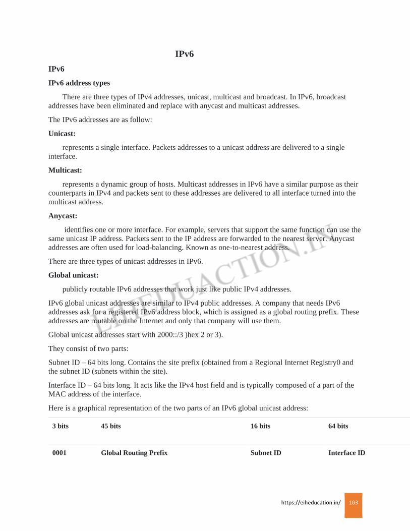
https://eiheducation.in/ 103
IPv6
IPv6
IPv6 address types
There are three types of IPv4 addresses, unicast, multicast and broadcast. In IPv6, broadcast
addresses have been eliminated and replace with anycast and multicast addresses.
The IPv6 addresses are as follow:
Unicast:
represents a single interface. Packets addresses to a unicast address are delivered to a single
interface.
Multicast:
represents a dynamic group of hosts. Multicast addresses in IPv6 have a similar purpose as their
counterparts in IPv4 and packets sent to these addresses are delivered to all interface turned into the
multicast address.
Anycast:
identifies one or more interface. For example, servers that support the same function can use the
same unicast IP address. Packets sent to the IP address are forwarded to the nearest server. Anycast
addresses are often used for load-balancing. Known as one-to-nearest address.
There are three types of unicast addresses in IPv6.
Global unicast:
publicly routable IPv6 addresses that work just like public IPv4 addresses.
IPv6 global unicast addresses are similar to IPv4 public addresses. A company that needs IPv6
addresses ask for a registered IPv6 address block, which is assigned as a global routing prefix. These
addresses are routable on the Internet and only that company will use them.
Global unicast addresses start with 2000::/3 )hex 2 or 3).
They consist of two parts:
Subnet ID – 64 bits long. Contains the site prefix (obtained from a Regional Internet Registry0 and
the subnet ID (subnets within the site).
Interface ID – 64 bits long. It acts like the IPv4 host field and is typically composed of a part of the
MAC address of the interface.
Here is a graphical representation of the two parts of an IPv6 global unicast address:
3 bits 45 bits 16 bits 64 bits
0001 Global Routing Prefix Subnet ID Interface ID
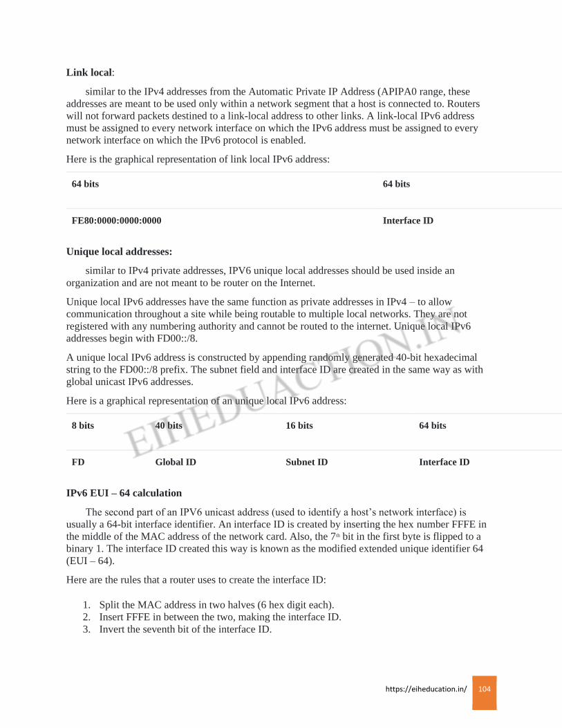
https://eiheducation.in/ 104
Link local:
similar to the IPv4 addresses from the Automatic Private IP Address (APIPA0 range, these
addresses are meant to be used only within a network segment that a host is connected to. Routers
will not forward packets destined to a link-local address to other links. A link-local IPv6 address
must be assigned to every network interface on which the IPv6 address must be assigned to every
network interface on which the IPv6 protocol is enabled.
Here is the graphical representation of link local IPv6 address:
64 bits 64 bits
FE80:0000:0000:0000 Interface ID
Unique local addresses:
similar to IPv4 private addresses, IPV6 unique local addresses should be used inside an
organization and are not meant to be router on the Internet.
Unique local IPv6 addresses have the same function as private addresses in IPv4 – to allow
communication throughout a site while being routable to multiple local networks. They are not
registered with any numbering authority and cannot be routed to the internet. Unique local IPv6
addresses begin with FD00::/8.
A unique local IPv6 address is constructed by appending randomly generated 40-bit hexadecimal
string to the FD00::/8 prefix. The subnet field and interface ID are created in the same way as with
global unicast IPv6 addresses.
Here is a graphical representation of an unique local IPv6 address:
8 bits 40 bits 16 bits 64 bits
FD Global ID Subnet ID Interface ID
IPv6 EUI – 64 calculation
The second part of an IPV6 unicast address (used to identify a host’s network interface) is
usually a 64-bit interface identifier. An interface ID is created by inserting the hex number FFFE in
the middle of the MAC address of the network card. Also, the 7th bit in the first byte is flipped to a
binary 1. The interface ID created this way is known as the modified extended unique identifier 64
(EUI – 64).
Here are the rules that a router uses to create the interface ID:
1. Split the MAC address in two halves (6 hex digit each).
2. Insert FFFE in between the two, making the interface ID.
3. Invert the seventh bit of the interface ID.
https://eiheducation.in/ 105
For example, if the MAC address of a network card is 00:BB:CC:DD:11:22, the interface ID would
be 02BBCCFFFFEDD1122.
Why is that so?
Well, the router will first flip the seventh bit from 0 to 1. MAC addresses are in hex format. The
binary format of the MAC address look like this:
Hex- 00BBCCDD1122
Binary – 0000 0000 1011 1011 1100 1100 1101 1101 0001 0001 0010 0010
The router will flip the seventh bit:
Binary – 0000 0000 1011 1011 1100 1100 1101 1101 0001 0001 0010 0010
This will result in the following hexadecimal address:
Hex – 02BBCCDD1122
Next, the router will insert FFFE in the middle of the address listed above:
Hex – 02BBCCFFFEDD1122
So, the interface ID will be 02BB:CCFF:FEDD:1122.
For interfaces that don’t have a MAC address (e.g. Serial interface), the router chooses the MAX of
the lowest-numbered interface that has a MAC.

https://eiheducation.in/ 106
SWITCH
Network Switch
Switch is a computer networking device that connects devices together on a
computer network, by using packet switching to receive and process and forward
data to the destination device. Switch forward to one or multiple devices that need
to receive it, rather than broadcasting the same data out of each of its ports. It
works on a layer-2 of OSI model which is Data-link layer.
A network switch is a multiport network bridges that used hardware address (MAC
address) to process and forward data at the data link layer of the OSI model.
Switches can also process data at the network layer by additionally incorporating
routing functionality that most commonly uses IP addresses to perform packet
forwarding: such switches are commonly known as layer-3 switches or multilayer
switches.
It is a plug and play device.
It is use for large network.
They operate in full duplex.
We can connect n-number of host.
It is a intelligent device.
It has a memory chip (ASIC).
Its broadcast only once(1st time) the unicast the message after learn mac-address.
It can learn mac-address.
Internal structure: Its work on a data link layer and data send in frame format.
One domain has multiple collision.
TYPES OF SWITCH
1) LAN switch.
2) Manageable Switch.
3) Unmanageable Switch.
LAN switch: A LAN switch is a centralized device connected to multiple PC or
nodes. each port on a switch is in a separate collision domain. It is quiet intelligent
to understand the mac-address of the PC or nodes and stores into a repository
called CAM table or mac-address-table. Every switch port is made up of special
hardware called ASIC(Application Specific Integrated Circuit.
Manageable switch: A Manageable network switch is configurable, offering
greater security, flexibility, and capacity than an unmanageable switch. You can
monitor and adjust a manageable switch locally or remotely, to give you greater
network control.
Many more features can be configured on the LAN switch that scales the
performance of a LAN with lots of layer-2 benefits (including VTP, STP, RSTP,
PVST etc.)
Unmanageable switch: It is a plug and play device. An Unmanageable switch
works right out of the box. It’s not design to be configured, So you don’t have to

https://eiheducation.in/ 107
worry about installing or setting it up correctly. Unmanageable switches have
fewer features and less network capacity than manageable switches. You’ll usually
find unmanageable switches in home networking equipment. Unmanaged switches
can be desktop or rack mounted.
https://eiheducation.in/ 108
Domains in switch
Collision Domains :
A collision domain is a the set of LAN interfaces whose frames could collide with each other ,
but not with frames set by any other devices in the network. The collision is occur when two
computers want to use bandwidth at the same time. Generally speaking in easy terms, A
collision domain is a set of PC for which a frame sent by one PC could result in a collision with a
frame sent by any other PC in the same collision domain.
Only one device in the collision domain may transmit at any one time, and the other devices in the
domain listen to the network in order to avoid data collision. Collision also decrease network
efficiency on a collision domain; if two devices transmit simultaneously, a collision occurs, and both
devices must retransmit at a later time.
Modern wired networks use a network switch to eliminate collision. By connecting each device
directly to a port on the switch, either each port on a switch become its own collision domain in case
of half duplex links or the possibility of collisions is eliminated entirely in the case of full
duplexlinks.
Broadcast Domains :
A broadcastdomain is a logical division of acomputer network, in which all nodes can reach
each other by broadcast at the data link layer. A broadcast domain can be within the same LAN
segment or it can be bridged to other LAN segment .When one of the devices sends a broadcast, all
the other devices receive a copy of the broadcast. For example, switches flood broadcasts and
multicasts on all the ports. Because broadcast frames are sent out all ports, a switch creates asingle
broadcast domain.
Any computer connected to the same switch is a member of the samebroadcast domain. Routers and
other higher-layer devices form boundaries between broadcast domains.
Collision domains are generally smaller than broadcast domains. Broadcast domains are only divided
by layer 3 network devices such as router or layer 3 switches.
https://eiheducation.in/ 109
STP
STP
Spanning-Tree Protocol (STP) is a loop-prevention protocol used in switching environment. The
basic function of STP is to prevent bridge loops and the broadcast radiation that result from them.
When a switch receives a frame and it does not find any entry for destination address in MAC table it
broadcast the packet to all ports. So when other switches receive the same packet and the too do not
find any entry in MAC table they also broadcast the packet to all available ports. Thus every witch in
the topology uses broadcast unless and until the destination is found and thus can create a loop.
In order to prevent from broadcast storm or looping problem a protocol called as STP was created by
DIX(Digital, Intel and Xerox) as a switching loop prevention protocol. Then IEEE created their own
version of STP called as 802.1d. The goal behind developing STP is to create a loop free network by
block redundant link.
How STP works
Selecting the Root Bridge
Selecting the Root Port
Selecting Designated Port and Non Designated Port
The STP algorithm is responsible for identifying active redundant links in the network and blocking
one of these links, thus preventing possible network loops.
STP enabled switches exchange BPDU messages between them to agree upon the “root bridge”, the
process is called Root Bridge Election.
Once the root bridge is elected, every switch has to determined which of its ports will communicate
with the root bridge. Therefore Root Port Election take place on every network switch.
Designated Port Election takes place in order to have only one active path towards every network
segment.
Select a root bridge
The root bridge of the spanning tree is the switch with the smallest or lowest bridge ID. Each
cisco switch has a configuration priority number and a MAC address. The bridge default priority is
32768 and can only be configured in multiples of 4096. When comparing two bridge ID, the priority
portions are compared first and the MAC address are compared only if the priorities are equal.
The switch with the lowest priority of all the switches will be the root; if there is a tie, then the switch
with the lowest priority and lowest MAC address will be the root bridge.
For example, if switch A(MAC=1111) and B(MAC=2222) both have a priority of 32768 then switch
A will be selected as root bridge. If the network administrator would like switch B to become the root
bridge, they must set its priority to be less than 32768.
One switch wins and is elected as root bridge based on Bridge ID. Every ports on Root Bridge is
called are designated port. After election f root bridge the next step is to elect root port. The root port
of a bridge is the port that is closet to the root bridge.
https://eiheducation.in/ 110
Every non-root bridge should have a root port. The election o root port on each non-root bridge is
done via port cost and path cost.
Suppose we have 3 switches, switch 1 elected as root bridge. Switch 2 has 2 path to Root Bridge one
is via port 1/1 and other is via ½. But path via 1/1 is lowest than 1/2 , so port 1/1 is elected as root
port.
Assume all switches ports are of 100 mbps
Port cost of1/1 port = 1000/100 = 10
Path cost of 1/1 to root bridge = cost of port 1/1 n switch 1 + cost of port 1/1 on switch 2 = 10+10 =
20
Port cost of1/2 port = 1000/100 = 10
Path cost of 1/2 to root bridge = cost of port 1/2 n switch 1 + cost of port 1/1 on switch 3 + cost of
1/1 on switch 3 + cost of port ½ on switch 1 = 10+10+10+10=40
So the total path cost of 1/1 on switch 2 is lower than cost of 1/2. So port 1/1 is elected as root port.
The other remaining port is called as designated port i.e. port 1/2. The same thing applies to port 1/1
on switch 3. The port 1/1 is elected as root port for switch 3.
After election of root ports on each switch, the next step is election of designated ports. Since both
port on switch 2 and switch 3 are nearest Root Bridge and have equal cost there is a tie. To solve this
tie we have to select one switch as designated switch. The designated switch is elected based on
Bridge ID. The switch with lowest Bridge ID is elected as designated switch. So in our case switch 2
is designated Bridge and port ½ on it is called as designated port. So the port on switch 3 is called as
Non-Root Port, which is always in blocking state and which does not sends and receives data on that
port thus preventing looping. This is how STP works in order to avoid looping.
Important Terms of Spanning Tree Protocol
BPDU
BPDU (Bridge Protocol Data Unit) is a multicast frame that is used to share information about
switch and its interface connections. Switches use BPDU to learn the network topology, other switch
connections and any existing loops. BPDU frames are sent our as multicast in every two seconds.
Root Bridge
All decisions in STP are made from the perspective of root bridge. Switch with the lowest switch
ID is selected as root bridge.
Selection process of root bridge runs each time a network change occurs like as adding new switch in
topology, removing existing switch or root bridge failure. If other switches in network do not receive
BPDUs from root bridge within 20 seconds, they assume that root bridge has failed and will began a
new election process to choose a new root bridge.
https://eiheducation.in/ 111
Non-Root Bridge
All other switches in network expect root bridge are non-root bridges. Non-root bridge receives
update from root bridge and update its STP database.
Port Costs
STP assign each port a cost, called port cost. Port cost is used to choose best path when multiple
links are available between two switches. Cost of port is determined by the bandwidth of connected
media link. Switch always use lower port cost to forward the frame.
Path Costs
Path cost is an accumulated value of port costs from root bridge to other switches in network. It
is always calculated from root bridge. Default path cost at root bridge is 0. When connected switch
receive BPDU, it increments path cost by adding the port cost value of its incoming port.
Root Port
Root port is a port that is directly connected with the root bridge, or has the shortest path to the
root bridge. Shortest path is path that has lowest path cost value. Remember that switch can go
through many other switches to get the root. So its not always the shortest path but it is the fastest
path that will be used.
Designated Port
Designated Port is the port that is selected as having lowest port cost. Designated port would be
marked as forwarding port.
Non-Designated Port
Non-Designated Port is the port that is selected as having highest port cost than the designated
port. Non-Designated port would be marked as blocking port.
Forwarding port
Forwarding port is used to forward the Frame.
Blocking Port
Blocking port remain disabled to remove loops.
The Spanning Tree Protocol (STP) prevents loops from forming in a switched network, but it does
this task inefficiently by comparison with the processing capabilities of modern equipment. One big
disadvantage of STP is the low convergence which is very important in switched network. To
overcome the problem, in 2001, the IEEE with document 802.1w introduced an evolution of the
Spanning Tree Protocol i.e. Rapid Spanning Tree Protocol (RSTP)
RSTP:
is the protocol that run on the switch that is layer=2 or data link layer. RSTP provides
significantly faster spanning tree convergence after a topology change, introducing new convergence
behaviors and bridge port role to do this. RSTP was designed to be backwards-compatible with
standard STP.
While STP can take 30 to 50 seconds to respond to a topology change, RSTP is typically able to
respond to changes within 3 x Hello times i.e. default 3 times 2 seconds or within a few millisecond
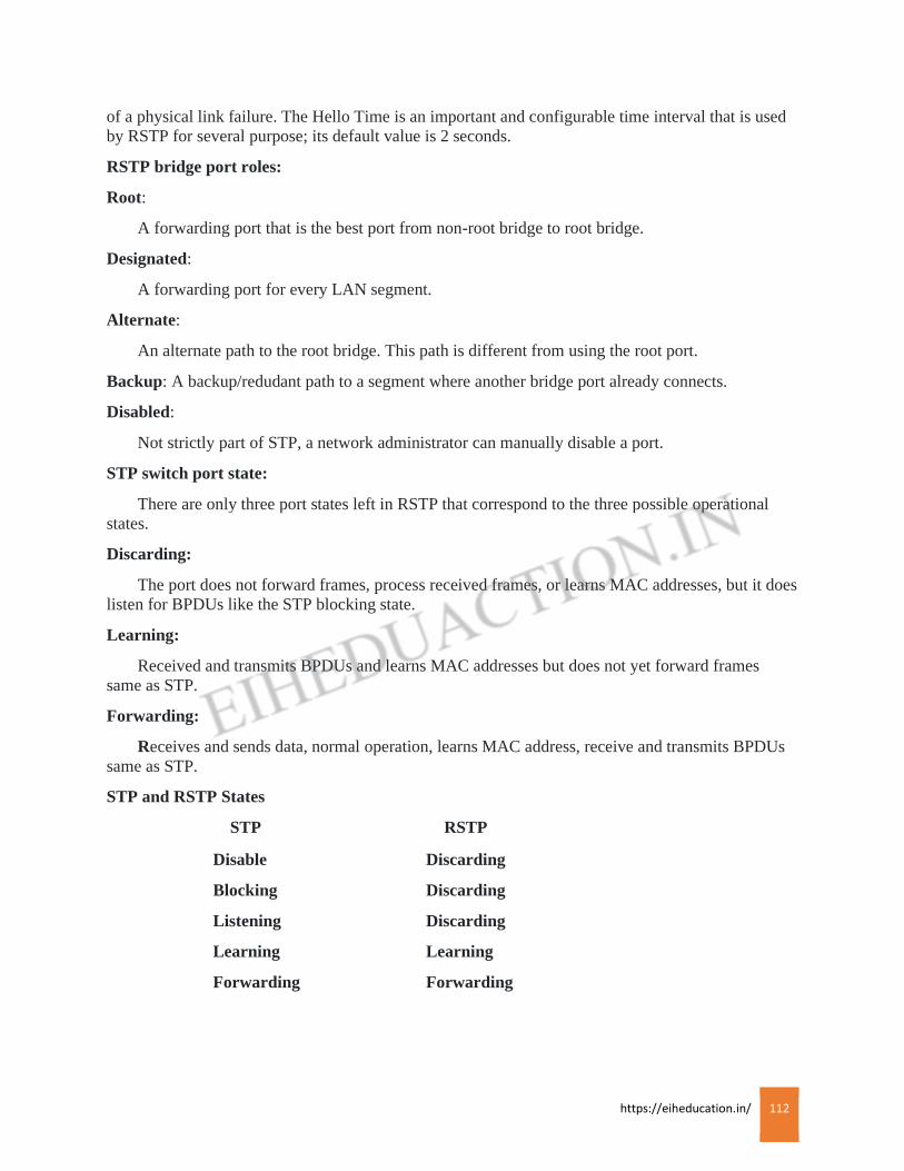
https://eiheducation.in/ 112
of a physical link failure. The Hello Time is an important and configurable time interval that is used
by RSTP for several purpose; its default value is 2 seconds.
RSTP bridge port roles:
Root:
A forwarding port that is the best port from non-root bridge to root bridge.
Designated:
A forwarding port for every LAN segment.
Alternate:
An alternate path to the root bridge. This path is different from using the root port.
Backup: A backup/redudant path to a segment where another bridge port already connects.
Disabled:
Not strictly part of STP, a network administrator can manually disable a port.
STP switch port state:
There are only three port states left in RSTP that correspond to the three possible operational
states.
Discarding:
The port does not forward frames, process received frames, or learns MAC addresses, but it does
listen for BPDUs like the STP blocking state.
Learning:
Received and transmits BPDUs and learns MAC addresses but does not yet forward frames
same as STP.
Forwarding:
Receives and sends data, normal operation, learns MAC address, receive and transmits BPDUs
same as STP.
STP and RSTP States
STP RSTP
Disable Discarding
Blocking Discarding
Listening Discarding
Learning Learning
Forwarding Forwarding
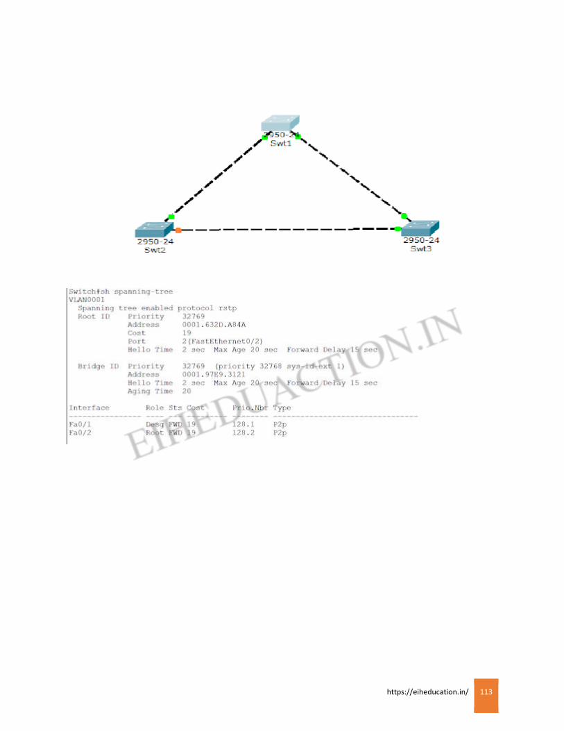
https://eiheducation.in/ 113
https://eiheducation.in/ 114
Working of Switch
Working of Switch
Ethernet LAN switches use a very cool system called transparent bridging to create their address
lookup tables. Transparent bridging is a technology that allows a switch to learn everything it needs
to know about the location of nodes.
Transparent bridging has five parts:
Learning
Flooding
Forwarding
Filtering
Aging
Suppose, A computer (node A) on the first segment (segment A) sends data to a computer (Node B)
on another segment (segment C).
The switch gets the first packet of the data from Node A. It reads the MAC address and saves it to the
lookup table for segment A. The switch now knows where to find Node A anytime a packet is
addresses to it. This process is called Learning.
Since the switch does now know where Node B is, it sends the packet to all the segments except the
one that it arrived on (Segment A). When a switch sends a packet out to all segment to find a specific
node, it is called Flooding.
Node B gets the packet and sends a packet back to Node A in acknowledgement.
The packet from Node B arrives at the switch. Now the switch can add the MAC address of Node B
to the lookup table for segment C. Since the switch already knows the address of Node A, it sends the
packet directly to it. Because Node A is on a different segment than Node B, the switch must connect
the two segments to send the packet. This is known as Forwarding.
The next packet from Node A to Node B arrives at the switch. The switch now has the address of
Node B too, so it forwards the packet directly to Node B.
Node C sends information to the switch for Node A. The switch looks at the MAC address for Node
C and adds it to the lookup table for segment A. The switch already has the address for Node A and
determines that both nodes are on the same segment, so it does not need to connect segment A to
another segment for the data to travel from Node C to Node A. therefore, the switch will ignore
packets travelling between nodes on the same segment. This is Filtering.
Learning and flooding continue as the switch add nodes to the lookup tables. Most switches have
plenty of memory in a switch for maintaining the lookup tables; but to optimize the use of this
memory, the y still remove older information so that the switch doesn’t waste time searching through
stale addresses. To do this, switches use a technique called Aging. Basically, when an entry is added
to the lookup table for a node, it is given a configurable timer that erases the entry after a certain
amount of time with no activity from that node. This frees up value able memory resources for other
entries. Transparent bridging is a great and essentially maintenance-free way to add and manage all
the information a switch needs https://eiheducation.in/ to do its job.
https://eiheducation.in/ 115
Port Security
Port Security
All interfaces on a Cisco switch are turned on by default. This means that an attacker could
connect his laptop to your network through a wall socket and potentially perform an attack on your
network. Luckily, there is a feature on Cisco switches called port security that can help you mitigate
the threat.
With port security, you an associate specific MAC addresses with specific interfaces on your switch.
This enables you to restrict access to an interface so that only the authorized devices can use it. If an
unauthorized device is connected, you can decide the action that the switch will take, such as
discarding the traffic, sending an alert, or shutting down the port.
Three steps are required to configure port security.
Defining the interface as an access interface using the switchport mode access interface
subcommand.
Enabling port security using the switchport port-security interface subcommand.
Defining which MAC addresses are allowed to send frames through this interface using the
switchport port-security mac-address MAC_ADDRESS interface subcommand or using the
switchport port-security mac-address sticky interface subcommand. The sticky keyword instruct the
switch to dynamically learan the MAC address of the currently connected host.
Two steps are optional:
Defining the action that the switch will take when a frame from an unauthorized device is received.
This is done using the port security violation interface subcommand. All options discard the traffic
from the unauthorized device. the restrict and shutdown options send a log messages when a
violation occurs. Shutdown mode also shuts down the port.
Defining the maximum number of MAC address that can be received on the port using the switchport
port-security maximum NUMBER interface submode command.
Example: Host A is connected to Fa0/1 on SW1. To enable port security on Fa0/1, we need to define
the port as an access port, enable port security and define which MAC addresses are allowed to send
frames through this interface. We can do this with the following set of commands:
Sw1(config)#int fa0/1
Sw1(config-if)#switchport mode access
Sw1(config-if)#switchport port-security
Sw1(config-if)#switchport port-security mac-address sticky
Using the show port-security interface fa0/1 command on sw1, we can see that the switch has learned
the MAC address of Host A.
By default, the maximum number of allowed MAC address is one. Consider what happens if we
connect a different host to the same port.
By default, if a security violation occurs, the switch will shut down the offending port. To enable the
port, you need to enter the shutdown and no shutdown interface subcommands.
https://eiheducation.in/ 116
VLAN
VLAN
A Virtual Local Area Network (VLAN) is a logical grouping of network users and resources
connected to administratively defined ports on a switch. VLAN’s separate a Layer-2 switch into
multiple broadcast domains. Each VLAN is its own individual broadcast domain. Individual ports or
groups of ports can be assigned to a specific VLAN. Only ports belonging to the same VLAN can
freely communicate to each other. A router or layer 3 switch is needed for inter-
VLAN communication.
Broadcasts from one VLAN will never be sent out to ports belonging to another VLAN.
In simple terms, a VLAN is a set of workstations within a LAN that can communicate with each
other as though they were on a single, isolated LAN.
By default, all Ethenet interface on Cisco switches are on VLAN 1. On Catalyst switches all of these
VLANs listed above default to VLAN 1, which can add to the difficulty of understanding their
differences.
Types of VLANs
Static VLANs:
In a static VLAN, the network administrator creates a VLAN and then assign switch ports to the
VLAN. Static VLANs are also called port-based VLANs. The association with the VLAN does not
change until the administrator changes the port assignment. End-user devices become the member of
VLAN based on the physical switch port to which they are connected.
Dynamic VLANs:
Dynamic VLANs determine a node’s VLAN assignment automatically. Using intelligent
management software, you can enable hardware (MAC) addresses, protocols, or even applications to
create dynamic VLANs.
Example: suppose MAC addresses have been entered into a centralized VLAN management
application. If a node is then attached to an unassigned switch port, the VLAN management database
can look up the hardware address and assign and configure the switch port to the correct VLAN.
This can make management and configuration easier for the administrator. If a user moves, the
switch will automatically assign them to the correct VLAN. however, more administration is needed
initially to set up the database. Cisco administrators can use the VLAN Management Policy Server
(VMPS) service to set up a database of MAC addresses that can be used for dynamic addressing of
VLANs. VMPS is a MAC address-to-VLAN mapping database.
The reserve VLAN available 1002, 1003, 1004, 1005.
1002 – FDDI default-fiber data distribute interchange
1003 – Token Ring
1004 – FDDI Net
1005 – Token Ring Net
4094 – Transparent switch.

https://eiheducation.in/ 117
for access mode
sw1#vlan database
sw1(vlan)#vlan 2 name ccna
sw1(vlan)#vlan 3 name ccnp
sw1(vlan)#vlan 4 name ccie
sw1#show vlan (for verification)
sw1(config)#int f0/1
sw1(config-if)#switchport mode access
sw1(config-if)#switchport access vlan 2
sw1(config)#int f0/2
sw1(config-if)#switchport mode access
sw1(config-if)#switchport access vlan 2
sw1(config)#int range f0/3-f0/4
sw1(config-if)#switchport mode access
sw1(config-if)#switchport access vlan 3
sw1(config)#int range f0/5-f0/6
sw1(config-if)#switchport mode access
sw1(config-if)#switchport access vlan 4
(trunk)
sw1(config)#int range f0/7
sw1(config-if)#switchport mode trunk
sw1(config-if)#switchport trunk allowed vlan all
https://eiheducation.in/ 118
Inter- VLAN
Inter- VLAN
Inter-VLAN Routing can be defined as a way to forward traffic between different VLANs by
implementing a router in the network. VLANs logically segment the switch into different subnets,
when a router is connected to the switch, an administrator can configure the router to forward the
traffic between the various VLANs forwards traffic to the router which then forwards the traffic to
the destination network regardless of the VLAN configured on the switch.
There are two ways in which inter-VLAN routing can be accomplished.
Traditional inter-VLAN routing
Router-on-a-stick
Traditional inter-VLAN routing:
In this type of inter-VLAN routing, a router is usually connected to the switch using multiple
interface, one for each VLAN. The interface on the router are configured as the default gateway for
the VLANs configured on the switch the ports that connect to the router from the switch are
configured in access mode in their corresponding VLANs.
When a user node sends a message to a user connected to a different VLAN, the message moves
from their node to the access port that connects to the router on their VLAN. When the router
receives the packets, it examines the packets destination IP address and forwards it to the correct
network using the access port for the destination VLAN. The switch now can forward the frame to
the destination node since the router changed the VLAN information from the source VLAN to the
destination VLAN.
In this form of inter-VLAN routing, the router has to have as many LAN interface as the number of
VLANs configured on the switch. Therefore, if a switch has 10 VLANs, the router should have the
same number of LAN interface.
Inter-VLAN routing using router-on-a-stick:
In Inter-VLAN routing using Router-on-a-stick, the router is connected to the switch using a
single interface. The switch port connecting to the router is configured as a trunk link. The single
interface on the router is then configured with multiple IP addresses that correspond to the VLANs
on the switch. This interface accepts traffic from all the VLANs and determines the destination
network based on the source and destination IP in the packets. It then forwards the data to the switch
with the correct VLAN information.
In this type of inter-VLAN routing, the interface connecting the router to the switch is usually a trunk
link. The router accepts traffic that is tagged from the VLANs on the switch through the trunk link.
On the router, the physical interface is divided into smaller interface called sub-interfaces. When the
router receives the tagged traffic, it forward the traffic out to the sub-interface that has the destination
IP address. Sub-interfaces aren’t real interfaces but they use the LAN physical interfaces on the
router to forward data to various VLANs. Each sub-interfaces is configured with an IP address and
assigned a VLAN based on the design.
https://eiheducation.in/ 119
VTP
VTP
The VLAN Trunking Protocol is organized into management domains. A VTP domain is one
switch or several interconnected switches sharing the same VTP environment. A switch can be
configured only in one VTP domain. Switches in different VTP domains do not share VTP
information.
Switches in a VTP domain advertise many VLAN attributes to their VLAN VTP domain neighbors.
These VLAN advertisement contain information about the VTP management domain. VTP revision
number, available VLANs, and other VLAN parameters.
VTP Modes:
A network switch, which is participating in VLAN Trunking Protocol, can have three different
modes.
Server Mode
Client Mode
Transparent Mode
VTP Server Mode:
VTP server mode is the default VTP mode for all Crystal switches. At least one server is
required in a VTP domain to propagate VLAN information within the VTP domain. We can create,
add, or delete VLANs of a VTP domain in a switch which is in VTP server mode and change VLAN
information in a VTP server. The changes made in a switch in server mode are advertised to the
entire VTP domain.
VLAN Trunking Protocol Client Mode:
VTP client mode switches listen to VTP advertisement from other switches and modify their
VLAN configuration accordingly. A network switch in VTP client mode requires a server switch to
inform it about the VLAN changes. We cannot create, add or delete VLANs in a VTP client.
VLAN Trunking Protocol Transparent Mode:
VTP transparent mode switches do not participate in the VTP domain, but VTP transparent
mode switches can receive and forward VTP advertisement through the configured trunk links.
VTP Advertisement message:
Once the VTP is configured on the switches, the switches start advertising VTP information
between them on their trunks ports. The main information which the switches advertise are
management VTP Domain name, configuration revision number and the configured VLANs. VTP
advertisement are sent as multicast Ethernet frames and all neighbor devices receive the Ethernet
frames.
There are three types of VTP advertisement message;
https://eiheducation.in/ 120
Client advertisement request:
A client advertisement request message is a VTP message which a client generates for VLAN
information to a server. Servers respond with both summary and subset advertisement.
Summary advertisement request:
Summary advertisement are sent out every 300 second (5 minutes) by default or when a
configuration change occurs, which is the summarized VLAN information.
Subset advertisement:
Subset advertisement are sent when a configuration change take place on the server switch.
Subset advertisement are VLAN specific and contain details about ach VLAN.
VLAN Trunking Protocol Pruning:
VTP is used to communicate VLAN information between switches in the same VTP domain.
VTP pruning is a feature in Cisco switches, which stops VLAN update information traffic from being
sent down trunk links if the updates are not needed. If the VLAN traffic is needed later, VTP will
dynamically add the VLAN back to the trunk link.
In normal operation a switch needs to floods broadcast frames, multicast frames, or unicast frames
where the destination MAC address is unknown to all its ports. If the neighboring switch doesn’t
have any active ports in the source VLAN, this broadcast is unnecessary and excessive unwanted
traffic is may create problems on the network. VTP pruning helps in increasing the available
bandwidth by reducing unnecessary flooded traffic. Broadcast frame, multicast frames, or unicast
frames where the destination MAC address is unknown https://eiheducation.in/are forwarded over a
trunk link only if the switch on the receiving end of the trunk link has ports in the source VLAN.

https://eiheducation.in/ 121
Frame Tagging
Frame Tagging
Frame tagging is used to identify the VLAN that the frame belongs to in a network with multiple
VLANs. The VLAN ID is placed on the frame when it reaches a switch from an access port, which is
a member of a VLAN. That frame can then be forwarded out the trunk link port. Each switch can see
what VLAN the frame belongs to and can forward the frame to corresponding VLAN access ports or
to another VLAN trunk port.
Before forwarding a tagged frame to an end host, the switch will remove the VLAN ID and the
VLAN membership information, since end host devices don’t understand tagging.
Two trunking protocols are usually used today for frame tagging:
Inter-Switch Link (ISL) – Cisco’s proprietary VLAN tagging protocol.
IEEE 802.1q – IEEE VLAN tagging protocol. Since it is an open standard, it can be used for tagging
between switches from different vendors.
Example: There are two VLANs in the topology. VLAN 5 and VLAN 10. Host C sends a broadcast
packet to switch SW1. Switch SW1 receives the packet, tags the packet with the VLAN ID of 5 and
sends it to SW2. SW2 receives the packet, looks up at the VLAN ID, and forwards the packet only
out the port in VLAN 5. Host A and Host B will not receive the packet because they are in different
VLAN (VLAN 10).
https://eiheducation.in/ 122
Inter – Switch Link (ISL):
Inter – Switch Link (ISL) is a Cisco proprietary protocol for frame tagging. Since it is a
proprietary protocol, it can be used only between Cisco switches. It supports up to 1000 VLANs and
can be used over Fast Ethernet and Gigabit Ethernet links only.
ISL works by encapsulating an Ethernet frame is an ISL header and trailer. The encapsulated frame
remains unchanged. The VLAN ID is included in the ISL header.
Original frame:
Destination MAC Source MAC Length/type Data FCS
ISL encapsulates the frame:
ISL Header Destination MAC Source MAC Length/ type Data FCS ISL FCS
ISL Is considered to be deprecated, and some newer Cisco switches don’t even support it. 802.1q is
commonly used instead.
802.1q:
802.1q us a VLAN tagging protocols developed by IEEE (Institute of Electrical and Electronics
Engineers). Since it is an open standard, it can be used between switches from different vendors, so if
you are trunking between a Cisco switch and a different brand of switch, you’ve can use Unlike ISL,
which encapsulates the whole frame in a ISL header and trailer, 802.1q insert an extra 4-byte 802.1q
VLAN field into the original frames Ethernet header. The 802.1q field includes the 12-but VLAN ID
field, which specifies the VLAN to which the frame belongs. 802.1q tagged frame can carry
information for 4,094 VLANs.
Original frame
Destination MAC Source MAC Length/type Data FCS
802.1Q frame:
Destination MAC 802.1Q Tag Source MAC Length/ type Data FCS
802.1q defines one special VLAN ID on each trunk as the native VLAN (by default VLAN 1).
802.1q does not add an 802.1Q header to frame in the native VLAN when the switch on the other
side of the trunk receives a frame that does not have an 802.1q header, the receiving switch knows
that the frame is part of the native VLAN. Because of this behavior, both switches must agree on
switch VLAN is the native VLAN.
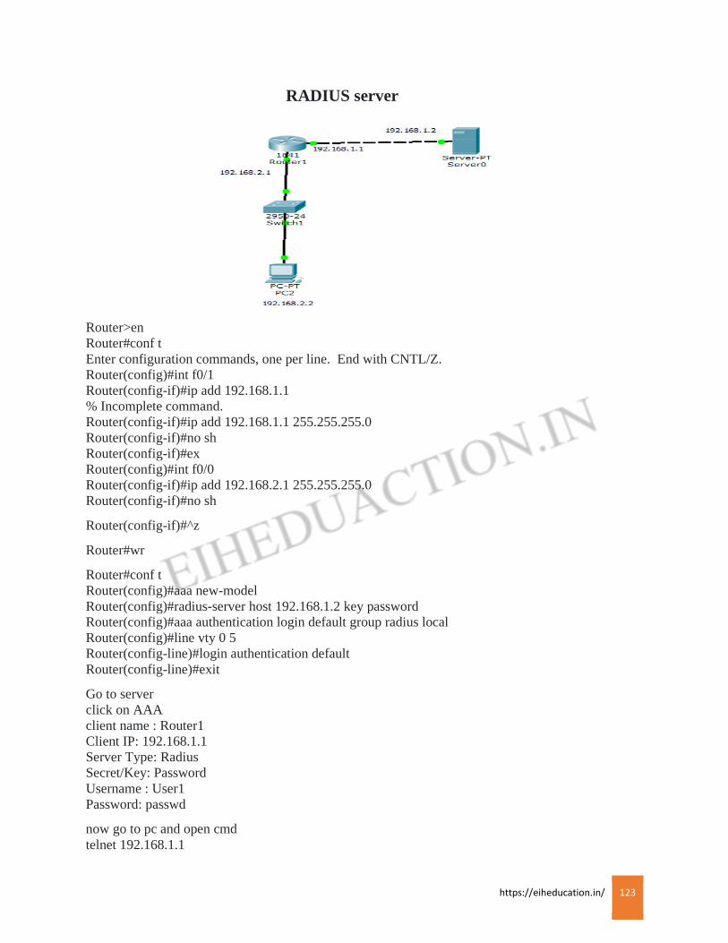
https://eiheducation.in/ 123
RADIUS server
Router>en
Router#conf t
Enter configuration commands, one per line. End with CNTL/Z.
Router(config)#int f0/1
Router(config-if)#ip add 192.168.1.1
% Incomplete command.
Router(config-if)#ip add 192.168.1.1 255.255.255.0
Router(config-if)#no sh
Router(config-if)#ex
Router(config)#int f0/0
Router(config-if)#ip add 192.168.2.1 255.255.255.0
Router(config-if)#no sh
Router(config-if)#^z
Router#wr
Router#conf t
Router(config)#aaa new-model
Router(config)#radius-server host 192.168.1.2 key password
Router(config)#aaa authentication login default group radius local
Router(config)#line vty 0 5
Router(config-line)#login authentication default
Router(config-line)#exit
Go to server
click on AAA
client name : Router1
Client IP: 192.168.1.1
Server Type: Radius
Secret/Key: Password
Username : User1
Password: passwd
now go to pc and open cmd
telnet 192.168.1.1
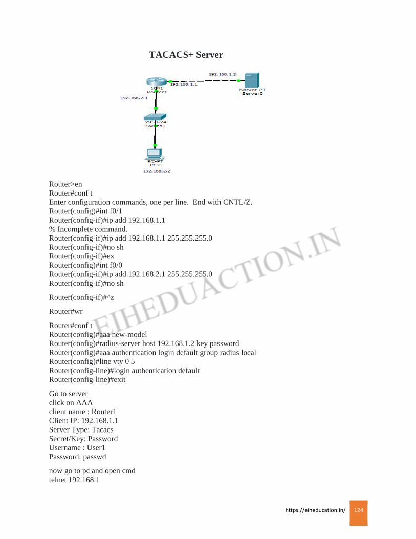
https://eiheducation.in/ 124
TACACS+ Server
Router>en
Router#conf t
Enter configuration commands, one per line. End with CNTL/Z.
Router(config)#int f0/1
Router(config-if)#ip add 192.168.1.1
% Incomplete command.
Router(config-if)#ip add 192.168.1.1 255.255.255.0
Router(config-if)#no sh
Router(config-if)#ex
Router(config)#int f0/0
Router(config-if)#ip add 192.168.2.1 255.255.255.0
Router(config-if)#no sh
Router(config-if)#^z
Router#wr
Router#conf t
Router(config)#aaa new-model
Router(config)#radius-server host 192.168.1.2 key password
Router(config)#aaa authentication login default group radius local
Router(config)#line vty 0 5
Router(config-line)#login authentication default
Router(config-line)#exit
Go to server
click on AAA
client name : Router1
Client IP: 192.168.1.1
Server Type: Tacacs
Secret/Key: Password
Username : User1
Password: passwd
now go to pc and open cmd
telnet 192.168.1
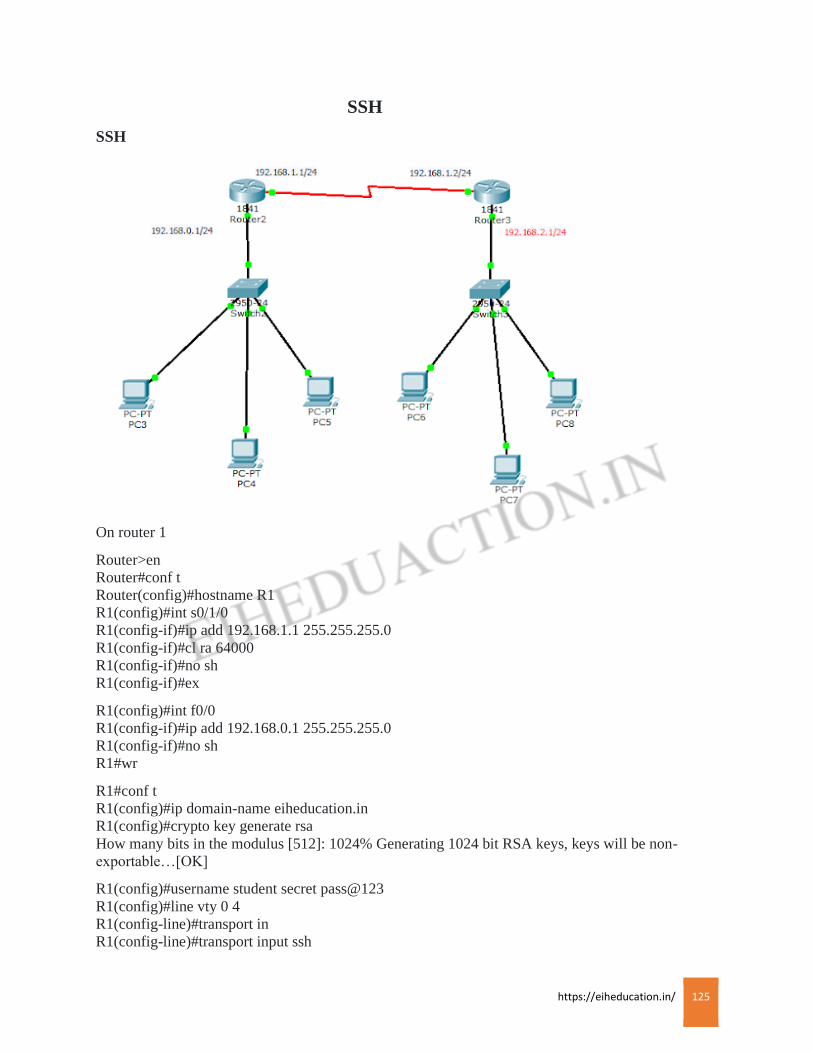
https://eiheducation.in/ 125
SSH
SSH
On router 1
Router>en
Router#conf t
Router(config)#hostname R1
R1(config)#int s0/1/0
R1(config-if)#ip add 192.168.1.1 255.255.255.0
R1(config-if)#cl ra 64000
R1(config-if)#no sh
R1(config-if)#ex
R1(config)#int f0/0
R1(config-if)#ip add 192.168.0.1 255.255.255.0
R1(config-if)#no sh
R1#wr
R1#conf t
R1(config)#ip domain-name eiheducation.in
R1(config)#crypto key generate rsa
How many bits in the modulus [512]: 1024% Generating 1024 bit RSA keys, keys will be non-
exportable…[OK]
R1(config)#username student secret pass@123
R1(config)#line vty 0 4
R1(config-line)#transport in
R1(config-line)#transport input ssh
https://eiheducation.in/ 126
R1(config-line)#login local
R1(config-line)#exit
On router 2
Router>en
Router#conf t
Router(config)#hostname R2
R2(config)#int s0/1/1
R2(config-if)#ip add 192.168.1.2 255.255.255.0
R2(config-if)#no sh
R2(config)#int f0/0
R2(config-if)#ip add
R2(config-if)#ip add 192.168.2.1 255.255.255.0
R2(config-if)#no sh
R2(config-if)#^z
R2#wr
R2#ssh -v 2 -l student 192.168.1.1
https://eiheducation.in/ 127
Wireless
Wireless
3 group of wireless technologies we have
1) Narrow band
2) Broadband
3) Circuit data solution
Narrow band technology is commonly use for WLAN,
900 MHz, 2.4 GHz, and 5 GHz this 3 frequencies comes under narrow band technologies
House hold cordless phone works on one of this frequency
IT is impossible to detect collision in wireless medium. WLAN uses technology called as CSMA/CA
(carrier sense multiple access/collision avoidance), in LAN we are using CSMA/CD.
WLAN device can not send or receive message simultaneously
To avoid collision in WLAN, device will use RTS (ready to send) and CTS (clear to send) signals.
When device want to transmit, it sense airwaves for current signal, if there is no signal then device
will send RTS signal this will indicate that data is about to send. After finishing data transmission
device will send clear to send signal in air waves and this will indicate that another device can send
data now
3 main factors influence signal distortion:
Absorption: – Absorb the RF waves; this is cause by wall, ceiling and floors.
Scattering: – Scatters the RF signals; this is cause by carpet on floor, rough plaster on the floor
Reflection: – Reflects the RF signals; this is cause by metal and glass
WLAN are implemented in IEEE 802.11 standard
Wireless communication can use various RF bands. Some of these are licensed and some are
unlicensed. 802.11 uses unlicensed bands, so you don’t have to buy license from the government to
buy these frequencies WLAN uses three unlicensed bands :
900Mhz used by older cordless phone
2.4Ghz used by newer cordless phone, WLANs, bluetooth, microwaves
5Ghz used by newest model cordless phone and WLAN devices
The advantage of using unlicensed bands for wireless is that you, as a company don’t need to pay
government to use these frequencies, main drawback is that many type of devices use them which
can create interference for WLAN device using the same RF band
WLAN standards
OFDM: – Orthogonal frequency division multiplexing
DSSS: – Direct sequence spread spectrum
MIMO: – Multiple input multiple output

https://eiheducation.in/ 128
WLAN NIC access a LAN or other wireless service via an access point (AP). To allow clients to
find the AP easily , AP periodically broadcast the beacons, announcing its SSID (service set
identifier), data rates and other WLAN information. SSID is a naming scheme for WLANs to allow
administrator to group WLAN device together
To discover AP client will scan all channels and listen for the beacons from the AP, by default client
will associate it self with the AP that has the strongest signal, When client associates it self with AP,
it sends the SSID, its MAC address, and any other security information that AP might require based
on authentication configured on two devices
WLAN security
802.11 defines only two authentication methods for APs to authenticate clients :
Open authentication : Exchanging four hello packets that contain no information (basically no
security at all)
Shared key authentication : A static key is used with WEP (wireless equivalency policy)
WEP: –
This is first security solution for wireless developed in 1997, WEP uses 64 bit static key (where the
key is 40 bits long, and a 24bit initialization vector (IV) used)
WEP uses RC4 as an encryption algorithm & IV is sent in clear-text WEP can be broken very easily
802.1XEAP:-
Extensible authentication protocol
EAP is a layer 2 process which allows a wireless client to authenticate to the network. Three standard
defines this process: EAP, 802.1x, and remote authentication dial in user service (RADIUS) . EAP
defines a standard way of encapsulating authentication information, such as username and password
or a digital certificate that the AP can use to authenticate the user
WPA – WIFI protocol access
Authentication is handled by 802.1x and TKIP is used with WEP
TKIP: – temporal key integrity protocol. Every packet will have unique encryption key and every
packet will be digitally signed to validate source of sender before decrypting. This is to make sure
that packet is valid and packet is not coming from untrusted source
WPA can operate in two modes
Personal and enterprise mode. Personal mode was designed for SOHO (small office home office)
usage, PSK (pre shared key) is used for authentication, with this no authentication server is
necessary. Enterprise mode is meant for large companies, where an authentication server will
centralize the authentication credential of the clients
https://eiheducation.in/ 129
WPA2
Instead of WEP which uses weak RC4 algorithm here AES-CCMP is used. AES-CCMP stands for
advanced encryption standard CBC counter mode MAC protocol
Router>enable
Router#configure terminal
Enter configuration commands, one per line. End with CNTL/Z.
Router(config)#interface FastEthernet0/0
Router(config-if)#ip address 192.168.0.1 255.255.255.0
Router(config-if)#no shutdown
Access point
Port 1: SSID – Name (EIHTECH)
Click on WEP
Set Key (10 digit): 9876543210
Remove module from pc and add Linksys module (wireless module)
PC0
IP Address : 192.168.0.2
Subnet Mask:255.255.255.0
Gateway: 192.168.0.1
PC1
IP Address : 192.168.0.3
Subnet Mask:255.255.255.0
Gateway: 192.168.0.1
Tablet PC0
IP Address : 192.168.0.4
Subnet Mask:255.255.255.0
Gateway: 192.168.0.1
End Device
IP Address : 192.168.0.5
Subnet Mask:255.255.255.0
Gateway: 192.168.0.1
https://eiheducation.in/ 130
WAN TECHNOLOGY
WAN
Typically LAN connection are used within company and WAN allow you to connect remote
location, With WAN you don’t own infrastructure for WAN connection, another company, such as
telephone company, cable provider provides the infrastructure. WAN connections are usually slower
than LAN connections.
WAN normally works at layer 2 of the OSI model.
DCE terminates a connection between sites and provides clocking and synchronization for that
connection; it connects to a DTE
DCE category includes equipment such as CSU/DSU (Channel service unit/ data service unit),
Network terminator type 1(NT1), and cable and analog modems. A DTE is an end user device, such
as router or pc which connects to the WAN via DCE
CSU/DSU terminates digital/synchronous circuits and modem terminates analog/synchronous
circuits.
Connection types
1) Leased line connections: –
Basically it is dedicated circuit connection between two sites. It simulates a single cable connection
between remote and local site
Leased line are best suited when both of these condition hold:
– The distance between the two site is small, making leased line cost effective
– A constant amount of traffic occur between two sites and you need to guarantee bandwidth for
certain applications
Even though leased line can provide guaranteed bandwidth and minimal delay for connection, other
available solution also can provide same, main disadvantage of leased line is their cost – they are
typically most expensive WAN solution, each connection will need separate interface on your router,
leased line use synchronous serial connection data rates is from 2400bps to 45Mbps.
Synchronous connection allow you to send and receive information simultaneously without having to
wait for any signal from the remote side, synchronous connection do not need to indicate when it is
beginning to send something or the end of transmission. These two things plus how clocking is done
are three major differences between synchronous and asynchronous connections, asynchronous
connections are typically used for dialup connections such as modems.
https://eiheducation.in/ 131
If your purchased leased line you will need following equipment:
DTE: A router with synchronous serial interface
DCE: A CSU/DSU to terminate the carrier’s leases line connection
2) Circuit switched connection : These are dial up connections, like those that are used by a pc with a
modem when dialing up an ISP.
Circuit switched includes following types
Asynchronous serial connection – These includes analog modem dial up connections
Synchronous serial connection : These includes digital ISDN , BRI and PRI dialup connections; they
provide guaranteed bandwidth
Asynchronous are the cheapest form of WAN services but are also the slowest and most unreliable of
the services, FCC (federal communications commision) restrict analog data rate to 53Mbps, main
problem of circuit switched is that they are expensive if you need to make connections over longer
distance, with a per minute charge that varies, depending on the destination: the more data you have
to send, more time it will take, more money you will have to pay.
If you will be using circuit switched analog connection, you will need this equipment :
DTE: A router with asynchronous serial interface
DCE : A modem
If you will be using circuit switched digital connection, you will need this equipment
DTE: A router with an ISDN interface
DCE :An NT1 for a BRI or a CSU/DSU for PRI
3) Packet switched connection
With leased line, and circuit switched connections, a physical circuit is used to make the connection
between two sites. With a leased line, the same circuit path is always used, with circuit switched path
is built every time a phone call is made, making it high probable that the same circuit path will not be
used for every phone call, packet switched connection uses logical circuit to make connections
between two sites. These logical circuit are referred as virtual circuits (VCs)
One advantage of logical circuit over physical one is that a logical circuit is not tied to any particular
physical circuit. Instead logical circuit is built across any available physical connection. Another
advantage of logical circuit is you can build many logical circuits over same physical circuit.
Technologies that use packet switching and logical circuits include ATM (asynchronous transfer
mode), frame-relay, X.25.
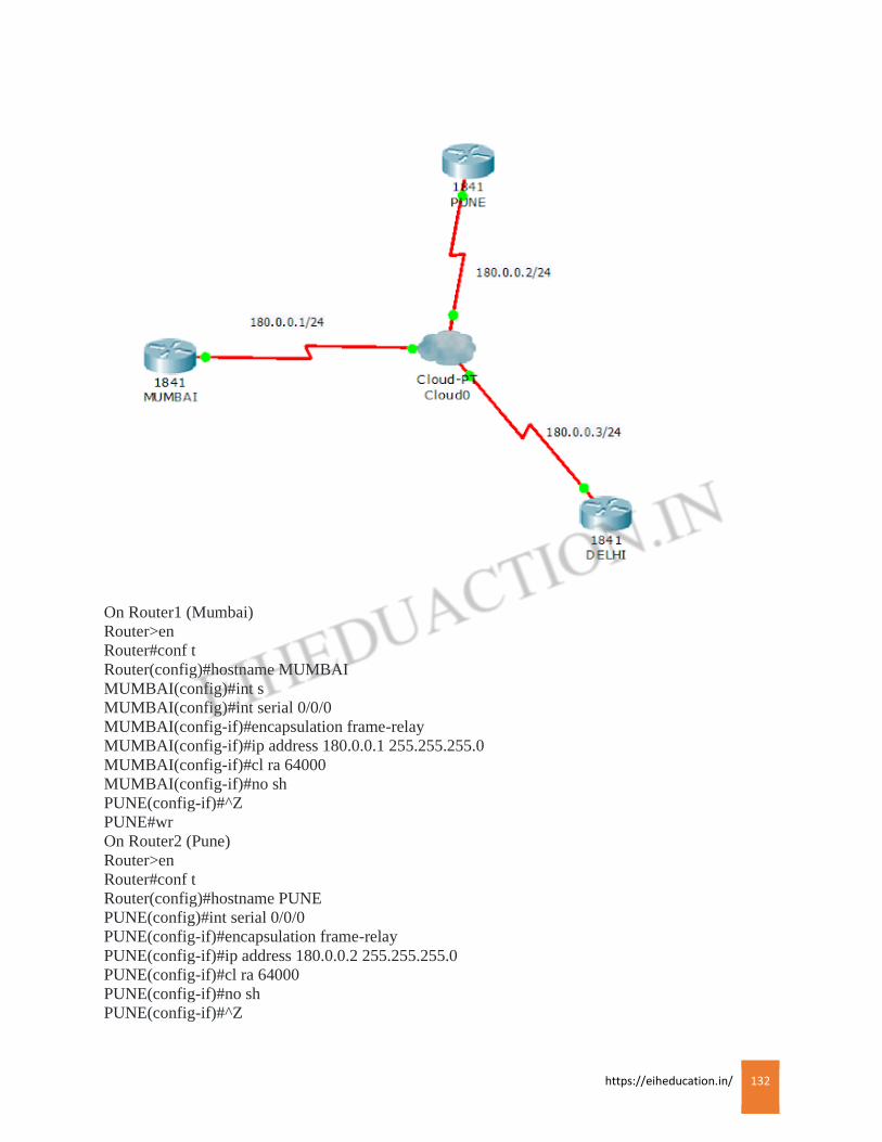
https://eiheducation.in/ 132
On Router1 (Mumbai)
Router>en
Router#conf t
Router(config)#hostname MUMBAI
MUMBAI(config)#int s
MUMBAI(config)#int serial 0/0/0
MUMBAI(config-if)#encapsulation frame-relay
MUMBAI(config-if)#ip address 180.0.0.1 255.255.255.0
MUMBAI(config-if)#cl ra 64000
MUMBAI(config-if)#no sh
PUNE(config-if)#^Z
PUNE#wr
On Router2 (Pune)
Router>en
Router#conf t
Router(config)#hostname PUNE
PUNE(config)#int serial 0/0/0
PUNE(config-if)#encapsulation frame-relay
PUNE(config-if)#ip address 180.0.0.2 255.255.255.0
PUNE(config-if)#cl ra 64000
PUNE(config-if)#no sh
PUNE(config-if)#^Z
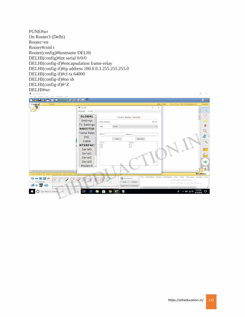
https://eiheducation.in/ 133
PUNE#wr
On Router3 (Delhi)
Router>en
Router#conf t
Router(config)#hostname DELHi
DELHI(config)#int serial 0/0/0
DELHI(config-if)#encapsulation frame-relay
DELHI(config-if)#ip address 180.0.0.3 255.255.255.0
DELHI(config-if)#cl ra 64000
DELHI(config-if)#no sh
DELHI(config-if)#^Z
DELHI#wr
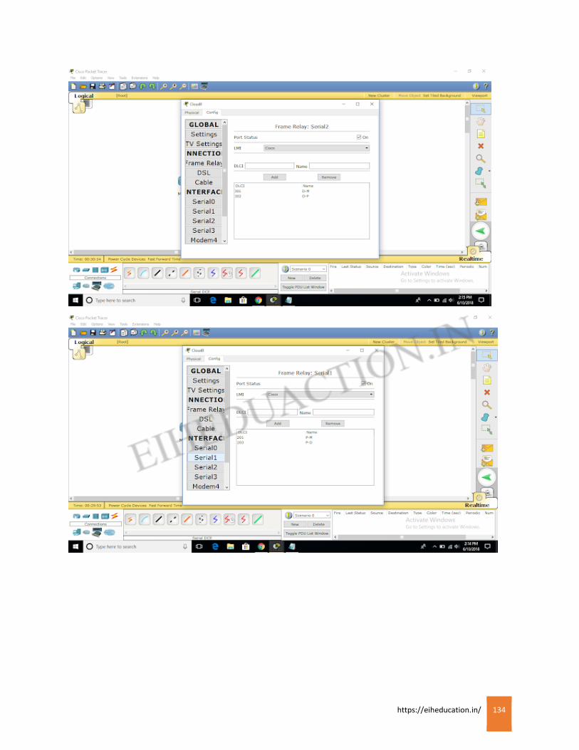
https://eiheducation.in/ 134

https://eiheducation.in/ 135

https://eiheducation.in/ 136
Encapsulation
Encapsulation
The sending and receiving of data from a source device to the destination device is possible with
the help of networking protocols by using data encapsulation. The data is encapsulated with protocol
information at each layer of the OSI reference model. Each layer communicates with its neighbor
layer on the destination. Each layer uses Protocol Data Units (PDUs) to communicate and exchange
information.
For example: Lets say that you are browsing a web site. The web server on which the website is
hosted will create and encapsulate the application data with the Application layer headers. For
example, the HTTP OK message will be stored in the header, followed by the requested content of
the web page.
The encapsulated data will then be forwarded to the next layer, the Transport layer. The Transport
layer will add its own header around the encapsulated data. In the case of the TCP protocol, this can
be something like the source and destination ports or the sequence number.
The data will then be forwarded to the next layer – the Network layer. The Network layer will store
the source and destination IP addresses in its header and forward the data to the Data Link Layer. The
Data Link Layer is the only layer that uses both the header and trailer.
The data is then sent through a physical network link.
De-Encapsulation
On destination side, the receiving devices will synchronize on the digital signal and extract the
1s and0s from the digital signal. At this point the devices build the frame, run a Cyclic Redundancy
Check (CRC), and then check their output against the output in the Frame Check Sequence (FCS)
field of the data frame, and the frame is discarded. This process is known as de-encapsulation. The
packet then transfer to the Network layer., where the IP address is checked. If the IP address matches
then the segment is pulled from the packet, and the packet is discarded. The data is processes at the
Transport layer that rebuilds the data stream ad acknowledges to the transmitting station that it
received each piece of segment. It then happily transfers the data stream to the upper layer
application.
DE capsulation
The tern de capsulation describes a process of removing headers and trailers as data passes from
a lower to the upper layer. This process transpires on a computer that is receiving data.
https://eiheducation.in/ 137
Encapsulation Method
Encapsulation Method
Cisco HDLC is based on ISO’s standard. One of the problem of with ISO’s HDLC is that
it does not define how to carry multiple protocols across single link, as does Cisco’s HDLC with
type field. The default encapsulation on Cisco’s synchronous serial interface is HDLC. Cisco
support only its own implementation of HDLC.
Configuring HDLC
#interface serial 0/0/0
#encapsulation HDLC
#control + Z
Verifying configuration
#show interface serial 0/0/0
PPP:
This is based on an open standard, PPP works with asynchronous and synchronous serial
connection as well as HSSI ( High speed serial interface) and ISDN interface (BRI and PRI ).
Features of PPP :
– Allows for authentication
– Compress packet header
– Test the quality of links
– Performs error detection and error correction
– Allows multiple physical connection to be bound together as a single logical connection
(Multilink)
PPP has three main components
– Frame format
– Link control protocol (LCP)
– Network control protocol (NCP)
Frame format we have seen earlier, LCP is responsible for establishing, authenticating and
testing PPP connection
LCP and NCP go through three steps to establish PPP connection:
1) Link establishment (LCP)
2) Authentication (LCP)
3) Protocol negotiation (NCP)
NCP negotiate upper layer protocols that will be carried across the PPP connection.
Configuring PPP:
#conf t
#int serial 0/0/0

https://eiheducation.in/ 138
#en ppp #control + z
Verifying configuration
#show interface serial 0/0/0
LCP and NCP should show as “open” state, this indicates that both protocols has successfully
negotiated it’s parameter
PPP authentication :
Two methods can be used to implement authentication PAP and CHAP
1) PAP (password authentication protocol)
2) CHAP (challenge handshaking authentication protocol)
Authentication is performed by LCP before the network and data link layer protocols are
negotiated for PPP connection by NCP. If authentication fails, data link layer will not come “up”
1) PAP :
This is simplest but least secure, PAP goes through two way handshake process. In this process
source sends its username (or hostname) and password, in clear text, to the destination. The
destination compares this information to a list of locally stored username and passwords, if it
find match destination sends back as “accept” message. If it doesn’t find a match, it sends back a
“reject” message.
Configuring Pap Authentication
Client configuration
#conf t
#int serial 0/0/0
#en ppp
#ppp pap sent-username <your host name> password <password>
Server side
#conf t
#username <remote hostname> password <matching password>
#int serial 0/0/0
#en ppp
#ppp authentication pa
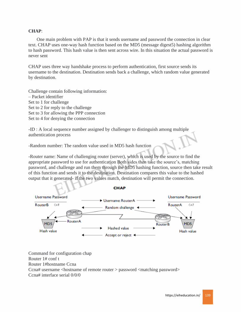
https://eiheducation.in/ 139
CHAP:
One main problem with PAP is that it sends username and password the connection in clear
text. CHAP uses one-way hash function based on the MD5 (message digest5) hashing algorithm
to hash password. This hash value is then sent across wire. In this situation the actual password is
never sent
CHAP uses three way handshake process to perform authentication, first source sends its
username to the destination. Destination sends back a challenge, which random value generated
by destination.
Challenge contain following information:
– Packet identifier
Set to 1 for challenge
Set to 2 for reply to the challenge
Set to 3 for allowing the PPP connection
Set to 4 for denying the connection
-ID : A local sequence number assigned by challenger to distinguish among multiple
authentication process
-Random number: The random value used in MD5 hash function
-Router name: Name of challenging router (server), which is used by the source to find the
appropriate password to use for authentication Both sides then take the source’s, matching
password, and challenge and run them through the MD5 hashing function, source then take result
of this function and sends it to the destination. Destination compares this value to the hashed
output that it generated- if the two values match, destination will permit the connection.
Command for configuration chap
Router 1# conf t
Router 1#hostname Ccna
Ccna# username <hostname of remote router > password <matching password>
Ccna# interface serial 0/0/0

https://eiheducation.in/ 140
Ccna (config-if) # encapsulation ppp
Ccna (config-if) # ppp authentication chap
router2#configure terminal
router2#hostname Ccnp
Ccnp# username <hostname of remote router > password <matching password>
Ccnp# interface serial 0/0/0
Ccnp (config-if)# encapsulation ppp
https://eiheducation.in/ 141
Frame Relay
Frame Relay
Frame-relay is layer 2 packet switching WAN technology, it is connection oriented: a layer 2
connection must be established before connection can be sent to remote device. The connections
used bye frame-relay are provided by virtual circuits (VCs), many VC can exist on same physical
interface. The advantage of VC that they can provide full connectivity at much lower price, VCs
are also full duplex
Advantages of VCs
Using frame relay you can have multiple logical circuits on same physical connection, you can
use same formula to calculate no. of VCs requirement, one nice feature of frame relay is that in
all of these situations, you need only one serial interface on each router to handle the VC
connections, you can easily use lower end router to handle lot of VC connections, frame relay
with VC is good solution if your router has a single serial interface, but needs to connect to
multiple WAN destination
There are two types of VCs
– Permanent VC (PVC)
– Switched or Semi permanent VC (SVC)
PVC is similar to leased line, SVC is dynamically built, and gets terminate after data has been
sent, SVC are used when data is sent periodically, CCNA syllabus is focusing on configuration
of PVC.
One advantage of PVC have over SVC is that SVCs must be setup when you have data to send, a
fact that introduces a small amount of delay before traffic can be sent to the destination.
One advantage of SVCs is that they are temporary. Therefore, since you are using SVC only part
of time , the cost of SVC is less than that of PVC
Common frame relay terms:
1) LMI 🙁 local management interface) this define how DTE (means your router) interact with
DCE (router connected to frame relay switch)
LMI is keep alive mechanism used between DTE and DCE to ensure that both are operational
and VC’s are not deleted or disable
2) DLCI: – data link connection identifier
This value is used to uniquely identify each VC on physical interface, using DLCI you can
multiplex traffic for multiple destination on a single physical interface. DLCI are locally
significant it can change on segment to segment basis
https://eiheducation.in/ 142
3) Access rate: – This is the speed of physical connection between your router and frame relay
switch
4) CIR: – Committed information rate
This is the average data rate measured over fixed period of time, that the carrier guarantee you
for particular VC
5) Bc: – Committed burst rate
It implies a smaller time period but a higher average than the CIR to allow for small burst traffic
6)Be :- Excessive bust rate
This is the fastest data rate at which provider will ever serve you the VC
7) DE: – Discard eligibility
This is use to mark frame as low priority frame
( frames exceeding Bc are marked as low priority frame)
8)Oversubscription :
when you add up all CIR of VC on an interface and if they exceed the access rate of your: you
are betting that all of your VCs will not run, simultaneously, at their rates
9) FECN:
(Forward explicit congestion notification)
This value in the frame header is set by carrier switch to indicate congestion inside carrier
network to destination device
10) BECN:
This value is set by DTE in header of frame relay frame to indicate congestion (from source to
destination) to source of frame relay
LMI
This is used locally between frame relay switch (DCE) and router (DTE)
As we have discussed earlier that LMI is keep alive mechanism
There are three different standards defined for LMI and its interaction with a frame relay DTE
and DCE
-ANSI
-Q933a
-Cisco
LMI type should be match between your router and frame relay switch