basic design study report on the project …open_jicareport.jica.go.jp/pdf/11761038_01.pdf · in...
TRANSCRIPT

GM JR
04 - 074
BASIC DESIGN STUDY REPORT ON
THE PROJECT FOR
UPGRADING OF ELECTRIC POWER SUPPLY IN
TARAWA ATOLL (PHASE II)
IN THE REPUBLIC OF KIRIBATI
MAY, 2004
JAPAN INTERNATIONAL COOPERATION AGENCY YACHIYO ENGINEERING CO., LTD.
No.

PREFACE
In response to a request from the Government of the Republic of Kiribati, the Government
of Japan decided to conduct a basic design study on the Project for Upgrading of Electric Power
Supply in Tarawa Atoll (Phase-II) in the Republic of Kiribati and entrusted the study to the
Japan International Cooperation Agency (JICA).
JICA sent to Kiribati a study team from November 24 to December 17, 2003.
The team held discussions with the officials concerned of the Government of Kiribati, and
conducted a field study at the study area. After the team returned to Japan, further studies were
made. Then, a mission was sent to Kiribati in order to discuss a draft basic design, and as this
result, the present report was finalized.
I hope that this report will contribute to the promotion of the project and to the
enhancement of friendly relations between our two countries.
I wish to express my sincere appreciation to the officials concerned of the Government of
the Republic of Kiribati for their close cooperation extended to the teams.
May, 2004
Yasuo Matsui
Vice-President
Japan International Cooperation Agency

LETTER OF TRANSMITTAL
May, 2004
We are pleased to submit to you the basic design study report on the Project for Upgrading
of Electric Power Supply in Tarawa Atoll (Phase-II) in the Republic of Kiribati.
This study was conducted by Yachiyo Engineering Co., Ltd., under a contract to JICA,
during the period from November, 2003 to May, 2004. In conducting the study, we have
examined the feasibility and rationale of the project with due consideration to the present
situation of Kiribati and formulated the most appropriate basic design for the project under
Japan's grant aid scheme.
Finally, we hope that this report will contribute to further promotion of the project.
Very truly yours,
Mitsuhisa Nishikawa Project Manager, Basic design study team on the Project for Upgrading of Electric Power Supply in Tarawa Atoll (Phase-II) in the Republic of Kiribati Yachiyo Engineering Co., Ltd.


LIST OF FIGURES & TABLES
[Figures] Fig. 2-2-1 Project Implementation Regime ................................................................... 74 Fig. 2-2-2 Project Implementation Schedule ................................................................. 77 Fig. 2-4-1 Basic Concept of Maintenance of Generating and Distribution Facilities ... 79 Fig. 2-4-2 Annual Operation Programme for New Generating Unit ............................. 80
[Tables] Table 2-2-1 Outline of Main Components of the Project ................................................. 15 Table 2-2-2 Outline of Rainwater Collection System ...................................................... 22 Table 2-2-3 Existing Systems Requiring Remodelling .................................................... 22 Table 2-2-4 Composition of Diesel Fuel Oil .................................................................... 23 Table 2-2-5 Engine Output and Generator Capacity ........................................................ 25 Table 2-2-6 Outline of Main Generating Equipment ....................................................... 33 Table 2-2-7 Main Remodelling Items for Existing Equipment/Systems ......................... 34 Table 2-2-8 Main Temporary Equipment/Systems........................................................... 35 Table 2-2-9 Outline of Main Distribution Equipment...................................................... 40 Table 2-2-10 Division of Work between Japanese Side and Kiribati Side......................... 72 Table 2-2-11 Equipment and Material Supply Sources...................................................... 76 Table 2-4-1 Standard Periodical inspection Items of Generating Facility ....................... 81 Table 2-4-2 Standard Periodical inspection Items for Distribution Facility..................... 83 Table 2-4-3 Spare Parts and Maintenance Tools to be Provided Under the Project......... 85 Table 2-5-1 Expected Operating Income and Expenditure for New Generating Unit ..... 89

ABBREVIATIONS
ADB Asian Development Bank
AIJ Architectural Institute of Japan
AusAID Australian Agency for International Development
A$ Australian Dollar(1 A$=78 Japanese Yen、As of December, 2003)
BHN Basic Human Needs
DAC Development Assistance Committee
DEG Diesel Engine Generator
EEZ Exclusive Economic Zone
EU European Union
E/N Exchange of Notes
GDP Gross Domestic Product
GNP Gross National Product
IEC International Electrotechnical Commission
ISO International Organization for Standardization
JEAC Japan Electric Association Code
JEC Japanese Electrotechnical Committee
JEM Standards of Japan Electrical Manufacturer's Association
JICA Japan International Cooperation Agency
JIS Japanese Industrial Standards
KOIL Kiribati Oil company
MELAD Ministry of Environment, Lands and Agricultural Development
MPWU Ministry of Public Works and Utilities
O&M Operation and Maintenance
OJT On the Job Training
PUB Public Utilities Board
SAPHE Sanitation, Public health and Environment
TSKL Telecommunication Services of Kiribati Ltd.

SUMMARY

S-1
SUMMARY
The Republic of Kiribati (hereinafter referred to as Kiribati) is an island country consisting of 33 atolls of various sizes which are dotted over a huge sea area extending on both sides of the Equator and the Date Line in the Pacific. It has a total land area of 810 km2, a population of approximately 84,000 (government statistics for 2000) and the nominal GDP per capita was US$ 664 in 2000. 98% of the people are Micronesians. Its EEZ is as large as 3 million km2 (more than eight times the land area of Japan).
Kiribati gained its independence from the UK in 1979 but the depletion of phosphate rock, which had been the source of its main industry, in the same year made the country economically dependent on such primary industries as agriculture, particularly the production of copra as the main export product, and fisheries (fish and seaweed). Its trade balance has been chronically in deficit due to the need to import food and most daily necessities because of the geographical and topographical restrictions and the government finance is extremely tight even today.
South Tarawa, which is the Project Area and where the capital of Bairiki is situated, is the centre of economic, industrial and administrative activities in Kiribati. Its population of 37,000 (2000) accounts for more than 40% of the country’s total population and is expected to steadily increase.
The electricity service in South Tarawa is operated and maintained by the Public Utilities Board (PUB) under the supervision of the Ministry of Public Works and Utilities (MPWU). Following the disposal of the Betio Power Plant No. 8 Unit at the end of 2002 following a fire incident, electricity is currently supplied by the remaining five generating units. However, three of these five units are more than 27 years old and their generating capacity has declined, making the enforcement of frequent, regular power cuts necessary. Accordingly, the power supply shortage and the decline of trust in the supply are highly apparent. This situation led to a decision at the beginning of 2003 to suspend new service connection to waiting users and, at the end of 2003, 401 households or approximately 10% of the original households in South Tarawa were unable to receive electricity supply. Moreover, the distribution facilities in Bairiki, the political centre of Kiribati, Betio, the centre of commercial activities, and the Bonriki District where the airport and water supply facilities are located have deteriorated as these areas were not included in the scope of the Japanese grant aid project implemented in FY 2001. The poor distribution conditions in these areas are illustrated by not only the insufficient distribution capacity but also the very high distribution loss of more than 16%.

S-2
In its National Development Strategy (2004 – 2007), the Government of Kiribati has decided to install one new generating unit (1,250 KW) to replace the Betio Power Plant No. 8 Unit which was disposed of following a fire as improvement of the generating and distribution facilities is necessary to remedy the pressing electricity supply shortage in the capital area. Although this unit is scheduled for completion in June, 2004, the Government of Kiribati is finding it extremely difficult to install an additional new generating unit(s) to realistically meet the increasing electricity demand, to enable the implementation of essential periodic inspections and to rehabilitate the distribution network because of financial difficulties. To rectify this situation, the Government of Kiribati has requested the Government of Japan’s provision of fresh grant aid for the development of electricity supply facilities.
In response to this request, the Government of Japan decided to conduct the Basic Design Study and the Japan International Cooperation Agency (JICA) sent the Basic Design Study Team to Kiribati for the period from 24th November to 17th December, 2003 to confirm and discuss the contents of the request with government officials of Kiribati, to conduct a project site survey and to gather relevant information and data.
On its return to Japan, the Study Team examined the necessity, social and economic effects and relevance of the project based on the field survey results and formulated the basic design and implementation plan for the optimal project. The JICA again sent the Study Team to Kiribati for the period from 2nd to 12th March, 2004 to explain the contents of the Basic Design Summary to the Kiribati side. The final proposed components of the project to be implemented by the Japanese side are outlined below.

S-3
Power Station Construction Plan (Construction of Power Station)
Distribution Network Upgrading Plan (Procurement and Installation of Distribution
Equipment and Materials)
At Bikenibeu Power Station in South Tarawa From Bairiki to Betio and Anana Causeway and Bonriki District in South Tarawa
<Construction Work> ・ Construction of powerhouse (approx. 400 m2) ・ Construction of foundations for generators, fuel
tanks and auxiliary machinery ・ Construction of rainwater storage tank ・ Construction of internal roads and outdoor lighting
around powerhouse ・ Construction of auxiliary facilities for powerhouse <Procurement and Installation of Generating Equipment>・ Procurement and installation of diesel generator
(1,400 KW x 1) ・ Procurement and installation of auxiliary
mechanical systems/equipment for generator - Fuel oil system (including oil tank) - Lubricant oil system - Cooling water system - Compressed air system - Intake air and exhaust gas system - Piping system
・ Procurement and installation of auxiliary electrical system/equipment for generator - 11 kV high voltage distribution panel - 415 V station power system - Monitoring/control panel and protective relay
panel - Wiring and grounding system
・ Procurement of spare parts for generators and auxiliary machinery and of machine tools
・ Procurement of O & M manuals for generating equipment (including textbooks for OJT) and implementation of OJT
・ Procurement and installation of the following distribution equipment - Rehabilitation of the 11 kV cable from East
Bairiki to Betio (approx. 12.9 km) - Rehabilitation of one 11 kV circuit breaker panel
and two distribution switchgears in the above section
- Rehabilitation of the 11 kV cable from the Anana Causeway to the Bonriki District (approx. 3.6 km)
- Rehabilitation of one 11 kV distribution switchgear and one distribution transformer in the above section
- One new distribution switchgear and new 11 kV cable for the section between the existing distribution switchgears (approx. 1.1 km)
・ Procurement of one 4 ton truck equipped with a 3 ton crane for maintenance purposes
・ Procurement of O & M manuals for distribution equipment (including textbooks for OJT) and implementation of OJT
Should the Project be implemented under the grant aid scheme of the Government of Japan, the total project cost is estimated to be approximately ¥815 million (Japanese portion of ¥797 million and Kiribati portion of ¥18 million. The Kiribati side will be responsible for the clearance and levelling of the ground at the planned installation sites for the generating and distribution facilities, preparation of an EIA report, securing of the land for the new distribution facilities and the construction of low voltage service lines to waiting users. The total project period, including the preparation of the detailed design, is estimated to be some 20 months.
The operation and maintenance of the new facilities and equipment in the post-project period will be conducted by the PUB which has an electricity division and a water supply and

S-4
sewerage division and which receives a government subsidy. The financial situation of the electricity division has been improving every year. It has sufficient basic technical capability to operate and maintain the diesel generating unit and 11 kV distribution network as it has received appropriate guidance from experts dispatched as part of the assistance for the maintenance of the generating and distribution facilities under the previous project. Accordingly, the proper maintenance of the new generating and distribution facilities to be installed under the Project is judged to be possible if the transfer of preventive maintenance skills regarding these facilities and the provision of the necessary operation and maintenance manuals are conducted during the period of installation up to the handing-over testing.
The implementation of the Project is expected to have the direct effects listed below. The population which will benefit from the implementation of the Project will be approximately 39,000 in South Tarawa and part of North Tarawa.
・ Assurance of stable electricity supply:
The present total generating capacity will increase by 1,400 KW to assure a stable supply of electricity.
・ Reduction of waiting users:
Some 400 ordinary households waiting for connection will be newly electrified.
・ Improved quality of electricity:
The voltage drop at the user end will be improved from more than 10% to below 5%, improving the quality of the electricity supplied.
・ Establishment of an efficient electricity supply system:
The current distribution loss (more than 16%) will be reduced to approximately 10%, establishing an efficient electricity supply system.
As the electricity newly generated under the Project will be supplied to users at a cost, the profitability of the operation of the PUB will be determined by the number of users, the amount of electric energy sold and the collection rate of the electricity charge. In regard to the operation costs of the new generating unit and distribution facilities after their commissioning, the business balance for the said unit is expected to produce a project once its annual operation rate exceeds 55% based on the current average electricity charge of the PUB (A$ 0.43/KWh). Once the break-even point is passed, it will be possible to set aside funds for the procurement of spare parts for the proper maintenance of the generating unit, making such

S-5
maintenance a reality. The expected profit, however, will be just enough to smoothly conduct the operation and maintenance of the facilities and equipment. The many positive effects expected of the Project and the broad contribution of the Project to satisfying BHN ascertain the suitability of the provision of Japanese grant aid for part of the Project. No problems are anticipated in terms of manpower and funding on the Kiribati side for the operation and maintenance of the Project-related facilities and equipment.
For the smoother and more effective implementation of the Project, the Kiribati side must complete the work for which it is responsible, including the installation of 415 V low voltage distribution cables, without delay. In addition, the PUB should formulate an economic operation plan for its generating and distribution facilities to ensure a stable supply of electricity. It is desirable for the PUB to periodically review the electricity supply and demand situation, to plan facility expansion and to implement measures designed to achieve more efficient electricity supply, energy saving and prolongment of the lives of the existing generating units, etc. so that the capacity to provide a stable supply of electricity can be boosted even after 2001, the target year of the Project.

CONTENTS
Preface Letter of Transmittal Location Map / Perspective List of Figures & Tables Abbreviations Summary
CHAPTER 1 BACKGROUND OF THE PROJECT........................................................... 1 CHAPTER 2 CONTENTS OF THE PROJECT .................................................................. 3
2.1 Basic Concept of the Project ...................................................................................... 3 2.2 Basic Design of the Requested Japanese Assistance.................................................. 3
2.2.1 Design Policy ......................................................................................................... 3 2.2.2 Basic Plan (Construction Plan/Equipment Plan).................................................. 10 2.2.3 Basic Design Drawings ........................................................................................ 41 2.2.4 Implementation Plan/Procurement Plan............................................................... 68
2.2.4.1 Implementation Policy/Procurement Policy............................................... 68 2.2.4.2 Implementation Conditions/Procurement Conditions................................ 69 2.2.4.3 Scope of Work ............................................................................................ 71 2.2.4.4 Work Supervision/Procurement Supervision Plan ..................................... 73 2.2.4.5 Quality Control Plan................................................................................... 75 2.2.4.6 Procurement Plan ....................................................................................... 76 2.2.4.7 Implementation Schedule........................................................................... 77
2.3 Obligations of Recipient Country ............................................................................ 77 2.4 Operation and Maintenance Plan ............................................................................. 79
2.4.1 Maintenance Plan ................................................................................................. 79 2.4.2 Operating Plan for New Generating Facility........................................................ 80 2.4.3 Periodic Inspection Items ..................................................................................... 81 2.4.4 Fuel Oil Procurement Plan ................................................................................... 83 2.4.5 Spare Parts Procurement Plan .............................................................................. 84
2.5 Estimated Project Cost ............................................................................................. 87 2.5.1 Estimated Project Cost ......................................................................................... 87 2.5.2 Operation and Maintenance Cost ......................................................................... 88
CHAPTER 3 PROJECT EVALUATION AND RECOMMENDATIONS ........................ 91
3.1 Project Effects .......................................................................................................... 91 3.2 Recommendations .................................................................................................... 92

Appendices 1. Member List of the Study Team 2. Survey Schedule 3. List of Parties Concerned in the Recipient Country 4. Minutes of Discussions 5. Cost Estimation Borne by the Recipient Country 6. Power Balance in Tarawa Power System 7. Power Flow Study

CHAPTER 1
BACKGROUND OF THE PROJECT

– 1 –
CHAPTER 1
BACKGROUND OF THE PROJECT
Following its independence in 1979, the Republic of Kiribati (hereinafter referred to as Kiribati) heavily relied on the financial support of the United Kingdom, its former suzerain state. Fiscal aid by the UK for Kiribati’s current budget, however, was terminated in 1986, making self-reliant public finance an urgent national task for the country. Kiribati has been attempting to develop its national economy, mainly focusing on the development of fisheries by means of the effective exploitation of the marine resources of its huge 200-mile EEZ. Meanwhile, the Tenth National Development Strategy and (2004 – 2007) National Development Strategy has adopted the development, improvement and expansion of social infrastructure to stimulate economic activities as a priority target. Nevertheless, the progress of infrastructure development has been slow even in South Tarawa, which is the economic, industrial and administrative centre of Tarawa. The slow progress is particularly noticeable in regard to the development of power supply facilities, which are essential for the stable operation of social and public facilities, such as hospitals and schools, and fishing facilities, including cold storages, and also for improvement of the standard of living of the public.
Under these circumstances, the Government of Kiribati made a request to the Government of Japan for the provision of grant aid for the procurement and installation of equipment and materials of new power generating and distribution facilities, which are essential for the implementation of the Project for Upgrading of Electric Power Supply in Tarawa Atoll (hereinafter referred to as the Project) in the country’s economic and social development centre.
[Contents of the Request]
(1) Procurement and Installation of Diesel Generating Unit
1) One set of diesel engine generator with an output of 1,400kW
2) Auxiliary mechanical systems required to operate 1) above
- Fuel and lubrication oil supply system, including fuel oil storage tank and daily tank - Cooling water system - Intake air and exhaust gas system - Piping, cabling and other materials required for the installation of the above systems
3) Electrical systems required for 1) and 2) above and station power source
- Remote control panels, including instrumentation and protective relay panels

– 2 –
- 11 kV high voltage panel - Auxiliary equipment for the new generating unit (station power and DC power
supply equipment, etc.) - Grounding system - Cabling and other materials required for the installation of the above
(2) Civil Engineering and Building Work at Bikenibeu Power Station necessary for item (1) above
1) Construction work to extend the existing powerhouse, including building services
2) Foundation work for the main and auxiliary equipment
3) Exterior work, including a rainwater drainage system, within the premises
(3) Procurement and Installation of 11 kV Distribution Systems (including Civil Engineering Work)
1) Upgrading of 11 kV distribution systems (including terminal treatment and connection materials for underground cables)
- Distribution line from the existing ring main unit (RMU 13) at East Bairiki to Betio (approximately 12.9 km)
- One circuit breaker (C/B 1) and two ring main units (RMU 13 and RMU 16) - Distribution line from Anana Causeway to Bonriki (approximately 3.6 km) - One switchgear (RMU 31) and one 100 kVA distribution transformer (T 31)
2) Construction of new 11 kV distribution systems (including terminal treatment and connection materials for underground cables)
- One ring main unit (RMU 64) - Distribution line from the above ring main unit (RMU 64) to the existing ring main
unit (RMU 39) at the Bonriki Water Supply Station (approximately 1.1 km)
(4) Procurement of Spare Parts, Maintenance Equipment and Tools Required for (1) and (3) Above
1) Procurement of consumables and spare parts required for two years operation
2) Procurement of maintenance/repair equipment and tools and vehicle
3) Procurement of operation and maintenance manuals

CHAPTER 2
CONTENTS OF THE PROJECT

– 3 –
CHAPTER 2
CONTENTS OF THE PROJECT
2.1 Basic Concept of the Project
(1) Objectives of the Project
In its National Development Strategies (2004 – 2007), the Government of Kiribati has adopted the economic growth of the country and the improvement of the living condition of the local residents as the two main strategic targets.
The present Project is considered to form part of the attempt to develop social infrastructure which is essential for the improvement of living standard for local people, the stable operation of social and public facilities and the vitalization of industry in South Tarawa, which is the centre of socioeconomic activities in Kiribati. The immediate objectives of the Project are the construction of generating facilities, the upgrading of a distribution network and the electrification of hitherto unelectrified areas to achieve a highly reliable and stable power supply.
(2) Outline of the Project
In order to achieve the above objectives, the Project plans to improve the existing power supply facilities in South Tarawa. The implementation of the Project is expected to achieve a stable power supply, which is an important component of the social infrastructure in South Tarawa, and to improve the reliability of power systems. The scope of the Japan’s grant aid covers the installation of one new 1,400kW generating unit on the premises of the existing Bikenibeu Power Station, upgrading of 16.5 km of 11 kV trunk distribution lines out of the total length of 62 km and the installation of 1.1 km of new 11 kV distribution lines.
2.2 Basic Design of the Requested Japanese Assistance
2.2.1 Design Policy
(1) Basic Concept
The basic principles for the determination of the basic framework, i.e. scope of the cooperation, site selection and scale of equipment, are described as below.
– 4 –
1) Scope of Cooperation
The scope of the cooperation under the Project will be the installation of a new generating unit (one 1,400kW), upgrading of 16.5 km of 11 kV trunk distribution lines to mitigate the voltage drop and distribution loss on the 11 kV distribution lines and the installation of a new 11 kV distribution line for 1.1 km to secure a stable power supply.
2) Site Selection
As the efficient use of the available sites of the existing power facilities and land owned by the government is intended, the new generating unit will be installed on the premises of the existing Bikenibeu Power Station. Both replaced and new 11 kV distribution cables will be buried alongside the existing road.
3) Capacity of Equipment
The capacity of equipment will be sufficient to secure the power balance between generation capacity and maximum demand, and to ensure an adequate distribution voltage and power loss in 2011, five years after completion of the Project.
4) Additional Generating Unit
The Project is basically planned in consideration of the efficient use of the existing facilities. During the implementation period of the Project, temporary stoppage of the existing generating units to allow the remodelling of various equipment and systems is inevitable. As the Bikenibeu Power Station is the main power station in Tarawa, its stoppage will have direct impact on social and economic activities. The minimisation of such impact will be given the highest priority during the implementation period of the Project. In addition, the expansion/remodeling plan must be economical and technically appropriate.
(2) Natural Conditions
1) Temperature and Humidity
The Project Area has a tropical climate with an almost constant temperature throughout the year. The maximum, minimum and mean temperatures were 34°C, 24°C and 28°C respectively. As the generating equipment to be procured under the Project will be installed inside a building, no special measures will be required regarding the ambient temperature or humidity. No special measure relating to temperature will be required for the distribution equipment which will be installed

– 5 –
outdoors as the difference between the maximum and minimum ambient temperatures of 10°C is small. As the design humidity is high (maximum of 98%, minimum of 60% and average of 75%), measures to prevent condensation will be employed to determine the exact equipment specifications, taking the maximum humidity of 98% into consideration. In view of the strong solar radiation, the use of highly light-resistant paint and the introduction of sunshading will be considered.
2) Wind and Rainfall
While the recorded maximum wind velocity is 21 m/sec, the mean annual wind velocity is 3 – 5 m/sec with a prevailing east wind. The mean annual rainfall is 2,300 mm but can exceed 4,000 mm in some years. There is hardly any distinction between the dry season and the rainy season. In connection with the installation of the new generating unit, rainwater drainage, etc. will be provided for the power station premises so that undrained rainwater will not disrupt the operation and maintenance of the generating facility. In case of the distribution facility, careful planning of the schedule for the excavation work for installing underground cables will be necessary, taking the period of relatively heavy rainfall from November to April into consideration. Although the frequency of some 15 thunderstorms a year which is not particularly high, a lightning rod will be installed on the roof of the power house to avoid lightning damage to the power house.
3) Salt Contamination
As the planned site for the new generating unit is situated on the coast as in the case of the previous project, the main equipment will be installed inside the building to protect it from salt contamination and also to reduce noise pollution in the surrounding area. Such auxiliary facilities as the radiator and fuel tank, etc. to be installed outdoors will apply a salt-resistant coating and other measures for their protection together with the use of corrosion-proof materials.
Of the planned distribution equipment to be installed under the Project, the circuit breaker panels, etc. will be installed outdoors and, therefore, a highly corrosion-proof materials and coating will be applied. As the distribution cables will be buried underground, any consideration of salt contamination is unnecessary. However, attention should be paid to the groundwater level to determine the cable depth in view of the high groundwater level in the area. There have been a few accidents where underground cables have been cut during the excavation work for other projects. Therefore, warning signs or tapes regarding underground cables will be introduced as a measure to prevent such faults.

– 6 –
4) Earthquakes
No earthquakes have been recorded in Tarawa and, therefore, no special consideration will be given to earthquakes.
5) High Tide
There is a record of high tide damage at the planned site for the installation of the new generating unit under the Project. In the previous project, certain measures, including a high floor design for the power station building, were adopted. The floor level for this Project will be identical to that of the existing facilities.
(3) Social Conditions
The people in Kiribati are predominantly Christian. Public offices are open from Monday to Friday and there are some 13 public holidays a year. Each district has its own community hall (called a yatchaba) where important local issues are discussed and decided. There are no local customs or habits, which could significantly affect the construction schedule. The construction plan for the Project should aim at making power interruption during the installation work of the new generating unit and the upgrading work of the distribution cables as short as possible, minimizing the duration of power interruption and reducing the adverse impacts of the work on local residents as well as on the social activities of communities. The safety of workers as well as local residents will obviously be of paramount importance.
(4) Construction and Procurement Conditions
The principal condition for the formulation of the work plan will be the procurement of local materials as much as possible. While coral sand can be locally obtained for use as concrete aggregate for the building construction, the permission of the Ministry of Environment, Lands and Agricultural Development (MELAD) must be obtained. Because of recent restrictions on the quantity and sites for the collection of coral sand in view of national land conservation necessitated by global warming, the quality control and schedule control under the Project could be adversely affected by a limited supply of local coral sand, making it necessary to consider the option of using imported aggregates. Such main materials as cement and reinforcing bars, etc. are imported and careful attention should be paid to the possible transportation routes and procurement period for these materials from neighbouring countries.
The installation work, including the test operation and adjustment, of the planned generating unit will require skilled works and, therefore, a Japanese engineer(s) will be

– 7 –
dispatched to Kiribati to provide technical guidance to ensure proper quality control and schedule control.
In the case of the cable installation work, detailed schedule of the work, including the advance examination of appropriate routes and depth, etc., will be required as many water supply and sewerage pipes as well as telephone cables are buried along the distribution cable routes.
When a major public project is implemented in Kiribati, it is customary to establish a project committee which is led by the project implementation body and which consists of representatives of all government offices involved to establish a consensus. In the case of the present Project, this committee is expected to have representatives of the following offices as in the case of the previous project.
• Ministry of Public Works and Utilities (MPWU) • Public Utilities Board (PUB) • Ministry of Environment, Lands and Agricultural Development (MELAD) • Attorney General’s Office
Permission for the construction of the planned facilities under the Project, i.e. the new generating unit and 11 kV distribution cables, will be issued only after examination of the project contents by this committee. Prior to the commencement of the work, a meeting to explain the work to local residents will be necessary and the public announcement of such a meeting will be made using radio and newspapers.
(5) Use of Local Construction Companies, Equipment and Materials
1) Use of Local Construction Companies
There are not many local construction companies in Kiribati and most of them are small government-affiliated companies, making it difficult to secure a sufficient number of engineers and workers for smooth implementation of the Project. It will, therefore, be necessary to recruit engineers and workers with sufficient experience of civil engineering, construction and equipment installation work from Japan or a third country as subcontracted engineers/workers of the Japanese Contractor for the Project.

– 8 –
2) Use of Locally Available Equipment and Materials
Construction materials available in Kiribati are limited to cement, sea sand and coral aggregate and the supply quantity is also limited. All other materials are imported due to the lack of domestic production facilities. For the implementation of the Project, procurement from a neighboring country or Japan will be considered for structural steels, reinforcing bars, timber, aluminum doors and windows and facing materials, etc. Such construction machinery as crane trucks and backhoes can be procured locally.
All types of generating and distribution equipment available in Kiribati are imported products. Although these products come from various countries, the Kiribati side strongly hopes that Japanese products will be used because of their high quality and performance. In addition, the geographical proximity of Japan will make the establishment of a good after-service system possible.
In view of the above situation in Kiribati, the procurement sources for the generating and distribution equipment to be provided under the Project will be decided taking into consideration (i) the ease of operating and maintaining such equipment by local engineers, (ii) the planned duration for the manufacture of spare parts, (iii) the expected length of delivery and (iv) the availability of an after-service system by the manufacturers to deal with equipment breakdowns.
(6) Operation and Maintenance Capability of Project Implementation Body
As the PUB has been implementing operation and maintenance work for the two generating units (1,400kW each) installed under the previous project generally as scheduled, it is judged to have the basic technical capability to operate and maintain the generating and distribution equipment to be procured under the Project. In view of a fire accident at the No. 8 Unit of the Betio Power Station, however, the thorough implementation of preventive maintenance is necessary for the medium size diesel generating unit (1,400kW class) and distribution equipment to be procured under the Project even when those events which are not described in the O&M manuals occur. Accordingly, Japanese engineers will conduct OJT during the installation, test operation and adjustment periods of the planned generating unit and distribution equipment so that more effective and efficient operation and maintenance of the new equipment can be conducted.

– 9 –
The scope of the OJT will include the No. 3 and No. 4 Units of Bikenibeu P/S and distribution equipment installed under the previous project and the necessary teaching materials will be procured under the Project.
The scope of the Project includes the supply of spare parts which are judged necessary for two years after handing over of the new equipment. To finance the procurement of the spare parts and tools, etc. required for maintenance work after this period, PUB should be able to allocate part of its revenue for such procurement purposes provided that the capacity factor of the generating equipment reaches 55% or higher.
(7) Grades of Facilities and Equipment
In consideration of the conditions described above, the following principles will be adopted for the scope of the construction of facilities and the procurement of equipment and materials under the Project and for their technical grades.
1) Scope of Facilities and Equipment
The minimum but necessary configuration (types and quantities) of equipment will be selected in order to achieve the principal objective of the Project, i.e. a stable power supply for local people and social/public facilities in South Tarawa, through installation of the generating unit and the provision of distribution equipment, materials and spare parts.
To ensure an economical as well as technically optimal design, the equipment and material specifications will be based on international standards where possible. The types of equipment and parts, etc. will be selected to facilitate the inter-changeability and future redundancy of equipment and parts, etc. If any of the existing equipment can be used, they shall be used as much as possible.
2) Grades
The specifications of the planned generating and distribution equipment should be the same as those of existing equipment with which PUB is familiar where possible so that the equipment is not beyond the technical capability of PUB engineers and technicians.
The provision of OJT on operation and maintenance by engineers of the manufacturers during the installation, operation and test adjustment periods is scheduled. The main purpose of this OJT will be the training of PUB engineers to the

– 10 –
level where they can analyze data sets of operation and fault record of generating units to prepare and implement appropriate responses, conduct optimal operation and appropriate periodic inspections and implement preventive maintenance using the newly acquired technical knowledge and skills in addition to their existing O&M skills.
(8) Procurement method and Construction Period
As the Project will be implemented in accordance with Japan’s grant aid scheme, it must be completed within a single fiscal year, making it necessary to simultaneously proceed with the work involving generating facilities and the work involving the distribution equipment. In addition, the cabling work for distribution lines must be conducted at multiple sites at the same time because of the long length of these lines. The optimum project implementation schedule must, therefore, be prepared taking such parallel work into consideration. The distribution line upgrading work will be scheduled using the existing cable routes to replace existing cables with new cables. As such, this work will have to be continually conducted. In order to avoid any undesirable delay of the work, the Japanese side will conduct removal of the existing cables. As water supply and drainage pipes as well as telephone lines are often buried above the existing cable routes, the entire excavation work will be manually conducted to avoid any damage to them.
(9) Environment
The implementation of the Project may have negative impacts in terms of pollution and on the natural and social environments. The environmental standards and regulations in Kiribati will principally be referred to in order to assess such impacts and Japanese standards will also be used as supplementary standards.
2.2.2 Basic Plan (Construction Plan/Equipment Plan)
(1) Preconditions
The following conditions have been set to determine the applicable scale and specifications for the Project based on the conditions described above.
1) Climatic and Site Conditions
① Design Temperature : Maximum of 40°C ② Temperature in diesel
generator room : Maximum of 40°C
③ Humidity : Annual average of 80% (maximum of 98%)

– 11 –
④ Mean annual rainfall : Mean annual of 2,300 mm ⑤ Wind velocity : Maximum of 21 m/sec (mean of 3~ 5 m/sec) ⑥ Earthquakes : Not considered ⑦ Salt deposit density : 0.12 mg/cm2 (31 mm/kV) ⑧ Noise : To follow the general noise control regulations in
Japan ⑨ Dust : Not considered ⑩ Soil bearing capacity : 5 tons/m2 ⑪ Annual number of days
with thunderstorms : Average of 15 days
⑫ Elevation : 2.9 m above the mean sea level ⑬ Groundwater table : Approximately 50 cm – 150 cm
2) Applicable Codes/Standards and Units
Such international standards as IEC and ISO and the Japanese standards listed below will be applied for the design of the main functions of the equipment to ensure compatibility with existing equipment in Kiribati. As there are no local standards governing for the electrical work, Japanese standards will be used for the electrical installation work. The International System of Units (SI) will be used for the units.
① IEC (International Electrotechnical Commission)
: applied to electrical products in general
② ISO (International Organization for Standards)
: applied to industrial products in general
③ JIS (Japanese Industrial Standards) : applied to industrial products in general ④ JEC (Japanese Electrotechnical
Committee) : applied to electrical products in general
⑤ JEM (Standards of Japan Electrical Manufacturer’s Association)
: applied to electrical products in general
⑥ JEAC (Japan Electric Association Code)
: applied to the design of electrical equipmentin general
⑦ JCS (Japanese Electrical Wire and Cable Maker’s Association Standards)
: applied to electrical wires and cables
⑧ Technical Standards for Electrical Facilities in Japan
: applied to the design of electrical equipmentin general
⑨ AIJ (Architectural Institute of Japan) : applied to building work in general

– 12 –
3) Power Supply and Demand Forecast
The power demand situation in the Project Area is forecast based on the following conditions.
① Preconditions
a) The rate of power demand growth tends to be proportional to the trends of the GDP growth rate and the population growth rate in general. The latest NDS (2004 – 2007) assumes real economic growth and population growth from 2000 to 2002 of 1.4%/year and 1.7%/year respectively. Accordingly, an annual power demand increase rate of 1.4 – 1.7% appears appropriate. The mean annual increase rate of the maximum power demand and the generated energy during the period from 1998 to 2003 have been more than 8.5% and 7% respectively, presumably because of the substantial increase of the power demand due to the unipolarisation of the population to Tarawa Atoll from other atolls. However, at the end of 2003, the high population density in South Tarawa means a shortage of land for the construction of new housing areas for migrants from other atolls, making the prospects for future migration very limited. The electrification rate of South Tarawa is already as high as nearly 80%. Accordingly, a mean annual increase rate of the power demand of 3% is assumed for the Project, taking the GDP and population growth rates, the past record of the maximum power demand increase and the regional characteristics of South Tarawa into full consideration.
b) Waiting consumers will be connected to the new and upgraded 11 kV distribution lines under the Project. It is assumed that connection will take place in 2004 and 2005.
c) The demand factor applied for demand forecast is 0.5 for residential consumers and 0.7 for public facilities.
d) It is assumed that the commercial operation of the new generating unit will commence at the end of 2005.
e) The remaining lives of the existing generating units will be planned based on the conditions described in 2.5.2 in view of their present operating conditions.

– 13 –
f) Target year of the Project is assumed as 2011, five years after commencement of the commercial operation by PUB. The establishment of a stand-by generating capacity by the end of 2008 will be aimed at to prevent any adverse impacts of the stoppage of the generating unit with the maximum output which was installed under the previous project due to periodical inspection.
② Examination Results
The power supply and demand forecast based on the above preconditions suggests that the commencement of operation of the 1,400kW generating unit at the end of 2005 with the implementation of the Project will ensure a surplus power supply up to 2011, the target year of the Project. The minimum necessary power supply system will be secured, as the stand-by capacity will allow the stoppage of one generating unit for maintenance purposes by 2008.
The power balance is shown in Appendix 5.
4) Environmental Considerations
Regarding the installation of the generating unit and distribution equipment to be procured under the Project, the following values are used as the design conditions in view of the relevant standards in Kiribati and Japan and the local situation.
(a) NOx : not higher than 950 ppm (when the residual oxygen concentration is 13%)
(b) SOx : not higher than 250 ppm (when the sulphur content of fuel oil is 1%)
(c) Oily Water : not higher than 30 ppm (d) Dust : not higher than 100 mg/Nm3 (e) Noise : not higher than 65 dB (A) at the boundary of the power station,
when only the new unit is in operation (f) Vibration : not higher than 65 dB (A) at the boundary of the power station,
when only the new unit is in operation
For the implementation of the Project, the approval of the MELAD will be required in the form of an EIS. The project implementation body in Kiribati has agreed to obtain the EIS prior to the implementation of the Project.

– 14 –
5) Facility Layout Plan
① Generating Facilities
The new additional powerhouse for the new generating unit and the new fuel oil storage tank will be located on the east side of the existing powerhouse and on the north side of the existing tanks respectively to make the most efficient use of the existing power station premises, to reduce noise pollution for nearby houses and to secure a fuel oil delivery route for tank lorries. The general layout is shown in Basic Design Drawing TB-201. The principal conditions for the layout plan are described as below.
(a) The elevation of the new generating unit will be the same level as in the previous project to efficiently use the land on the existing Bikenibeu Power Station premises and to prevent damage due to high tide.
(b) Sufficient room should be provided around the powerhouse and the fuel oil tank so that an additional generating unit can be easily installed to meet a demand increase in the future. The installation of the new generating unit and fuel oil storage tank will necessitate the removal of the existing workshop and elevated water tank. This work will be conducted by the Kiribati side.
(c) Space for maintenance work should be provided inside the powerhouse to facilitate the maintenance of the diesel generator without being affected by the weather conditions.
(d) The layout plan should incorporate environmental considerations to prevent pollution caused by waste oil and noise, etc.
② Distribution Facilities
The necessity to acquire new land will be minimized by using premises for the existing distribution equipment and high voltage underground cable routes. The safety of people living nearby should be of paramount importance. The distribution network diagramme for South Tarawa and the planned 11 kV distribution route maps are shown in Basic Design Drawing TB-200 and Basic Design Drawings TD-201 ~ 204 respectively. The main conditions for the distribution facilities are described as below.

– 15 –
(a) As the locations of the distribution equipment are near the coast and/or private houses, optimal salt damage prevention measures should be introduced for the selection of the specification and the safety of residents should be given the highest priority for the planning of the equipment layout. Easy inspection and maintenance as well as safety design to avoid exposing any charged material shall be taken into consideration.
(b) The available land should be efficiently used by means of using those sites where the existing distribution equipment is installed. It will be necessary for the Kiribati side to secure land for the installation of new equipment, etc. along the new distribution route by the time of the commencement of the Project.
(c) The construction plan for the underground cables will feature measures to make accidental damage on cables less likely during the excavation work for water supply, sewer or telephone lines.
(d) The underground cabling work involves many sites, some of which are marked by a shallow groundwater level. In these instances, the cable will be buried higher than the standard level to avoid immersion by groundwater and, therefore, extra care should be taken to protect the cables from a heavy load placed on them.
(2) Outline of Basic Plan
The main components of the Project are outlined in Table 2-2-1 based on the basic design conditions described in 2.2.1.
Table 2-2-1 Outline of Main Components of the Project
Power Station Construction Plan (Extension of existing Powerhouse)
Distribution Network Upgrading Plan (Procurement and Installation of Distribution
Equipment and Materials)
At Bikenibeu Power Station in South Tarawa Section between Bonriki and Betio and between Anana Causeway and Bonriki
<Construction Work> • Construction of powerhouse (Approx. 400 m2) • Construction of foundations for diesel engine
generator, fuel tank and auxiliary machinery • Construction of rainwater storage tank • Construction of internal roads and outdoor lighting
around powerhouse • Construction of auxiliary facilities for powerhouse
――

– 16 –
Power Station Construction Plan (Extension of existing Powerhouse)
Distribution Network Upgrading Plan (Procurement and Installation of Distribution
Equipment and Materials) <Procurement and Installation of Generating
Equipment> • Procurement and installation of one diesel engine
generator (1,400kW×1) • Procurement and installation of auxiliary mechanical
system/equipment for the generator - Fuel oil system (including one oil storage tank) - Lubricating oil system - Cooling water system - Compressed air system - Intake air and exhaust gas system - Piping system
• Procurement and installation of auxiliary electrical system/equipment for the generator - 11 kV high voltage distribution panel - 415 V low voltage facility - Remote control panel (monitoring and control) - Protection relay panel - Wiring and grounding system
• Procurement of spare parts and maintenance tools for generator and auxiliary machinery
• Procurement of O&M manuals for generating equipment (including textbooks for OJT) and implementation of OJT
――
――
• Procurement and installation of the following distribution equipment - Upgrading of 11 kV cable between East Bairiki and
Betio (approx. 12.9 km) - Upgrading of one 11 kV circuit breaker panel and
two ring main units (distribution switchgear) - Upgrading of 11 kV cable between Anana
Causeway and Bonriki (approx. 3.6 km) - Upgrading of one ring main unit and one
distribution transformer for the above section - New installation of 11 kV cable between the new
ring main unit and the existing ring main unit (approx. 1.1 km)
• Procurement of spare parts and maintenance tools for distribution equipment
• Procurement of one 3 ton crane truck for maintenance work
• Procurement of O&M manuals for the distribution equipment (including textbooks for OJT) and implementation of OJT

– 17 –
(3) Building Plan (Power House)
1) Contents of the Plan
The Bikenibeu Power Station to be expanded under the Project will include the following facilities. The finishing schedule, plan and elevation of the powerhouse are shown in Basic Design Drawings TB-A201, TB-A202 and TB-A203 respectively.
- Powerhouse 1 steel-frame, single story building (partly two story); building area: approx. 300 m2; total floor area: approx. 400 m2
- Equipment Foundations 1 set , including foundations for fuel tank - Rainwater tank 1 5 m3×1 (effective capacity) - External work 1 set internal roads, rainwater drainage and outdoor
lighting work
2) Site and Facility Layout Plan
As shown in Basic Design Drawing TB-G201, the new powerhouse will be constructed as an extension to the existing powerhouse. This site covers an area of 106 m ×80 m. The entrance to the site faces a public road while the opposite side faces the sea. Because of the large empty space, it is a suitable site for the expansion of the powerhouse. The layout plan should take the prevention of noise pollution for the private houses dotted nearby and the secondary school situated on the opposite side of the public road into proper consideration. The plan should also provide the necessary space for a car park, administrative facilities and future extension of the station.
3) Main Functions of Various Facilities and Building Plan
The following rooms will be planned to ensure the performance of the new generating unit as part of the base load power station.
① Generator Room
This room will house one 1,400kW generator and auxiliary equipment which will be placed in a sufficiently large space to allow easy maintenance work. The approximate dimensions of the generator are a length of 8 m, a width of 3 m and a height of 4 m. The auxiliary equipment will include a fuel oil service tank and a compressed air tank. The floor size will be 18 m ×16.5 m to adequately accommodate them. The existing rail will be extended to the extended building to allow the use of the three-ton overhead crane installed under the previous Project.

– 18 –
② Electrical Room
The electrical room constructed under the previous project will be extended to house the 11 kV high voltage distribution panel and low voltage distribution panel to be provided under the Project. The adequate layout of the panels will be planned to allow the smooth implementation of inspection and maintenance work.
③ Control Room
Given the need to centrally monitor all of the generating units at the power station, a new control panel will be installed in line with the control panels for the No. 3 and No. 4 Units installed under the previous project. A protection relay panel will also be installed along the similar panel installed under the previous project. The air-conditioning system will be expanded in view of the fact that an operator(s) will be constantly stationed in this room.
④ Ventilation Room
This room will be responsible for the ventilation of the powerhouse, releasing the heat generated by generating units outwards and taking in combustion air. Because of the designed large generating capacity, a mechanical ventilation system using blowers will be employed. The room size must, therefore, be large enough for the installation of the ventilation equipment and must have a sufficient opening area to obtain the supply of fresh air comparable to the required volume of ventilation. In view of safety, the velocity of the intake air will be the standard velocity of not higher than 2.5 m/s and the intake port will be given suitable protection to prevent the entry of insects and dust from outside to the generator room.
⑤ Station Manager’s Office
As the powerhouse constructed under the previous project does not have a station manager’s office, such an office with the minimum space will be designed next to the control room.
⑥ Warehouse
Although a room for the storage of tools and spare parts for mechanical equipment was introduced under the previous project, no space was provided for the storage of electronic parts and spare parts for electrical equipment. Such
– 19 –
space will be created under the Project next to the electrical room to ensure the ease of inspection and maintenance work.
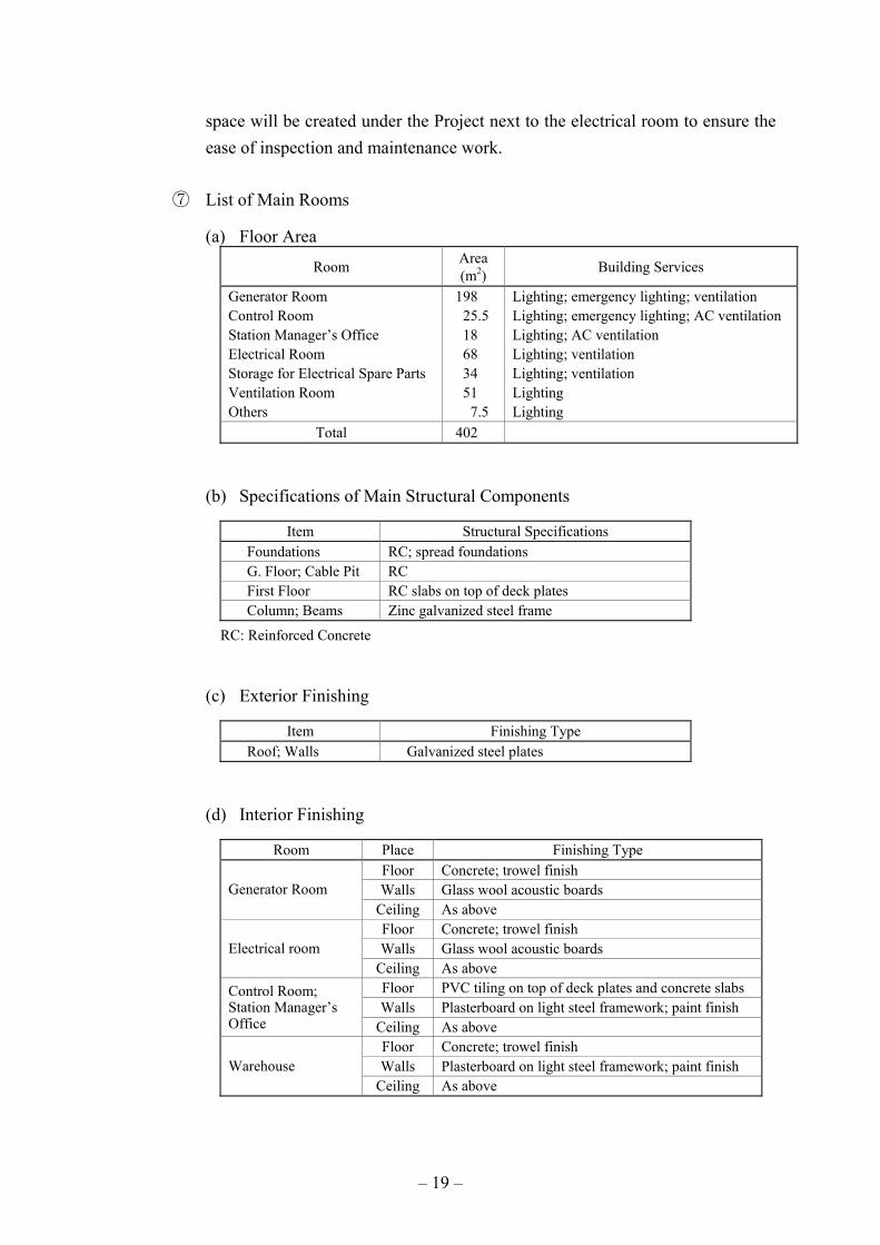
⑦ List of Main Rooms
(a) Floor Area
Room Area (m2) Building Services
Generator Room Control Room Station Manager’s Office Electrical Room Storage for Electrical Spare Parts Ventilation Room Others
198 25.5 18 68 34 51
7.5
Lighting; emergency lighting; ventilation Lighting; emergency lighting; AC ventilation Lighting; AC ventilation Lighting; ventilation Lighting; ventilation Lighting Lighting
Total 402
(b) Specifications of Main Structural Components
Item Structural Specifications Foundations RC; spread foundations G. Floor; Cable Pit RC First Floor RC slabs on top of deck plates Column; Beams Zinc galvanized steel frame
RC: Reinforced Concrete
(c) Exterior Finishing
Item Finishing Type Roof; Walls Galvanized steel plates
(d) Interior Finishing
Room Place Finishing Type Floor Concrete; trowel finish Walls Glass wool acoustic boards Generator Room
Ceiling As above Floor Concrete; trowel finish Walls Glass wool acoustic boards Electrical room
Ceiling As above Floor PVC tiling on top of deck plates and concrete slabs Walls Plasterboard on light steel framework; paint finish
Control Room; Station Manager’s Office Ceiling As above
Floor Concrete; trowel finish Walls Plasterboard on light steel framework; paint finish Warehouse
Ceiling As above

– 20 –
4) Cross-Section Plan
The cross-section of the new generator room will be the same as that of the existing generator rooms. The ceiling height will be approximately 10 m in consideration of (i) the required height to hoist a component (cylinder) using the three ton crane installed in the ceiling and (ii) the height of the generator of approximately 4 m.
5) Structural Plan
① Main Structure of Building
The main structure will be a steel-frame structure which is the same as that employed by the existing building. The employment of this type of structure will shorten the construction period and reduce the building weight, reducing the burden on the foundations. A new construction method using the expansion technique will be used for the extended building as the welding method to weld the new section to the existing building is judged to be inappropriate because of (i) the low level of welding skill by local workers and (ii) the need to minimize adverse impacts on the existing powerhouse during the period of the extension work. Zinc plating will be applied to the steel surface to prevent salt contamination.
② Foundation Type
The ground for the power station consists of elevated coral reef, providing good support for the powerhouse and equipment foundation. Accordingly, spread foundations will be used.
③ Re-Use of Existing Structural and Finishing Materials
While it will be necessary to remove the structural steels and finishing materials on the existing wall where the planned extension will be constructed, re-use of these materials will be planned as much as possible.
6) Building Equipment
The building services equipment for the main rooms will be basically the same as those installed under the previous project and are explained below.
① Fire Extinguishing System
One ABC fire extinguisher (6 kg type) each will be provided in the generator room, station manager’s office, electrical room, control room and warehouse. In

– 21 –
the case of the generator room, two 20ℓ type fire extinguishers on wheels will be provided because of the presence of many combustible materials, including fuel oil and lubricating oil. A smoke detector will be installed in rooms which are not constantly occupied and the fire alarm panel installed under the previous project will be remodelled. A fire alarm will be displayed on the existing control panel.
② Lighting and Receptacles
JIS standards will be used as the standards for the indoor luminous intensity and lighting will, in principle, be provided by either fluorescent lamps or mercury lamps. Meanwhile, mercury lamps will be used for outdoor lighting as in the case of the existing outdoor lamps.
③ Air-Conditioning
For the control room and station manager’s room, packaged type air-conditioners will be provided. The existing air-conditioning units will be re-used by distributing them in accordance with the room layout after extension and the minimum required remodelling work will be conducted.
④ Ventilation
A forced air suction system using a blower will be employed in the generator room to feed combustion air to the diesel engine and to ventilate the generator room. In the case of other main rooms, mechanical ventilation using a fan or natural ventilation using louvers, etc. will be considered. The air velocity at the air intake port for the blower will be not greater than 2.5 m/s. This intake port will be structured to prevent the invasion of rainwater at the time of blower operation and will be given an air filter to prevent the unwanted entry of insects, etc. into the generator room. The density of this filter will gradually increase from the inflow side to the outflow side to reduce the pressure loss. The filter unit will be a panel unit which the filter can be re-used after washing and easily replaced.
⑤ Rainwater Collection and Feeding System
The rainwater to be used in the powerhouse for drinking and miscellaneous purposes will be collected from the roof of the building and stored in a ground water tank (1×5 m3) for pumped feeding to the water treatment facility. The new water tank will be placed near the water tank installed under the previous project and both tanks will be connected by a pipe.

– 22 –
Table 2-2-2 Outline of Rainwater Collection System
Equipment Procurement Quantity Specifications
Rainwater Collection System - Rainwater Storage Tank
1
Outdoor-type (reinforced plastic); capacity: 5 m3
⑥ Crane
For the Project, the overhead three ton crane installed under the previous project will be used by extending the rail to the extended generator room.
⑦ Remodeling of Existing Facilities
Some of the existing facilities will be remodeled and relocated under the Project to ensure the planning of economical building service with good maintainability. Those facilities which have to be remodeled for their effective use are listed in Table 2-2-3.
Table 2-2-3 Existing Facilities Requiring Remodeling
Facility Description of Necessary Remodeling Fire Detection and Alarm System
1) Remodeling of the fire alarm panel (additional detector and alarm) 2) Addition of fire detectors (electrical room and electrical component warehouse) 3) Exit lights
Air-Conditioning and Ventilation System
1) Relocation of the air-conditioning unit in the control room 2) Relocation of the ventilation system in the electrical room
Lighting and Plug Socket System
1) Extra lighting in the generator room 2) Extra lighting in the electrical room 3) Extra lighting in the control room 4) Extra indoor emergency lighting 5) Extra outdoor lighting
Telephone System 1) Additional interphone in the station manager’s office 2) Additional interphone in the electrical room 3) Additional interphone in the electrical component warehouse
7) Foundations
Foundations will be constructed for the diesel engine generators, auxiliary machinery, electrical equipment and oil tanks, etc. Pits for the plumbing and cables will also be constructed.

– 23 –
(4) Generating Facility Plan (Procurement and Installation)
While the main generating equipment will be installed inside the powerhouse, sufficient prevention measures against salt contamination should be taken for some of the auxiliary equipment to be installed outdoors. The necessary facility for the construction of the new generating unit will, therefore, be selected based on the following basic requirements and conditions.
1) Basic Requirements
① Generating Method
The diesel engine generator will be selected in consideration of the existing power station in Kiribati and the easy operation and maintenance of such power station.
② Control Method
A control room will be established on the first floor of the powerhouse to conduct remote control operation as same as the existing generating units. The starting up and stopping of the diesel engine will, however, be done at locally (by the engine) for safe operation.
③ Fuel Composition
The fuel currently used by the existing Bikenibeu Power Station is diesel oil, which is imported from Singapore. The use of the same diesel oil for the new generating unit is planned and the composition of this diesel oil is shown in Table 2-2-4.
Table 2-2-4 Composition of Diesel Fuel Oil
Item Unit Testing Method Value / Composition
Flash Point Kinetic Viscosity (50°C) Pouring Point Residual Carbon Moisture Content Ash Content Sulphur Content Density
°C mm2/s °C
mass % mass ppmmass % mass % g/cm3
JIS K2265 (PM method) JIS K2283 JIS K2269 JIS K2270 JIS K2275 (Carl Fischer method) JIS 2272 JIS 2541 JIS K2249
67.0 2.420 -2.5
≦0.01 332
≦0.01 0.80
0.8423
Source: Basic Design Study Team

– 24 –
④ Composition of Lubricating Oil
Although the composition of lubricating oil may slightly vary from one generator manufacturer to another, lubricating oil with the same specifications as those for that currently used (Mobile No.312) will be used for the new generating units for compatibility with the existing units and minimization of the storage space.
⑤ Cooling Water
The cooling water to be used for the new generating unit will be water treated by the water softener installed under the previous project. The capacity of the cooling water tank will be the same as that of the existing tanks and will be sufficiently large enough to fill one inspected radiator with cooling water in a single operation. An anti-corrosion agent will be mixed with the water to prevent internal corrosion. In addition, two years’ supply of ion exchange resin which is used for the existing water softener will be provided under the Project. Meanwhile, one rainwater tank will be newly installed for the efficient use of rainwater and the existing tank will be remodelled to allow the supply of cooling water from both tanks.
2) Planning Concept
① Engine Output and Generator Capacity
The rated engine generator output required for the Project will be decided based on the following conditions.
(a) The target year of the Project will be 2011, i.e. five years after completion of the Project (end of 2005).
(b) The generating capacity should be decided to ensure positive power balance in the target year (2011).
(c) Arrangements should be made to allow the stoppage of the new generator for inspection and maintenance purposes.
(d) The minimum annual operating hours will be 8,000 hours based on continuous operation (base load operation).

– 25 –
In consideration of the above conditions, the optimal generator capacity will be 1,400kW and one generator will be required as described in the power supply and demand forecast (see 2.2.2-(1)-3)).
The required engine output and the rated capacity of the generator are calculated below. As the engine specifications vary from one manufacturer to another, the following specifications will be used for general guidance purposes only.
• Engine Output
PS115,27355.0
PPeG
=η×
≥
Where, Pe : engine output (PS) P : output at generator terminal (1,400 kW) ηG : efficiency of generator (assumed to be 90%)
• Generator Capacity
kVA750,1PfPPG ==
Where, PG : generator capacity (kVA) P : output at generator terminal (1,400 kW) Pf : power factor (0.8, lagging)
Table 2-2-5 Engine Output and Generator Capacity
Item Output/Capacity
Engine Output Pe (PS) 2,115 Generator Capacity PG (kVA) 1,750
② Examination of Engine Speed
When diesel generators with a single unit capacity of 1,400kW are used to meet the base load, it is a common practice for Japanese power companies to use medium speed diesel generators of 750 rpm or lower in consideration of economical operation and maintenance. The operation performance of such

– 26 –
diesel generators up to the present has been very favorable. The revolving speed of all existing generators in Kiribati is 750 rpm. Taking the composition of the lubricating oil to be used into consideration, an engine speed of 750 rpm or lower will be selected for the Project.
③ Planning of Auxiliary Mechanical Systems
Common equipment system will be used as much as possible for the auxiliary mechanical systems to ensure easy operation, maintenance, energy conservation and a low cost of procurement. These systems are outlined below.
(a) Fuel Supply System
i) Fuel Tank
Considering the capacity of the new generating unit to be installed under the Project, one fuel tank will be installed outdoors because of the reasons explained in ii) below. Fuel unloading system installed under the previous project to unload fuel oil to the fuel tanks will be used by remodeling the existing piping to connect them to the new fuel tank. For the supply of fuel oil to the new diesel engine, the existing system will be used in a similar manner. As the fuel oil may contain water and/or foreign materials, a floating suction in each tank will recover only the separated fuel oil for its supply to the diesel engines. The separated foreign materials resulting from sedimentation will be combusted in the incinerator installed under the previous project.
ii) Tank Capacity
The tank capacity is determined based on the fuel consumption volume of the generating unit in 2011, the target year of the Project, and taking the diesel oil storage capacity of the KOIL described below into proper consideration in view of the selection of a sufficient capacity to prevent any interruption of the power supply due to a fuel shortage.
- Storage Capacity of KOIL
The maximum diesel oil storage capacity of the KOIL in 2003 is 1,300 m3. Two power stations of the PUB consume 400 m3/month with vehicles, boats and privately-owned emergency generators consuming the remaining quantity. Meanwhile, Mobile Oil supplies
– 27 –
the KOIL with an amount of diesel oil to reflect the consumption volume every four weeks.
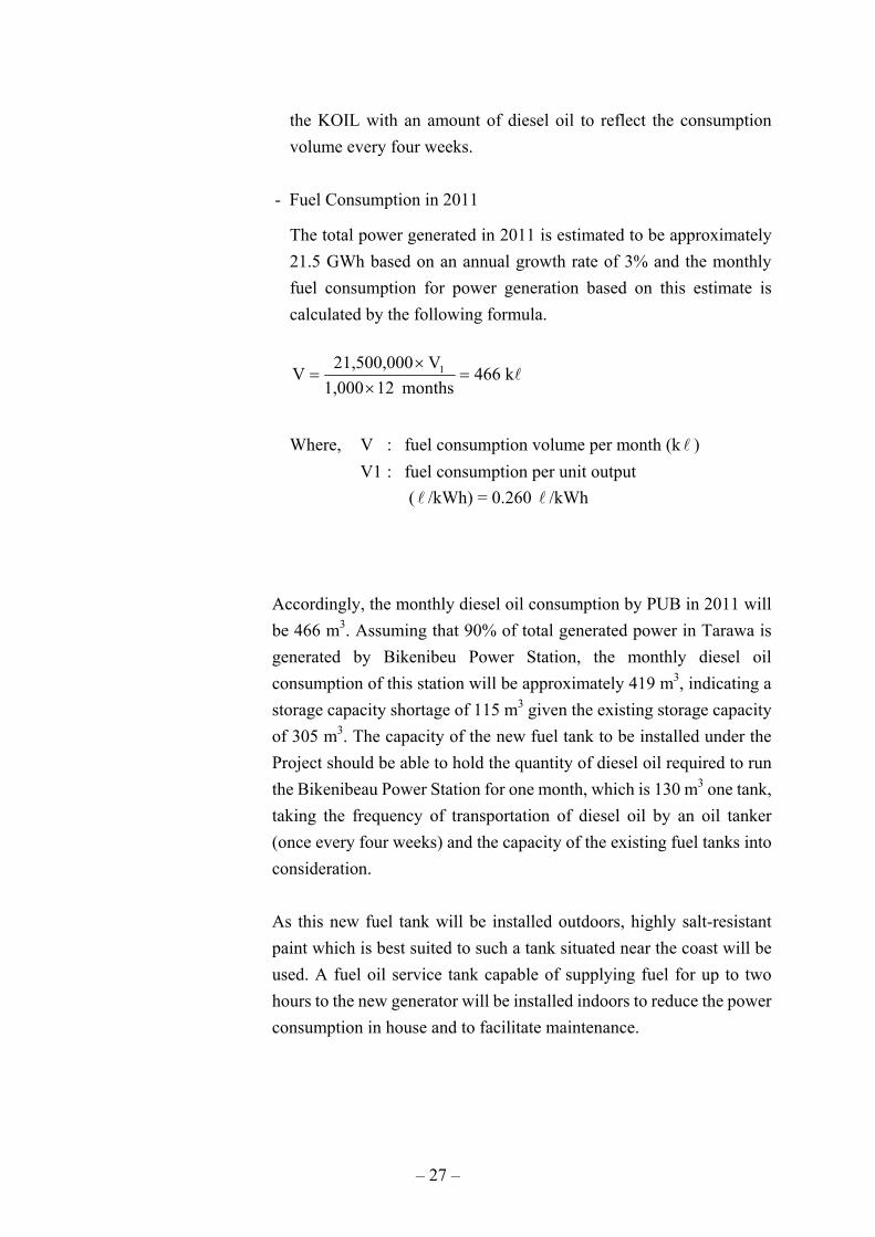
- Fuel Consumption in 2011
The total power generated in 2011 is estimated to be approximately 21.5 GWh based on an annual growth rate of 3% and the monthly fuel consumption for power generation based on this estimate is calculated by the following formula.
lk466months121,000
V21,500,000V 1 =×
×=
Where, V : fuel consumption volume per month (k l ) V1 : fuel consumption per unit output ( l /kWh) = 0.260 l /kWh
Accordingly, the monthly diesel oil consumption by PUB in 2011 will be 466 m3. Assuming that 90% of total generated power in Tarawa is generated by Bikenibeu Power Station, the monthly diesel oil consumption of this station will be approximately 419 m3, indicating a storage capacity shortage of 115 m3 given the existing storage capacity of 305 m3. The capacity of the new fuel tank to be installed under the Project should be able to hold the quantity of diesel oil required to run the Bikenibeau Power Station for one month, which is 130 m3 one tank, taking the frequency of transportation of diesel oil by an oil tanker (once every four weeks) and the capacity of the existing fuel tanks into consideration.
As this new fuel tank will be installed outdoors, highly salt-resistant paint which is best suited to such a tank situated near the coast will be used. A fuel oil service tank capable of supplying fuel for up to two hours to the new generator will be installed indoors to reduce the power consumption in house and to facilitate maintenance.

– 28 –
(b) Lubricating Oil System
The new diesel engine will have a built-in lubricating oil tank. The lubricating oil will be changed every 8,000 hours of operation and filter oil cleaner will be installed to reduce the maintenance cost. The lubricating oil will be directly supplied to the tank from the drum using the manual pump provided under the previous project inside the powerhouse. The lubricating oil system diagramme is shown in Basic Design Drawing TB-M203.
(c) Cooling Water System
As it is difficult to secure continuous water supply on the site, a closed circulation system using a radiator will be adopted to reduce the water consumption as in the case of the existing generating units. Cooling water treated by the existing water softener will be used to avoid any adverse impacts on the radiator. The cooling water tank installed under the previous project will be used to supply cooling water for the radiator of No.5 unit and jacket water expansion tank branched from the outgoing pipe of existing pressurizing pump unit. The cooling water system diagramme is shown in Basic Design Drawing TB-M204.
(d) Start-Up System
The start-up system for the diesel engine will be a pneumatic start-up system using compressed air as in the case of the previous project because of its advantage of gaining a large start-up torque. The existing compression system can be started by either a motor or an engine and will be used for the new diesel engine. Under the Project, the outlet piping of the existing compression system will be remodelled for connection to the new air receiver which will have a sufficient capacity to start the engine three times as in the existing case. The high humidity level of the local air means that water will tend to accumulate in the air receiver. An automatic water discharge valve which works periodically will, therefore, be installed to the air receiver. The compressed air system diagramme is shown in Basic Design Drawing TB-M205.
(e) Intake Air and Exhaust Gas System
This system for the supply of combustion air and for indoor ventilation will be installed inside the powerhouse. Exhaust air from the engine will be discharged to the outside via an outdoor silencer. The system capacity will

– 29 –
be sufficient to allow the rated operation of the new generating unit. The air intake and exhaust gas system flow diagramme is shown in Basic Design Drawing TB-M206.
(f) Sludge Treatment System
The Bikenibeu Power Station has an oil separation tank and a sludge disposal system which were installed under the previous project. As these have a sufficient capacity and have been intermittently used, they will be used for the Project with new piping connections being constructed to the existing oil separation tank where waste oil and water are separated. As only the separated water will be discharged, environmental pollution should be avoided. Existing incinerator will be untilized to dispose of the separated sludge and waste oil in an appropriate manner. As most parts of the system will be installed outdoors, salt-resistant materials will be selected with an additional coating. The sludge disposal system diagramme is shown in Basic Design Drawing TB-M202.
(g) Piping
The piping under the Project consists of the piping for compressed air, cooling water, fuel oil and drain. While the pipes will be laid in trenches or with supports inside the powerhouse for easy maintenance, outdoor pipes will be directly buried underground to ensure the maximum use of the available land. All of the buried pipes will receive such protection measures as anti-corrosive jute sheathing, etc. Each pipe will be color-coded for easy maintenance and to avoid miss-operation. During the construction period, temporary diversion of the fuel pipes will be required and the necessary pipes, etc. for this diversion will be procured under the Project.
④ Electrical Facility Plan
The main electrical facility to be installed is described below. The single line diagramme for the Bikenibeu Power Station is shown in Basic Design Drawing TB-E201.
(a) Generator
The new 3-phase, 3 wire method, alternating synchronous generator will have a horizontal shaft, air cooling system and salient or cylindrical pole type with removable perforated sheet metal for the cooling air, taking the
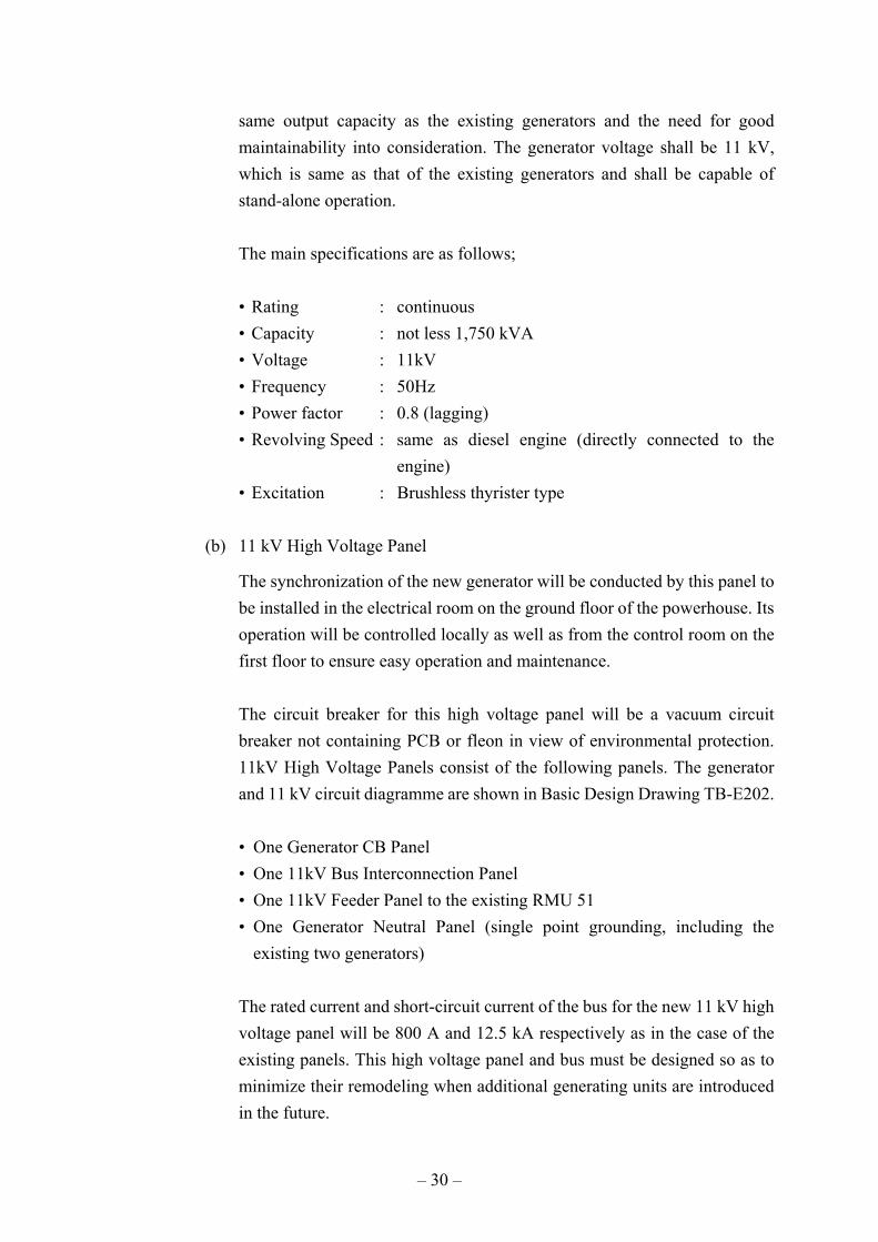
– 30 –
same output capacity as the existing generators and the need for good maintainability into consideration. The generator voltage shall be 11 kV, which is same as that of the existing generators and shall be capable of stand-alone operation.
The main specifications are as follows;
• Rating : continuous • Capacity : not less 1,750 kVA • Voltage : 11kV • Frequency : 50Hz • Power factor : 0.8 (lagging) • Revolving Speed : same as diesel engine (directly connected to the
engine) • Excitation : Brushless thyrister type
(b) 11 kV High Voltage Panel
The synchronization of the new generator will be conducted by this panel to be installed in the electrical room on the ground floor of the powerhouse. Its operation will be controlled locally as well as from the control room on the first floor to ensure easy operation and maintenance.
The circuit breaker for this high voltage panel will be a vacuum circuit breaker not containing PCB or fleon in view of environmental protection. 11kV High Voltage Panels consist of the following panels. The generator and 11 kV circuit diagramme are shown in Basic Design Drawing TB-E202.
• One Generator CB Panel • One 11kV Bus Interconnection Panel • One 11kV Feeder Panel to the existing RMU 51 • One Generator Neutral Panel (single point grounding, including the
existing two generators)
The rated current and short-circuit current of the bus for the new 11 kV high voltage panel will be 800 A and 12.5 kA respectively as in the case of the existing panels. This high voltage panel and bus must be designed so as to minimize their remodeling when additional generating units are introduced in the future.

– 31 –
(c) Low Voltage Distribution Panel
A 415 V low voltage distribution panel will be installed in the electrical room together with the 11 kV high voltage panel to supply power to the auxiliary equipment for the new generating unit, auxiliary systems and powerhouse. The single line diagramme for the 415 V low voltage circuit is shown in Basic Design Drawing TB-E203.
(d) Local Control Panel
A local control panel will be provided at the side of each engine to monitor the status of engine operation.
(e) DC Power Supply System
The existing 110 V DC power supply system will be used as the power source for the control panel and circuit breaker, etc. The existing DC power supply panel will be remodelled to secure the feeder for the Project.
(f) Grounding System
The required grounding system under the Project will consist of the following.
• Grounding to protect the ground fault (direct grounding system for both 11 kV and 415 V circuits as in the case of the existing system)
• Grounding to prevent electric shocks from metal surfaces or electrical equipment
• Grounding for the fuel oil tank (separate from the above two systems) • Grounding for the lightning rod (separate from the above three systems)
(g) Cable Installation
The same cable installation method used in the previous Project will be used for the Project. The cables inside the powerhouse will be placed inside a cable trench, tray or conduit while the cables outside the powerhouse will be either placed inside a conduit or directly buried underground. Those cables placed inside a cable trench or conduit will not be armored while those directly buried underground will have armor protection. Copper conductor cables will be used in view of its good flexibility and general-purpose cross-linked polyethylene will be used for insulation.

– 32 –
(h) Instruments
Given the fact that the instruments to be used for various types of equipment serve for public power supply, an accuracy class of JIS 1.0 will be adopted for such integrating instruments as watthour meters and fuel oil flow meters because of their direct link to the performance and economic operation of the equipment while an accuracy class of 1.5 or higher will be adopted for such indicators as ammeters, voltmeters and pressure gauges, etc. in view of their main purpose of checking the operating conditions.
3) Outline of Main Equipment
The outline of the specifications for the main equipment for the generating unit to be installed under the Project are shown in Table 2-2-6.

– 33 –
Table 2-2-6 Outline of Main Generating Equipment
Equipment Name Procurement Quantity Approximate Specifications
(1) DEG Unit 1) Diesel Engine
1
Duty : continuous operation Output : not less than 2,115 PS Revolving speed : not more than 750 rpm Type : four cycle Cooling system : radiator cooling Fuel oil : diesel oil with service tank With common base and anti-vibration system
2) Generator 1 Duty : continuous operation Rated output : 1,750 kVA Number of phases : three phase three wire Rated voltage : 11,000 V Revolving speed : not more than 750 rpm Power factor : 0.8 (lagging) Frequency : 50 Hz Coil connection : Y connection (direct grounded) Exciter : brushless thyrister type
3) Electrical Equipment ① Control Panel ② Protection Relay Panel ③ 11 kV High Voltage Panel ④ 415 V Low Voltage Panel ⑤ Materials for Remodeling of
Existing Systems
1 set 1 set
1 set 1 set
1
Desk-type; controls and monitors generating equipment Self standing-type for generator and 11 kV high voltage panels 11 kV, including vacuum circuit breaker 415 V, including MCCB For 11 kV and 415 V panels, control panel and protection relay panels
4) Mechanical Systems ① Fuel Supply System
a) Fuel Storage Tank
② Materials for Remodeling of Existing Systems
1
1 set
Type : vertical for outdoor installation Capacity : 130 m3/tank For fuel oil, lubricating oil, cooling water, compressed air and drain systems
(2) Spare Parts for DEG Units 1) Normal Operation (Consumables) 2) Emergency (Breakdown)
2 years supply
(16,000 hrs)
Oil filter elements, lubricating oil filter elements, o- rings, fuel injection nozzles and ion exchange resin for water softener, etc.
(3) Maintenance Tools for DEG Units 1 set Engine tools, valve seat grinder and others
(4) Repair Tools 1 set Mechanical work tool set, electrical work tool set, instrument tools and grounding tools, etc.
4) Remodeling of Existing Equipment and Systems
The Project plans the wide-range remodeling of the existing mechanical and electrical equipment/systems to effectively use the equipment/systems installed under the previous
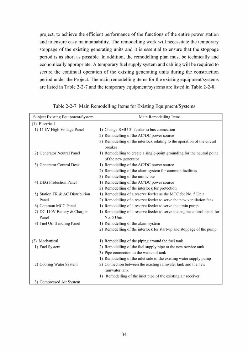
– 34 –
project, to achieve the efficient performance of the functions of the entire power station and to ensure easy maintainability. The remodelling work will necessitate the temporary stoppage of the existing generating units and it is essential to ensure that the stoppage period is as short as possible. In addition, the remodelling plan must be technically and economically appropriate. A temporary fuel supply system and cabling will be required to secure the continual operation of the existing generating units during the construction period under the Project. The main remodelling items for the existing equipment/systems are listed in Table 2-2-7 and the temporary equipment/systems are listed in Table 2-2-8.
Table 2-2-7 Main Remodelling Items for Existing Equipment/Systems
Subject Existing Equipment/System Main Remodelling Items (1) Electrical
1) 11 kV High Voltage Panel 2) Generator Neutral Panel 3) Generator Control Desk 4) DEG Protection Panel 5) Station TR & AC Distribution
Panel 6) Common MCC Panel 7) DC 110V Battery & Charger
Panel 8) Fuel Oil Handling Panel
(2) Mechanical 1) Fuel System 2) Cooling Water System 3) Compressed Air System
1) Change RMU 51 feeder to bus connection 2) Remodelling of the AC/DC power source 3) Remodelling of the interlock relating to the operation of the circuit
breaker 1) Remodelling to create a single-point grounding for the neutral point
of the new generator 1) Remodelling of the AC/DC power source 2) Remodelling of the alarm system for common facilities 3) Remodelling of the mimic bus 1) Remodelling of the AC/DC power source 2) Remodelling of the interlock for protection 1) Remodelling of a reserve feeder as the MCC for No. 5 Unit 2) Remodelling of a reserve feeder to serve the new ventilation fans 1) Remodelling of a reserve feeder to serve the drain pump 1) Remodelling of a reserve feeder to serve the engine control panel for
No. 5 Unit 1) Remodelling of the alarm system 2) Remodelling of the interlock for start-up and stoppage of the pump 1) Remodelling of the piping around the fuel tank 2) Remodelling of the fuel supply pipe to the new service tank 3) Pipe connection to the waste oil tank 1) Remodelling of the inlet side of the existing water supply pump 2) Connection between the existing rainwater tank and the new
rainwater tank 1) Remodelling of the inlet pipe of the existing air receiver

– 35 –
Table 2-2-8 Main Temporary Equipment/Systems
Subject Existing Equipment/Systems Main Remodelling Items
(1) Electrical 1) Power source to the radiator of No. 4 Unit 2) Interphone between the work site and the
existing old power station and new station 3) Grounding of the low voltage panel 4) Power source for the fuel transfer pump
control panel 5) Power source for outdoor lighting
(2) Mechanical 1) Main fuel pipe between the fuel transfer pump
and the new powerhouse
1) Installation of a power source and the control cable 2) Installation of the communication cable 3) Installation of the grounding wire 4) Installation of the power source and the control cable 5) Installation of the power cable
1) Installation of a temporary pipe
(5) Distribution Facility Plan (Procurement and Installation)
Under the Project, the Japanese side will also be responsible for the construction of 11kV distribution lines totaling approximately 18 km. The equipment and materials to be used for these lines will be selected based on the following conditions and the outline of the planned equipment. The 11 kV basic distribution network diagramme in South Tarawa is given in Basic Design Drawing TD-E201.
1) Basic Conditions
① Electrical System
The electrical system for the new and upgraded distribution lines will be the same as the existing system as described below.
a) High voltage distribution system : 11kV, three phase, three wires (maximum voltage: 12 kV)
b) Low voltage distribution system : 415 ~ 240 V, three phase, five wires (three phase +neutral line + grounding line)
c) Frequency : 50 Hz
d) Interrupting capacity : 11 kV system, 12.5 kA (1 sec. sym)
e) Grounding system : direct grounding
f) Basic insulation level (BIL) : 11 kV system; 95 kV, AC 38 kV
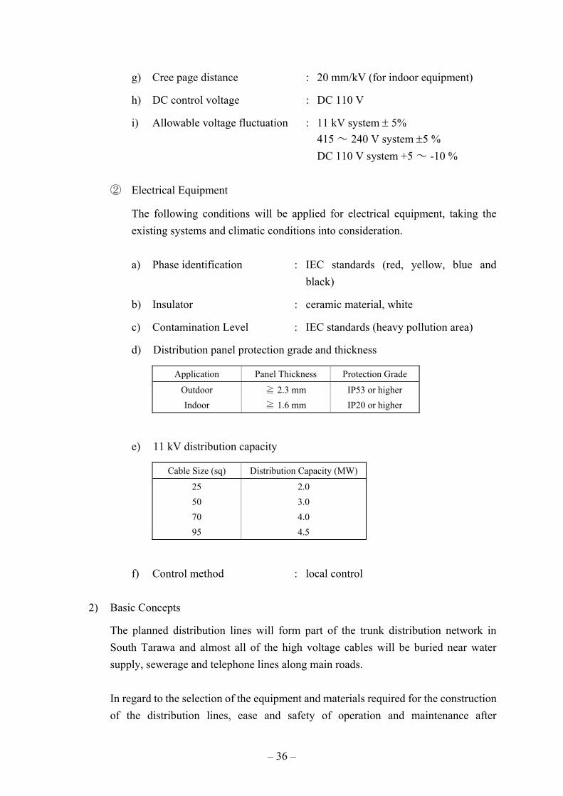
– 36 –
g) Cree page distance : 20 mm/kV (for indoor equipment)
h) DC control voltage : DC 110 V
i) Allowable voltage fluctuation : 11 kV system ± 5% 415 ~ 240 V system ±5 % DC 110 V system +5 ~ -10 %
② Electrical Equipment
The following conditions will be applied for electrical equipment, taking the existing systems and climatic conditions into consideration.
a) Phase identification : IEC standards (red, yellow, blue and black)
b) Insulator : ceramic material, white
c) Contamination Level : IEC standards (heavy pollution area)
d) Distribution panel protection grade and thickness
Application Panel Thickness Protection Grade
Outdoor Indoor
≧ 2.3 mm ≧ 1.6 mm
IP53 or higher IP20 or higher
e) 11 kV distribution capacity
Cable Size (sq) Distribution Capacity (MW)
25 50 70 95
2.0 3.0 4.0 4.5
f) Control method : local control
2) Basic Concepts
The planned distribution lines will form part of the trunk distribution network in South Tarawa and almost all of the high voltage cables will be buried near water supply, sewerage and telephone lines along main roads.
In regard to the selection of the equipment and materials required for the construction of the distribution lines, ease and safety of operation and maintenance after

– 37 –
completion of the construction work should be carefully taken into consideration. The equipment installation period is planned to be as short as possible to minimize power interruption and disruption to traffic during the work period.
Given the fact that the distribution equipment to be newly installed under the Project will be located near private houses and/or general structures, the distribution equipment will be fenced with a common grounding system for both electrical equipment and fence in order to ensure safety and to minimize any adverse impacts of faults caused by electrical equipment. The equipment design, etc. will incorporate adequate measures to prevent salt contamination in view of the vulnerability of the installation sites to salt damage.
The work to install upgraded cables will be planned taking the following matters into consideration.
• It will be necessary of routes for the new cables to be those for the existing cables because of the limited land availability.
• It will be necessary for the work period to be as short as possible to minimise any adverse impacts on lives of local residents to the blockage of traffic, etc.
• It will be necessary to complete the work to remove the existing high voltage cables as efficiently and quickly as possible.
3) Distribution Substations
The planned distribution substations will step down 11 kV high voltage to 415 – 240 V low voltage and each substation will consist of a ring main unit, an 11 kV / 415 – 240 V transformer. These substations will have outdoor specifications and will, in principle, be located at the sites of existing substations where existing equipment will be removed. In the case of the new substations, government-owned plot will be used to avoid any problems related to land ownership and each substation will be installed within 9 m of the centre of the existing road.
The transformer capacity of T31 to be upgraded under the Project will be 100 kVA, i.e. the same as that of the existing substation, in consideration of the current load situation. The circuit configuration of the new ring main unit, considering easy maintenance, will be the same as that of the existing one, consisting of load break switches for incoming and outgoing lines and a disconnecting switch with fuse for the distribution transformer. As PUB is familiar with the operation and maintenance of

– 38 –
the ring main unit manufactured by BS Standard, BS or similar will be used as the standards for the ring main unit to be used under the Project. Moreover, for the prevention of salt contamination, the charged element will be sealed together with the use of highly salt-resistant paint and materials.
4) High Voltage Circuit Breaker Panel
The high voltage circuit breaker panel to be procured under the Project plays the important functions of ensuring the proper operation of the distribution lines and of protecting them. One panel will be installed at Betio under the Project because the existing panel is already ont of operation. This panel will be given a synchronizer to interconnect Betio Area with the Bikenibeu Power Station. Instruments capable of measuring voltage, current, watts and effective power as in the case of existing instruments will be provided.
5) High Voltage Cables
All of high voltage cables to upgrade the existing cables or for new installation will be 11 kV cables and will be directly buried underground. Because of the limited land availability, replaced cable routes will be the same as existing routes. New routes will, in principle, run within 9 m of the center of the road as in the case of existing routes.
The cable size will be sufficient to maintain power distribution to consumers at an allowable voltage drop, when the Betio Power Station is stopped in the target year of the Project. Three core copper conductor cross linked polyethylene insulated power cable (XLPE) with wire armored will be employed in view of workability and durability.
All of the termination material will be indoor-type and will be same as the existing one to ensure compatibility of spare parts.
Most of cable junction boxes used for the existing ring main units are old type which use a compound insulation material. Because of their poor workability and maintainability, they are hardly used at present and are difficult to procure. For the connection of the cables under the Project, cold shrinkable type insulation material offering excellent workability and maintainability will be used to shorten the work period.
The size and length of the high voltage cables based on the above conditions are given below.

– 39 –
Cable Laying Section Cable Size (mm2) Cable Length (m)
1. Upgrading of Existing Lines 1) Existing RMU 13 – New RMU 63 2) New RMU 63 – Betio Area 3) Existing RMU 31 – New RMU 64 4) Existing RMU 13 – Existing RMU 18 - Existing RMU 13 – Existing Transformer (T13) - Existing RMU 31 – Existing Transformer (T31)
95 70 50 25 - -
4,860 7,590 3,560
490 - -
2. Construction of New Lines 1) Existing RMU 39 – New RMU 64
25
1,050
All of the distribution lines subject to be upgraded under the Project are currently in operation. In order to minimize any adverse impacts by the implementation work for the existing underground cables on consumers by reducing the frequency and duration of power outage, the work will be simultaneously conducted at several sites to ensure stable power supply.
The new cables procured under the Project will be laid after completion of excavation at each site. The existing cables will be removed after switching over to the new cables, followed by backfilling and other necessary work. It will be necessary for a series of work, i.e. excavation, removal of the existing cables, laying of the new cables and backfilling, to be continuously conducted for safety and shortening of the work period. Therefore removal of the existing cables will be conducted by Japanese side. The trunk 11 kV cables and cables crossing a road will be installed in conduits to shorten the period of traffic disruption as much as possible in order to minimise any adverse impacts on local people.
7) Low Voltage Distribution Lines
The installation for 415/240 V low voltage distribution lines to be connected to consumers will be the responsibility of the Kiribati side and, therefore, are not included in the scope of the Project.
8) Inspection and Maintenance
At the time of the periodic inspection or emergency by fault, etc., it will be necessary to take the distribution equipment to be procured under the Project to PUB Workshop for inspection. During this period, replacement equipment must be temporarily installed to continue power supply to consumers. This series of work must be quickly carried out to minimise the duration of a power interruption. For this reason, a crane

– 40 –
truck will be required. However, PUB currently does not have such a truck because of financial constraints. One truck equipped with a crane will, therefore, be procured under the Project to meet the minimum requirements for inspection and maintenance. This truck will be a four-wheel drive type because of its need to travel on sandy ground or uneven roads. The main specifications of the truck are described below.
a) Equipped with a three ton crane
b) Loading capacity: four tons
c) Boom length: approximately 11 m
d) Radius of gyration of the boom: approximately 10 m
e) Four-wheel drive
9) Outline of Main Distribution Equipment
The main distribution equipment to be procured under the Project is listed in Table 2-2-9.
Table 2-2-9 Outline of Main Distribution Equipment
Equipment Name Procurement Quantity Specifications
1. Distribution Substation - Ring Main Unit - Distribution Transformer - Substation Wiring Materials
4 sets
1 4 sets
Outdoor-type, self-standing, 11 kV Outdoor-type, 11 kV/415 – 240 V, 100 kVA 11 kV cable (between RMU and Tr), grounding materials, fencing materials and accessories
2. Circuit Breaker Panel 1 Outdoor-type, self-standing, Vacuum or SF6 insulated, 11 kV, 630 A, 12.5kA (1 sec)
3. High Voltage Cable - For Upgraded Line - For New Line
4,860 m 7,590 m 3,560 m 490 m
1,050 m
11 kV, copper conductor, three core, 95 mm2, wire armoured 11 kV, copper conductor, three core, 70 mm2, wire armoured 11 kV, copper conductor, three core, 50 mm2, wire armoured 11 kV, copper conductor, three core, 25 mm2, wire armoured 11 kV, copper conductor, three core, 25 mm2, wire armoured
4. Spare Parts - For Normal Operation - For Emergency Operation
For 2 years 1 set 1 set
Fuses and lamps, etc.
5. Maintenance Tools 1 set Cable jack, volt meter, ammeter and insulation resistance tester, etc.
6. Crane truck for Maintenance Work
1 set Three ton crane, 4WD and boom length of approximately 11 m

– 41 –
10) Distribution Network Diagramme
The distribution network incorporating the distribution equipment to be installed under the Project is shown in Basic Design Drawing TD-E201. The analysis results on the power flow and voltage drop after upgrading the system are described in Appendix 6. This analysis was conducted using the following presumptions to simplify the results.
a) Demand factor for distribution transformer: 100%
b) Output of the Betio Power Station: 1,850 kW
2.2.3 Basic Design Drawings
The following basic design drawings have been prepared for the Project.
< Power Station Construction Plan >
TB-G201 General Arrangement of Bikenibeu Power Station
TB-G202 Bikenibeu P/S Arrangement of Generating Facility
TB-E201 Key Single Line Diagram of Bikenibeu Power Station
TB-E202 Single Line Diagram for 11 kV System
TB-E203 Single Line Diagram for Low Voltage System
TB-M201 Key Flow Diagram
TB-M202 Fuel Oil & Sludge Treatment System Flow Diagram
TB-M203 Lubrication System Flow Diagram
TB-M204 Cooling Water System Flow Diagram
TB-M205 Compressed Air System Flow Diagram
TB-M206 Air Intake & Exhaust Gas System Flow Diagram
TB-A201 Finishing and Doors & Windows Schedules of the Powerhouse
TB-A202 Plan of Powerhouse
TB-A203 Elevation of Powerhouse
< Distribution Network Upgrading Plan >
TD-G200 11 kV Distribution Route Map in Tarawa

– 42 –
TD-G201 11 kV Distribution Route Map (1/4) Betio – Bairiki Area
TD-G202 11 kV Distribution Route Map (2/4) Bairiki – Ambo Area
TD-G203 11 kV Distribution Route Map (3/4) Ambo – Bangantebure Area
TD-G204 11 kV Distribution Route Map (4/4) Bangantebure – Bonriki Area
TD-G211 Layout of 11kV Circuit Breaker Panel (C/B1) and Ring Main Unit (RMU63)
TD-G212 Layout of Ring Main Unit (RMU31) and 11kV Distribution Transformer (T31)
TD-G213 Layout of 11kV Ring Main Unit (RMU13)
TD-G214 Layout of 11kV Ring Main Unit (RMU64)
TD-E201 11 kV Distribution System
TD-E202 Single Line Diagram of 11kV Distribution Facility (CB & RMU)

Title
BIKENIBEU POWER STATION
GENERAL ARRANGEMENT OFTB-G201
DWG. No

BIKENIBE
ARRANGEMENT OF GENERATING FACILITY
Title
TB-G202
DWG. No


