baseplate kit it installation instructions … your base-plate has removable arms, they must be...
TRANSCRIPT
KIT# 524432-101/25/18
KSR
O
A
D
M
A
S
T
E
R,
I
N
C.
ROADMASTER, Inc. 6110 NE 127th Ave. Vancouver, WA 98682 360-896-0407 fax 360-735-9300 www.roadmasterinc.com
BASEPLATE KIT INSTALLATION INSTRUCTIONS
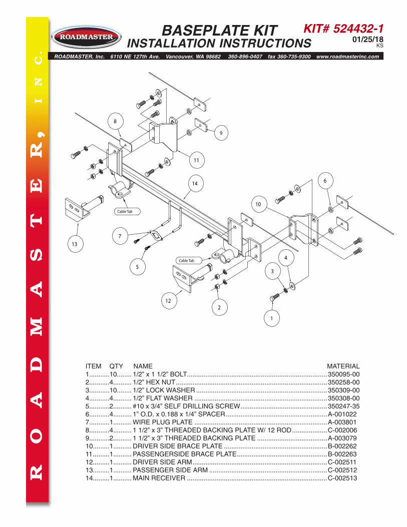
ITEM QTY NAME MATERIAL1...........10........ 1/2” x 1 1/2” BOLT ............................................................................350095-002...........4.......... 1/2” HEX NUT ..................................................................................350258-003...........10........ 1/2” LOCK WASHER .......................................................................350309-004...........4.......... 1/2” FLAT WASHER ........................................................................350308-005...........2.......... #10 x 3/4” SELF DRILLING SCREW ...............................................350247-356...........4.......... 1” O.D. x 0.188 x 1/4” SPACER .......................................................A-0010227...........1.......... WIRE PLUG PLATE ........................................................................A-0038018...........4.......... 1 1/2” x 3” THREADED BACKING PLATE W/ 12 ROD ...................C-0020069...........2.......... 1 1/2” x 3” THREADED BACKING PLATE ......................................A-00307910.........1.......... DRIVER SIDE BRACE PLATE ........................................................B-00226211 .........1.......... PASSENGERSIDE BRACE PLATE .................................................B-00226312.........1.......... DRIVER SIDE ARM .........................................................................C-00251113.........1.......... PASSENGER SIDE ARM ................................................................C-00251214.........1.......... MAIN RECEIVER ............................................................................C-002513
1
2
4
5
6
7
10
11
8
12
13
14
Cable Tab
Cable Tab
3
9
KIT# 524432-101/25/18
KS
Fig.A
Fig.B
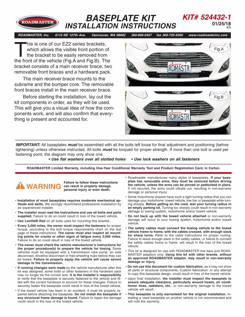
This is one of our EZ2 series brackets, which allows the visible front portion of the bracket to be easily removed from
the front of the vehicle (Fig.A and Fig.B). The bracket consists of a main receiver brace, two removable front braces and a hardware pack. The main receiver brace mounts to the subrame and the bumper core. The removable front braces install in the main receiver brace. Before starting the installation, lay out the kit components in order, as they will be used. This will give you a visual idea of how the com-ponents work, and will also confirm that every-thing is present and accounted for.
BASEPLATE KIT INSTALLATION INSTRUCTIONS
ROADMASTER, Inc. 6110 NE 127th Ave. Vancouver, WA 98682 360-896-0407 fax 360-735-9300 www.roadmasterinc.com
IMPORTANT: All baseplates must be assembled with all the bolts left loose for final adjustment and positioning (before tightening) unless otherwise instructed. All bolts must be torqued for proper strength. If more than one bolt is used per fastening point, the diagram may only show one.
• Use flat washers over all slotted holes • Use lock washers on all fasteners
• Installation of most baseplates requires moderate mechanical ap-titude and skills. We strongly recommend professional installation by an experienced installer.
• The installer must read the instructions and use all bolts and parts supplied. Failure to do so could result in loss of the towed vehicle.
• Use Loctite® Red on all bolts used for mounting this bracket.
• Every 3,000 miles, the owner must inspect the fasteners for proper torque, according to the bolt torque requirements chart on the last page of these instructions. The owner must also inspect all mount-ing points for cracks or other signs of fatigue every 3,000 miles. Failure to do so could result in loss of the towed vehicle.
• The owner must check the vehicle manufacturer's instructions for the proper procedure(s) to prepare the vehicle for towing. Some vehicles must be equipped with a transmission lube pump, an axle disconnect, driveline disconnect or free-wheeling hubs before they can be towed. Failure to properly equip the vehicle will cause severe damage to the transmission.
• If running changes were made by the vehicle manufacturer after this kit was designed, some bolts or other fasteners in the hardware pack may no longer be the correct size. It is the installer’s responsibility to verify that the baseplate is securely fastened to the vehicle and fit-ted with the correct hardware to account for these changes. Failure to securely fasten the baseplate could result in loss of the towed vehicle.
• If the towed vehicle has been in an accident, it must be properly re-paired before attaching the baseplate. Do not install the baseplate if any structural frame damage is found. Failure to repair the damage could result in the loss of the towed vehicle.
ROADMASTER Limited Warranty, including One-Year Conditional Warranty Text and Product Registration Card, in Carton.
• Roadmaster manufactures many styles of baseplates. If your base-plate has removable arms, they must be removed before driving the vehicle, unless the arms can be pinned or padlocked in place. If not secured, the arms could vibrate out, resulting in non-warranty damage or personal injury.
• Some motorhome chassis have such a tight turning radius that you can damage your motorhome, towed vehicle, tow bar or baseplate while turn-ing sharply. Before getting on the road, test your turning radius in an empty parking lot. Turning too sharply could result in non-warranty damage to towing system, motorhome and/or towed vehicle.
• Do not back up with the towed vehicle attached or non-warranty damage will occur to your towing system, motorhome and/or towed vehicle.
• The safety cables must connect the towing vehicle to the towed vehicle frame to frame, with the cables crossed, with enough slack for sharp turns. Refer to the cable instructions for proper routing. Failure to leave enough slack in the safety cables, or failure to connect the safety cables frame to frame, will result in the loss of the towed vehicle.
• This kit is designed for use with ROADMASTER tow bars and ROAD-MASTER adaptors only. Using this kit with other brands, without an approved ROADMASTER adaptor, may result in non-warranty damage or injury.
• Do not use this document for custom fabrication, as it may not show all parts or structural components. Custom fabrication, or any attempt to copy this baseplate design, could result in loss of the towed vehicle.
• Upon final installation, the installer must inspect the baseplate to ensure adequate clearance, particularly around hoses, air condi-tioner lines, radiators, etc., or non-warranty damage to the towed vehicle will result.
• This baseplate is only warranteed for the original installation. In-stalling a used baseplate on another vehicle is not recommended and will void the warranty.
Failure to follow these instructions can result in property damage, personal injury or even death.WARNING

KIT# 524432-101/25/18
KS
Fig.C Fig.D
Fig.E Fig.F
Fig.G
BASEPLATE KIT INSTALLATION INSTRUCTIONS
ROADMASTER, Inc. 6110 NE 127th Ave. Vancouver, WA 98682 360-896-0407 fax 360-735-9300 www.roadmasterinc.com
1. Important: please use all supplied bolts and parts and read all instructions carefully before beginning this installation. The majority of questions you may have can be answered within the text, and proper installation will ensure safe and secure travel. Now, begin the installation. Remove four plastic fasteners attaching the radiator cover to the upper grille (Fig.C).
2. Pull back the upper grille to locate four clips attaching the upper grille to the fascia (Fig.D — driver's side).
3. Working from one side to the other, carefully pull the upper grille away from the fascia and slide a screwdriver under the upper grille to push down to release each of the four clips you located in step 2 (Fig.E and Fig.F). Remove the upper grille from the fascia.
4. Use a screwdriver to release five clips attaching the fascia to the fascia support (Fig.F — passenger side).
5. On each side, remove one plastic fastener and two T30 screws attaching the corner of the fascia to the fender liner (Fig.G).
All illustrations and specifications contained herein are based on the latest information available at the time of publication approval. ROADMASTER, INC. reserves the right to make changes at any time without notice in material, specification and models or to discontinue models.

KIT# 524432-101/25/18
KS
Fig.H Fig.I
Fig.J
BASEPLATE KIT INSTALLATION INSTRUCTIONS
ROADMASTER, Inc. 6110 NE 127th Ave. Vancouver, WA 98682 360-896-0407 fax 360-735-9300 www.roadmasterinc.com
6. On each side, remove three plastic fasteners attaching the fascia to the splash shield (Fig.H — driver's side).
7. Pull out and forward to release the fascia from its locking strip (Fig.I). There are two large clips holding the fascia to the vehicle under each headlight. Use a large flathead screwdriver to release each one. Disconnect the fascia sensors and fog lights, if the vehicle is so equipped, and remove the fascia.
8. Disconnect the sensor wiring loom from the bottom of the shock absorption pad.
9. Using the yellow lines in Figure J as a reference, cut off the shock absorption pad. The dashed lines indicate cuts behind the protruding air snorkus.
Fig.K
10. Cut off the support tab on the driver's side (Fig.K) and remove an 8mm (head) bolt attaching the plastic bracket to the core support (Fig.L).
Fig.L

KIT# 524432-101/25/18
KS
Fig.M Fig.N
BASEPLATE KIT INSTALLATION INSTRUCTIONS
ROADMASTER, Inc. 6110 NE 127th Ave. Vancouver, WA 98682 360-896-0407 fax 360-735-9300 www.roadmasterinc.com
11. On the passenger side, bend the horn bracket up and then temporarily remove the horns by removing one 10mm (head) bolt (Fig.M).
12. On each side, drill out the two pre-existing holes in the subframe using a ½" drill bit (Fig.N).
Fig.O Fig.P
Fig.Q
13. On each side, insert one of the supplied 3/16" x 1½" x 3" threaded backing plates without rod into the bottom of the subframe (Fig.O). Arrange the hardware for the rear support plate for each side as shown in Figure P, with the ½" x 1½" bolt, ½" lock washer, ½" flat washer, and finish with the 1" O.D. x ¼" x .188 wall pipe spacer and loosely bolt into the threaded backing plate in the bottom hole of the subframe.
Now, place one of the supplied 1" O.D. x ¼" x .188 wall pipe spacers between the upper mount of the rear support plate (Fig.Q). Ensure the pipe spacer (yellow arrow) is temporarily held in place between the plate and the upper mount-ing hole by tightening the lower bolt (Fig.R).
Fig.R

KIT# 524432-101/25/18
KS
BASEPLATE KIT INSTALLATION INSTRUCTIONS
ROADMASTER, Inc. 6110 NE 127th Ave. Vancouver, WA 98682 360-896-0407 fax 360-735-9300 www.roadmasterinc.com
Fig.S Fig.T
Fig.U
14. On each side, insert one of the 3/16" x 1½" x 3" threaded backing plates with rod in the bottom of the subframe, aligning it with the holes in the upper mounting hole the rear support plate. Now, using the supplied ½" x 1½" bolt, ½ flat washer and ½" lock washer, bolt through the upper mounting hole of the rear support plate, pipe spacer, upper mounting hole in the subframe and into the threaded backing plate with rod (Fig.S).
Fig.W
15. Working on one side at a time, place one of the supplied 3/16" x 1½" x 3" threaded backing plates with rod inside the bumper core, aligning it with the pre-existing holes in the bumper core and bending the rod as necessary (Fig.T). Using a second person to help hold the bracket, lift the bracket under the bumper core and align the holes in the main receiver brace with the pre-existing holes in the face of the bumper core.
Fig.V
Now, using the supplied ½" x 1½" bolts and ½" lock washers, bolt through the main receiver brace, bumper core and into the threaded backing plate with rod (Fig.U). Note: ensure proper alignment, as the bolts will receive Loctite® Red and will be torqued at the end of these in-structions.
16. On the passenger side, pull the washer bottle neck up through the engine compartment to remove it (Fig.V). Now, remove two 10mm (head) bolts attaching the washer bottle to the subframe (Fig.W). Let it hang down for now. Note: due to manufacturing variances, some vehicles may not be equipped with the washer bottle in this particular spot. If that is the case, proceed to the next step to finish the installation.

KIT# 524432-101/25/18
KS
BASEPLATE KIT INSTALLATION INSTRUCTIONS
ROADMASTER, Inc. 6110 NE 127th Ave. Vancouver, WA 98682 360-896-0407 fax 360-735-9300 www.roadmasterinc.com
Fig.Z
23. Insert the removable front bracket arms into the front receiver braces, and twist each one 90 degrees to lock.
24. Install the tow bar to the mounting bracket according to the manufacturer's instructions.
IMPORTANT!
Safety cables are required by law. When towing, connect safety cables to the safety cable tabs illustrated on page 1. Make certain there is adequate slack in the cables to allow a full turning radius; otherwise, damage will result. If necessary, longer cables or cable extensions are available.
Note: if the bracket is so equipped, the holes in the alignment tabs which are welded to the arms and main receiver braces are for padlocks only. Under no circumstances should you bolt the alignment tabs together. Bolting the alignment tabs together may result in non-warranty damage to the bracket.
Fig.Y
All illustrations and specifications contained herein are based on the latest information available at the time of publication approval. ROADMASTER, INC. reserves the right to make changes at any time without notice in material, specification and models or to discontinue models.
17. Tighten the bolts to the bolt torque requirements found at the end of these instructions.
18. Replace the washer bottle, reversing step 16.
19. Reinstall the horns using the 10mm (head) bolt you removed in step 11. Bend the horn bracket to make certain it does not contact the mounting bracket.
20. Remove the duct shroud on the back side of the fascia (Fig.X). It will not be replaced. Note: retain the duct shroud in case the mounting bracket is ever removed.
21. Reference the yellow arrow and lines in Figure Y to trim off the tab and to trim the fascia on both sides. Figure Z shows the completed trimming.
22. Reinstall the fascia, reversing steps 1 through 7.
Fig.X
KIT# 524432-101/25/18
KS
Fig.AA
All illustrations and specifications contained herein are based on the latest information available at the time of publication approval. ROADMASTER, INC. reserves the right to make changes at any time without notice in material, specification and models or to discontinue models.
BASEPLATE KIT INSTALLATION INSTRUCTIONS
ROADMASTER, Inc. 6110 NE 127th Ave. Vancouver, WA 98682 360-896-0407 fax 360-735-9300 www.roadmasterinc.com
BOLT TORQUE REQUIREMENTS
METRIC BOLTSThread Size Grade Torque12mm-1.25 ...........8.8 ............. 64 ft./lb. 12mm-1.5 .............8.8 ............. 60 ft./lb.12mm-1.75 ...........8.8 ............. 55 ft./lb.14mm-2.0 .............8.8 ............. 88 ft./lb.
METRIC BOLTSThread Size Grade Torque6mm-1.0 ............8.8 .............6 ft./lb. 8mm-1.0 ............8.8 ...........18 ft./lb. 8mm-1.25 ..........8.8 ...........16 ft./lb.10mm-1.25 ........8.8 .......... 36 ft./lb.10mm-1.5 ..........8.8 .......... 31 ft./lb.
STANDARD BOLTSThread Size Grade Torque5/16-18 ............5 ................ 13 ft./lb. 3/8-16 ..............5 ................ 23 ft./lb.7/16-14 ............5 ................37 ft./lb.1/2-13 ..............5 ................57 ft./lb.5/8-11 ...............5 .............. 112 ft./lb.
Note: The torque values represented below are intended as general guidelines. Torque requirements for specific applications may vary. Roadmaster does not warrant this information to be accurate for all applications and disclaims all liability for any claims or damages which may result from its use.
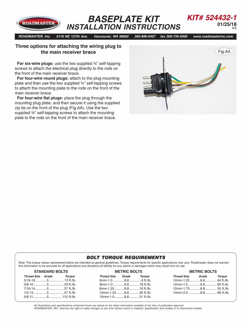
Three options for attaching the wiring plug to the main receiver brace
For six-wire plugs: use the two supplied ¾” self-tapping screws to attach the electrical plug directly to the rods on the front of the main receiver brace. For four-wire round plugs: attach to the plug mounting plate and then use the two supplied ¾” self-tapping screws to attach the mounting plate to the rods on the front of the main receiver brace. For four-wire flat plugs: place the plug through the mounting plug plate, and then secure it using the supplied zip tie on the front of the plug (Fig.AA). Use the two supplied ¾” self-tapping screws to attach the mounting plate to the rods on the front of the main receiver brace.