barnstable community horace mann public school … no.2 … · neta ats-7.1 2. dry type...
TRANSCRIPT

RDK Engineers 200 Brickstone Square Andover, MA 01810-1488 April 9, 2010
BARNSTABLE COMMUNITY HORACE MANN PUBLIC SCHOOL HEATING AND VENTILATING SYSTEM REPLACEMENT
HYANNIS, MASSACHUSETTS
ADDENDUM NO. 2
Addendum Number 2 April 9, 2010 Page 1 of 10 NOTICE TO BIDDERS: This addendum is issued prior to receipt of bids and does hereby become part of the contract Documents, and in case of conflict, it shall supersede original plans and specifications. ITEM 1: CLARIFICATIONS
1. To clarify the requirements for the usage of wiremold:
A. Wiremold - May be used for low voltage control applications in classrooms, offices, cafeteria, gymnasium and corridor and similar areas where installed along masonry or concrete walls. Wiremold shall be provided in standard colors to match adjacent surfaces. .
ITEM 2: DRAWINGS
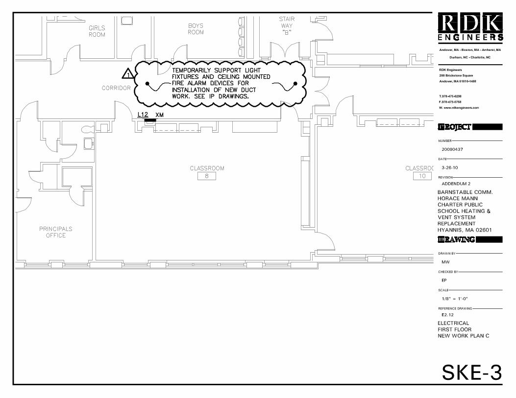
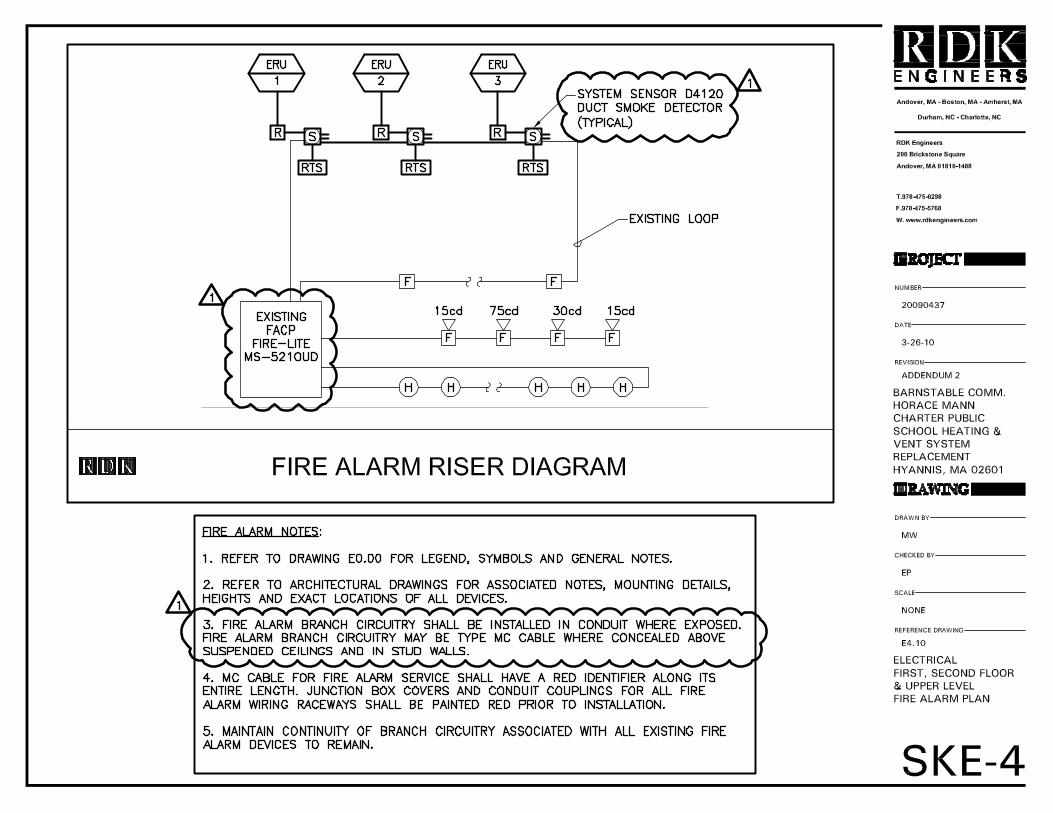
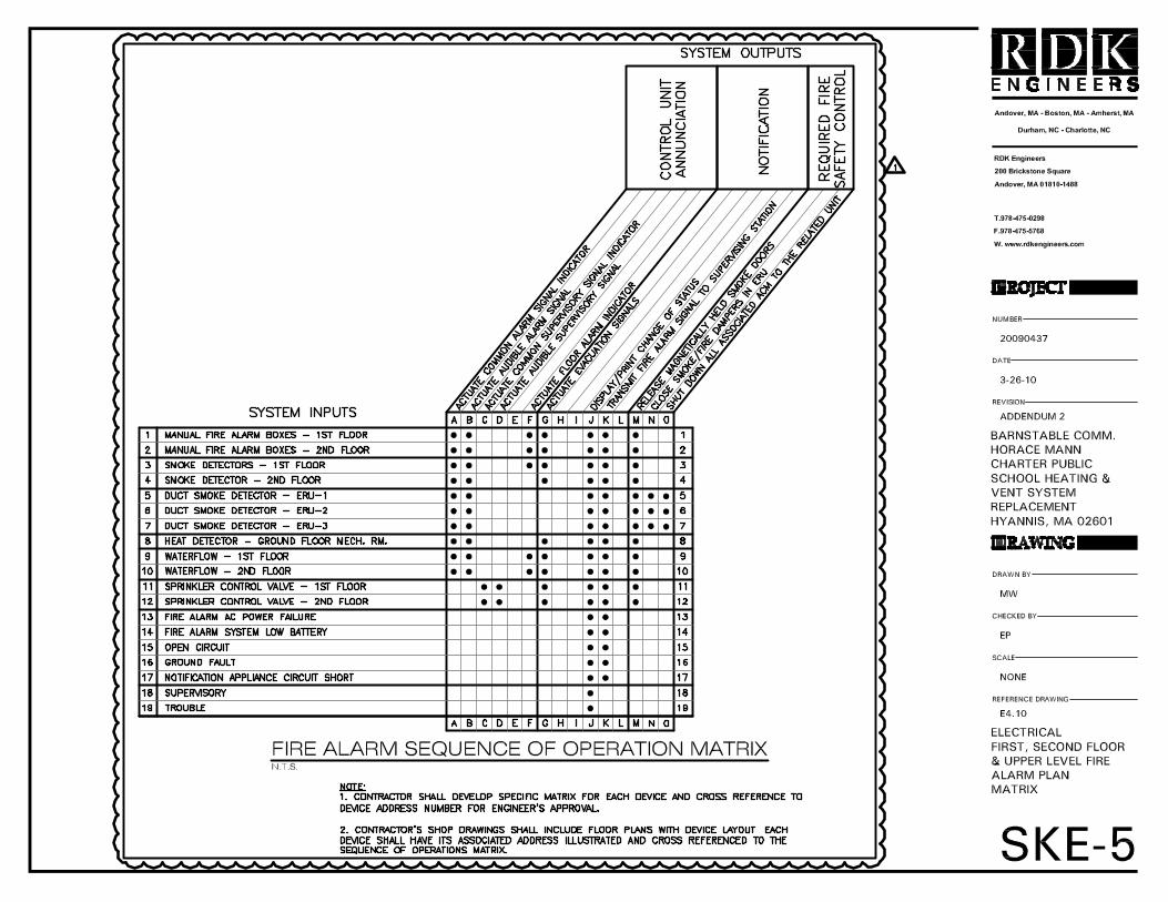
1. Refer to SKH-1 attached. Revised Boiler Schedule. 2. Add Electrical Sketches: SKE-1, SKE-2, SKE-3, SKE-4, SKE-5 and E9.0
ITEM 3: SPECIFICATIONS CHANGES Section 16000 Page ii - Delete the following: 2.04 WIRING DEVICES AND PLATES 2.11 FIRE ALARM-MODIFICATION TO EXISTING SYSTEM 3.04 WIRING DEVICES AND PLATES 3.10 FIRE ALARM Page 1 - On section 1.02 paragraph A, delete the following: “Lights will be required to be removed from the ceiling and reinstalled after the ceiling assembly has been re-installed.” Page 20 - On section 2.02 paragraph D, delete the following: “5. Provide water-tight gland sealing assemblies with pressure bushings equal to OZ/Gedney Type WSK for new cast-in-place installations or Type CSCM for retrofit (core drilling of existing walls) as required for below grade wall and floor penetrations.”
Page 21 - On section 2.03 paragraph E, delete the following: “3. Flexible Armored (AC) cable shall be UL Listed with THHN insulated conductors with an insulated grounding conductor within a galvanized steel interlocked armor with bare bond wire. Aluminum armor is not acceptable. Connectors shall be self-grommetted with lock nut connection to the termination point enclosure.”

RDK Engineers 200 Brickstone Square Andover, MA 01810-1488 April 9, 2010 On section 2.03 paragraph delete paragraph H Arc-proofing
Delete 2.04 WIRING DEVICES AND PLATES
Page 23 - On section 2.05 delete the following: paragraph H
Page 30, 31, 32, 33 – Delete 2.11 FIRE ALARM-MODIFICATION TO EXISTING SYSTEM
Page 38 Delete paragraph E Polyvinyl Chloride (PVC) Non-metallic Conduit
Page 39 Delete paragraph F
Delete paragraph G part 2
Delete paragraph H part 1 and 2
Page 40 Delete paragraph F part 2 and replace with “Flexible Armored (AC) cable may not be used in concealed locations for branch circuit wiring systems wiring only.”
Page 41 Delete paragraph H
Page 41 Delete 3.04 WIRING DEVICES AND PLATES
Page 43,44,45,46 Delete 3.10 FIRE ALARM
Page 47 On section 3.11 FIRE ALARM section A delete 4
Page 48 On section 3.11 FIRE ALARM section A part 8 delete f.
Page 51, 52, 53 Replace 3.13 ACCEPTANCE TESTS with the following:
3.13 BASIC ACCEPTANCE TESTS
A. General Scope
1. This section covers the required field tests and inspections to assess the suitability for initial energization of electrical power distribution equipment and systems. Failed components shall be replaced and retested for no additional cost to the project.
2. The purpose of this specification is to assure that all tested electrical equipment and systems are operational and within applicable standards and manufacturer’s tolerances and that the equipment and systems are installed in accordance with design specifications.
3. All testing shall be performed by the contractor responsible for the installation of the systems or by an independent testing organization under contract with the contractor.
4. All equipment utilized for testing shall have a valid calibration sticker. All test reports shall indicate the equipment utilized and its associated calibration due date.
5. Coordinate all required shutdowns with the owner. Any and all testing required after the owner has taken occupancy (temporary or permanent) shall be assumed to be conducted during premium time.
RDK Engineers 200 Brickstone Square Andover, MA 01810-1488 April 9, 2010
6. A written record of all tests and a final report summarizing the findings shall be submitted for approval prior to energizing any electrical power distribution equipment and systems. All equipment shall be left in clean operational condition.
B. Inspection and Test Procedures
The following tests shall be conducted using the noted section of the latest edition of NETA ATS Acceptance Testing Specifications for Electrical Power Distribution Equipment Systems as a reference:
1. Switchboard and Panelboard Assemblies – Visually inspect the equipment inside and out, check attachment to wall or floor, verify bus joint tightness, exercise all active components and perform continuity testing and megger phase to phase, neutral and ground. Minimum resistance shall be 100 megohms when 480V equipment tested at 1000VDC or 25 megohms when 208V equipment tested at 500VDC. Tabulate readings for each test. NETA ATS-7.1
2. Dry Type Transformers – Visually inspect the transformer inside and out, verify vibration isolation installation, verify installation of the grounding bonding jumper, verify termination joint tightness, measure no load and partially loaded voltage and adjust taps as necessary. NETA ATS-7.2
3. Low Voltage Cables - All feeders illustrated on the one line diagram shall be inspected and tested in accordance with the referenced standard. Visually inspect cables for physical damage, color code and proper termination. Check continuity for proper labeling and megger for insulation resistance. Megger test voltage shall be 1000VDC for 1 minute with no values less than 50 megohms. Tabulate readings for each feeder. NETA ATS-7.3
4. Low Voltage, Molded and Insulated Case Circuit Breakers with frame size greater than 225 amperes and/or with adjustable trip units shall be tested and adjustable settings dialed to match the coordination study criteria. Perform an insulation resistance test at 1000VDC (thermal magnetic) or 500VDC (solid state) for 1 minute from pole to pole and pole to ground, resistance values shall not be less than 100 megohms. Perform resistance test across open and closed breaker contacts of each phase. Test trip settings tolerance with primary current injection. Tabulate readings for each breaker. NETA ATS-7.6
5. Disconnect the main bonding jumper at the service and at each separately derived system and verify single connection between the grounded and grounding conductor. Reconnect all disconnected bonding connections. Test the grounding electrode system for resistance to earth to verify a maximum of 25 ohms. NETA ATS-7.13