(balke et al)tail rotor design part ii structural dynamics.pdf
TRANSCRIPT
8/10/2019 (Balke et al)Tail Rotor Design Part II Structural Dynamics.pdf
http://slidepdf.com/reader/full/balke-et-altail-rotor-design-part-ii-structural-dynamicspdf 1/15
Tail Rotor esign
Part II
Structural ynamics
R W. Balke
Assistant Dynamics Group Engineer
R.
L.
Bennett
PhD, Aeromechanics Engineer
T. M. Gaffey
Group Engineer VTOL Dynamics
R.
R. Lynn
Chief of Research and Development
Bell Helicopter Company
Fort Worth, Texas
In this Part
I
of
Tail Rotor Design, the structural dynamics
of stif f inplane tail rotor configurations are considered. First, the
placement of blade natural
frequencies
the method of calcula-
tion and the interaction between the natural frequencies and the
forcing functions are discussed in detail. Specific design guide-
lines are presented for two, three, and four blade rotors.
Second, the theoretical structural loading of a tail rotor is
treated and comparisons of theory and test results are given.
Finally, several aeroelastic phenomena associated with tail
rotors are discussed, including tail wagging, flut ter and di-
vergence, and blade motion stability. Throughout the text, spe-
cific problems which have been encountered are noted.
NOTATION
see Pa rt for notations not given here)
b tip-path-plane lateral flapping
CF
centrifugal forc e
Ip flapping inertia
mac mean aerodynamic chord
n
an integer
R rotor radius
V helicopter forw ard speed
flapping angle
AL perturbation lift
@ perturbation flapping angle
A@ perturbation pitch change
a
pitch-flap coupling angle, positive if pitch is
decreased when the b lade flaps up
advance ratio,
V aR
Presented at the 25th Annual National Forum of the American
Helicopter Society, May
1 9.
p
air density
aR
rotor ti p speed
a
main rotor rpm
a tail rotor rpm
w
fixed system excitation frequency
w
natur al frequency in th e rotating system
w
fundamental drive system natura l frequency
woo
static feathering natural frequency
NATURAL FREQUENCIES
FORMANY YEARS,
it was considered acceptable tail
rotor design practice merely to avoid the coincidence
of blade natural frequencies with rotor excitation fre-
quencies within th e flight oper ating regimes. Because of
the inadequacies of this approach in explaining the
overall behavior of a tail rotor, it was necessary to en-
gage in lengthy and expensive test programs to insure
the integrity of the hardware. Recent studies have
shown th at in addition to the aerodynamic excitahion
frequencies the effects
of
the main rotor , ta i l rotor
mounting, and transient loading must be considered
in defining th e proper frequency placement. Also these
items must he considered when interpreting test data.
With these items considered in the initial design stage
futur e development should be less costly an d tim e con-
suming.
I n the ensuing discussions, the term harmo nic is used
to denote frequencies which are integer multiples of
the ta il rotor rotational speed. The term nonharmonic
relates t o th e noninteger frequencies.
8/10/2019 (Balke et al)Tail Rotor Design Part II Structural Dynamics.pdf
http://slidepdf.com/reader/full/balke-et-altail-rotor-design-part-ii-structural-dynamicspdf 2/15
7
OCTOBER 1970 T A I L ROTOR DESIGN PAn l :
STRUCTURAL DYNAMICS
17
Uppel Frequency Lim it
Based on a review of flight data taken during tlic
development of the UH-1 and other Bell Helicopter
Co. helicopters, i t has been found th at oscillatory struc-
tur al loading of th e tail rotor is no t significant a t fre-
quencies greater than 150 Hz. This corresponds to 5
per rev for the UH-1 tail rotor. Since the upper fre-
quency limit will vary depending on tail rotor diameter
and n umb er of blades, it is suggested a nd bclieved t o be
conservative th at the per rev limit of be used in future
tail mtor blade design. Bell s tudies indicate that i t is
generally ade qua te to considcr only th e first four lower
modes of the tail rotor. Th is is somewhat less th an t he
5 per rev or the 150 cps l imit.
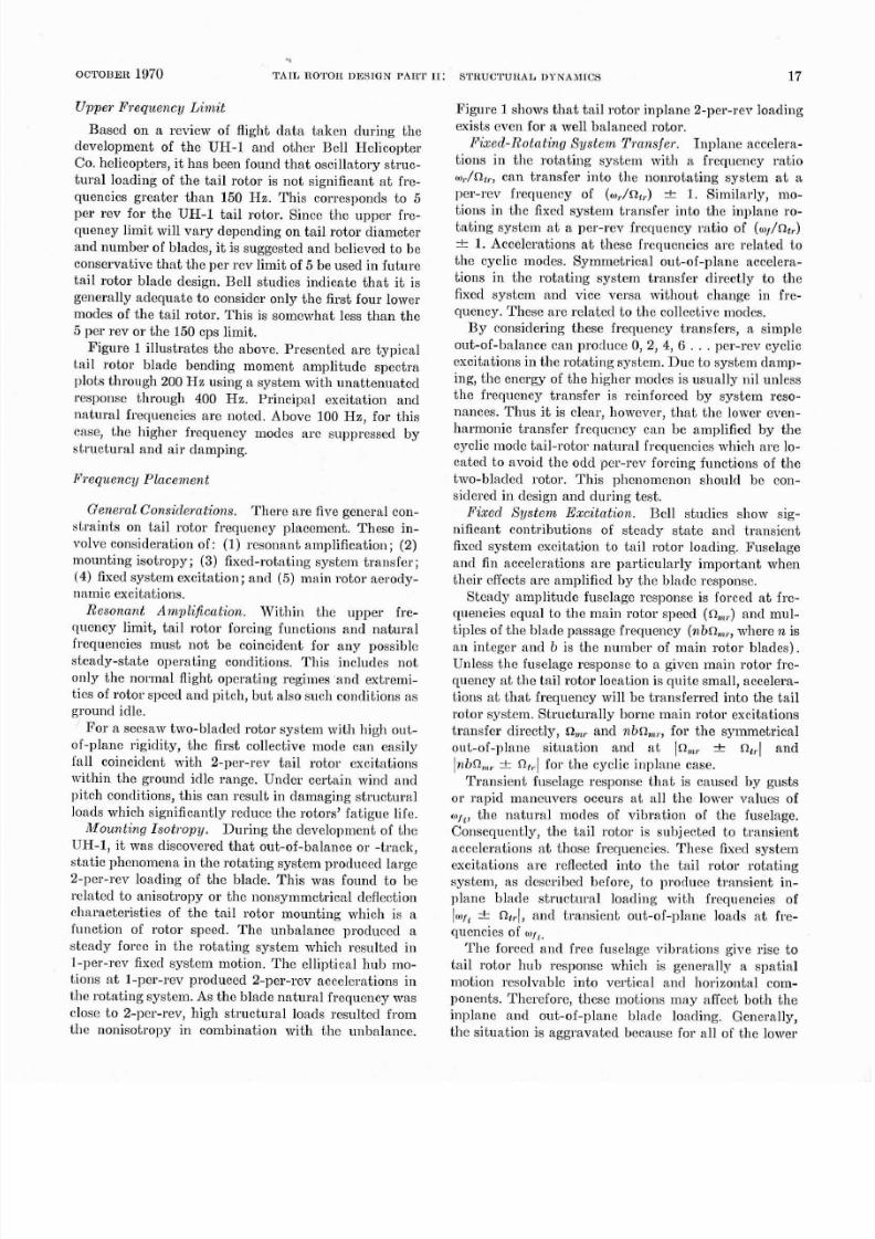
Figure l lustrates the above. Presented ar e typical
tail rotor blade bending moment amplitude spectra
11lots thr ou gh 200 1-12 using a system with unattenu ated
response througli 400 Hz. Principal excitation and
natu ral frequencies are noted. Above 100 Hz, for this
case, the higher frequency modes are suppressed by
structural and air damping.
Aeque ncy Placelnent
General Considerations.
The re are five gencral con-
straints on tail rotor frequency placement. These in-
volve consideration of: (1) resonant amplification; (2)
mounting isotropy; 3) fixed-rotating system tr ansfe r;
(4) f ixed system excitation; and (5) main rotor aerody-
nam ic excitations.
Reson ant Amplification. W ~t lii n th e upper fre-
quency limit, tail rotor forcing functions and natural
frequencies must not be coincident for any possiblc
steady-state operating conditions. This includes not
only the normal flight operating regimes and extremi-
ties of rotor spced and pitch, b ut also such conditions a s
ground idle.
For a seesaw two-bladed rotor system with high out-
of-plane rigidity, the first collective mode can easily
fal l coincident with 2-per-rev tail rotor excitations
within the ground idle range. Under certain wind and
pitch conditions, this can result in damaging struc tural
loads which significantly reduce the rotors fatigu e life.
Mounting Isotropy. Du rin g the development of the
UH-1, it was discovered th at out-of-balance or -track,
static phenomena in the rotating system produced large
2-per-rev loading of the blade. This was found to be
rclated to anisotropy or th e nonsymm etrical deflection
cliaracteristics of the tail rotor mounting which is a
func tion of rotor speed. T he unbala nce produced a
steady forcc in the rotating system which resnltcd in
1-per-rev fixed system motion. The elliptical hub mo-
tions at 1-per-rev produced 2-per-rev accelerations in
the rotating system. As the blade na tural frcquency was
close t o 2-per-rev, high struc tur al loads resulted from
the nonisotropy in combination with the m~balance.
Figure shows th at tail rotor inplane 2-per-rev loading
exists cvcn for a w ell balance d rotor.
Fixed-R otating System Transfer. Inpla ne accelera-
tions in t l ie rotating system with a frequency ratio
o,./ntr, can trans fer into th e nonrota ting system a t a
per-rev frequency of W ,
.
Similarly, mo-
tions in t l ie f ixed system transfer into the inplane ro-
tati ng system a t a per-rev frcquenc y ratio of (o,/Ot,)
=k 1.Accelerations a t these frequencics a re related t o
the cyclic modes. Symmetrical out-of-plane accelera-
t ions in the rotat ing sys tem t ransfer di rect ly to the
fixed system and vice versa without change in fre-
quency. These are related t o t he collective modes.
By considering these freqnency transfers, a simple
out-of-balan ce can procluce 0, 2, 4, 6 per-rev cyclic
excitations in the rotating system. Du e to system dam p-
ing, th e energy of th e higher modes is usually nil unless
tlie frequency transfer is reinforced by system reso-
nances. Th us it is clear, homever, th a t th e louver even-
harmonic transfer frequency can be amplified by the
cyclic mode tail-rotor na tu ra l frequencies which ar e lo-
cated t o avoid t he odcl pcr-rev forcing functions of tlie
two-bladccl rotor. This phcnomcnon should bc con-
sidered in design and during test.
Fized System Excitation. Bell s tudies show sig-
nificant contributions of stead y sta te and transient
fixccl system excitation to tail rotor loading. Fuselage
and fin accelcrations are particularly important when
their effectsare amplified b y the h ladc response.
Stea dy am plitude fuselage response is forced a t fre-
quencies equal to the m ain rotor speed n,,) and mnl-
tiples of th e blade passngc freq uency (nbn,,,,, w here n is
an integer and b is the number of main rotor blades).
Unless tlie fuselage responsc to a given main rotor fre-
quency a t he tail rotor location is qnite small, accelera-
tions a t th at frequency will be transferred into th e tail
ro tor system. S t l~ ~c tu ra l lyorne main rotor excitations
transfer directly,
om,
nd nbn,,,,, for the symmetrical
out-of-plane situa tion and a t in,,, n,,l and
InbCl,3,,
z
R,,I fo r th c cyclic inpla ne case.
Transient fuselage response that is caused by gusts
or rapid manenvers occurs at all the lourer values of
of the natu ral modes of vibration of the fuselage.
Consequently, the tail rotor is subjected to transient
accclcrations a t thos e frequencies. The se fixed system
excitations are reflected into the tail rotor rotating
system, as described before, to produce transient in-
plane blade structural loading with frequencies of
Jot, .
nt,J,
nd transient out-of-plane loacls a t fre-
quencies of
w
The forced and free fuselage vibrations give rise to
tail rotor hub response which is generally a spatial
motion resolvable into vertical and horizontal com-
ponents. Therefore, thcse motions m ay affcct both th e
inplanc and out-of-plane bladc loading. Generally,
the situ ation is agg rava ted because for a11 of t h e lower
8/10/2019 (Balke et al)Tail Rotor Design Part II Structural Dynamics.pdf
http://slidepdf.com/reader/full/balke-et-altail-rotor-design-part-ii-structural-dynamicspdf 3/15
..
R A LK E , B E N N E W , G A F F E S A N D IdYNS
JOURNAL O F THE ABIEIIICAN H ELICOPT ER SOCIETY
8
OUT OF PLANE AT 0 . 2 2 R ; 1 0 8 K NO TS L EV EL F L I G l l T
a .
2 7 . 5 1 1
2 4 0 j n = 3
b
OUT OF PLANE AT 0 .2 2R ; LEFT TURN ENTERED FROM 1 0 8 KNOTS: a,, 2 7 . 1 HZ
n=
1 2 0
1 S T OUT OF PLANE SYMMETRIC
2ND OUT OF PLANE SYMMETRIC
6 0 1 S T BEAM ASYMMETRIC 7
4 0
0 0
FREQUENCY - HZ
C
I N
P L A N E AT
0 . 0 5 ~ ; 108
KNOTS LEVEL
F L I G H T ;
n,,
2 7 . 5 H Z
4 0 0
n=
3 2 0
n=3
2 4 0
1
n=3
I
1 6 0
,
=
v
T 7
n = 1
m
n - 2
v
0
2 0 4 0 6 0 8 0 1 0 0 1 2 0 1 4 0 1 6 0 1 8 0 2 0 0
& FREQUENCY - HZ
t
d
IN PLANE AT 0 . 0 5 ~ : LEFT T U R N
E N T E R E D
FROM 1 0 8 K N O T S ;
ntr
2 7 . 1 H Z
C
2 4 0 =I
v
n.2
v
LST OUT OF PIANE ASYllMETRIC
n = 3
n= v
0 2 0 4 0 6 0 8 0 1 0 0 1 2 0 1 4 0 1 6 0 1 8 0 2 0 0
FREQUENCY HZ
FIGURE
Tail rotor
lndc
bending moment n~nplitudespectra l>lots for UH-1E helicaptcr

8/10/2019 (Balke et al)Tail Rotor Design Part II Structural Dynamics.pdf
http://slidepdf.com/reader/full/balke-et-altail-rotor-design-part-ii-structural-dynamicspdf 4/15
fuselage niorles, the tail ro tor is locatetl a t or nea r a n
antinode. Thus, s ignificant transient tail rotor hub
accclerations occur for essentially all fuselage natural
frequencies and significaut stead y am plitud e responses
occur for most main rotor excitations in the low-
frequency range. Since good design practice requires
placement of the fuselage natura l frequencies so as t o
avoid coinciclencc with the primary liiain rotor forcing
frequencies, tlie trans ient respouse occurs a t frequencics
between tlie n. and
? ~ b n , ~ , ,
xcitations.
With numerous natural frcquencics in close prox-
imity to the ta il rotor ro tationa l s1,eeds and higher
harmon ics, the possibility of beating phenom ena
should be considered. F or instance, drivc systcm , fusc-
lage and rotor flapping frequencies can interac t to pro-
duce non-harmonic beating. I some cases, beating
modcs can couple strongly, producing subharmonic
aeroe lastic problems such as tail wagging discussed
latcr. Otlier beating phenomena occur and dissipate a t
random , suggestive of gust distnrbances. This has little
implication with respect to structural dcsign other tha n
th at its recognition is necessary fo r ]~ossible ate r cor-
rective action.
Main Rotor Aerod?lnaoaic Excitations.
Figurc
1
shows the existcnce of main rotor I-, 2-, 4-, and 6-per-
rev frcquencies in tail-rotor loads during steady state
and maneuver flight. Also the data show the existcnce
of a ma in rotor 3-per-rev reflected in th e rotatin g sys-
tem. During maneuvers, the tail rotor out-of-plane
loads occurring a t main rotor 2-per-rev and the inplane
loads associatcd with the main rotor 3-per-rev are
most significant. Analytical studies discussed later
show most of these occurrences and indicate a cause to
be the main rotor wake a t the tail rotor location. The
relat ive contr ib~~t ionf tlie aerodynamic and fuselage
cffects is unknow n.
F ~ g n rc 0, in a later section, shows calculated tail
rotor spectra with and mithout main rotor wake in-
cluded. These main rotor aerodynamic effects shonld
be ack~iowlcd ged in ta il rotor design by avoiding
placement of tail rotor natural frecluencies coincident
with the first scveral main rotor liarmonics (n,,,,,
nbn,,,,,
Inn.,,
-c a,, ,and
\nhR,, n,,
for n
1
2, and 3).
Additional work is required to define the number of
harmonics that should be considered as a function of
~iu mb cr f main rotor blades, tail rotor location and
the per t inent tai l rotor parameters . In Ref . 1 , i t
is
noted t ha t high inplane stresses and low bladc life will
result due to aerod ynam ic effects if t he in plane nat ura l
frequency is located a t
bn,?,, n .
Th e UH-I series uses a noninteger gcar ratio bctween
the main and tail rotors. With a nonintegcr ratio, the
relative position of t he main and ta il rotor blades con-
tinuously changes, placing them in close proximity
about I/second. During many of the tests with this
machine unusual tail rotor loading lias been observed
as spikes in t l lc blade out-of-plane tra cc n~b ich ome-
times occur n'hen the blades are in closest proximity.
Th e loading varies from flight to flight and even during
the same flight, so a definite cause-effect relationship
has been elusive. The loading is important, howcver,
and mnst be includcd in the aircraft's fatigue spectrum.
Tlie phenomenon is presented h ere as a m atte r of record
and to alerl tcst and stluctures personncl to i ts ex-
istence.
F ~ e q z ~ e n c ulacenaent Design Guides.
Followillg are
the frcquency place ment guides developed for tlie gen-
era l case of tail roto r design.
A)
For conventional semi-rigid tail rotor design
and construction methods, all vibration modes occur-
ring bclow 150 H z should be considered.
(B) IIrit1iin this frequency limit, tail rotor n atu ral
frequcncies should not be coincident with nor in close
proximity to exciting force frequcncies for any steady
sta te operating conditions including ground idle specd.
(C) I n acldition to the tai l rotor per-rev frcquencies,
an attc mp t should he made to avoid na tural frequencies
coincident mith the excitation sources s l i o ~ nn Tablc I
for values of n and i of 1 and 2, a t least.
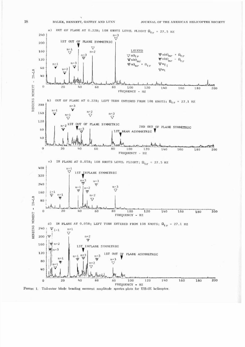
The above general rules are i l lustrated for a t~vo-
bladed rotor by Fig. 2.
Tes t Dn tn and C ompavisons.
For the tcst case
-shown by Fig. la a n d l o n 5.4 Hz, a,, = 27.5 Hz
and the principal main rotor induced vibrations art
given by n = 1, 2, 3, and 4. Based on these frequencies
and us ing Table I steady st ate tail rotor inplane bend-
ing
moments
a t frequen cies of 5.9, 16 .7, 22.1, 32.9, 38.3,
43.7, 49.1, 54.1, 59.9 and 70.7 Hz would he anticipated.
Similarly steady state out-of-plane moments at 5.4,
10.8,21.6,32.4, and 43.2
Hz
could b e expected.
Tlie turo principal UH 1E vertical fuselage motles
i= 1 and
2
ar e located a t 6.7 to 7.0 and 15.0 to 15.9
Hz depending on gross wciglit, ballast and fuel loading.
TABLE I
Summary
of
Excitation
Sources
Sarrrce anisotropy
and urnbalance F~ eqoencies
n l ~ d e ode?
and
out-of-t~.nck
nbn .
innlane
cvelic
Fixed
system excitation
Steady state
collective
1 Inplane cyclic
UP Ont-of-nlnne
collect,ivc
Main r t r
nbn n /
Inplsne cyclic
neradynxmio n ntr S w
escitation nbn.... ... Out-of-nlnne
collective
8/10/2019 (Balke et al)Tail Rotor Design Part II Structural Dynamics.pdf
http://slidepdf.com/reader/full/balke-et-altail-rotor-design-part-ii-structural-dynamicspdf 5/15
RALICE BENNETT
G A F F E S ND
L Y N N
NORMAL O R R A T I N 3
SPEED
FIGURE
.
Excitnbion sources
of
a typical tmo-blncled stiff
inldnue rotor.
Based on Table
I
for the le ft turn shown in Figs. I b
and id with
n . = .3
Hz and at =
27.1
Hz transient
inplane hcnding moments at frequencies of
12.5 20.4
33.8 and 42.5 would be an ticipated duriug the maneu-
ver and in term ittently durin g level flight in response to
gusts. Similarly transient out-of-plane response could
be expcoted a t 6.7 and 15.0
Hz.
A review of Fig. 1 shows that a number of these do
in fac t occur and a re quite s igni f i can tpa r t i cu la r ly a t
44
Hz where the tail rotor first illplane cyclic natural
frequency is near
3n
n a t
43.7
Hz. Other fre-
quencics of interest include the first drive system tor -
sional mode
o
t
3.3
Ha the first out-of-planc cyclic
JOUIINAL OF THE A M E R I C A N HELICOPTER SOCIETY
mode varying from
88.3
to
96.6
over the normal col-
lective pitch and rotor speed rangc and th e first out-
of-plane collective mode which varies from
35.0
t o
36.7
Hz. The conclusion is simply that these non-
harmonic frequencies must not be coincidcnt with the
nat ura l frequencies of th e blade.
A
detailed examination of th e harmon ic and non-
harmon ic conteut of ou t-of-p lane bendiug moment
traces for a typic al rotor as a fu nction of flight speed
is given by Fig.
3.
Th e nonharmonic frequencies match
those listcrl above within the accu racy of the equipm ent
used to screen the d ata. Significantly the m agnitude of
the nonharmonic moments is generally th e same order
as those of the harmonic moments.
Significance The implications of the many aero-
dynamic and dynamic excitation sources are far
reaching. Wind tunnel tests of isolated tail rotors
cannot be cspcctcd to produce structural loading data
representative of actu al flight conditions; the need to
introduce significaut structural damping in the rotor
blade design is readily apparent; flight-test tail rotor
s t r ~ ~ c t n l . a lata will vary dependent on main-rotor
balance and track and the particular response char-
nctcristics; for n~ ean ing ful ail-rotor structural anal-
z
'
300
2
200
5
m
100
IRSPEED
N
IRSPEED - KN
FIG~IRE
.
Typical harmonic and nonhnrmanic bending moments
1 8 airspeed for UII-1E.
8/10/2019 (Balke et al)Tail Rotor Design Part II Structural Dynamics.pdf
http://slidepdf.com/reader/full/balke-et-altail-rotor-design-part-ii-structural-dynamicspdf 6/15
OCTOBER 1970
TAIL
ROTOR DESIGN
PART
: STHUCTURAL UYNAIIICS 21
Y
yses, fuselage response characteristics mu st be in-
cluded. Final ly, an at tempt s l~ouldhe made in de-
fining the configu ratio~l o increase th e isotropy o f the
tail rotor mounting.
If
this cannot be donc, some form
of tail rotor isolation may be desirable to attenuate
fixed system responses and increase th e isotropy.
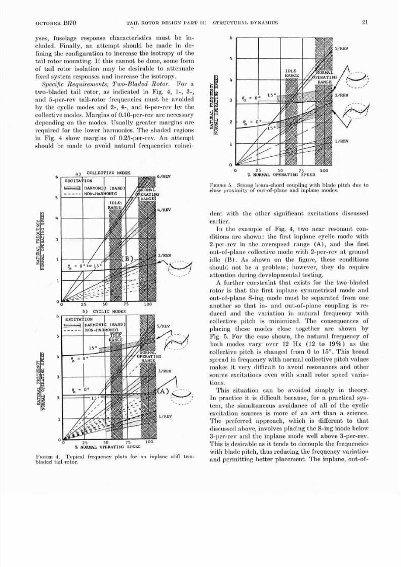
Specific Requ iremen ts, Two-Bladed Roto r.
For a
two-bladed tail rotor, as indicated in Fig.
4,
I-,
3-
and 5-per-rev tail-rotor frequencies must be avoided
by thc cyclic modes and 2-,
4-,
and 6-per-rev hy the
collective modes. AtIargins of 0 .10-per-rev ar e ncccssa ry
dcpending on the modes. Usually greatcr nlargins are
required for tbe lower I~armonics.Th e shaded regions
in Pig. 4 show ma rgins of 0.25-per-rev. An atte m pt
sllonld be made to avoid natural frequencies coinci-
b
CY CLIC
MODES
WOWL
OPERATIEX:
SPE E D
F~oune .
Typical
frequency
plots
for an inplane
stiff
Lwo-
bladed tai l
rotor.
0
2 5 50 7 5
100
N O W O P E P A T I f f i S P E E D
FIUUHI.;. St~ onp cam-chord coupling with blade
pitch due
to
close proximity
of
out of plnnc
a ~ l d
ll plan^
mnd~s
dcnt \\,it11 the other significant excitations discussetl
earlicr.
I n the exanlple of F ig. 4, two near resouant con-
clitions are shown: the first inplane cyclic mode with
2-per-rev in the overspeed rang e (A ), and th e first
out-of-plane collcctivc mode with 2-per-rev at ground
idlc ( B ) . As shown on the figurc, these conditions
sl~oulclnot be a problcm; llowever, they do require
attention during developmental testing.
A further constraint that exists for t l le two-bladed
rotor is that t l lc f irst inplane symmetrical mode and
out-of-],lane S-ing mode mu st be separa ted from one
another so that in- and out-of-plane coupling is re-
duced and th e variation in natur al frequency with
collective. pitch is minimized. Th e consequences of
placing these modes close togcthcr are shown by
Fig. 5. For the case shown, the natural frequency of
both modes va ry ovcr 1 2 Hz (12 to
19 )
a s t h e
collective
pitch is changed from 0 to 15 . This broad
spread in frequency wit11 normal collective pitch values
makcs it very difficult to avoid resonances and other
source excitations cven with small rotor speed varia-
tions.
This situation can be avoided simply in theory.
In practice it is difficult because, for a practical sys-
tem, the simultan eous avoidanc e of all of t he cyclic
excitation sources is more of a n ar t- han a science.
Th e preferred approac h, wliich is different to th at
discussed above, involves placing t he S-in g mode below
3-per-rev and t he inplane mode well above 3-per-rev.
This is desirahle as i t te nds to decouple the frequencies
with bladc pitch, thus reducing the frequency varia tio~l
and permitting better placement. The inplane, out-of-
8/10/2019 (Balke et al)Tail Rotor Design Part II Structural Dynamics.pdf
http://slidepdf.com/reader/full/balke-et-altail-rotor-design-part-ii-structural-dynamicspdf 7/15
22
BALKE, BEUNETT GAFFET A N D LYNN
2 5
50 75 100
N O W
OPERATINO SPEED
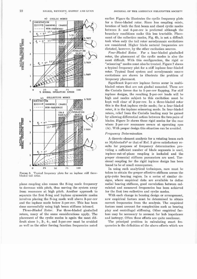
PIOURE
.
Typical
frequency
plots
for
an i11plnnc stiff three
bladcd
tai l
rotor.
plane coupling also causes the S-ing modc frequency
to decrease with pitch, thus moving the system away
from resonance a t high pitch. Another approach t o
separate the first S-ing and inplane symmetric modes
involves placing the S-ing mode well above 3-per-rev
and the inplane mode below 3-per-rev. This has been
done successfully using high be am stiffness inboard.
Three-Bladed Rotor. Fo r three-bladed gimballed
rotors, many of the same considerations apply. The
placement of the cyclic modes is again the most dif-
ficult since
1-
2-, 4-, and 5-per-rev must be avoided
as well as the other forcing function frequencies noted
JOURNAL OF
THE
IEKIC N HBLICOPTER SOCIBTY
earlier. Figure Ga illustrates th e cyclic freque ncy plots
for a three-bladed rotor. Since less coupling exists,
location of both th e first bcam an d chord cyclic modes
betwecn 2- and 4-per-rev is preferred although the
boundary conditions make this less tractable. Place-
me nt of t h e collective modes, Fig. Gb, is no t a difficult
task whcn only the tail rotor aerodynamic excitations
are considered. Higllcr blade natural frequencies are
dictated, however, by th e o ther excitation sources.
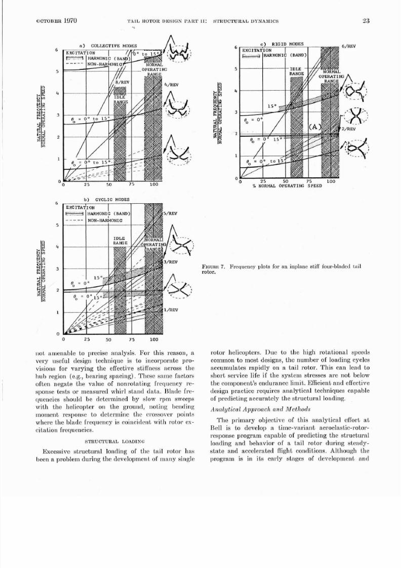
Pour-Bladed Rotov.
For a four-bladed gimballed
ro tor , the p lacement of the cycli c modes i s al so t h
most difficult. With this configuration, the rigid or
scissoring modes mnnst also be tre ate d. Fig ure 7 shows
a typical frequency plot for a stiff inpla ne four-blader1
rotor. Typical f ixed system and aerodynamic source
excitations a re shown t o i l lustrate t he pro ble ~n of
frequency placement.
Significant 2-pcr-rev inplane forces occur in multi-
bladed rotors that are not gimbal mounted. These are
the Coriolis forces due to 1-per-rev flapping. For stiff
inplane designs, the resulting 2-per-rev loads will be
high and modes subject to this excitation must bc
ke pt well clear of 2-per-rev . In a three-blad ed rotor
this is the first inplane cyclic mode; for a four-bladed
rotor, it is th e inpla ne scissoring mode. I n four-blade.1
rotors, relief from the Coriolis loading may be gained
by allowing diffcrential action between th e two pa irs of
blades. Fignre 7c shows these rigid modes for the case
wherc 2-per-rev resonance occurs at opera ting rpln
( A ) . With proper design this situation can be avoidcrl
Frequency Detevmination
A
discrete element analysis for a rotating beam such
as My klcstad's2 or ih a t of Ref. 3 gives satisfactory re-
sults for purposes of frequency determination pro-
viding a sufficient num ber of blad e segments is used,
inplane-out-of-plane coupling is included and the
proper elemental stiffness parameters are used. Tor-
sional coupling for the rigid inplane design has been
found to be of sma ll consequence.
I n using such analy tical techniques, care must be
taken to obtain t he proper effective stiffness across the
grip-yoke bearing region. I n series of similar de-
signs, where empirical data are available to definc
radial hearing stiffness, good correlation between cal-
culated and measured frequencies has been achieved
for the first two collective and cyclic modes.
Wit h each change in hearing design or arrangement,
new elnpirical factors must be determined to obtain
correct frequencies from the analysis . The empirical
facto rs mu st account for complexities such a s bearing
play and centrifugal stiffening. Other empirical fac-
tors may be necessary to account fo r hub impedance
and isotropy. O ften these effects ar e q uitc nonlinear.
The principal problem in calculating exact fre-
quencies is th e definition of the above effect- which are
8/10/2019 (Balke et al)Tail Rotor Design Part II Structural Dynamics.pdf
http://slidepdf.com/reader/full/balke-et-altail-rotor-design-part-ii-structural-dynamicspdf 8/15
OCTOBER 197 PALL
LlOTOR
DESIGN P A R T : STKUCTZTHALDYNAXICS 23
oat
amenable to precise analysis. For this reason, a
very useful design technique is to incorporate pro-
visions for varying the effective stiffness across the
huh region (e.g., bearing spacing). These same factors
often negate the value of nonrotating frequency re-
sponse tests or measured whirl stand rlata. Blade fre-
qucncics should be dcterrnined by slolv rpm sweeps
with the helicopter on the ground, noting bending
moment response to determine the crossover points
where th e blade frequency is coincident with ~. ot or x-
citation frequencies.
STRUCTUR L
LO A D I N G
Excessive structural loading of tlie tail rotor has
been a problem du ring tlie develop mcnt of m an y single
F ~ a m s
. Frequency plots
far
an inplane sti iour bladed
tail
rotor
rotor he1icol)ters. Du e t o th e high ro tatiolial speeds
common to most designs, tlie number of loading cycles
accumulates rapidly on a tail rotor. This can lead to
short service life if the system stresses are not below
th e component s en durance lim it. Efficient and effective
design practice requires analytical techniques capable
of predicting accurately the structural loading.
nal l~ t ical pproach and i l t e thods
T he primary objective of this alialytical effort a t
Bell is to develop a time-variant aeroelastic-rotor-
response program capable of predicting the structural
loading and behavior of a tail rotor during stead y-
state and accelerated flight conditions. Although the
program is in its ear ly stages of developm ent ant1
8/10/2019 (Balke et al)Tail Rotor Design Part II Structural Dynamics.pdf
http://slidepdf.com/reader/full/balke-et-altail-rotor-design-part-ii-structural-dynamicspdf 9/15
24
BALKE, BENNETT, G FFEY
AND
LYNN
7
STEADY
CALCULATED
EASURED
T R U E A I R S P E E D ,
KN
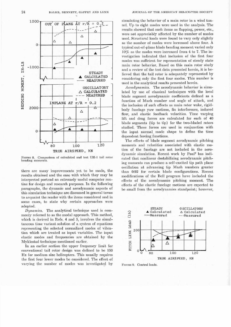
F ~ o u n c
.
Comparison
of
calculated and test UH-1
tail
rotor
bending moments.
there are many improvclncnts yet to he made, the
results obtained and the ease with wl~ ich hey ma y be
interpreted portend an extremely useful computer rou-
tine for design and research purposes. I n the following
par agr al~ hs, he dy namic and aerodynamic aspects of
this simulation techniqu e are discussed in general term s
to acqu aint tlle reader with th e items considcrcd a nd in
somc cases , to s t a te n~hycertain apl)roaches were
adopted.
D?~710?1aics. he analytical technique used is com-
monly referred to a s the modal approach. This m ethod,
which is derived in Refs.
4
and
5,
involves the simnl-
tancous time variant solution of a system of equations
representing the selected normalized modes of vibra-
tion which a re treated as inpu t variables. The inpu t
elastic modes and frequencies are obtained by the
Myklestad technique mentioned earlier.
I n a n earlier section the upper frequency limit for
conventional tail rotor design was defined to be 150
Hz for medium size helicopters. This usually requires
the first four lower modes be considered. Th e effect of
vary ing the numb er of modes was investigated by
JOURNAL OF THE A h l E R l C A N HELICOPTER SOCIETY
simulating the behavior of a main rotor in a wind tu n-
nel. Up to eight modes were used in the analysis. The
results showed t b at su ch items as flapping, power, etc.,
were no t appreciably affected b y th e number of modes
used. Structural loads were found to vary only slightly
as thc ntnnb cr of modes were increased above fou r. A
typical ou t-of-plane blade bending moment varied only
10
as the
nodes
were increased from
4
to 7. The in-
vestigation ind icated t h at inclusion of t he fir st four
modes was sufficient for representation of stea dy st ate
main rotor behavior. Based on this main rotor study
an d a review of th e test da ta presented herein, it is be-
lieved tha t the tail rotor is adequately represented by
considering only the first four modes. This numhcr is
used in the analy tical results presented herein.
Aero~ l yna~~a i c s
he aerodynamic behavior is simu-
lated by use of classical techniq ues with t he local
blade segment aerodynam ic coefficients defined as a
function of Mach number and angle of attack, and
th e inclusion of such effects as main rotor wake, rigid-
body fuselage yaw motions, fin interference, induced
flo~v, and elastic feedb ack velocities. Tim e var yin g
li ft ancl dra g forces ar e calculated for each of 40
blade segments tip to tip) for the two-bladed rotors
studied. These forces are used in conjunction with
the input no rm al mode shape to def ine the t ime
depend ent forcing functions.
T he cffects of blade segment aerodyn amic pitchin g
moments and velocities associated with elastic mo-
tion of the fuselage ar e not included in th e aero-
dynam ic simulation. Recent work by Pau lT has indi-
cated that nonlinear destabilizing aerodynamic pitch-
ing moments ran produce a self-excited ti p path planc
oscilla .tion a t advan cing tip Ma ch nu mbers g reater
t ha n
0.92
for certain blade configurations. Recent
modifications of th e Bell program have included th e
effects of the aerodynamic pitching moment. The
effects of t he elasti c fuselage lnotions are expected to
be small from the aerodynamics standpoint; however,
STEADY OSCILLATORY
P
P
A Calculated A Calculated
Measured Measured
T R U E A I R S P E E D KN
F l o u n ~ . Control
loads.

8/10/2019 (Balke et al)Tail Rotor Design Part II Structural Dynamics.pdf
http://slidepdf.com/reader/full/balke-et-altail-rotor-design-part-ii-structural-dynamicspdf 10/15
8/10/2019 (Balke et al)Tail Rotor Design Part II Structural Dynamics.pdf
http://slidepdf.com/reader/full/balke-et-altail-rotor-design-part-ii-structural-dynamicspdf 11/15
6 RALKE, BENNETT, GAFFEY
AND
YNN
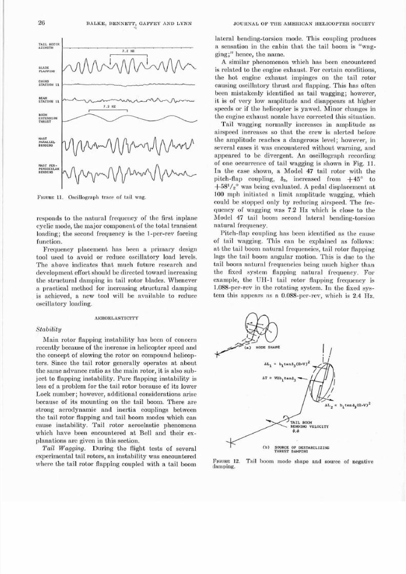
FIGURE1 Oscillagraph trace o tail r,ag.
responds to the natural frequcncy of the first inplane
cyclic mode, th e majo r component of th e total transie nt
loading; the second frequency is thc 1-pcr-rev forcing
function.
Frequency placement has been a primary design
tool used t o avoid or reduce oscillatory load levels.
Th e above indicates th at much futu re research and
development effort should be directed toward increasing
the structural damping in tail rotor blades. Whenever
a practical method for increasing structural damping
is achieved, a new tool will be available to reduce
oscillatoly loading.
AEROELASTICITY
Stability
M ain roto r flapping instabilit y has been of concern
recently because of t he increase in helicopter speed a nd
the conc ept of slowing th e rotor on compound lielicop-
ters. Since the ta il rotor generally operates a t abou t
the sam e advance ratio as the main rotor, i.t is also sub-
ject to flapping instabili ty. Pure flapping instabili ty is
less of a problem fo r th e tail rotor because of i ts lower
Lock number; however, additional considerations arise
because of i ts mounting on the tai l hoom. There a re
strong aerodynamic and inestia couplings between
the tail rotor flapping and tail boom modes which can
cause instabili ty. Tail rotor aeroelastic phenomena
u~hichhave been encountered a t Bell and the ir ex-
planations are given in this section.
Tail Wagging
During the flight tests of several
experimental tail rotors, a n instabili ty was encountered
where the tail rotor flapping coupled with a tail boom
JOURNAL OF THE A b I E R I C A N HELICOPTER SOCIETY
latcral bending-torsion mode. This coupling produces
a sensation in the cabin th at the tai l boom is wag-
ging; hence, th e name.
A similar phenomenon which has been encountered
is related to the engine exhaust. Fo r ce rtain conditions,
the hot engine cxhaust impingcs on the tail rotor
causing oscillatory thr ust and flapping. This has often
been mistakenly identified a s tail wagg ing; however,
i t is of very Ion. amplitude and disappears at higher
speeds or if the helicopter is yawed. Minor changes in
the engine exhaust nonzle hav e corrected th is situation.
Tail wagging nonnally
increases
in ampli tude as
airspeed increases so that the crew is alertetl before
the amplitude reaches a dangerous level;
how eve^.
in
several cases it was encountered without warning, and
appeared to bc divergent. An
oscillograph recording
of one occurrence of tail wagging is shown in Fig.
11
In the case shown, a Model 47 tail rotor with the
pitch-flap coupling,
$,
increased from +45' to
+581/20 was being evaluated.
A
pedal displacement at
100 mph initiatcd a limit amplitude wagging, which
could bc stopped only by redncing airspeed. The fre-
quency of wagging was 7.2 Hz n ~h ic h s close to the
Model 47 tail hoom sccond lateral hending-torsion
natural frequcncy.
Pitch-flap coupling has been identified as the canse
of tail n~agging.This can bc explained as follows:
a t the tail boom na tural frequencies, tail rotor f lapping
lags the tail Boom angular motion. This is due to the
tail boom natural frequencies being much higher than
the fixed system flapping natural frequency. For
example, the UH 1 tail rotor flapping frequency is
1.088-per-rev in th e rotating system.
I n
th e fixed sys-
tem thi s appe ars a s a 0.088-per-rcv, ~vllich s 2.4 H z .
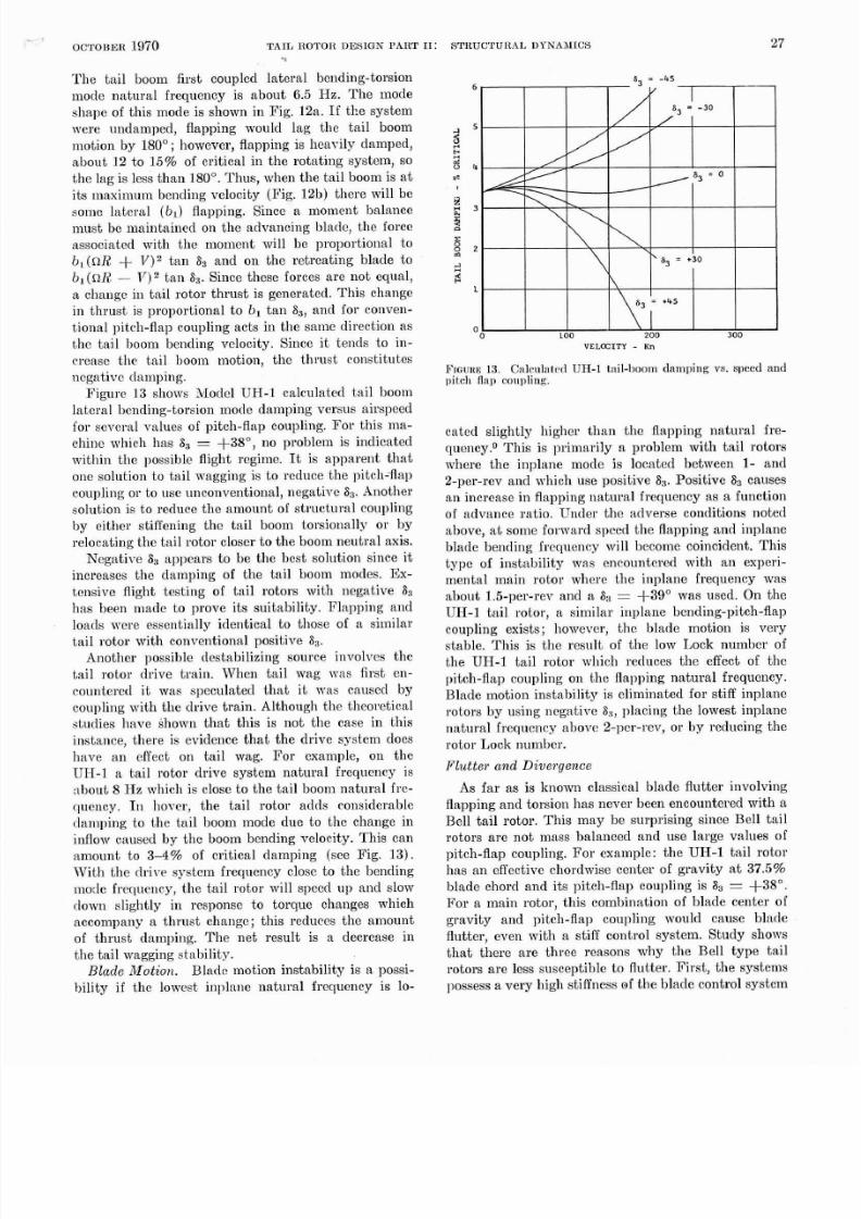
TAIL
B W H
BENTIN
VELOCITY
b) swnce
1
DESTABILIZ~G
THRUST DAMPI
F ~ o u ~ a2
Tail
boom mode shape and EOUtCe
of
negative
damping.
8/10/2019 (Balke et al)Tail Rotor Design Part II Structural Dynamics.pdf
http://slidepdf.com/reader/full/balke-et-altail-rotor-design-part-ii-structural-dynamicspdf 12/15
OCTOBER 1970
TAIL E O T O R DESIGN PART
T he tai l boom first coupled late ral be nding-torsion
mode natural frequency is about 6.5 Hz. The mode
shape of this mode is shown in Fig. 12% If tl:e system
were undamped, flapping would lag the tail boom
motion by 180 ; however, flapping is heavily damped,
abo ut 12 to 1 5% of critical in the rotating system, so
th e lag is less tha n 180'. Thus, when th e tail boom is a t
its maximum bending velocity (Fig. 12b) there will be
some lateral (bl) f lapping. Sincc a moment balance
must be maintained on the advancing b ladc, the force
associated with the moment will be proportional to
b l n R
V 2 an
Sg
and on the ret reat ing blade to
b , ( n R )2 t a n
S3.
Since thesc forces are not equal,
a changc in tail rotor th rus t is generated. Th is change
in thrust is proportional to bl tan
S3
and for conven-
tional pitch-flal~ oupling acts in the sam e direction as
the tail boom bending velocity. Since it tends to in-
crease tlie tail boom motion. thc thrust constitutes
negativc damping.
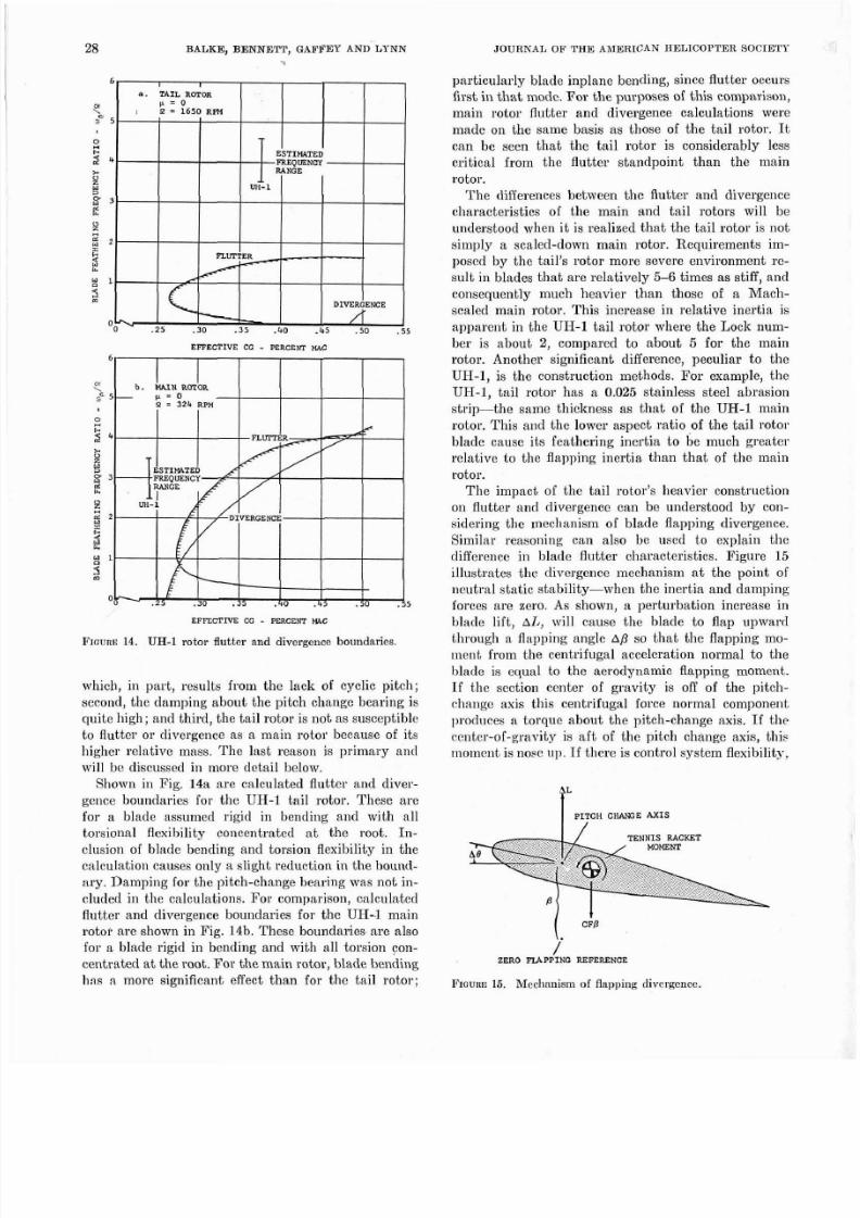
Figu re 13 shows ?vIodcl UH -1 calculated tail boom
latera l bending-torsion mode dam ping versus airspeed
for several values of pitch-flap coupling. For this m a-
chine wli~ ch as S3 +3S0, no problem is indicated
within the possible flight regime.
It
i s apparen t tha t
one solution to tail wagging is to rcduce the pitch-flap
coupling or to use unconv entional, negativc S3.Another
solution is to reduce tlie am oun t of struc tural coupling
by either stiffening tlie tail boom torsionally or by
relocating the tail rotor closer to the boom neutra l axis.
Ncgative
Sa
appears to be the bcst so lut io~ i ince i t
increases the damping of the tail boom modes. Ex-
tensive flight testin g of t ai l rotors with neg ative
8s
has been made to prove its suitabili ty. Flapping and
loads nrcre essentially identical t o those of a sim ilar
tail rotor with conventional positive Sa.
Another possible destabilizing source involves the
tail rotor drive train. When tail wag was first en-
countered it was speculated that i t mas caused by
coupling with th e drive tra in. A lthough tl ie theoretical
s tudies have Shown that this i s not the case in this
instance, there is evidence that the drive system does
have an effect on tail wag. For example, on the
UH-1 a tail rotor drive system natural frequency is
nhout 8 Ha which is close to th e tail boom nat ura l frc-
clucncy. I hovcr, the tail rotor adds considerable
damping to the tail boom mode due to the change in
inflow caused by the boom bending velocity. 'This can
am ou nt to 3-4% of critical dam ping (see Fig. 13).
With the drive system frequency close to th e bending
mode frequency, the tail rotor will speed up and slow
down slightly in response to torque changes which
accompany a thrus t change; this reduces the a~nount
of thrust damping. The net result is a decrease in
the tail wagging stabili ty.
Blade Motion.
Bladr motion instability is a possi-
bili ty if thc lo~v est nplnne natu ral frequency is lo-
11:
STRUCTURAL DYNAMICS
27
...
VELO ITY
Kn
FIGUR
3.
Calculnted UH I
tail-hoom
damping vs speed and
pitch
flap conpline
catccl slightly higher than the flapping natural fre-
quency.O This is primarily a problem with tail rotors
where the inplane mode is located between 1 and
2-per-rev and which use positive
SB
Positive
S3
causes
an increase in flapping natu ral frequcncy a s a function
of advance ratio. Under the adverse conditions noted
above, a t some forward speecl th e flapping a nd inplane
blade bending frequency will become coincident. This
typ c of in stabilit y was encountered with an experi-
mental main rotor where the inplane frequency was
about 1.5-per-rev and a
S3
+39 was used. On the
UH-1 tail rotor, a similar iuplane bending-pitch-flap
coupling exists; however, thc blade motion is very
stable. Thi s is th e rcsult of t he low Lock num ber of
the UH-1 tail rotor wliich reduces the effect of the
pitch-flap coupling on the flapping natural frequency.
Blade motion instability is eliminated for stiff inplane
rotors by using negative
SR
placing the lowest inplane
natural frequency above 2-per-rev, or by reducing the
rotor Lock number.
Flut ter and Divergence
As far as is known classical blade flutter involving
flapping and torsion has never been encountered with a
Bell tail rotor. This may be surprising since Bell tail
rotors are not mass balanced and use large values of
pitch-flap coupling. For example: the UH-1 tail rotor
has a n effective chordwise center of grav ity a t 37.5%
blade chord and its pitch-flap coupling is
S3
+38O.
For a m ain rotor, this com bination of blade center of
gravity and pitch-flap coupling n~ ou ld cause blade
flutter, even with a stiff control system. S tud y shows
that there are three reasons why the Bel l type tai l
rotors are less susceptible to flutter. First, tlie systems
l>ossessa very high stiffness of the blad e control system
8/10/2019 (Balke et al)Tail Rotor Design Part II Structural Dynamics.pdf
http://slidepdf.com/reader/full/balke-et-altail-rotor-design-part-ii-structural-dynamicspdf 13/15
28
BALKE BENNElT
GARFEY
AND
LYNN
4
EFFECTIVE
CO
PERCENT
M C
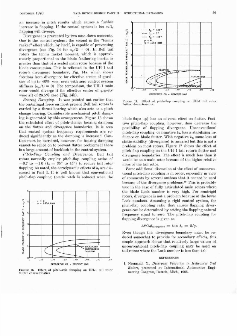
P~ouns14. UH 1 rotor flutter and divergence boundaries
which, in part, results from the lack of cyclic pitch;
second, the damping about the pitch change hearing is
quite high; and third, th e tail rotor is not a s susceptible
to fluttcr or divergence as a main ro tor because of its
higher relative mass. The last reason is primary and
will be discussed in more detail below.
Shown in Fig. 148 ar e calculated flutter and diver-
gence boundaries for the UH-1 tail rotor. These are
for a blade assumed rigid in bending and with all
torsional flexibility concentrated a t the root. In-
clusion of b lade bending a nd torsion flexibility in th e
calculation causes only a slight reduction in tlie bound-
ary. Dam ping for the pitch-change bearing was n ot in-
cluded in tlie calculations. For comparison, calcnlatcd
flutter and divergence boundaries for the UH-1 main
rotor are shown in Fig. 14b. These boundarie are also
for a blade rigid in hending and with all torsion con-
centrated a t the root. For t he main rotor, blade bending
has a more significant effect than for the tail rotor;
particularly blade inplane bend ing, since flutter occurs
first in th at mode. For the purposes of this comparison,
main rotor fiutter and divergence calculations were
made on th e same basis as those of the ta il rotor. It
can be seen that the tail rotor is considerably less
crit ical from the flutter standpoint than the main
rotor.
The differences between the flutter and divergence
characteristics of the main and tail rotors will be
understood when it is realized th at th e ta il rotor is not
simply a scaled-down main rotor. Requiremeiits im-
posed by the tail 's rotor more severe environment rc-
sult in blades th at are relatively
6
times as stiff, and
consequently much heavier than those of a Mach-
scaled main rotor. This increase in relative inertia is
apparent in the UH-1 tail rotor where the Lock num-
ber is about 2 compared to about for the main
rotor. Another significant difference, peculiar to the
UH-I, is the construction methods. For example, the
UH-I, tail rotor has a 0.025 stainless steel abrasion
strip-the same thickness as th a t of the UH-1 main
rotor. This and the lower aspect ratio of t he ta il rotor
blade cause its feathe ring inertia to be much gre ater
relative to the flapping inertia than th at of the main
rotor.
The impact of the tail rotor's heavier construction
on flutter and divergence can he understood by con-
sidering the mechanism of blade flapping divergence.
Similar reasoning can also be used to explain the
difference in blade flutter characteristics. Figure 15
illustrates tl ie divergence mechanism a t the point o f
neu tral static stability-when the inertia an d dam ping
forces are zero. As shown, a perturhation increase in
blade lift, AL will cause the blade to flap upward
through a flapping angle p so that the flapping mo-
ment from the centrifugal acceleration normal to the
hlade is equal to the aerodynamic flapping moment.
If the section center of gravity is off of the pitch-
change axis this centrifugal force normal component
produces a torquc about the pitch-change axis. If tlie
center-of-gm vity is af t of t he pitch change axis, this
moment is nose op. f there is control system flexibility,
PITCH C-E XIS
CFP
ZERO FIA PPIN G
REFERENCE
Froun~15. Mechanism
of
flapping divergence
8/10/2019 (Balke et al)Tail Rotor Design Part II Structural Dynamics.pdf
http://slidepdf.com/reader/full/balke-et-altail-rotor-design-part-ii-structural-dynamicspdf 14/15
o c l . o n ~ n 970
TAIL
ROTOR DESIGN PART 11: STRUCTITRAL DPNhnIrcs 29
an increase in pitch results which causes a further
increasc in flapping. If the control system is too soft,
flapping will diverge.
Divergence is prcvented by two nose-down moments.
One is the control system; the second is the tennis
racket effect which, by itself, is capable of preventing
divergence (see Fig.
14
for w /n
0 ) .
I n Bell ta i l
rotors the tennis racket moment, which is approxi-
matcly proportional to the blade feathering inertia is
greate r thn n tha t of a scaled main rotor because of th e
blade construction. This is reflected in the
UH-1
ta i l
rotor 's divergence hounda~y,Fig.
14a,
which shows
freedom fro m divergence for effective center of grav i-
ties of ul) to
48%
mac even with zero control system
stiffness ( ~ , / n 0 ) . For comparison, the UH-1 main
roto r would diverg e if the effective center of g rav ity
were a ft of 26.5% mac (Fig. 14b) .
Beal ing Dan~ping.
It was pointed out earlier that
the centrifugal force on mo st present Bell tail rotors is
carried by a thr ust hearing which also acts a s a pitch
change hearing. Considerable mechanical pitch damp-
ing is generated by th is arrangement. Figure 16 shows
the calculated effect of pitch-change bearing damping
on the flutter and divergence boundaries.
It
is seen
that control system frequency requirements are re-
duced significantly as t l ~ e amping is incrensctl .
CRU-
tion m ust be exercised, hon ~ev er, or bearing dampin g
cann ot he relied on to prevent flutter problems if there
is a large amo unt of bncklash in the control system.
Pitch-Flap Coupling and Divergence. Bell tail
rotors normally employ pitch-Hap coupling ratios of
-0.7 to -1.0
a3 35
to 45 ) to rcducc tail rotor
flapping. As noted, t he aerodynam ic effects of 8% re dis-
cussed in Part I
It
is well known that conventional
pitch-flap coupling (hlad e pitch is reduced when th e
E PFE C T N E CG
PERCENI U C
P ~ c u n ~6.
Effect of pitch-axie damping on UH-1 tnil rotor
flutter
characteristics.
EFFE TWE
E PERCENI PUD
FIOURE7 Effcct of pitch-flap eaupliag on UH-1 t n i l ru lor
flutter characteristics.
blade flaps up) has an adverse effe ct on flu tter. Posi-
tive pitch-flap coupling, however, does decrease the
possibility of flapping divergence. Unconventionnl
pitch-flap coupling, or negative S3, has a stabilizing in-
fluence on hlade flutter. With negative Sa, some loss of
stat ic stability (divergence) is incurred bu t this is no t a
problem on most rotors. Figure 17 shows the effect of
pitch-flap coupling on the UW-1 tail rotor's flutter and
divergence boundaries. Thc cffect is much less than it
nrould he on a main rotor because of t he lrigher re1 at ve
illass of the ta il roto r.
Solne atld itio nal discussion of th e effect of unco nve n-
tional pitch-flap coupling is in ortler, especially in view
of comments by several authors t ha t i t can not be used
because of th e divergence problems.1° Thi s is prob ably
true in the case of fully articulated main rotors where
the hlade Lock number is very high. For semirigid
rotors, divergence is not a problem because of th e lower
Lock numbers. Assumii~ga rigid control system, the
pitch-flap coupling ratio that causes flapping diver-
gence can be determined by settin g the flapping nat ura l
frequency equal to zero. The pitch-flap coupling for
flapping divergence is given as
AB/APai
y.rr.c p.
a n
Sn
Wy.
Even though this divergence boundary must be re-
duced somewhat to provide for secondary effects, this
simple approach shows that relatively large values of
unconventional pitch-Hap coupling may be used on
tail rotors where th e Lock numb er is less th an 4.0.
REFERENCES
1. Normand, Y., Diverge7~t Vibration BL Helicopter
ail
Rotors presented nt Inter~ iation al Antomotive Engi-
neering Congress, Detroit ,
Mich.,
1965.

8/10/2019 (Balke et al)Tail Rotor Design Part II Structural Dynamics.pdf
http://slidepdf.com/reader/full/balke-et-altail-rotor-design-part-ii-structural-dynamicspdf 15/15
30 BALKE BENNETT GAFFES *XI YSS
JOURNAL
OP
THE AMERICAN
RELICOPTER SOCIETY
2 Myk lestad, N . O., Vibration Analysis, McCram -Hill Book
Co., Inc., Nem I'ork, 1944.
3 Bla~~keush ip ,. L. and Harvcy, I< I1. A D igita l An-
alysis for Helicopter Per form al~c c nd Roto r Blade Bend-
ing Rton~ents, 7,
4)
J. America>& elicopter Society
(Oetobcr 1962).
4.
Etkin, Bernard, Dynanlics of Flight, John Wiley aud
Sons, Inc., New York, 1959.
5. Timosheuko, S., Vibration Problems in Engineering,
D.
\'a.~~N ostrand om pany, Inc., Prinecton, N.J., 1955.
6
Gessoxx., I and Myers,
G. C .
Jr., Aerodynanzics of the
Helicopter, The, Th e AlacMilliam Co., Nexv I'ork, 1952.
i
aul, 11 . F. A Self-Excited Ro tor Blade Oscillation at
High Subsonic Mach Numbers, 14 (1) J . American
Helicopter Society (January 1969).
8. Crimi, P., Theoretical Prediction of the Flow in the
Wake of
a
Helicopter Rotor, CAL No. BB-1994-S-1,
Cornell Aeronautical Laboratory, Inc., Buffalo, N.Y.,
September 1965.
9. Gatiey, T. M., The Etieot of Positive Pitch-Flap
Coupling (Negative S3 on Rotor Blade Motion Sta-
bility and Flapping,
J.
Amelican Helicopter Society,
14 (2) (April 1969).
10. Mil, M. L. et al, Helicopte1.s-Calculation and Design
Volume I Aerodynamics, NASA Technical Translation,
NASA T T F4 94 , September 1967.