badminton
DESCRIPTION
Her kan du købe Badminton online til de laveste priser på nettet - nettraening.dk samler udvalget og giver dig Badminton billig Hvis ikke du fandt noget i kategorien Badminton så klik dig rundt og se vores store udvalg i andre kategorier.TRANSCRIPT

The mode shapes of a tennis racket and the effects of vibrationdampers on those mode shapes
Nicholas Timmea� and Andrew MorrisonIllinois Wesleyan University, P.O. Box 2900, Bloomington, Illinois 61702
�Received 7 August 2008; revised 7 April 2009; accepted 8 April 2009�
The vibrational behavior of a tennis racket was studied using a speckle-pattern interferometrysystem. Specifically, the first 12 mode shapes of a racket are shown and discussed. In addition, thespeckle-pattern interferometry system was used to compare the effects of four commerciallyavailable vibration damping systems. It was found that these vibration dampers produce a variety ofeffects on the vibrational behavior of the racket, though these effects may not be noticeable duringplay. © 2009 Acoustical Society of America. �DOI: 10.1121/1.3126343�
PACS number�s�: 43.40.At, 43.20.Ks �TDR� Pages: 3650–3656
I. INTRODUCTION
A great deal of research has been performed concerningthe mechanical behavior of the tennis racket.1–8 The purposeof this project with regard to tennis rackets was twofold: toobserve the vibrational behavior of a tennis racket using aspeckle-pattern interferometry �SPI� system and to test theeffects of various commercially available vibrational damp-ing systems on the vibrational behavior of a tennis racketusing that SPI system. While some publications have dis-cussed specifically the vibrational behavior of the tennisracket,7,8 as far as the author is aware, no research has em-ployed SPI to directly observe the vibrational behavior of atennis racket and no research has yielded detailed informa-tion regarding the first 12 mode shapes. In addition, severalauthors studied the effects of vibration dampers on the me-chanical performance of the tennis racket,9–12 but again noresearch has directly studied the changes in vibrational be-havior caused by vibration dampers. The vibration dampingsystems, of which there are several distinct designs, are ad-vertised as lessening uncomfortable high frequency vibra-tions in the racket that lead to a bad “feeling” in the racket asexperienced by the player. The purpose of this paper is not todirectly assess the claimed performance of the vibrationdamping systems with regard to the feeling experienced bythe player; rather the goal is to observe what effects, if any,these systems have on the mode shapes and vibrational am-plitude of a tennis racket.
II. SPI SYSTEM
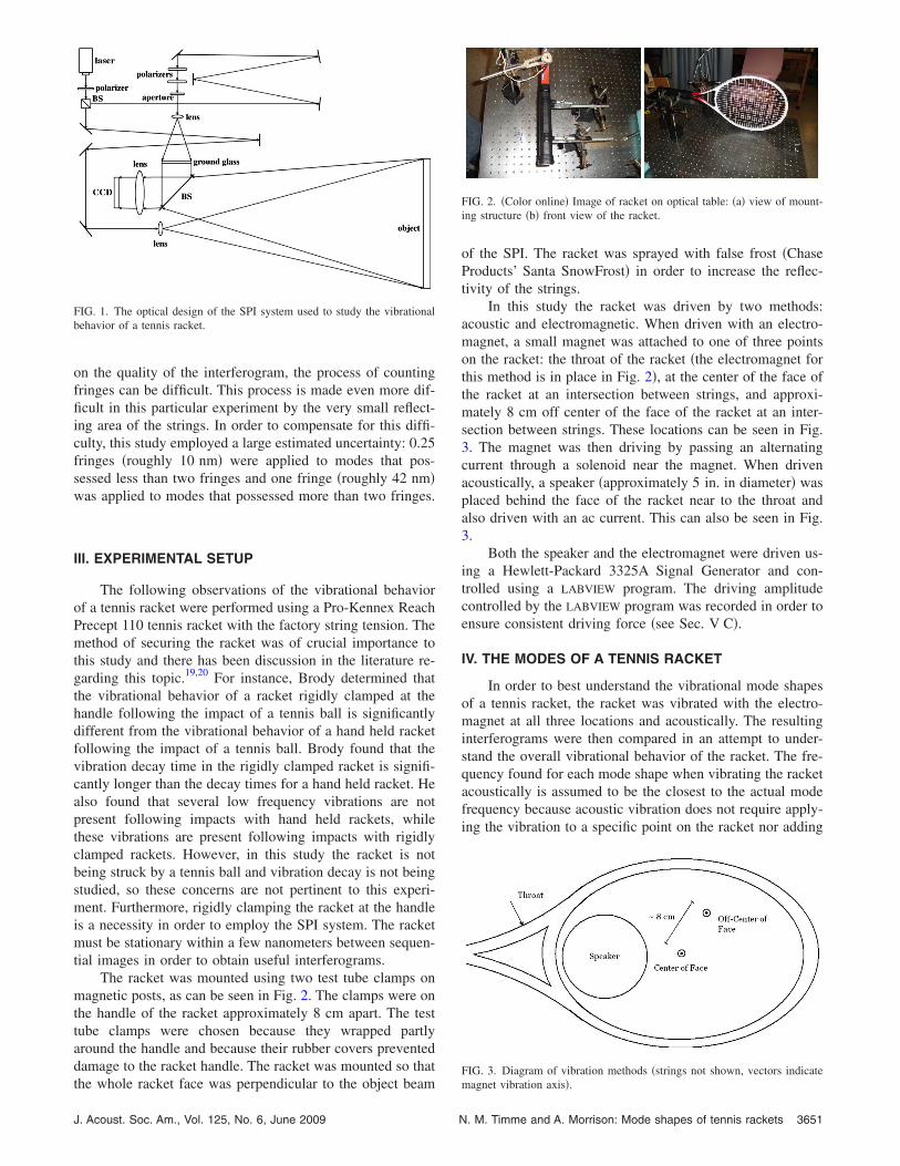
SPI represents a relatively low cost, real time, non-destructive method for measuring the vibrations of varioussurfaces. Moore, Lokberg, and Rosvold presented generallyequivalent, though differently phrased, overviews of thetheory involved in SPI.13–17 The SPI setup used in these ex-periments can be found in Fig. 1.
a�Present address: Indiana University, 727 E. Third St., Bloomington, IN47405-7105. Author to whom correspondence should be addressed. Elec-
tronic mail: [email protected]3650 J. Acoust. Soc. Am. 125 �6�, June 2009 0001-4966/2009/1
A laser beam �in this case a 532 nm HLaser OptoTech�is divided by a beam splitter into a reference and objectbeam. The object beam strikes an object and is partially re-flected into a camera. The reference beam is directed to acharge coupled device camera �Unibrain Fire-I firewire�through a beam splitter that serves to recombine the objectand reference beams. The optical system was designed suchthat the size of an individual speckle seen by the camera wasapproximately equal to the size of a pixel of the camera. Inorder to minimize background vibration, the system ismounted on a Newport RS 4000 floating optical table.
To produce interferograms in traditional SPI systems,one image is taken prior to the onset of vibration and subse-quent images of the object during vibration are subtractedfrom the initial image. However, this method will fail as thebeam decorrelates. Thus, in the setup used by this experi-ment interferograms were produced by continually takingand subtracting pairs of images during vibration, as was sug-gested by Moore.18 This process was accomplished with aLABVIEW program.
The irradiance of a pixel in an interferogram produce bythe SPI system is given by Eq. �1�.15,16
Imn = �AmnJ0�4��z
��� . �1�
In Eq. �1� m and n refer to the nth image subtracted fromthe mth image, Amn is a proportionality constant for all pix-els, �z refers to the vibrational amplitude of an individualspeckle on the object, � is the wavelength, and J0 is a zero-order Bessel function of the first kind. Therefore, on inter-ferograms, regions of no vibration �nodes� appear white andincreasing vibrational displacement results in a sequence ofalternating light and dark fringes as a result of the oscillationof the Bessel function. The sequence of fringes is similar toa contour plot in that densely arranged fringes imply largechanges in displacement. Using 1 a direct measurement ofthe maximum vibrational amplitude can be made by count-ing fringes. The white area of nodes corresponds to zerovibrational amplitude, the light area of the first fringe corre-sponds to the next maximum in 1 �given a wavelength of532 nm this is approximately 42 nm�, the second fringe cor-
responds to approximately 85 nm, and so forth. Depending© 2009 Acoustical Society of America25�6�/3650/7/$25.00
on the quality of the interferogram, the process of countingfringes can be difficult. This process is made even more dif-ficult in this particular experiment by the very small reflect-ing area of the strings. In order to compensate for this diffi-culty, this study employed a large estimated uncertainty: 0.25fringes �roughly 10 nm� were applied to modes that pos-sessed less than two fringes and one fringe �roughly 42 nm�was applied to modes that possessed more than two fringes.
III. EXPERIMENTAL SETUP
The following observations of the vibrational behaviorof a tennis racket were performed using a Pro-Kennex ReachPrecept 110 tennis racket with the factory string tension. Themethod of securing the racket was of crucial importance tothis study and there has been discussion in the literature re-garding this topic.19,20 For instance, Brody determined thatthe vibrational behavior of a racket rigidly clamped at thehandle following the impact of a tennis ball is significantlydifferent from the vibrational behavior of a hand held racketfollowing the impact of a tennis ball. Brody found that thevibration decay time in the rigidly clamped racket is signifi-cantly longer than the decay times for a hand held racket. Healso found that several low frequency vibrations are notpresent following impacts with hand held rackets, whilethese vibrations are present following impacts with rigidlyclamped rackets. However, in this study the racket is notbeing struck by a tennis ball and vibration decay is not beingstudied, so these concerns are not pertinent to this experi-ment. Furthermore, rigidly clamping the racket at the handleis a necessity in order to employ the SPI system. The racketmust be stationary within a few nanometers between sequen-tial images in order to obtain useful interferograms.
The racket was mounted using two test tube clamps onmagnetic posts, as can be seen in Fig. 2. The clamps were onthe handle of the racket approximately 8 cm apart. The testtube clamps were chosen because they wrapped partlyaround the handle and because their rubber covers preventeddamage to the racket handle. The racket was mounted so that
FIG. 1. The optical design of the SPI system used to study the vibrationalbehavior of a tennis racket.
the whole racket face was perpendicular to the object beam
J. Acoust. Soc. Am., Vol. 125, No. 6, June 2009 N
of the SPI. The racket was sprayed with false frost �ChaseProducts’ Santa SnowFrost� in order to increase the reflec-tivity of the strings.
In this study the racket was driven by two methods:acoustic and electromagnetic. When driven with an electro-magnet, a small magnet was attached to one of three pointson the racket: the throat of the racket �the electromagnet forthis method is in place in Fig. 2�, at the center of the face ofthe racket at an intersection between strings, and approxi-mately 8 cm off center of the face of the racket at an inter-section between strings. These locations can be seen in Fig.3. The magnet was then driving by passing an alternatingcurrent through a solenoid near the magnet. When drivenacoustically, a speaker �approximately 5 in. in diameter� wasplaced behind the face of the racket near to the throat andalso driven with an ac current. This can also be seen in Fig.3.
Both the speaker and the electromagnet were driven us-ing a Hewlett-Packard 3325A Signal Generator and con-trolled using a LABVIEW program. The driving amplitudecontrolled by the LABVIEW program was recorded in order toensure consistent driving force �see Sec. V C�.
IV. THE MODES OF A TENNIS RACKET
In order to best understand the vibrational mode shapesof a tennis racket, the racket was vibrated with the electro-magnet at all three locations and acoustically. The resultinginterferograms were then compared in an attempt to under-stand the overall vibrational behavior of the racket. The fre-quency found for each mode shape when vibrating the racketacoustically is assumed to be the closest to the actual modefrequency because acoustic vibration does not require apply-ing the vibration to a specific point on the racket nor adding
FIG. 2. �Color online� Image of racket on optical table: �a� view of mount-ing structure �b� front view of the racket.
FIG. 3. Diagram of vibration methods �strings not shown, vectors indicate
magnet vibration axis�.. M. Timme and A. Morrison: Mode shapes of tennis rackets 3651

mass to the racket as was the case with the electromagneticmethod. However, by vibrating the racket at the two pointson the face, we can gain useful information regarding thevibrational response of the racket to vibrations applied tothose specific regions. From these measurements, we wereable to identify the first 12 mode shapes. In naming themodes, we have adopted a notation similar to the notationused in the naming of the modes of circular plates. Thus, themodes are named by an ordered pair �x ,y�, where x is thenumber of nodal diameters and y is the number of nodalcircles. In addition, modes with the same number of nodaldiameters and nodal circles but possessing different shapesare noted by a letter following the number of nodal diam-eters. A representative interferogram for each mode shapecan be seen in Fig. 4.
Some modes were not seen for each method of vibrationand the modes that were observed appeared at slightly dif-ferent frequencies depending on the method of vibration �seeFig. 5�. The uncertainty for the mode frequencies is, relativeto the overall frequency, very small at only 3 Hz. For thisreason, error bars are not included in Fig. 5.
It was also observed that several mode shapes differedslightly between methods of vibration. For instance, whenthe racket was vibrated acoustically, the nodal line in the�1a ,1� mode was rotated approximately 30° counterclock-wise. Also, for the �1c ,0� mode, the nodal arc was distortedwhen the racket was vibrated at both positions on the face ofthe racket.
The mode shapes in Fig. 4 can be divided into two gen-eral regimes: high frequency �mode �0,1� and higher� and
FIG. 4. The mode shapes of a tennis racket �a� �1a ,0�: Acoustic 67 Hz �b��1b ,0�: Acoustic 114 Hz �c� �1c ,0�: Acoustic 205 Hz �d� �2a ,0�: Acoustic349 �e� �2b ,0�: Acoustic 432 �f� �0,1�: Acoustic 562 Hz �g� �1a ,1�: Throat895 Hz �h� �1b ,1�: Acoustic 909 Hz �i� �2a ,1�: Off center 1154 Hz �j��2b ,1�: Acoustic 1186 Hz �k� �0,2�: Center 1270 Hz �l� �3,1�: Throat1476 Hz.
low frequency �mode �2b ,0� and lower�. For the high fre-
3652 J. Acoust. Soc. Am., Vol. 125, No. 6, June 2009
quency regime, the racket appears to behave like a clampedelliptical membrane. For these modes the racket frame isalways a node and the lowest frequency mode is the �0,1�, asis the case for a clamped elliptical membrane. As the modefrequency increases nodal diameters and nodal circles ap-pear, as is the case for a clamped elliptical membrane. Thus,in this regime vibration only occurs in the strings. For thelow frequency regime complicated behavior is observed.Modes �1b ,0� and �1c ,0� are similar to a cantilever. Thus,the strings and frame behave as one body. However, modes�1a ,0�, �2a ,0�, and �2b ,0� are similar to the modes seen fora free elliptical membrane. Thus, for these modes the framevibrates, but the frame and strings do not behave as one bodyas they did for the �1b ,0� and �1c ,0� modes. Therefore, inthe low frequency regime the frame and string interact in acomplicated fashion, but for the high frequency regime theracket is consistently similar to a clamped elliptical mem-brane. This interesting behavior underscores the complexityof the interaction between the strings and the frame in thetennis racket system as a whole.
A. The sweet-spot controversy
There has been some disagreement within the literatureregarding the “sweet spot” of a tennis racket.3,5,6,8,12,20 Tennisplayers generally refer to the sweet spot as the region of theracket face where, if the ball is struck there, the hit “feelsgood” or “feels effortless” to the player and the ball travelslarge distances. This project did not hope to address the feelassociated with ball-racket impacts on various parts of theracket, nor the relationship between the ability of the racketto impart a large velocity on the ball and the location of theimpact. However, several authors considered the possibilitythat the sweet spot is a node of a particularly strong lowfrequency mode of vibration.3,5,6,8,12,20 By using SPI, thisproject has been able to clearly identify the nodal regions ofthe low frequency modes. Furthermore, several authors notedthat the average impact time of a tennis ball �approximately5 ms� is roughly one-half of 1 cycle of vibration for modesnear 100 Hz.6,8 Thus, when the ball is struck in the nodalregion, less energy is spent in stretching the racket face and
FIG. 5. The mode frequencies of a tennis racket vibrated by four differingmethods.
more energy is imparted to the ball than if the ball had struck
N. M. Timme and A. Morrison: Mode shapes of tennis rackets

an anti-node. There is some ambiguity regarding preciselywhich mode is responsible for this behavior. For instance,Brody claimed that the main mode responsible for this be-havior is the arc shaped mode �the �1b ,0� and �1c ,0� modesas they are being referred to here� and that this is the funda-mental mode.12 Regardless of precisely which mode is re-sponsible, from the mode shapes observed here it is apparentthat the nodes of the lowest five modes all overlap in roughlythe area of the center of the face. Thus, an impact in this areamay be expected to excite these modes less than an impact inanother region of the face, resulting in a larger amount ofenergy input to the ball for impacts in the center of the facein comparison to impacts in other regions of the face. Indeed,when the racket was vibrated at the center of the face the�1b ,0�, �2a ,0�, and �2b ,0� modes were not seen and the�1a ,0� mode was shifted approximately 30% lower, as canbe seen in Fig. 5. In addition, four of the lowest five modeswere seen unshifted when the racket was vibrated off thecenter of the face �i.e., away from the possible sweet spot�.Thus, using SPI, we are able see a clear difference in vibra-tional behavior based on the location of vibration on the faceand this behavior seems to correlate with the sweet spot be-havior.
V. THE EFFECTS OF VIBRATION DAMPERS
A. Vibration damping systems
There are several vibration damping systems commer-cially available today. In this paper a sample of four suchmodels were studied: the Wilson Vibra-Fun �specifically therectangular model�, the Prince NXG Silencer, the HeadSmartsorb, and the Babolat RVS. All of these models costaround five dollars and claim to offer a low cost way toimprove racket feel by diminishing uncomfortable high fre-quency racket vibrations. All four models of vibration damp-ers attach to the racket near the bottom of the racket head.All models supplied rudimentary directions about how toattach the device to the racket and these were followed ex-plicitly. The models attached to the racket can be seen in Fig.6.
All four models are made primarily of flexible rubber-like materials. The Prince and Wilson models are similar inthat they attach to the racket by wedging between severalstrings. In this way, they are in contact with several strings,though the Prince model is in contact with several more thanthe Wilson model. The Head model winds between severalstrings in such a way that for each string, the vibrationdamper crosses the string on the opposite side compared tothe lowest perpendicular string. It is also pressed up againstthis perpendicular string. The Babolat model is wedged be-tween several strings, similar to the Prince model, but it alsorests against the frame and has attached to it a small metalweight. The masses of the four models were �Wilson� 2.32 g,�Prince� 5.92 g, �Head� 2.43 g, and �Babolat� 6.71 g.
B. Comparison mode frequencies
For the purposes of comparing the effects of the vibra-tion dampers on the vibrational behavior of the racket, the
lowest eight modes, mode �2b ,1�, and mode �0,2� were ob-J. Acoust. Soc. Am., Vol. 125, No. 6, June 2009 N
served by vibrating the racket acoustically. The acousticmethod was used because it produced the most mode shapesand because it did not require adding mass to the racket orvibrating the racket at a specific point, as was the case withthe electromagnetic method. The mode frequencies observedin this comparison can be seen in Fig. 7. As before, at 3 Hzthe uncertainty for the mode frequencies is relatively verysmall compared to the mode frequency. Therefore, error barsare not included in Fig. 7. Also, there were several modesthat were heavily distorted �mode �2a ,0� for the Princemodel, �2b ,0� for the Prince, Head, and Wilson models, andmodes �1a ,1� and 2b ,1 for the Head model� that are in-cluded in Fig. 7, but which will be specifically addressed�see Sec. V D�.
From the results in Fig. 7, it is apparent that the vibra-tion dampers have a relatively small effect on the lowermode frequencies, but that they do significantly affect thehigher mode frequencies. For instance, the Head modelshifted the mode �0,1� and �1a ,1� frequencies significantlylower than when the racket was undamped. Also, the �1a ,1�and �1b ,1� mode frequencies were switched when the Wil-
FIG. 6. �Color online� The vibration dampers attached to the racket �elec-tromagnet vibration method shown, but not employed�: �a� Babolet model,�b� Head model, �c� Prince model, and �d� Wilson model.
FIG. 7. The mode frequencies of a tennis racket undamped and with damp-
ers in place.. M. Timme and A. Morrison: Mode shapes of tennis rackets 3653
son vibration damper was in place. Mode frequencies werenot only shifted lower. For instance, the Wilson modelshifted the �1a ,1� and �0,1� mode frequencies higher. Fi-nally, several modes were eliminated entirely as will be fur-ther discussed in Sec. V D.
C. Driving amplitude
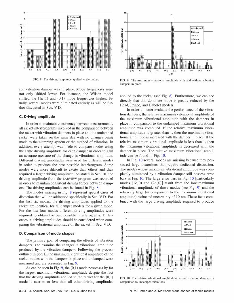
In order to maintain consistency between measurements,all racket interferograms involved in the comparison betweenthe racket with vibration dampers in place and the undampedracket were taken on the same day with no changes beingmade to the clamping system or the method of vibration. Inaddition, every attempt was made to compare modes usingthe same driving amplitude for each damper in order to gainan accurate measure of the change in vibrational amplitude.Different driving amplitudes were used for different modesin order to produce the best possible interferogram. Somemodes were more difficult to excite than others and thusrequired a larger driving amplitude. As stated in Sec. III, thedriving amplitude from the LABVIEW program was recordedin order to maintain consistent driving forces between damp-ers. The driving amplitudes can be found in Fig. 8.
The modes missing in Fig. 8 represent special cases ofdistortion that will be addressed specifically in Sec. V D. Forthe first six modes, the driving amplitudes applied to theracket are identical for all damper models for a given mode.For the last four modes different driving amplitudes wererequired to obtain the best possible interferograms. Differ-ences in driving amplitudes should be considered when com-paring the vibrational amplitude of the racket in Sec. V D.
D. Comparison of mode shapes
The primary goal of comparing the effects of vibrationdampers is to examine the changes in vibrational amplitudeproduced by the vibration dampers. Following the processoutlined in Sec. II, the maximum vibrational amplitude of theracket modes with the dampers in place and undamped weremeasured and are presented in Fig. 9.
As can be seen in Fig. 9, the �0,1� mode possesses by farthe largest maximum vibrational amplitude despite the factthat the driving amplitude applied to the racket for the �0,1�
FIG. 8. The driving amplitude applied to the racket.
mode is near to or less than all other driving amplitudes
3654 J. Acoust. Soc. Am., Vol. 125, No. 6, June 2009
applied to the racket �see Fig. 8�. Furthermore, we can seedirectly that this dominate mode is greatly reduced by theHead, Prince, and Babolet models.
In order to better evaluate the performance of the vibra-tion dampers, the relative maximum vibrational amplitude ofthe maximum vibrational amplitude with the dampers inplace in comparison to the undamped maximum vibrationalamplitude was computed. If the relative maximum vibra-tional amplitude is greater than 1, then the maximum vibra-tional amplitude is increased with the damper in place. If therelative maximum vibrational amplitude is less than 1, thenthe maximum vibrational amplitude is decreased with thedamper in place. The relative maximum vibrational ampli-tude can be found in Fig. 10.
In Fig. 10 several modes are missing because they pos-sessed large distortions that require dedicated discussion.The modes whose maximum vibrational amplitude was com-pletely eliminated by a vibration damper still possess errorbars in Fig. 10. The large error bars in Fig. 10 �particularlymodes �1c ,0� and �2a ,0�� result from the low maximumvibrational amplitude of those modes �see Fig. 9� and therelatively large �in comparison to the maximum vibrationalamplitude� estimated uncertainty of 10 nm. These facts com-bined with the large driving amplitude required to produce
FIG. 9. The maximum vibrational amplitude with and without vibrationdampers in place.
FIG. 10. The relative vibrational amplitude of several vibration dampers in
comparison to undamped vibrations.N. M. Timme and A. Morrison: Mode shapes of tennis rackets
these modes imply that large uncertainties in the change inmaximum vibrational amplitude for these modes are not sig-nificant.
From the relative maximum vibrational amplitude, sev-eral conclusions can be drawn. The Wilson model only ap-preciably decreased the maximum vibrational amplitude forthe �1a ,0� mode. The Head model left the lower four modesrelatively unaltered, but decreased the maximum vibrationalamplitude of the highest five modes. The Prince modelgreatly decreased the highest five modes and the �1a ,0�mode, while leaving the �1b ,0� and �1c ,0� modes essentiallyunaltered. The Babolet model generally decreased the maxi-mum vibrational amplitude with some noticable increasesthat are within uncertainty of unity.
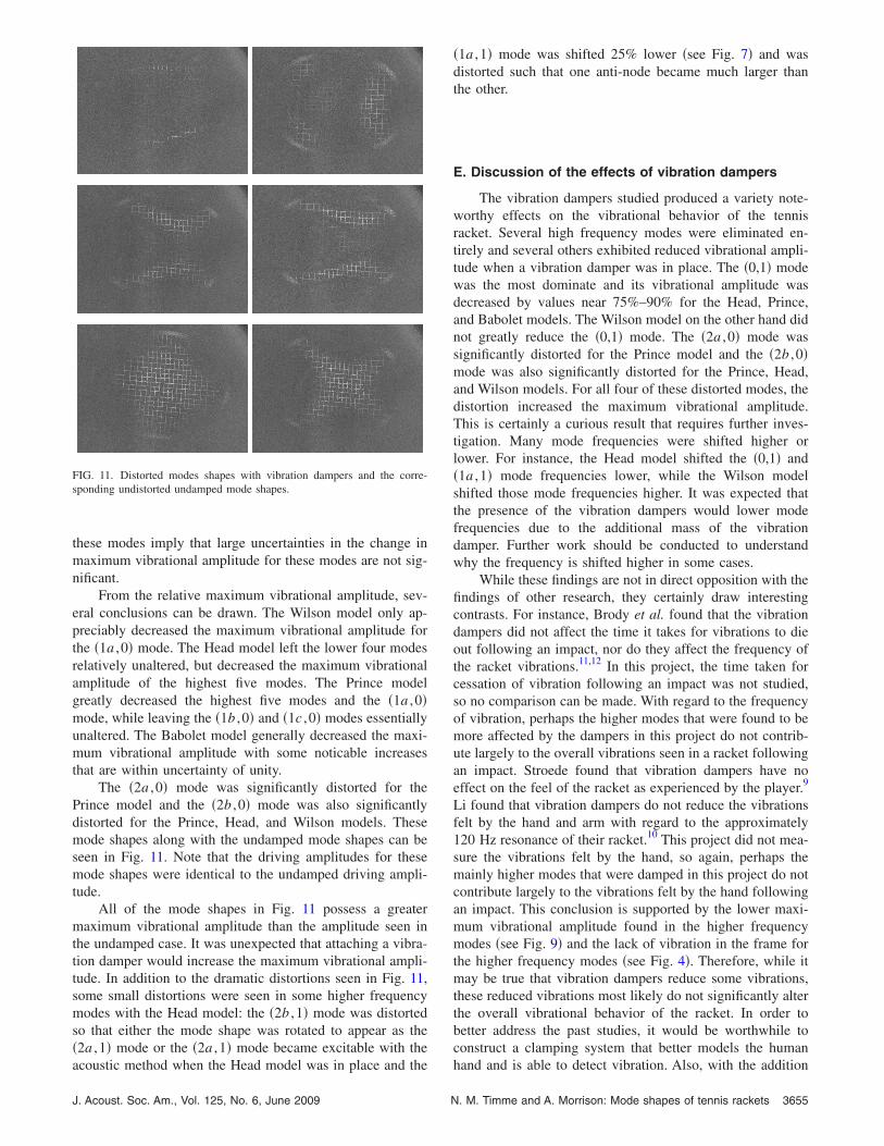
The �2a ,0� mode was significantly distorted for thePrince model and the �2b ,0� mode was also significantlydistorted for the Prince, Head, and Wilson models. Thesemode shapes along with the undamped mode shapes can beseen in Fig. 11. Note that the driving amplitudes for thesemode shapes were identical to the undamped driving ampli-tude.
All of the mode shapes in Fig. 11 possess a greatermaximum vibrational amplitude than the amplitude seen inthe undamped case. It was unexpected that attaching a vibra-tion damper would increase the maximum vibrational ampli-tude. In addition to the dramatic distortions seen in Fig. 11,some small distortions were seen in some higher frequencymodes with the Head model: the �2b ,1� mode was distortedso that either the mode shape was rotated to appear as the�2a ,1� mode or the �2a ,1� mode became excitable with the
FIG. 11. Distorted modes shapes with vibration dampers and the corre-sponding undistorted undamped mode shapes.
acoustic method when the Head model was in place and the
J. Acoust. Soc. Am., Vol. 125, No. 6, June 2009 N
�1a ,1� mode was shifted 25% lower �see Fig. 7� and wasdistorted such that one anti-node became much larger thanthe other.
E. Discussion of the effects of vibration dampers
The vibration dampers studied produced a variety note-worthy effects on the vibrational behavior of the tennisracket. Several high frequency modes were eliminated en-tirely and several others exhibited reduced vibrational ampli-tude when a vibration damper was in place. The �0,1� modewas the most dominate and its vibrational amplitude wasdecreased by values near 75%–90% for the Head, Prince,and Babolet models. The Wilson model on the other hand didnot greatly reduce the �0,1� mode. The �2a ,0� mode wassignificantly distorted for the Prince model and the �2b ,0�mode was also significantly distorted for the Prince, Head,and Wilson models. For all four of these distorted modes, thedistortion increased the maximum vibrational amplitude.This is certainly a curious result that requires further inves-tigation. Many mode frequencies were shifted higher orlower. For instance, the Head model shifted the �0,1� and�1a ,1� mode frequencies lower, while the Wilson modelshifted those mode frequencies higher. It was expected thatthe presence of the vibration dampers would lower modefrequencies due to the additional mass of the vibrationdamper. Further work should be conducted to understandwhy the frequency is shifted higher in some cases.
While these findings are not in direct opposition with thefindings of other research, they certainly draw interestingcontrasts. For instance, Brody et al. found that the vibrationdampers did not affect the time it takes for vibrations to dieout following an impact, nor do they affect the frequency ofthe racket vibrations.11,12 In this project, the time taken forcessation of vibration following an impact was not studied,so no comparison can be made. With regard to the frequencyof vibration, perhaps the higher modes that were found to bemore affected by the dampers in this project do not contrib-ute largely to the overall vibrations seen in a racket followingan impact. Stroede found that vibration dampers have noeffect on the feel of the racket as experienced by the player.9
Li found that vibration dampers do not reduce the vibrationsfelt by the hand and arm with regard to the approximately120 Hz resonance of their racket.10 This project did not mea-sure the vibrations felt by the hand, so again, perhaps themainly higher modes that were damped in this project do notcontribute largely to the vibrations felt by the hand followingan impact. This conclusion is supported by the lower maxi-mum vibrational amplitude found in the higher frequencymodes �see Fig. 9� and the lack of vibration in the frame forthe higher frequency modes �see Fig. 4�. Therefore, while itmay be true that vibration dampers reduce some vibrations,these reduced vibrations most likely do not significantly alterthe overall vibrational behavior of the racket. In order tobetter address the past studies, it would be worthwhile toconstruct a clamping system that better models the human
hand and is able to detect vibration. Also, with the addition. M. Timme and A. Morrison: Mode shapes of tennis rackets 3655

of a high speed camera to the SPI system, the vibrations of atennis racket following an impact with a tennis ball could beobserved and studied using SPI.
In connection with the discussion in Sec. IV A, it isinteresting to note the distortion of the �2a ,0� mode by thePrince model and the �2b ,0� mode by the Prince, Head, andWilson models. All of these distortions remove a node fromthe center of the racket near the supposed sweet spot. If thesweet spot is indeed the result of the presence of the nodes inthe center of the racket, then these models of vibration damp-ers may actually weaken the sweet spot.
VI. CONCLUSIONS
It has been demonstrated that the vibrational behavior ofa tennis racket can be studied using SPI. As a result of thisstudy, the first 12 mode shapes of a tennis racket have beenshown and analyzed. In addition, the SPI system was utilizedto examine the effects of vibration dampers on the vibra-tional behavior of a tennis racket. It was found that the vi-bration dampers do reduce vibrations for some mode fre-quencies, though these effects may not be significant in play.In addition, the vibration dampers were observed to altersome mode frequencies and mode shapes.
ACKNOWLEDGMENTS
We would like to thank the IWU students Tom Traynor,Alex Boecher, Sawyer Campbell, and Kristy Streu for theirefforts in constructing the SPI system and LABVIEW pro-grams. In addition, we would like to thank Dr. ThomasMoore of Rollins College for his advice about the SPI sys-
tem setup.3656 J. Acoust. Soc. Am., Vol. 125, No. 6, June 2009
1J. Kotze, “The role of the racket in high speed tennis serves,” Sports Eng.3, 67 �2000�.
2R. Cross, “Center of percussion of hand-held implements,” Am. J. Phys.72, 622 �2004�.
3R. Cross, “The sweet spots of a tennis racket,” Sports Eng. 1, 63 �1998�.4H. Brody, “The physics of tennis: III the ball-racket interaction,” Am. J.Phys. 65, 981 �1997�.
5H. Brody, “The physics of the tennis racket: II the “sweet spot”,” Am. J.Phys. 49, 816 �1981�.
6S. J. Haake, “The dynamic impact characteristics of tennis balls withtennis rackets,” J. Sports Sci. 21, 839 �2003�.
7J. E. Oh, “A study on the dynamic characteristics of tennis racket bymodal analysis,” Bull. JSME 29, 2228 �1986�.
8M. Brannigan, “Mathematical modeling and simulation of a tennis racket,”Med. Sci. Sports Exercise 13, 44 �1981�.
9C. L. Stroede, “The effect of tennis racket string vibration dampers onracket handle vibrations and discomfort following impacts,” J. Sports Sci.17, 379 �1999�.
10F. X. Li, “String vibration dampers do not reduce racket frame vibrationtransfer to the forearm,” J. Sports Sci. 22, 1041 �2004�.
11H. Brody, “Vibration damping of tennis rackets,” Int. J. of Sports Biome-chanics 5, 451 �1989�.
12H. Brody, R. Cross, and C. Lindsey, The Physics and Technology of Tennis�Racquet Tech Publishing, Solana Beach, CA, 2002�.
13O. J. Lokberg, “Use of chopped laser light in electronic speckle patterninterferometry,” Appl. Opt. 18, 2377 �1979�.
14O. J. Lokberg, “Interferometric comparison of displacements by electronicspeckle pattern interferometry,” Appl. Opt. 20, 2630 �1981�.
15T. R. Moore, “A simple design for an electronic speckle pattern interfer-ometer,” Am. J. Phys. 72, 1380 �2004�.
16T. R. Moore, “Interferometric studies of a piano soundboard,” J. Acoust.Soc. Am. 119, 1783 �2006�.
17G. O. Rosvold, “Effect and use of exposure control in vibration analysisusing tv holography,” Appl. Opt. 32, 684 �1993�.
18T. R. Moore, “Imaging vibrations and flow using electronic speckle patterninteferometry �a�,” J. Acoust. Soc. Am. 120, 3364 �2006�.
19H. Brody, “Models of tennis racket impacts,” Int. J. of Sports Biomechan-ics 3, 293 �1987�.
20R. Cross, “The dead spot of a tennis racket,” Am. J. Phys. 65, 754 �1997�.
N. M. Timme and A. Morrison: Mode shapes of tennis rackets