bacproject constructionkground to the …eisdocs.dsdip.qld.gov.au/sunshine coast airport...
TRANSCRIPT

CONTENTS
5.1 Construction methodology ..........................................100 5.1.1 Construction schedule ........................................... 100 5.1.2 Workforce .................................................................... 100 5.1.3 Hours of work .............................................................101
5.2 Pre-construction works ................................................ 101
5.3 Package 1: Civil works .................................................. 101 5.3.1 Stage 1: Construction compound and
Finland Road upgrade ............................................101 5.3.2 Stage 2: Preliminary works .................................. 103 5.3.2.1 Fencing.......................................................... 103 5.3.2.2 Internal access roads ............................. 103 5.3.2.3 Site clearing ................................................ 103 5.3.2.4 Relocation of navigation aids
and helipads ............................................... 103 5.3.2.5 Acid sulphate soil treatment pads
and stockpile areas ................................. 103 5.3.3 Stage 3: Major drainage ....................................... 103 5.3.4 Stage 4: Reclamation bunds and tailwater
polishing pond........................................................... 107 5.3.5 Waste generation and management
for Package 1 ............................................................ 107
5.4 Package 2: Dredging and reclamation .................... 110 5.4.1 Dredging .......................................................................110 5.4.1.1 Dredge footprint .........................................110 5.4.1.2 Dredging footprint bathymetry ............110 5.4.1.3 Geotechnical and geophysical
information ...................................................110 5.4.1.4 Dredge vessel selection .........................110 5.4.1.5 Dredging operation ..................................115 5.4.1.6 Vessel navigation .......................................118 5.4.2 Sand delivery ..............................................................118 5.4.2.1 Overview ........................................................118
5.4.2.2 Pump-out location ....................................118 5.4.2.3 Temporary pump-out mooring
and floating pipeline .................................121 5.4.2.4 Submerged pipeline to shore ..............121 5.4.2.5 Pipeline from David Low Way to
placement site ........................................... 124 5.4.2.6 Booster pump station ............................ 126 5.4.2.7 Sand delivery production ..................... 127 5.4.3 Sand placement ....................................................... 127 5.4.3.1 Placement site and levels ..................... 127 5.4.3.2 Placement methodology ....................... 127 5.4.3.3 Bunds ............................................................ 130 5.4.3.4 Capping ........................................................ 130 5.4.3.5 Tailwater management ........................... 130 5.4.3.6 Pipeline removal ....................................... 132 5.4.3.7 Consolidation period .............................. 132 5.4.3.8 Sand trimming ........................................... 132 5.4.3.9 Decommissioning polishing pond .... 132 5.4.4 Waste generation and management
for Package 2 ............................................................ 132
5.5 Package 3: Runway, taxiways and aprons ............134 5.5.1 Material storage and production ....................... 134 5.5.2 Pavement staging .................................................... 134 5.5.3 Drainage ....................................................................... 134 5.5.4 Sub-grade construction ......................................... 134 5.5.5 Flexible pavements .................................................. 134 5.5.6 Electrical installations.............................................. 134 5.5.7 Pavement markings ................................................. 135 5.5.8 Perimeter road and fence ..................................... 135 5.5.9 Decommission construction site ....................... 135 5.5.10 Commission runway ............................................... 135 5.5.11 Waste generation and management
for Package 3 ............................................................ 135
A5-98 SUNSHINE COAST AIRPORT EXPANSION PROJECT
A5 BACkGROunD TO The PROjeCT
PROJECT CONSTRUCTION
5.6 Package 4: Building works .......................................... 137 5.6.1 Terminal upgrade ..................................................... 137 5.6.2 Air Traffic Control tower and Aviation Rescue
and Fire Fight Service facility .............................. 137 5.6.3 Waste generation and management
for Package 4 .......................................................... 137
FIGURES
5.1a: Construction package phasing and estimated costs ....................................................................... 1005.1b: Manning and vehicle chart for the construction period ................................................................1015.3a Finland Road upgrade and construction compound ................................................................................. 1025.3b: Temporary fence arrangements and VOR
and helipads relocations ..................................................... 1045.3c: On-site construction access roads and
clearing areas ........................................................................... 1055.3d: ASS treatment pads and stockpile areas.................... 1065.3e: Major drainage layout ........................................................... 1085.3f: Reclamation bund and tailwater polishing pond ..... 1095.4a: Sand extraction area: Spitfire Realignment Channel ............................................1115.4b: Indicative dredge footprint based on 2010
seabed bathymetry: 300 m wide channel to depth of approximately -11.55 m CD .............................112
5.4c: Indicative dredge footprint for dredging undertaken after PBPL sand allocation extracted: 500 m wide channel to approximately 17.05 m CD ..................................................113
5.4d: Indicative navigation route for the dredge vessel .....1185.4e Sand delivery pipeline alignment .....................................1195.4f: Indicative location of the dredge vessel
and pipeline during pump-out ......................................... 1205.4g: Schematic of typical configuration of the
pipeline and dredger at rest and during sand pumping .......................................................................... 122
5.4h: Indicative areas for construction compound and assembly at Marcoola Beach .................................. 123
5.4i: Cross section of the pipeline assembly at the beach .............................................................................. 123
5.4j: Indicative pipeline alignment and constraints ........... 1255.4k: Typical section of sand delivery pipeline corridor ... 1255.4l: Booster pump station under construction.
Photo shows bypass line, valve set, sand pump and frame for housing .......................................................... 127
5.4m: A booster station during the establishment stage. The pump and engine are mounted on two skid pads .................................................................... 127
5.4n: Preliminary reclamation levels .......................................... 1295.4o: Reclamation sequence .........................................................1315.4p: Sand rehandling ...................................................................... 133
5.5a: Pavement staging and airside perimeter fence works ............................................................................... 136
TABLES
5.1a: Anticipated workforce for each works package ...... 1005.3a: estimated waste generation and
proposed management ....................................................... 1075.4a: Summary assessment of TShD sizes ...........................1165.4b: Typical dredging and pump-out cycle times1 ............1175.4c: Operational details of the booster pump station ..... 1285.4d: Typical polishing pond and
tailwater characteristics ....................................................... 1325.4e: estimated waste generation and
proposed management ....................................................... 1345.5a: estimated waste generation and
proposed management ....................................................... 1355.6a: estimated waste generation and
proposed management ....................................................... 137
1 The estimated cycle times and activity durations exclude delays due to extreme metocean conditions, equipment breakdowns, scheduled maintenance, and vessel traffic delays.
A5-99environmental impact statement

5.1 CONSTRUCTION METhOdOLOGy
5.1.1 Construction schedule
The construction works for the Sunshine Coast Airport (SCA) expansion Project (the Project) have been divided into four packages based on program and activities as follows:
y Package 1: Civil works
− Stage 1: Construction compound and upgrade of Finland Road
− Stage 2: Preliminary works
− Stage 3: Major drainage
− Stage 4: Dredge bunds and polishing pond
y Package 2: dredging and reclamation
− Stage 5: Mobilisation and establishment of sand delivery pipeline and dredge pump out point
y Package 3: Runway, taxiway and apron construction
− Stage 6: Construction of Runway (RWY) 13/31
− Stage 7: Final connection of RWY 13/31 to RWY 18/36
y Package 4: Building works
The proposed construction program and the estimated construction and other costs are outlined in Figure 5.1a.
5.1.2 Workforce
The anticipated workforce for each works package is shown in Table 5.1a.
The workforce will consist of a variety of employee types, including permanent, contract, full-time and part-time personnel.
Figure 5.1a: Construction package phasing and estimated costs
Construction Package
2016 2017 2018 2019 2020 Package Construction
Cost ($)1 2 3 4 1 2 3 4 1 2 3 4 1 2 3 4 1 2 3 4
Package 1: civil works 34,265,000
Package 2: dredging and reclamation 70,580,000
Package 3: runway, taxiways and aprons 68,910,000
Package 4: building works 6,410,000
Commissioning
Operational ◆
Total Construction Cost 180,165,000
Owner’s Costs 52,455,000
Contingency 58,155,000
escalation 56,225,000
TOTAL TuRn OuT COST ($) 347,000,000
Note: Blue indicates dredging and sand delivery phase
Table 5.1a: Anticipated workforce for each works package (anticipated direct employment numbers)
Works Package Supervision and Professionals Labour (Skilled and Unskilled)
Package 1: civil works 10 30
Package 2: dredging & reclamation 10 10
Package 3: runway, taxiway and apron construction 15 45
Package 4: building works 10 40
A5-100
background to the project
PROJECT CONSTRUCTIONA5
SunShIne coaSt aIrport eXpanSIon project

Figure 5.1b: Manning and vehicle chart for the construction period
80
70
60
50
40
30
20
10
0
year 1 year 2 year 3 year 4
Total manning 40 60 70 35
Light vehicles 10 10 10 10
heavy vehicles 23 23 20 17
Total vehicles 33 33 30 27
It is expected that Package 3: runway, taxiway and apron construction will require the largest workforce of the construction packages.
It is anticipated that the workforce will be local, and no on-site worker accommodation is proposed.
The manning and vehicle chart for the proposed works is shown in Figure 5.1b, indicating a peak workforce of 70 people in the third year of construction.
5.1.3 hours of work
Typical construction hours will be between 7.00 a.m. and 6.00 p.m. Monday to Friday, with some seasonal adjustment to account for reduced daylight hours in winter. Deliveries of plant and materials may occur outside these hours because of transport constraints imposed for low loader or wide load truck movements.
Delivery of sand to the site from the dredge vessel will occur on a 24/7 basis for up to 14 weeks during the winter of the second year of construction (Package 2).
5.2 PRE-CONSTRUCTION WORkS
no land needs to be acquired to allow for construction of the Project.
SCA will negotiate with eneRGeX to ensure that the existing overhead power lines that traverse the site will be realigned and put underground prior to runway construction works commencing (see Section A4.16).
5.3 PACkAGE 1: CIvIL WORkS
5.3.1 Stage 1: Construction compound and Finland Road upgrade
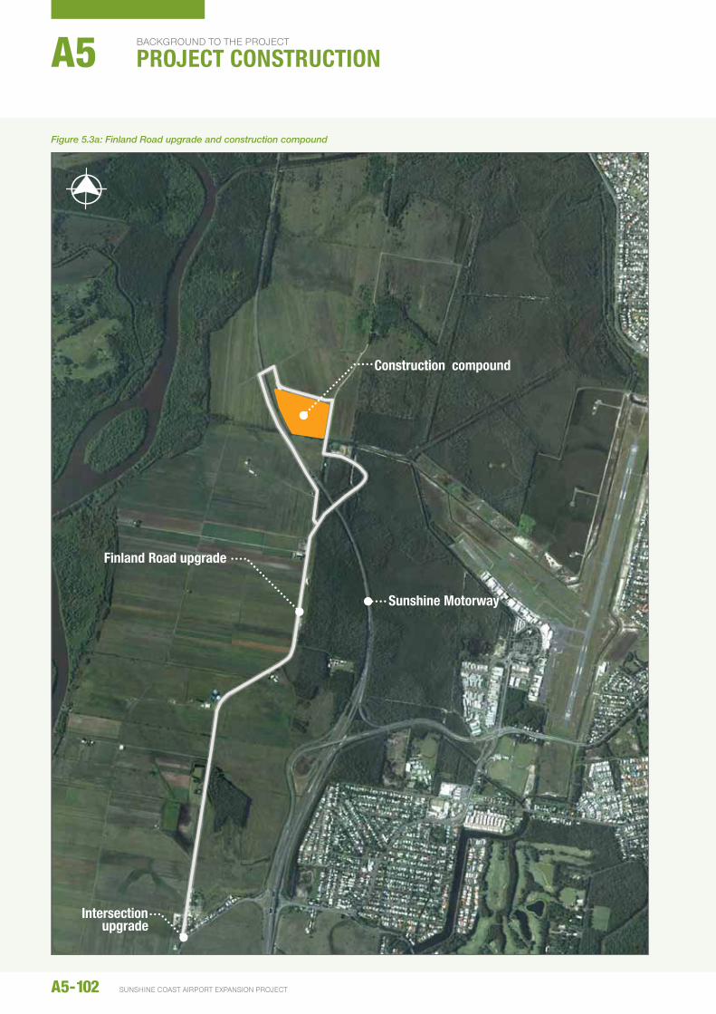
Initial preparatory works will include establishment of a construction compound and upgrades to Finland Road to provide access to the construction compound and works areas, as shown in Figure 5.3a.
It is proposed to provide access to the construction site via Finland Road from David Low way to allow existing airport traffic using Airport Drive and airport operations to remain unaffected by construction traffic.
The existing overpass on Finland Road that crosses the Sunshine Motorway and an existing underpass will be used to provide a circular traffic flow. The underpass is subject to flooding and will be upgraded to improve access in wet weather.
The upgrade is anticipated to include a signalised intersection with David Low Way to ensure safe traffic conditions, particularly with the movement of heavy vehicles in and out of the site. Finland Road will be widened and paved along its full length to provide all weather access to the construction site, while maintaining the road for local residents.
The underpass was constructed to provide access for properties bisected by the Sunshine Motorway, and is expected to be suitable for construction vehicle access, with the exception of high and wide vehicles which will need to use the Finland Road overpass under the necessary escort arrangements.
Construction year
Num
ber
A5-101environmental impact statement
A5-102 SUNSHINE COAST AIRPORT EXPANSION PROJECT
BACkGROunD TO The PROjeCT
PROJECT CONSTRUCTIONA5
Intersection upgrade
Finland Road upgrade
Sunshine Motorway
Construction compound
Figure 5.3a: Finland Road upgrade and construction compound
The majority of construction traffic will enter the site via the underpass and exit via the overpass. This would allow the safe and free movement of traffic where the entering and exiting traffic meeting on Finland Road, without needing to cross the path of oncoming vehicles. Additionally, the tight bend and steep downgrade on the eastern side of the Finland Road overpass make this an undesirable approach for heavily laden construction traffic, and therefore this approach would only be used for vehicles that cannot use the underpass because of height restrictions.
The construction compound will be located within an existing 6.5 ha cleared part of the site, as shown in Figure 5.3a. A 4 ha fenced hardstand area will be established at the construction compound, which will require approximately 0.5 m of fill to make it suitable for use in wet weather. The construction compound will be used by multiple contractors over the course of construction of the new runway. The location of the construction compound was chosen for its proximity to the construction site and existing trunk services, including water, sewer and power. An approved connection to the trunk utilities will be established as part of the construction compound works.
The construction compound would include suitable areas and facilities for the storage and handling of dangerous or hazardous goods as required. Transport, handling and storage will be undertaken in accordance with relevant legislation, codes and standards including the Australian Dangerous Goods code.
5.3.2 Stage 2: Preliminary works
5.3.2.1 Fencing
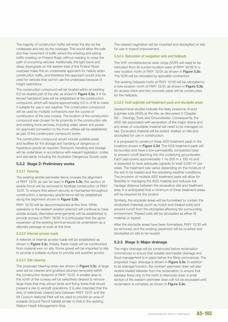
The existing airside perimeter fence crosses the alignment of RWY 13/31, as can be seen in Figure 5.3b; this section of airside fence will be removed to facilitate construction of RWY 13/31. To ensure that airport security is maintained throughout construction, a temporary airside fence will be established along the alignment shown in Figure 5.3b.
RWY 12/30 will be decommissioned at this time. While operators in the western aviation precinct will continue to have airside access, alternative arrangements will be established to provide access to RWY 18/36. It is anticipated that the apron expansion at the existing terminal would be undertaken as a discrete package of work at this time.
5.3.2.2 Internal access roads
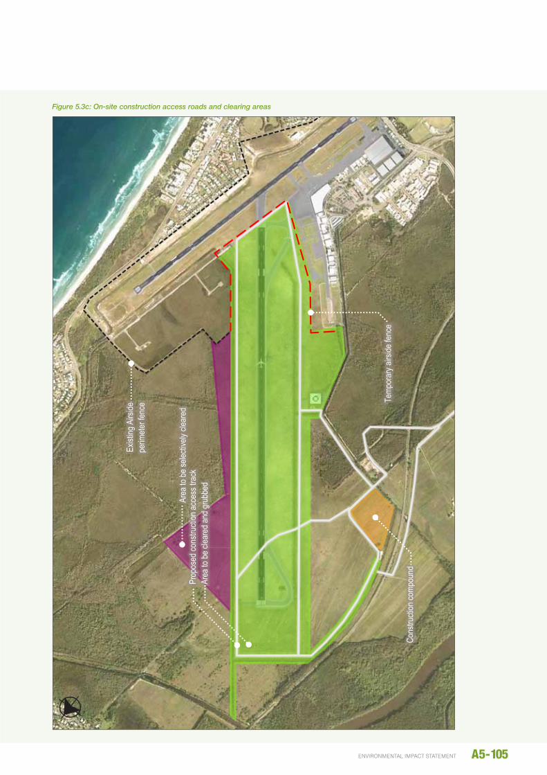
A network of internal access roads will be established as shown in Figure 5.3c. Initially, these roads will be constructed from material won on site. Some gravel will be imported to site to provide a suitable surface to provide wet weather access.
5.3.2.3 Site clearing
The proposed clearing areas are shown in Figure 5.3c. A large area will be cleared and grubbed (stumps removed) within the construction footprint of RWY 13/31. A smaller area to the north of the runway will be selectively cleared to remove large trees that may attract birds and flying-foxes that would present a risk to aircraft operations. It is also intended that the strip of selectively cleared land between RWY 13/31 and the Mt Coolum national Park will be used to provide an area of suitable Ground Parrot habitat similar to that in the existing Wallum heath Management Area.
The cleared vegetation will be mulched and stockpiled on site for use in topsoil improvement.
5.3.2.4 Relocation of navigation aids and helipads
The VhF omnidirectional radio range (VOR) will need to be relocated from its current location west of RWY 18/36 to a new location north of RWY 13/31, as shown in Figure 5.3b. The VOR will be relocated by specialist contractors.
The existing helipads north of RWY 12/30 will be relocated to a new location north of RWY 13/31, as shown in Figure 5.3b. An access track and two concrete pads will be constructed for the helipads.
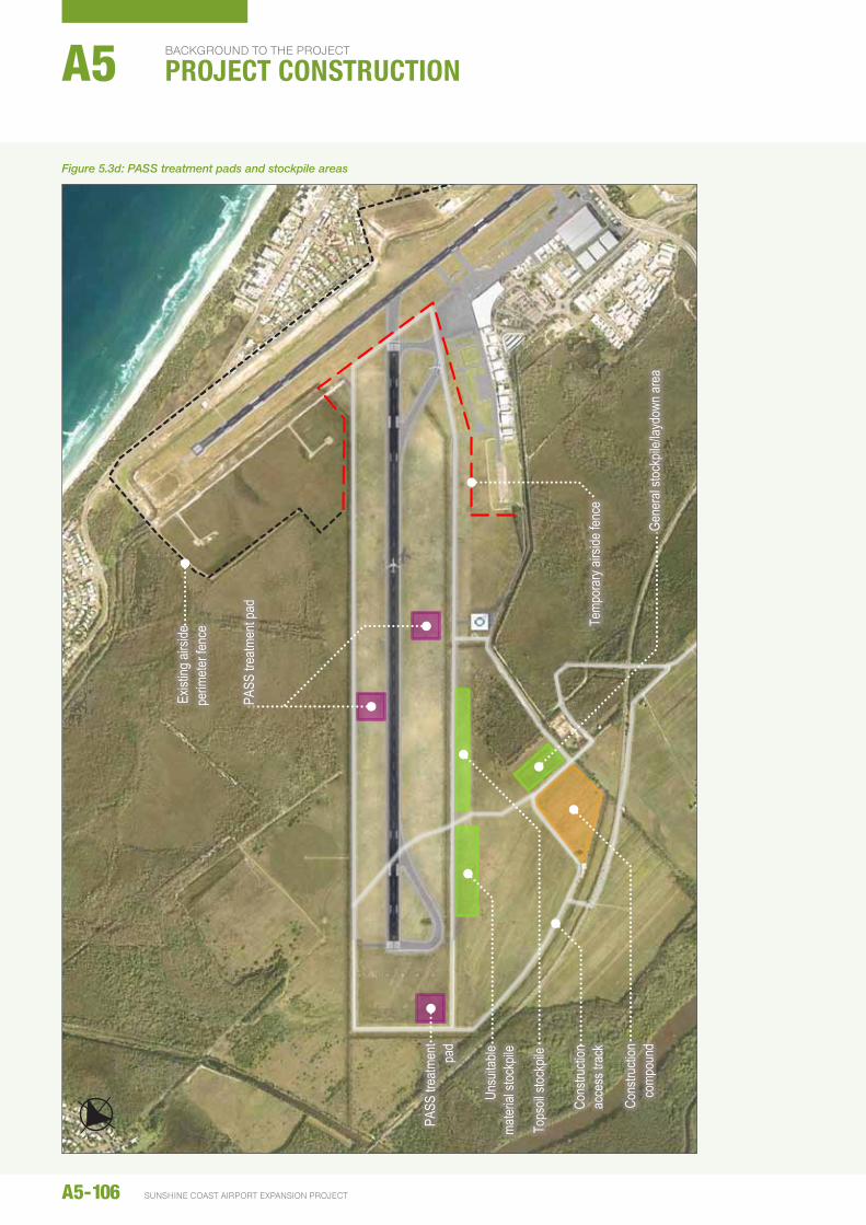
5.3.2.5 Acid sulphate soil treatment pads and stockpile areas
Geotechnical studies indicate the likely presence of acid sulphate soils (ASS) at the site, as discussed in Chapter B3 – Geology, Soils and Groundwater. Consequently, the ASS risk associated with excavation of the major drains and any areas of unsuitable material will need to be managed on site. excavated material will be tested, treated on site and stockpiled for use in construction.
It is proposed to construct three ASS treatment pads in the locations shown in Figure 5.3d. The ASS treatment pads will be bunded and have a low-permeability compacted base to prevent runoff leaching into the underlying groundwater. each pad covers approximately 1 ha (100 m x 100 m) and is expected to have adequate capacity to treat 3,000 m3 per week. The treatment rate varies depending on the moisture of the soil to be treated and the prevailing weather conditions. The provision of multiple ASS treatment pads will allow for flexibility in managing the ASS material and reduces the haulage distance between the excavation site and treatment area. It is anticipated that a minimum of three treatment areas will be required for the project.
Similarly, the stockpile areas will be formalised to contain the stockpiled materials (such as mulch and treated soils) and prevent runoff from the stockpiles affecting the surrounding environment. Treated soils will be stockpiled as either fill material or topsoil.
After the stockpile areas have been formalised, RWY 12/30 will be removed, and the existing pavement will be crushed and stockpiled on site to be reused.
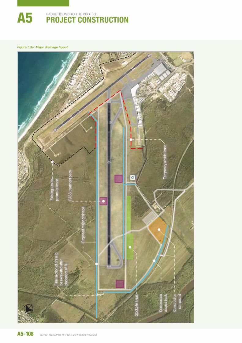
5.3.3 Stage 3: Major drainage
The major drainage will be constructed before reclamation commences to ensure that suitable stormwater drainage and flood management is in place before the filling commences. The proposed major drainage is shown in Figure 5.3e. In addition to its drainage function, the northern perimeter drain will also receive treated tailwater from the reclamation; to ensure that tailwater flows only to the north to Marcoola drain, a small section of the western perimeter drain will not be excavated until reclamation is complete, as shown in Figure 5.3e.
A5-103environmental impact statement
A5-104 SUNSHINE COAST AIRPORT EXPANSION PROJECT
bACkgROUNd TO THE PROJECT
PROJECT CONSTRUCTIONA5
19 J
uly
2014
\\a
ubne
1fp0
03\p
roje
cts\
proj
ects
\602
4859
4\6.
dra
ft do
cs\6
.1 re
ports
\resc
ope
repo
rts\0
02_c
onst
ruct
ion
met
hodo
logy
\imag
es\c
onst
ruct
ion
imag
es_2
0140
711.
docx
3
of 1
6
Figu
re 5
.4b:
Tem
pora
ry fe
nce
arra
ngem
ents
and
VO
R a
nd h
elip
ads
relo
catio
n
Finlan
d Roa
d upg
rade
Exist
ing ai
rside
perim
eter
fence
to re
main
Exist
ing ai
rside
perim
eter
fence
to be
remo
ved
Cons
tructi
on co
mpou
nd
Temp
orar
y airs
ide fe
nce
Reloc
ated V
HF om
nidire
ction
al ra
dar
(VOR
) nav
igatio
n aid
(afte
r clea
ring)
Reloc
ated h
elipa
ds (a
fter c
learin
g)
Figure 5.3b: Temporary fence arrangements and VOR and helipads relocation
A5-105environmental impact statement
19 J
uly
2014
\\a
ubne
1fp0
03\p
roje
cts\
proj
ects
\602
4859
4\6.
dra
ft do
cs\6
.1 re
ports
\resc
ope
repo
rts\0
02_c
onst
ruct
ion
met
hodo
logy
\imag
es\c
onst
ruct
ion
imag
es_2
0140
711.
docx
4
of 1
6
Figu
re 5
4c: O
n-si
te c
onst
ruct
ion
acce
ss ro
ads
and
clea
ring
foot
prin
t
Prop
osed
cons
tructi
on ac
cess
trac
k
Exist
ing A
irside
pe
rimete
r fen
ce Te
mpor
ary a
irside
fenc
e
Area
to be
clea
red a
nd gr
ubbe
d
Area
to be
selec
tively
clea
red
Cons
tructi
on co
mpou
nd
Figure 5.3c: On-site construction access roads and clearing areas
A5-106 SUNSHINE COAST AIRPORT EXPANSION PROJECT
bACkgROUNd TO THE PROJECT
PROJECT CONSTRUCTIONA5
19 J
uly
2014
\\a
ubne
1fp0
03\p
roje
cts\
proj
ects
\602
4859
4\6.
dra
ft do
cs\6
.1 re
ports
\resc
ope
repo
rts\0
02_c
onst
ruct
ion
met
hodo
logy
\imag
es\c
onst
ruct
ion
imag
es_2
0140
711.
docx
5
of 1
6
Figu
re 5
.4d:
Sto
ckpi
le a
reas
and
PA
SS
trea
tmen
t pad
s
Cons
tructi
on
acce
ss tr
ack
Exist
ing ai
rside
pe
rimete
r fen
ce Te
mpor
ary a
irside
fenc
e
Cons
tructi
on
comp
ound
Un
suita
ble
mater
ial st
ockp
ile
Tops
oil st
ockp
ile
PASS
trea
tmen
t pad
PASS
trea
tmen
t pa
d
Gene
ral s
tockp
ile/la
ydow
n are
a
Figure 5.3d: PASS treatment pads and stockpile areas

The major drainage will be excavated progressively, and the excavated material will be transported to the nearest ASS treatment pad for treatment and reuse on site. When the major drains have been excavated, any existing drains within the reclamation area will be filled with treated material or sand to ensure an even surface for installation of the geosynthetic liner (refer Section 5.4.3.2).
A number of banks of large culverts will be established in the northern and western perimeter drains to provide access across the channels for maintenance and emergency response.
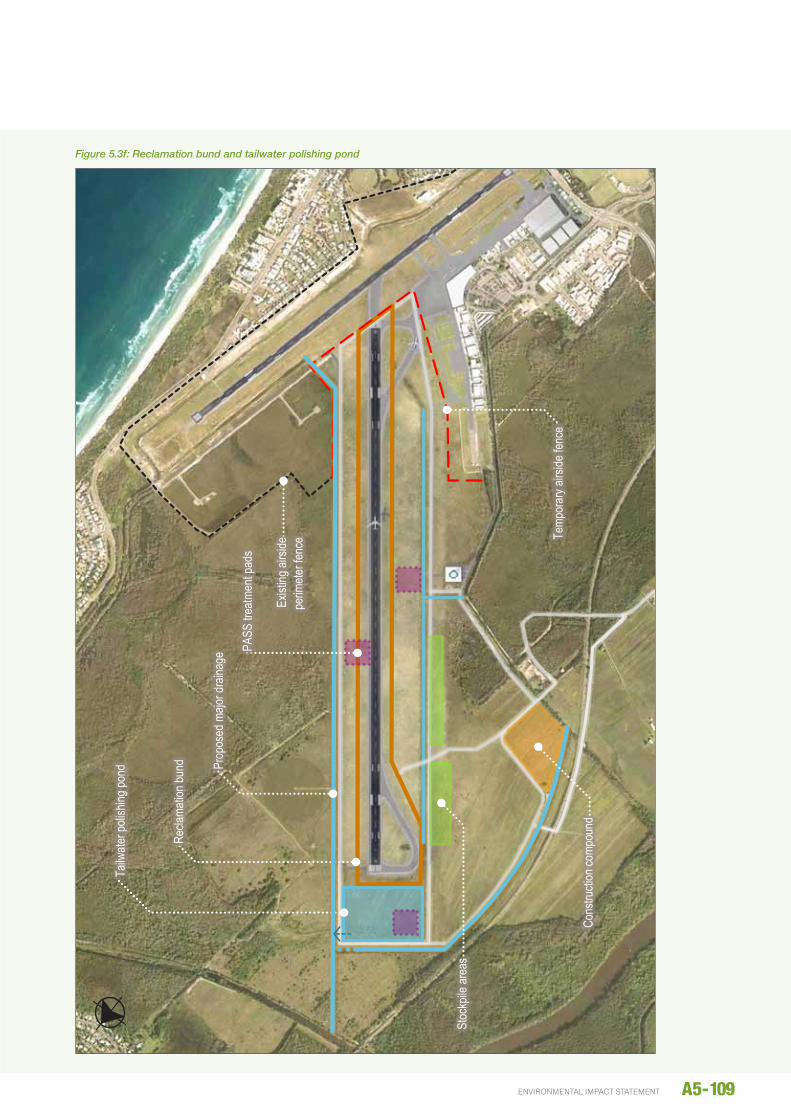
5.3.4 Stage 4: Reclamation bunds and tailwater polishing pond
In preparation for the reclamation works, a perimeter bund and tailwater polishing pond will be established at the site.
The reclamation area will be surrounded by a water retaining perimeter bund, which is to be constructed with materials suitable for the purpose.
Bunds constructed of non-cohesive or high permeability materials would be lined with heavy-duty plastic sheeting to contain the tailwater from the sand delivery, and to protect the bunds from erosion and scour.
The top of the final bund is expected to be at approximately 4.5 m AhD, with the bund height ranging from around 1 m to 3.5 m. The bund profile will be dependent on the material used for construction, with the batter slope appropriate to maintain stability of the bund.
It is anticipated that initial construction of the perimeter bund would be to a low height, approximately 1 m. This initial bund would be constructed from on-site materials where they are available, although imported materials may be required. Once sand delivery commences, the perimeter bund height would be raised using sand pumped to site (refer Section 5.4.3.3). On completion of the perimeter bund, the ASS treatment pads will be decommissioned.
Three walls of the polishing pond must be constructed of low permeability material to ensure it is capable of safely storing the tailwater from the reclamation area.
The eastern wall, where the polishing pond ties into the reclamation area, will be constructed in the same way as the perimeter bund. The polishing pond wall will be constructed of imported material with suitable properties. The polishing pond will not be lined.
A preliminary arrangement for the perimeter bund and polishing pond is shown in Figure 5.3f.
5.3.5 Waste generation and management for Package 1
The estimated amount and proposed management response for wastes generated during Package 1 works are outlined in Table 5.3a.
Table 5.3a: Estimated waste generation and proposed management
Waste Type Generating Activities Approximate Amount Management Approach
unexploded ordnance Site preparation unknown (minor amounts)
Detected and disposed off-site by specialist personnel
Cleared vegetation Clearing and grubbing 40 m3 Woody vegetation chipped for reuse on site
100 m3 Material unsuitable for chipping disposed off-site at a licenced facility
unsuitable material (i.e. soft or contaminated soils in the construction site)
Site preparation unknown (minor amounts)
unsuitable material disposed off-site at a licenced facility
ASS material excavation 175,000 m3 Material to be treated and reused on site
Pavement material and other aggregate
Road upgrade works, internal road construction, hardstand construction, demolition of RWY 12/30
150 t Material to be stockpiled on site for reuse
General construction waste
Compound establishment, fencing, services relocations, used erosion and sediment control materials
2,060 t Disposed off-site or recycled as appropriate by specialist contractors
Concrete Drain realignment east of RWY 18/36 40 t Crushed and stockpiled on site for reuse
A5-107environmental impact statement
A5-108 SUNSHINE COAST AIRPORT EXPANSION PROJECT
bACkgROUNd TO THE PROJECT
PROJECT CONSTRUCTIONA5
19 J
uly
2014
\\a
ubne
1fp0
03\p
roje
cts\
proj
ects
\602
4859
4\6.
dra
ft do
cs\6
.1 re
ports
\resc
ope
repo
rts\0
02_c
onst
ruct
ion
met
hodo
logy
\imag
es\c
onst
ruct
ion
imag
es_2
0140
711.
docx
6
of 1
6
Figu
re 5
.4e:
Maj
or d
rain
age
Cons
tructi
on
acce
ss tr
ack
Exist
ing ai
rside
pe
rimete
r fen
ce Te
mpor
ary a
irside
fenc
e
Prop
osed
majo
r dra
inage
Final
secti
on of
drain
to
be ex
cava
ted af
ter
place
ment
of fill
Cons
tructi
on
comp
ound
St
ockp
ile ar
eas
PASS
trea
tmen
t pad
s
Figure 5.3e: Major drainage layout
A5-109environmental impact statement
19 J
uly
2014
\\a
ubne
1fp0
03\p
roje
cts\
proj
ects
\602
4859
4\6.
dra
ft do
cs\6
.1 re
ports
\resc
ope
repo
rts\0
02_c
onst
ruct
ion
met
hodo
logy
\imag
es\c
onst
ruct
ion
imag
es_2
0140
711.
docx
7
of 1
6
Figu
re 5
.4f:
Rec
lam
atio
n bu
nd a
nd ta
ilwat
er p
olis
hing
pon
d
Exist
ing ai
rside
pe
rimete
r fen
ce
Tailw
ater p
olish
ing po
nd
Recla
matio
n bun
d
Temp
orar
y airs
ide fe
nce
Cons
tructi
on co
mpou
nd
PA
SS tr
eatm
ent p
ads
Stoc
kpile
area
s
Prop
osed
majo
r dra
inage
Figure 5.3f: Reclamation bund and tailwater polishing pond
5.4 PACkAGE 2: dREdGING ANd RECLAMATION
5.4.1 dredging
The Project requires approximately 1.1 M m3 of fill material for construction of the new runway. It is proposed to source sand from the Spitfire Realignment Channel using a dredger and transporting to a pump-out site located offshore from the SCA. The sand will be hydraulically pumped ashore via a delivery pipeline to the sand placement area.
This section discusses the methodology for undertaking the dredging works and the rationale for the selecting the reference dredge vessel.
5.4.1.1 Dredge footprint
Options and chosen site
A number of sand sources were considered for the Project, as discussed in Chapter A3 – Options and Alternatives.
Spitfire Realignment Channel
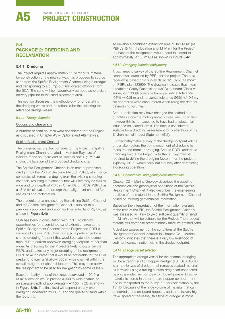
The preferred sand extraction area for the Project is Spitfire Realignment Channel, located in Moreton Bay east of Woorim at the southern end of Bribie Island. Figure 5.4a shows the location of the proposed dredging site.
The Spitfire Realignment Channel is an area of proposed dredging by the Port of Brisbane Pty Ltd (PBPL), which once complete, will remove a dogleg from the existing shipping channels, resulting in a channel that will ultimately be 500 m wide and to a depth of -16.5 m Chart Datum (CD). PBPL has a 15 M m3 allocation to dredge the realignment channel for use as fill and reclamation.
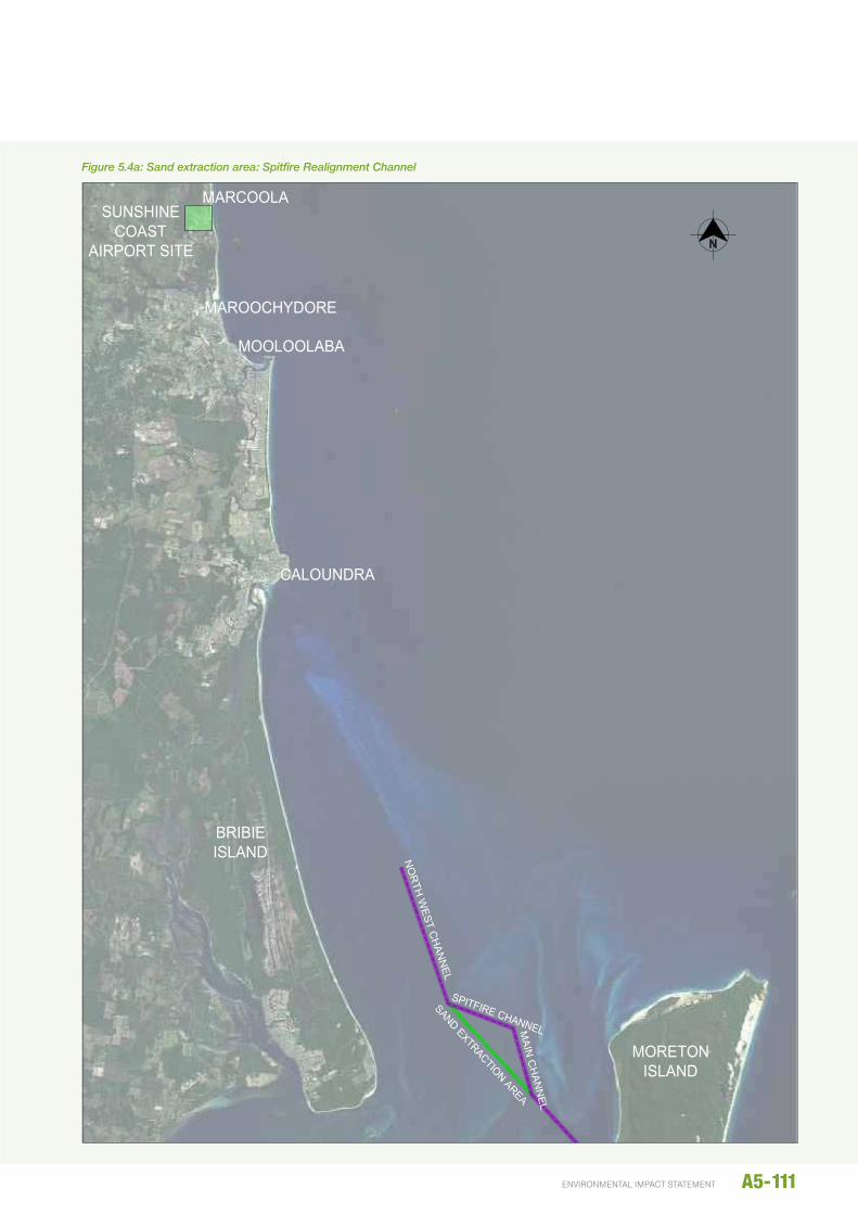
The triangular area enclosed by the existing Spitfire Channel and the Spitfire Realignment Channel is subject to a previously approved allocation for Riverside Sand Pty Ltd, as shown in Figure 5.4b.
SCA has been in consultation with PBPL to identify opportunities for a combined sand extraction area at the Spitfire Realignment Channel for the Project and PBPL’s current allocation. PBPL has indicated a preference for a shared dredging footprint that would be extended deeper than PBPL’s current approved dredging footprint, rather than wider. As dredging for the Project is likely to occur before PBPL undertakes any major dredging of the realignment, PBPL have indicated that it would be preferable for the SCA dredging to form a ‘shallow’ 300 m wide channel within the overall realignment channel footprint. This may then allow the realignment to be used for navigation by some vessels.
Based on bathymetry of the seabed surveyed in 2010, a 1.1 M m3 allocation would provide a 300 m wide channel to an average depth of approximately –11.55 m CD as shown in Figure 5.4b. The final level will depend on any prior dredging undertaken by PBPL and the quality of sand within the footprint.
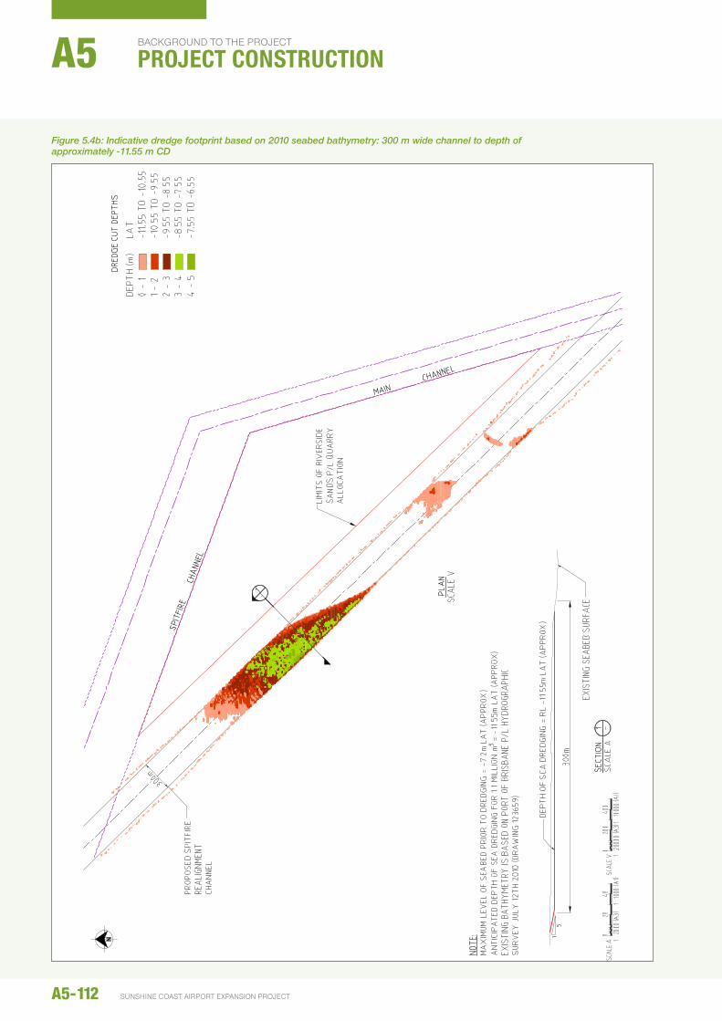
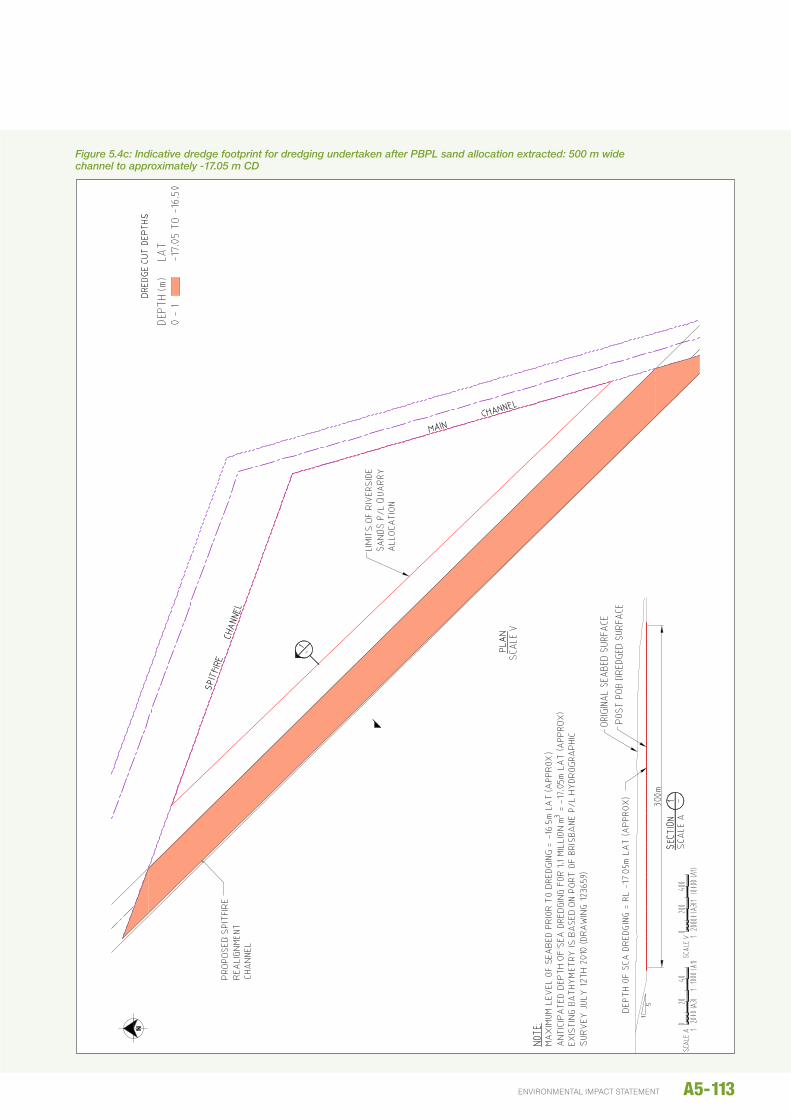
To develop a combined extraction area of 16.1 M m3 (i.e. PBPL’s 15 M m3 allocation and 1.1 M m3 for the Project) the base of the realignment would need to extend to approximately -17.05 m CD as shown in Figure 5.4c.
5.4.1.2 Dredging footprint bathymetry
A bathymetric survey of the Spitfire Realignment Channel seabed was supplied by PBPL for the project. The data received is based on a survey dated 12 july 2010 shown on PBPL plan 123659. The drawing indicates that it was a Maritime Safety Queensland (MSQ) standard ‘Class A’ survey with 100% coverage having a vertical tolerance (95%) +/-0.15 m and horizontal tolerance (95%) +/- 0.5 m. no anomalies were encountered when using the data for determining volumes.
Scour or siltation may have changed the seabed and quantities since the hydrographic survey was undertaken, however this is not expected to have had a substantial influence on seabed levels. The data is considered suitable for a dredging assessment for preparation of the environmental Impact Statement (eIS).
Further bathymetric survey of the dredge footprint will be undertaken before the commencement of dredging to measure and monitor dredging. Should PBPL undertake dredging before the Project, a further survey may be required to define the dredging footprint for the project. Typically, PBPL would carry out a survey after completing a dredging operation.
5.4.1.3 Geotechnical and geophysical information
Chapter C2 – Marine Geology describes the baseline geotechnical and geophysical conditions of the Spitfire Realignment Channel. It also describes the engineering qualities of the material in the Spitfire Realignment Channel based on existing geotechnical information.
Based on the interpretation of the information available at the time of the eIS, the Spitfire Realignment Channel was assessed as likely to yield sufficient quantity of sand (1.1 M m3) that will be suitable for the Project. The dredged material will comprise predominantly medium-grained sand.
A desktop assessment of the conditions at the Spitfire Realignment Channel, detailed in Chapter C2 – Marine Geology, indicates that there is a very low likelihood of sediment contamination within the dredge footprint.
5.4.1.4 Dredge vessel selection
The appropriate dredge vessel for the channel dredging will be a trailing suction hopper dredger (TShD). A TShD is a mobile type of dredger that removes seabed material as it travels using a trailing suction drag head connected by a suspended suction pipe to inboard pumps. Dredged material is stored in the on-board hopper compartment and is transported to the pump-out for reclamation by the TShD. Because of the large volume of material that can be stored in the on-board hoppers, and the relatively high travel speed of the vessel, this type of dredger is most
A5-110
background to the project
PROJECT CONSTRUCTIONA5
SunShIne coaSt aIrport eXpanSIon project
A5-111environmental impact statement
LAS
T M
OD
IFIE
D:1
/24/
2013
4:2
8 P
MC
AD
RE
F:P
:\PR
OJE
CTS
\602
7831
9\5.
CA
DD
\5.3
WO
RK
ING
\SK
ETC
HE
S\6
0278
319-
SK
100.
DW
G
SUNSHINE COAST AIRPORT EXPANSION PROJECT EISLOCALITY PLAN AND DRAWING LIST
60278319-SK100
REV A
MORETONISLAND
BRIBIEISLAND
CALOUNDRA
MOOLOOLABA
MAROOCHYDORE
MARCOOLASUNSHINE
COASTAIRPORT SITE
SUNSHINE COAST AIRPORTEXPANSION PROJECT EIS
MARINE ENGINEERING DRAWING PACKAGE
Figure 5.4a: Sand extraction area: Spitfire Realignment Channel
A5-112 SUNSHINE COAST AIRPORT EXPANSION PROJECT
bACkgROUNd TO THE PROJECT
PROJECT CONSTRUCTIONA5
Figure 5.4b: Indicative dredge footprint based on 2010 seabed bathymetry: 300 m wide channel to depth of approximately -11.55 m CD
A5-113environmental impact statement
Figure 5.4c: Indicative dredge footprint for dredging undertaken after PBPL sand allocation extracted: 500 m wide channel to approximately -17.05 m CD
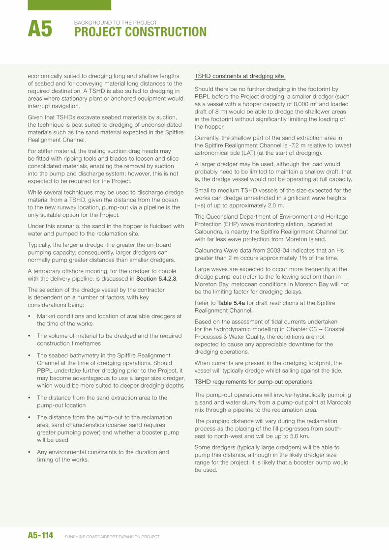
economically suited to dredging long and shallow lengths of seabed and for conveying material long distances to the required destination. A TShD is also suited to dredging in areas where stationary plant or anchored equipment would interrupt navigation.
Given that TShDs excavate seabed materials by suction, the technique is best suited to dredging of unconsolidated materials such as the sand material expected in the Spitfire Realignment Channel.
For stiffer material, the trailing suction drag heads may be fitted with ripping tools and blades to loosen and slice consolidated materials, enabling the removal by suction into the pump and discharge system; however, this is not expected to be required for the Project.
While several techniques may be used to discharge dredge material from a TShD, given the distance from the ocean to the new runway location, pump-out via a pipeline is the only suitable option for the Project.
under this scenario, the sand in the hopper is fluidised with water and pumped to the reclamation site.
Typically, the larger a dredge, the greater the on-board pumping capacity; consequently, larger dredgers can normally pump greater distances than smaller dredgers.
A temporary offshore mooring, for the dredger to couple with the delivery pipeline, is discussed in Section 5.4.2.3.
The selection of the dredge vessel by the contractor is dependent on a number of factors, with key considerations being:
y Market conditions and location of available dredgers at the time of the works
y The volume of material to be dredged and the required construction timeframes
y The seabed bathymetry in the Spitfire Realignment Channel at the time of dredging operations. Should PBPL undertake further dredging prior to the Project, it may become advantageous to use a larger size dredger, which would be more suited to deeper dredging depths
y The distance from the sand extraction area to the pump-out location
y The distance from the pump-out to the reclamation area, sand characteristics (coarser sand requires greater pumping power) and whether a booster pump will be used
y Any environmental constraints to the duration and timing of the works.
TSHD constraints at dredging site
Should there be no further dredging in the footprint by PBPL before the Project dredging, a smaller dredger (such as a vessel with a hopper capacity of 8,000 m3 and loaded draft of 8 m) would be able to dredge the shallower areas in the footprint without significantly limiting the loading of the hopper.
Currently, the shallow part of the sand extraction area in the Spitfire Realignment Channel is -7.2 m relative to lowest astronomical tide (LAT) (at the start of dredging).
A larger dredger may be used, although the load would probably need to be limited to maintain a shallow draft; that is, the dredge vessel would not be operating at full capacity.
Small to medium TShD vessels of the size expected for the works can dredge unrestricted in significant wave heights (hs) of up to approximately 2.0 m.
The Queensland Department of environment and heritage Protection (ehP) wave monitoring station, located at Caloundra, is nearby the Spitfire Realignment Channel but with far less wave protection from Moreton Island.
Caloundra Wave data from 2003-04 indicates that an hs greater than 2 m occurs approximately 1% of the time.
Large waves are expected to occur more frequently at the dredge pump-out (refer to the following section) than in Moreton Bay, metocean conditions in Moreton Bay will not be the limiting factor for dredging delays.
Refer to Table 5.4a for draft restrictions at the Spitfire Realignment Channel.
Based on the assessment of tidal currents undertaken for the hydrodynamic modelling in Chapter C3 – Coastal Processes & Water Quality, the conditions are not expected to cause any appreciable downtime for the dredging operations.
When currents are present in the dredging footprint, the vessel will typically dredge whilst sailing against the tide.
TSHD requirements for pump-out operations
The pump-out operations will involve hydraulically pumping a sand and water slurry from a pump-out point at Marcoola mix through a pipeline to the reclamation area.
The pumping distance will vary during the reclamation process as the placing of the fill progresses from south-east to north-west and will be up to 5.0 km.
Some dredgers (typically large dredgers) will be able to pump this distance, although in the likely dredger size range for the project, it is likely that a booster pump would be used.
A5-114
background to the project
PROJECT CONSTRUCTIONA5
SunShIne coaSt aIrport eXpanSIon project

The suitability of a range of TShDs that may be used for the project is shown in Table 5.4a. This assessment was based on a variety of TShD vessels operating around the world.
Modern TShD coupling-up systems to the flexible floating and steel submerged pipelines can normally take place in swell with a significant wave height of approximately 1.75–2.0 m. Wave data from ehP for the Mooloolaba Region from 2000–2004 indicate that, on average, the TShD would not be able to couple-up for approximately 5 to 7.5 per cent of the time. During winter, this could reduce to below 2.5 per cent, whereas, during summer the downtime could be in the order 10 per cent. Wave conditions vary from year to year and the downtime would vary accordingly.
During downtime, the dredge vessel would wait offshore until calmer conditions allow coupling up and pumping to proceed.
Further information on the wave climate can be found in Chapter C3 – Coastal Processes & Water Quality.
Preliminary assessment of TSHD
Table 5.4a summarises a preliminary assessment of TShD sizes for the dredging and reclamation works. Should dredging for the Project be undertaken with the existing bathymetry of the Spitfire Realignment Channel, it is likely that a medium size TShD would be most appropriate for the dredging.
however, should further deepening of the Spitfire Realignment Channel be undertaken prior to dredging for the Project, then the most cost efficient dredger is likely to be a larger vessel. The size of the TShD used for the works will also be influenced by the dredging volume, because of higher mobilisation and de-mobilisation costs associated with larger vessels.
A small dredger with a hopper capacity of 2,900m3, similar to The Brisbane, a locally-based TShD was included in the assessment for completeness. Small dredgers typically have lower pump-ashore power and would almost certainly require at least one booster pump. Consequently, it is unlikely that a TShD of this size would be used for the Project.
TShDs of the same size and class do not necessarily have consistent attributes because they are often designed to perform optimally for different dredging conditions.
Consequently, there are likely to be a number of vessels in each size category that are suitable for the Project (for example, smaller dredgers with high pumping capacity, or larger dredgers with a shallow draft). As a result, a wide size range of vessels could be used for the Project.
From the preliminary assessment undertaken for this eIS, the dredge vessel is expected to be in the range 8,000 m3 to 20,000 m3 hopper capacity, and the construction methodology presented herein is based on a vessel in that size range. Vessels in this size range would take up to 14 weeks to complete the dredging for the Project, assuming no major delays. These vessels have typical dimensions as outlined below:
y Length: 120–180 m
y Beam: 20–30 m
y Draft: 8–12.5 m.
As indicated in Table 5.4a smaller vessels (8,000 m3 to 12,500 m3) may need a land-based booster pump to enable sand to be pumped to the reclamation area, particularly the north-west area farthest from the pump out point.
Should a booster pump station be used, it would need to be located west of RWY 18/36 to avoid sensitive environmental areas and the RWY 18/36 obstacle limitation surface (OLS). It would also need to comply with all air and oil spill requirements.
The booster pump is likely to be a low-revving diesel engine, with a size of around 2,000 kW. noise attenuation will be provided for the booster pump as discussed in Chapter B15 – noise and Vibration.
The dredge vessel used for the works will need to comply with the environmental requirements of the Project, which are outlined in the Dredge Management Plan in Chapter e4.
5.4.1.5 Dredging operation
The general operating requirements for the dredger to meet the shipping procedures in the port and to achieve satisfactory environmental outcomes is described in Chapter e4 – Dredge Management Plan. essentially the dredging operation will involve:
1) hydraulically extracting sand mixed with water from the seabed in the Spitfire Realignment Channel using 1 or 2 trailing suction pipes and loading into the vessel’s hopper. The sand settles in the hopper and the supernatant water is returned to the bay until the hopper has reached its optimum fill level.
2) When the hopper of the dredge vessel is filled to the optimum level, it will travel along the designated shipping channels to the extent of the Port limits off Caloundra at Point Cartwright and then travel the most direct route to the pump-out site.
3) The TShD will be assisted by a tug at the pump-out site to position and couple to the floating pipeline.
A5-115environmental impact statement
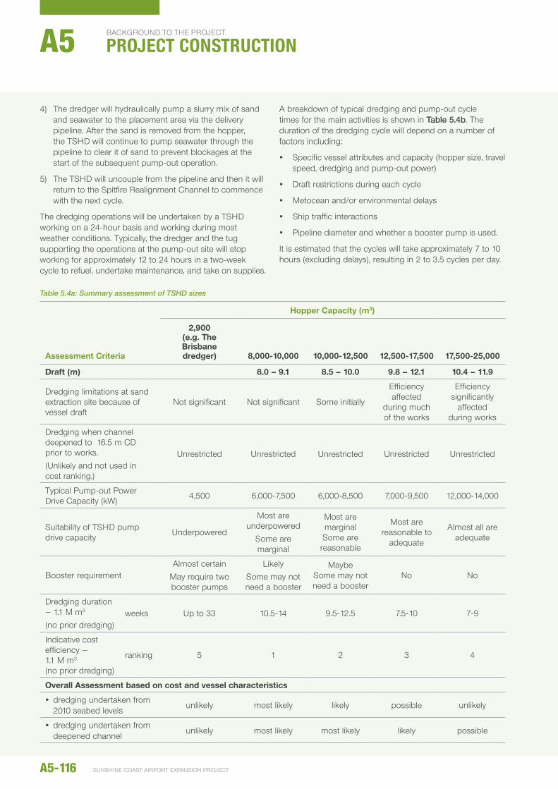
4) The dredger will hydraulically pump a slurry mix of sand and seawater to the placement area via the delivery pipeline. After the sand is removed from the hopper, the TShD will continue to pump seawater through the pipeline to clear it of sand to prevent blockages at the start of the subsequent pump-out operation.
5) The TShD will uncouple from the pipeline and then it will return to the Spitfire Realignment Channel to commence with the next cycle.
The dredging operations will be undertaken by a TShD working on a 24-hour basis and working during most weather conditions. Typically, the dredger and the tug supporting the operations at the pump-out site will stop working for approximately 12 to 24 hours in a two-week cycle to refuel, undertake maintenance, and take on supplies.
A breakdown of typical dredging and pump-out cycle times for the main activities is shown in Table 5.4b. The duration of the dredging cycle will depend on a number of factors including:
y Specific vessel attributes and capacity (hopper size, travel speed, dredging and pump-out power)
y Draft restrictions during each cycle
y Metocean and/or environmental delays
y Ship traffic interactions
y Pipeline diameter and whether a booster pump is used.
It is estimated that the cycles will take approximately 7 to 10 hours (excluding delays), resulting in 2 to 3.5 cycles per day.
Table 5.4a: Summary assessment of TSHD sizes
Assessment Criteria
hopper Capacity (m3)
2,900 (e.g. The Brisbane dredger) 8,000-10,000 10,000-12,500 12,500-17,500 17,500-25,000
draft (m) 8.0 – 9.1 8.5 – 10.0 9.8 – 12.1 10.4 – 11.9
Dredging limitations at sand extraction site because of vessel draft
not significant not significant Some initially
efficiency affected
during much of the works
efficiency significantly
affected during works
Dredging when channel deepened to 16.5 m CD prior to works.(unlikely and not used in cost ranking.)
unrestricted unrestricted unrestricted unrestricted unrestricted
Typical Pump-out Power Drive Capacity (kW) 4,500 6,000-7,500 6,000-8,500 7,000-9,500 12,000-14,000
Suitability of TShD pump drive capacity underpowered
Most are underpowered
Some are marginal
Most are marginalSome are reasonable
Most are reasonable to
adequate
Almost all are adequate
Booster requirementAlmost certain
May require two booster pumps
LikelySome may not need a booster
MaybeSome may not need a booster
no no
Dredging duration – 1.1 M m3 (no prior dredging)
weeks up to 33 10.5-14 9.5-12.5 7.5-10 7-9
Indicative cost efficiency – 1.1 M m3 (no prior dredging)
ranking 5 1 2 3 4
Overall Assessment based on cost and vessel characteristics
y dredging undertaken from 2010 seabed levels
unlikely most likely likely possible unlikely
y dredging undertaken from deepened channel
unlikely most likely most likely likely possible
A5-116
background to the project
PROJECT CONSTRUCTIONA5
SunShIne coaSt aIrport eXpanSIon project
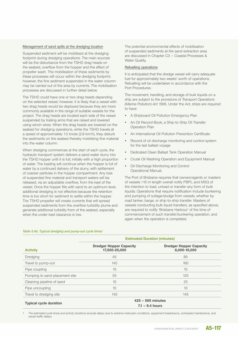
Management of sand spills at the dredging location
Suspended sediment will be mobilised at the dredging footprint during dredging operations. The main sources will be the disturbance from the TShD drag heads on the seabed, overflow from the hopper and the effect of propeller wash. The mobilisation of these sediments by these processes will occur within the dredging footprint; however, the fine sediment suspended in the water column may be carried out of the area by currents. The mobilisation processes are discussed in further detail below.
The TShD could have one or two drag heads depending on the selected vessel; however, it is likely that a vessel with two drag heads would be deployed because they are more commonly available in the range of suitable vessels for the project. The drag heads are located each side of the vessel suspended by trailing arms that are raised and lowered using winch wires. When the drag heads are lowered on the seabed for dredging operations, while the TShD travels at a speed of approximately 1.5 knots (2.8 km/h), they disturb the sediments on the seabed thereby mobilising fine material into the water column.
When dredging commences at the start of each cycle, the hydraulic transport system delivers a sand-water slurry into the TShD hopper until it is full, initially with a high proportion of water. The loading will continue when the hopper is full of water by a continued delivery of the slurry, with settlement of coarser particles in the hopper compartment. Any loss of suspended fine material and transport waters will be released, via an adjustable overflow, from the keel of the vessel. Once the hopper fills with sand to an optimum level, additional dredging is not effective because the retention time is too short for sediment to settle within the hopper. The TShD propeller will create currents that will spread suspended sediments from the overflow turbidity plume and generate additional turbidity from of the seabed, especially when the under keel clearance is low.
The potential environmental effects of mobilisation of suspended sediments at the sand extraction area are discussed in Chapter C3 – Coastal Processes & Water Quality.
Refuelling operations
It is anticipated that the dredge vessel will carry adequate fuel for approximately two weeks’ worth of operations. Refuelling will be undertaken in accordance with the Port Procedures.
The movement, handling, and storage of bulk liquids on a ship are subject to the provisions of Transport Operations (Marine Pollution) Act 1995. under the Act, ships are required to have:
y A Shipboard Oil Pollution emergency Plan
y An Oil Record Book, a Ship-to-Ship Oil Transfer Operation Plan
y An International Oil Pollution Prevention Certificate
y Record of oil discharge monitoring and control system for the last ballast voyage
y Dedicated Clean Ballast Tank Operation Manual
y Crude Oil Washing Operation and equipment Manual
y Oil Discharge Monitoring and Control Operational Manual.
The Port of Brisbane requires that owners/agents or masters of vessels >15 m length overall notify PBPL and MSQ of the intention to load, unload or transfer any form of bulk liquids. Operations that require notification include bunkering and pumping of sullage/sludge from vessels, whether by road tanker, barge, or ship-to-ship transfer. Masters of vessels conducting bulk liquid transfers, as specified above, are required to notify ‘Brisbane harbour’ of the time of commencement of such transfer/bunkering operation, and again when the operation is completed.
Table 5.4b: Typical dredging and pump-out cycle times1
Activity
Estimated duration (minutes)
dredger hopper Capacity 17,500-25,000
dredger hopper Capacity 8,000-10,000
Dredging 45 85
Travel to pump-out 145 160
Pipe coupling 15 15
Pumping to sand placement site 55 125
Cleaning pipeline of sand 15 25
Pipe uncoupling 10 10
Travel to dredging site 140 145
Typical cycle duration425 – 565 minutes
7.1 – 9.4 hours
1 The estimated cycle times and activity durations exclude delays due to extreme metocean conditions, equipment breakdowns, scheduled maintenance, and vessel traffic delays.
A5-117environmental impact statement
As the dredge vessel will be operating under existing procedures and at existing infrastructure, the proposed dredging works present no additional risk of fuel spills.
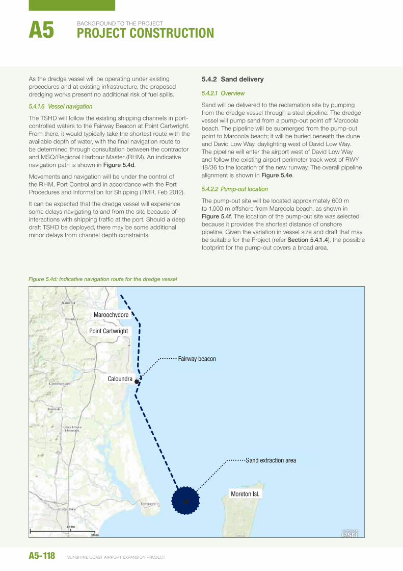
5.4.1.6 Vessel navigation
The TShD will follow the existing shipping channels in port-controlled waters to the Fairway Beacon at Point Cartwright. From there, it would typically take the shortest route with the available depth of water, with the final navigation route to be determined through consultation between the contractor and MSQ/Regional harbour Master (RhM). An indicative navigation path is shown in Figure 5.4d.
Movements and navigation will be under the control of the RhM, Port Control and in accordance with the Port Procedures and Information for Shipping (TMR, Feb 2012).
It can be expected that the dredge vessel will experience some delays navigating to and from the site because of interactions with shipping traffic at the port. Should a deep draft TShD be deployed, there may be some additional minor delays from channel depth constraints.
5.4.2 Sand delivery
5.4.2.1 Overview
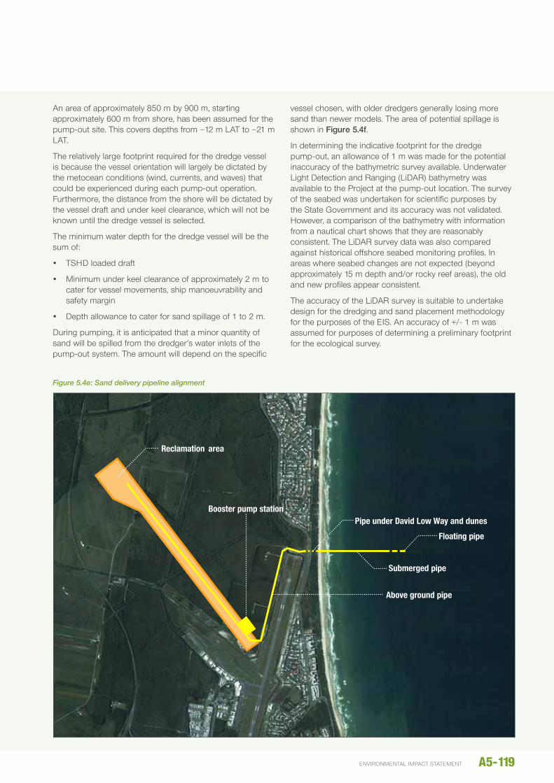
Sand will be delivered to the reclamation site by pumping from the dredge vessel through a steel pipeline. The dredge vessel will pump sand from a pump-out point off Marcoola beach. The pipeline will be submerged from the pump-out point to Marcoola beach; it will be buried beneath the dune and David Low Way, daylighting west of David Low Way. The pipeline will enter the airport west of David Low Way and follow the existing airport perimeter track west of RWY 18/36 to the location of the new runway. The overall pipeline alignment is shown in Figure 5.4e.
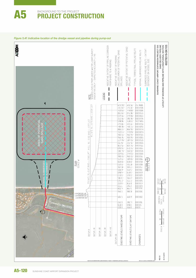
5.4.2.2 Pump-out location
The pump-out site will be located approximately 600 m to 1,000 m offshore from Marcoola beach, as shown in Figure 5.4f. The location of the pump-out site was selected because it provides the shortest distance of onshore pipeline. Given the variation in vessel size and draft that may be suitable for the Project (refer Section 5.4.1.4), the possible footprint for the pump-out covers a broad area.
Caloundra
Moreton Isl.
Maroochydore
Sand extraction area
Fairway beacon
Point Cartwright
Figure 5.4d: Indicative navigation route for the dredge vessel
A5-118
background to the project
PROJECT CONSTRUCTIONA5
SunShIne coaSt aIrport eXpanSIon project
An area of approximately 850 m by 900 m, starting approximately 600 m from shore, has been assumed for the pump-out site. This covers depths from −12 m LAT to −21 m LAT.
The relatively large footprint required for the dredge vessel is because the vessel orientation will largely be dictated by the metocean conditions (wind, currents, and waves) that could be experienced during each pump-out operation. Furthermore, the distance from the shore will be dictated by the vessel draft and under keel clearance, which will not be known until the dredge vessel is selected.
The minimum water depth for the dredge vessel will be the sum of:
y TShD loaded draft
y Minimum under keel clearance of approximately 2 m to cater for vessel movements, ship manoeuvrability and safety margin
y Depth allowance to cater for sand spillage of 1 to 2 m.
During pumping, it is anticipated that a minor quantity of sand will be spilled from the dredger’s water inlets of the pump-out system. The amount will depend on the specific
vessel chosen, with older dredgers generally losing more sand than newer models. The area of potential spillage is shown in Figure 5.4f.
In determining the indicative footprint for the dredge pump-out, an allowance of 1 m was made for the potential inaccuracy of the bathymetric survey available. underwater Light Detection and Ranging (LiDAR) bathymetry was available to the Project at the pump-out location. The survey of the seabed was undertaken for scientific purposes by the State Government and its accuracy was not validated. however, a comparison of the bathymetry with information from a nautical chart shows that they are reasonably consistent. The LiDAR survey data was also compared against historical offshore seabed monitoring profiles. In areas where seabed changes are not expected (beyond approximately 15 m depth and/or rocky reef areas), the old and new profiles appear consistent.
The accuracy of the LiDAR survey is suitable to undertake design for the dredging and sand placement methodology for the purposes of the eIS. An accuracy of +/- 1 m was assumed for purposes of determining a preliminary footprint for the ecological survey.
Reclamation area
Booster pump stationPipe under David Low Way and dunes
Floating pipe
Submerged pipe
Above ground pipe
Figure 5.4e: Sand delivery pipeline alignment
A5-119environmental impact statement
A5-120 SUNSHINE COAST AIRPORT EXPANSION PROJECT
BACkGROunD TO The PROjeCT
PROJECT CONSTRUCTIONA5
DAVID LOW WAY
EXISTING RUNWAY
NO
MIN
AL
SU
BM
ER
GE
DP
IPE
LIN
E A
LIG
NM
EN
T
LAST MODIFIED:9/11/2014 10:16 AMCAD REF:P:\PROJECTS\60248594\5. CADD\5.3 WORKING\SKETCHES\60248594-SK103.DWG
SU
NS
HIN
E C
OA
ST
AIR
PO
RT
EX
PA
NS
ION
PR
OJE
CT
EIS
SA
ND
DE
LIV
ER
Y P
IPE
LIN
E
6027
8319
-SK
103
RE
V B
03.1
0.20
13LA
YO
UT
OF
MO
OR
ING
AN
D P
IPE
LIN
E W
ITH
LO
NG
ITU
DIN
AL
SE
CTI
ON
Figure 5.4f: Indicative location of the dredge vessel and pipeline during pump-out
Before the contractor commences works, the pump-out site seabed will be surveyed to confirm navigation depth and to provide a baseline survey of the bathymetry for determining the removal of spilled sand, if required.
Management of sand spills at the pump-out location
A small amount of sand is expected to be spilled from the dredge vessel during pump-out operations. The primary source will be from the water inlets of the vessel’s pump-out system. The bottom hopper discharge doors could potentially add to the spillage. The capacity of the hopper discharge doors to hold water and sand will be subject to inspections at the start of and during works. The spillage will be localised close to where the TShD pumps out sand. Although the position and orientation of the vessel will vary according to the wind, wave and currents at the time, there will be prevailing conditions that tend to result in the vessel being positioned mainly in a few locations. Any sand spillage would be concentrated at these locations.
The amount of sand spilled during pump-out is relatively minor and depends on the individual dredge vessel, with older vessels typically spilling more sand.
The depth of sand at the pump-out location will be managed to ensure that adequate vessel under keel clearance is maintained. A specified level will be determined, at which point the sand will be re-dredged from the pump-out site and pumped to the reclamation. The level at which removal of spilt sand will occur will depend on the draft of the dredge vessel and the depth available at the site. The seabed would not be dredged below a certain tolerance level to minimise disturbance to the existing seabed. If the spilt sand does not reach the trigger level for removal, it would be left in place to disperse under normal coastal processes.
5.4.2.3 Temporary pump-out mooring and floating pipeline
A temporary mooring will be required to allow the TShD to couple to the floating pipeline and pump the sand-water slurry to the reclamation site. The details of a preferred arrangement for the pump-out will be determined closer to construction, and will largely depend on the equipment available for the works. Most systems allow the TShD to pump-out in any direction from a single point mooring. This type of mooring system has been tested over time and found to be satisfactory under most weather conditions.
A tug will be in attendance at the pump-out to:
y Position the TShD and assist to maintain the vessel direction
y Be on standby during the pump-out operations should problems be encountered
y Manoeuvre the floating pipeline.
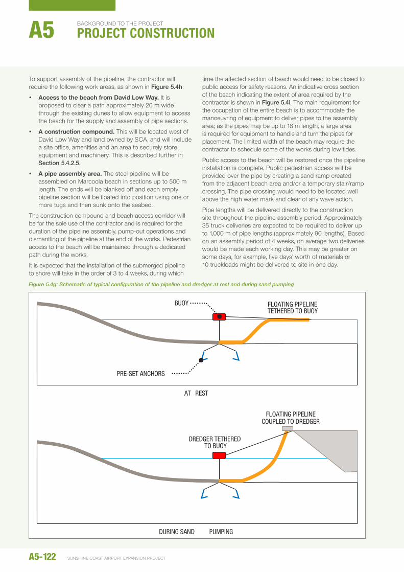
It is anticipated that a steel pipeline will be laid on the seabed to a distance of up to approximately 1 km from shore (described in Section 5.4.2.4), where it will be coupled to a length of flexible pipeline that transitions to fully floating pipeline over approximately 120 m (refer Figure 5.4g).
The flexible pipeline will comprise lengths of typically 10 m each bolted together. The size of the pipes may vary in diameter, but are generally slightly smaller than the nominal steel discharge pipeline diameter. For example, a TShD discharging through 1,000 mm diameter steel pipes will use a 900 mm diameter rubber floating pipe. The self-floating pipes have sufficient buoyancy to remain at the surface during pump-out operations when a high concentration of sand is hydraulically pumped and transported.
A buoy, with appropriate navigation lights, will be anchored where the steel pipeline connects to the flexible pipeline, and the floating pipeline will be tethered to this when the dredger is not pumping sand. The tug will also use the buoy as a mooring when the TShD is not conducting pump-out operations. The buoy will be anchored using pre-set anchors, which will be dragged into place.
When the TShD pumps sand, it will be tethered to the buoy using a suitably sized nylon mooring rope and its propellers and bow thrusters, controlled by a dynamic positioning system, will be used to hold position. The tug may also assist in holding the TShD’s heading. The orientation of the TShD will be dictated predominantly by the metocean conditions (wind, currents, and waves) during the operation. The tug will drag the floating pipeline to the dredger for it to be coupled to the dredger’s bow outlet.
Pennant buoys will mark the length and extremities of the submerged steel line, the anchor locations, and possibly the pump-out footprint as directed by the RhM. MSQ may decide to declare the actual pump-out footprint an exclusion zone for any other craft not associated with the project.
All temporary obstructions to navigation, fishing, and pleasure craft will be made known in notices to Mariners published by MSQ, advertising in local newspapers and other media, as well as notices at boat ramps and related recreational organisations.
5.4.2.4 Submerged pipeline to shore
The submerged pipeline that connects the self-floating discharge pipes from the TShD to the high water mark on the beach will comprise steel pipes of lengths 12 to 18 m, which will be fully welded together for strength and still retain a slight positive buoyancy to allow floating and sinking into position. It is anticipated that the pipes will have a diameter of 800 mm to 1,000 mm and a wall thickness of 20 to 24 mm.
The preferred construction method is to assemble the pipeline above and along the high tide mark on the beach for ease of installation, monitoring for leaks, and retrieving and removal at the end of the dredging works. Launching and retrieval will occur on high tides with the aid of bulldozers and small tugs.
A5-121environmental impact statement
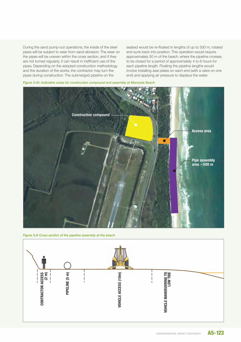
To support assembly of the pipeline, the contractor will require the following work areas, as shown in Figure 5.4h:
y Access to the beach from david Low Way. It is proposed to clear a path approximately 20 m wide through the existing dunes to allow equipment to access the beach for the supply and assembly of pipe sections.
y A construction compound. This will be located west of David Low Way and land owned by SCA, and will include a site office, amenities and an area to securely store equipment and machinery. This is described further in Section 5.4.2.5.
y A pipe assembly area. The steel pipeline will be assembled on Marcoola beach in sections up to 500 m length. The ends will be blanked off and each empty pipeline section will be floated into position using one or more tugs and then sunk onto the seabed.
The construction compound and beach access corridor will be for the sole use of the contractor and is required for the duration of the pipeline assembly, pump-out operations and dismantling of the pipeline at the end of the works. Pedestrian access to the beach will be maintained through a dedicated path during the works.
It is expected that the installation of the submerged pipeline to shore will take in the order of 3 to 4 weeks, during which
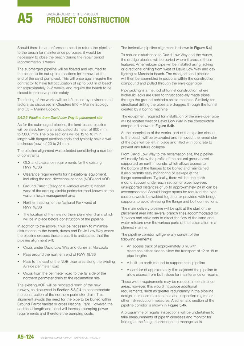
time the affected section of beach would need to be closed to public access for safety reasons. An indicative cross section of the beach indicating the extent of area required by the contractor is shown in Figure 5.4i. The main requirement for the occupation of the entire beach is to accommodate the manoeuvring of equipment to deliver pipes to the assembly area; as the pipes may be up to 18 m length, a large area is required for equipment to handle and turn the pipes for placement. The limited width of the beach may require the contractor to schedule some of the works during low tides.
Public access to the beach will be restored once the pipeline installation is complete. Public pedestrian access will be provided over the pipe by creating a sand ramp created from the adjacent beach area and/or a temporary stair/ramp crossing. The pipe crossing would need to be located well above the high water mark and clear of any wave action.
Pipe lengths will be delivered directly to the construction site throughout the pipeline assembly period. Approximately 35 truck deliveries are expected to be required to deliver up to 1,000 m of pipe lengths (approximately 90 lengths). Based on an assembly period of 4 weeks, on average two deliveries would be made each working day. This may be greater on some days, for example, five days’ worth of materials or 10 truckloads might be delivered to site in one day.
AT REST
PRE-SET ANCHORS
DURING SAND PUMPING
DREDGER TETHERED TO BUOY
FLOATING PIPELINE COUPLED TO DREDGER
FLOATING PIPELINE TETHERED TO BUOY
BUOY
Figure 5.4g: Schematic of typical configuration of the pipeline and dredger at rest and during sand pumping
A5-122
background to the project
PROJECT CONSTRUCTIONA5
SunShIne coaSt aIrport eXpanSIon project
During the sand pump-out operations, the inside of the steel pipes will be subject to wear from sand abrasion. The wear on the pipes will be uneven within the cross section, and if they are not turned regularly, it can result in inefficient use of the pipes. Depending on the adopted construction methodology and the duration of the works, the contractor may turn the pipes during construction. The submerged pipeline on the
seabed would be re-floated in lengths of up to 500 m, rotated and sunk back into position. This operation would require approximately 50 m of the beach, where the pipeline crosses, to be closed for a period of approximately 4 to 6 hours for each pipeline length. Floating the pipeline lengths would involve installing seal plates on each end (with a valve on one end) and applying air pressure to displace the water.
CONT
RACT
OR A
CCES
S (2
m)
PIPE
LINE
(5 m
)
VEHI
CLE
ACCE
SS (1
0m)
VEHI
CLE
MAN
OEUV
RING
TO
LOW
TID
E
Access area
Pipe assembly area ~500 m
Construction compound
Figure 5.4i Cross section of the pipeline assembly at the beach
Figure 5.4h: Indicative areas for construction compound and assembly at Marcoola Beach
A5-123environmental impact statement
Should there be an unforeseen need to return the pipeline to the beach for maintenance purposes, it would be necessary to close the beach during the repair period (approximately 1 week).
The submerged pipeline will be floated and returned to the beach to be cut up into sections for removal at the end of the sand pump-out. This will once again require the contractor to have full occupation of up to 500 m of beach for approximately 2–3 weeks, and require the beach to be closed to preserve public safety.
The timing of the works will be influenced by environmental factors, as discussed in Chapters B10 – Marine ecology and C5 – Marine ecology.
5.4.2.5 Pipeline from David Low Way to placement site
As for the submerged pipeline, the land-based pipeline will be steel, having an anticipated diameter of 800 mm to 1,000 mm. The pipe sections will be 12 to 18 m in length with flanged sections ends and typically have a wall thickness (new) of 20 to 24 mm.
The pipeline alignment was selected considering a number of constraints:
y OLS and clearance requirements for the existing RWY 18/36
y Clearance requirements for navigational equipment, including the non-directional beacon (nDB) and VOR
y Ground Parrot (Pezoporus wallicus wallicus) habitat west of the existing airside perimeter road known as the wallum heath management area
y northern section of the national Park west of RWY 18/36
y The location of the new northern perimeter drain, which will be in place before construction of the pipeline.
In addition to the above, it will be necessary to minimise disturbance to the beach, dunes and David Low Way where the pipeline crosses these areas. It is anticipated that the pipeline alignment will:
y Cross under David Low Way and dunes at Marcoola
y Pass around the northern end of RWY 18/36
y Pass to the east of the nDB clear area along the existing Airside perimeter road
y Cross from the perimeter road to the far side of the northern perimeter drain to the reclamation site.
The existing VOR will be relocated north of the new runway, as discussed in Section 5.3.2.4 to accommodate the construction of the northern perimeter drain. This alignment avoids the need for the pipe to be buried within Ground Parrot habitat or cross national Park. however, the additional length and bend will increase pumping power requirements and therefore the pumping costs.
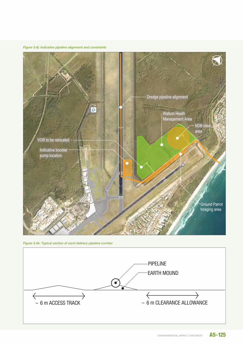
The indicative pipeline alignment is shown in Figure 5.4j.
To reduce disturbance to David Low Way and the dunes, the dredge pipeline will be buried where it crosses these features. An enveloper pipe will be installed using jacking or directional drilling from west of David Low Way and day lighting at Marcoola beach. The dredged sand pipeline will then be assembled in sections within the construction compound and pulled through the enveloper pipe.
Pipe jacking is a method of tunnel construction where hydraulic jacks are used to thrust specially made pipes through the ground behind a shield machine. Similarly, for directional drilling the pipes are dragged through the tunnel created by a boring machine.
The equipment required for installation of the enveloper pipe will be located west of David Low Way in the construction compound shown in Figure 5.4h.
At the completion of the works, part of the pipeline closest to the beach will be excavated and removed; the remainder of the pipe will be left in place and filled with concrete to prevent any future collapse.
From David Low Way to the reclamation site, the pipeline will mostly follow the profile of the natural ground level supported on earth mounds, which allows access to the bottom of the flanges to be bolted and maintained. It also permits easy monitoring of leakage at the flange connections. Typically, there will be one earth mound support under each section of pipe; however, unsupported distances of up to approximately 24 m can be accommodated. Should longer spans be required, the pipe sections would be welded together or provided with bridge supports to avoid stressing the flange and bolt connections.
The main delivery pipeline will be split at the start of the placement area into several branch lines accommodated by Y-pieces and valve sets to direct the flow of the sand and water mixture over the various parts of the reclamation in a planned manner.
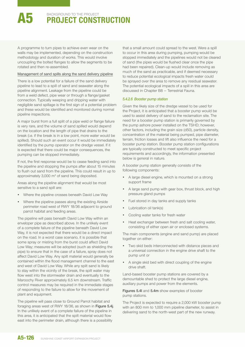
The pipeline corridor will generally consist of the following elements:
y An access track of approximately 6 m, with clearance either side to allow the transport of 12 or 18 m pipe lengths
y A built-up earth mound to support steel pipeline
y A corridor of approximately 6 m adjacent the pipeline to allow access from both sides for maintenance or repairs.
These width requirements may be reduced in constrained areas; however, this would introduce additional requirements, such as greater redundancy in the pipeline design, increased maintenance and inspection regime or other risk reduction measures. A schematic section of the pipeline corridor is shown in Figure 5.4k.
A programme of regular inspections will be undertaken to take measurements of pipe thicknesses and monitor for leaking at the flange connections to manage spills.
A5-124
background to the project
PROJECT CONSTRUCTIONA5
SunShIne coaSt aIrport eXpanSIon project
19 July 2014 \\aubne1fp003\projects\projects\60248594\6. draft docs\6.1 reports\rescope reports\002_construction methodology\images\construction images_20140711.docx 12 of 16
Figure 5.5j: Indicative pipeline alignment and constraints
Figure 5.5k: Typical section of sand delivery pipeline corridor
Dredge pipeline alignment
Indicative booster pump location
Wallum Heath Management Area
NDB clear area
VOR to be relocated
Ground Parrot foraging area
~ 6 m ACCESS TRACK ~ 6 m CLEARANCE ALLOWANCE
EARTH MOUND PIPELINE
Figure 5.4j: Indicative pipeline alignment and constraints
~ 6 m ACCESS TRACK ~ 6 m CLEARANCE ALLOWANCE
EARTH MOUND
PIPELINE
Figure 5.4k: Typical section of sand delivery pipeline corridor
A5-125environmental impact statement
A programme to turn pipes to achieve even wear on the walls may be implemented, depending on the construction methodology and duration of works. This would involve uncoupling the bolted flanges to allow the segments to be rotated and then re-assembled.
Management of sand spills along the sand delivery pipeline
There is a low potential for a failure of the sand delivery pipeline to lead to a spill of sand and seawater along the pipeline alignment. Leakage from the pipeline could be from a weld defect, pipe wear or through a flange/gasket connection. Typically weeping and dripping water with negligible sand spillage is the first sign of a potential problem and these would be identified and monitored during normal pipeline inspections.
A major burst from a full split of a pipe weld or flange failure is very rare, and the volume of sand spilled would depend on the location and the length of pipe that drains to the break (i.e. if the break is in a low point, more water would be spilled). Should such an event occur it would be immediately identified by the pump operator on the dredge vessel. If it is expected that there could be major consequences, the pumping can be stopped immediately.
If not, the first response would be to cease feeding sand into the pipeline and stopping the pumps after about 15 minutes to flush out sand from the pipeline. This could result in up to approximately 3,000 m3 of sand being deposited.
Areas along the pipeline alignment that would be most sensitive to a sand spill are:
y Where the pipeline crosses beneath David Low Way
y Where the pipeline passes along the existing Airside perimeter road west of RWY 18/36 adjacent to ground parrot habitat and feeding areas.
The pipeline will pass beneath David Low Way within an enveloper pipe as described above. In the unlikely event of a complete failure of the pipeline beneath David Low Way, it is not expected that there would be a direct impact on the road. In a worst case scenario, it is possible that some spray or misting from the burst could affect David Low Way; measures will be adopted (such as shielding the pipe) to ensure that in the case of a failure, spray does not affect David Low Way. Any spilt material would generally be contained within the flood management channel to the east and west of David Low Way. While any spilt sand is likely to stay within the vicinity of the break, the spilt water may flow west into the stormwater drain and eventually to the Maroochy River approximately 6.5 km downstream. Traffic control measures may be required in the immediate stages of responding to the failure to allow for the movement of plant and equipment.
The pipeline will pass close to Ground Parrot habitat and foraging areas west of RWY 18/36, as shown in Figure 5.4j. In the unlikely event of a complete failure of the pipeline in this area, it is anticipated that the spilt material would flow east into the perimeter drain, although there is a possibility
that a small amount could spread to the west. Were a spill to occur in this area during pumping, pumping would be stopped immediately and the pipelines would not be cleared of sand (the pipes would be flushed clear once the pipe had been repaired). Clean-up would include removing as much of the sand as practicable, and if deemed necessary to reduce potential ecological impacts fresh water could be sprayed over the area to remove any residual seawater. The potential ecological impacts of a spill in this area are discussed in Chapter B8 – Terrestrial Fauna.
5.4.2.6 Booster pump station
Given the likely size of the dredge vessel to be used for the Project, it is anticipated that a booster pump would be used to assist delivery of sand to the reclamation site. The need for a booster pump station is primarily governed by the pump ashore power installed on the TShD; however, other factors, including the grain size (d50), particle density, concentration of the material being pumped, pipe diameter, terrain, friction losses and lift also influence the need for a booster pump station. Booster pump station configurations are typically constructed to meet specific project requirements and accordingly, the information presented below is general in nature.
A booster pump station generally consists of the following components:
y A large diesel engine, which is mounted on a strong support frame
y A large sand pump with gear box, thrust block, and high pressure gland pumps
y Fuel stored in day tanks and supply tanks
y Lubrication oil tank(s)
y Cooling water tanks for fresh water
y heat exchanger between fresh and salt cooling water, consisting of either open air or enclosed systems.
The main components (engine and sand pump) are placed together on either:
y Two skid beds interconnected with distance pieces and a universal connection in the engine drive shaft to the pump unit or
y A single skid bed with direct coupling of the engine drive shaft.
Land-based booster pump stations are covered by a demountable shed to protect the large diesel engine, auxiliary pumps and power from the elements.
Figures 5.4l and 5.4m show examples of booster pump stations.
The Project is expected to require a 2,000 kW booster pump with an 800 mm to 1,000 mm pipeline diameter, to assist in delivering sand to the north-west part of the new runway.
A5-126
background to the project
PROJECT CONSTRUCTIONA5
SunShIne coaSt aIrport eXpanSIon project
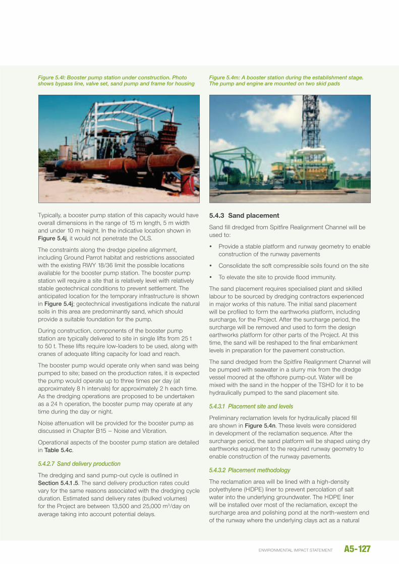
Typically, a booster pump station of this capacity would have overall dimensions in the range of 15 m length, 5 m width and under 10 m height. In the indicative location shown in Figure 5.4j, it would not penetrate the OLS.
The constraints along the dredge pipeline alignment, including Ground Parrot habitat and restrictions associated with the existing RWY 18/36 limit the possible locations available for the booster pump station. The booster pump station will require a site that is relatively level with relatively stable geotechnical conditions to prevent settlement. The anticipated location for the temporary infrastructure is shown in Figure 5.4j; geotechnical investigations indicate the natural soils in this area are predominantly sand, which should provide a suitable foundation for the pump.
During construction, components of the booster pump station are typically delivered to site in single lifts from 25 t to 50 t. These lifts require low-loaders to be used, along with cranes of adequate lifting capacity for load and reach.
The booster pump would operate only when sand was being pumped to site; based on the production rates, it is expected the pump would operate up to three times per day (at approximately 8 h intervals) for approximately 2 h each time. As the dredging operations are proposed to be undertaken as a 24 h operation, the booster pump may operate at any time during the day or night.
noise attenuation will be provided for the booster pump as discussed in Chapter B15 – noise and Vibration.
Operational aspects of the booster pump station are detailed in Table 5.4c.
5.4.2.7 Sand delivery production
The dredging and sand pump-out cycle is outlined in Section 5.4.1.5. The sand delivery production rates could vary for the same reasons associated with the dredging cycle duration. estimated sand delivery rates (bulked volumes) for the Project are between 13,500 and 25,000 m3/day on average taking into account potential delays.
5.4.3 Sand placement
Sand fill dredged from Spitfire Realignment Channel will be used to:
y Provide a stable platform and runway geometry to enable construction of the runway pavements
y Consolidate the soft compressible soils found on the site
y To elevate the site to provide flood immunity.
The sand placement requires specialised plant and skilled labour to be sourced by dredging contractors experienced in major works of this nature. The initial sand placement will be profiled to form the earthworks platform, including surcharge, for the Project. After the surcharge period, the surcharge will be removed and used to form the design earthworks platform for other parts of the Project. At this time, the sand will be reshaped to the final embankment levels in preparation for the pavement construction.
The sand dredged from the Spitfire Realignment Channel will be pumped with seawater in a slurry mix from the dredge vessel moored at the offshore pump-out. Water will be mixed with the sand in the hopper of the TShD for it to be hydraulically pumped to the sand placement site.
5.4.3.1 Placement site and levels
Preliminary reclamation levels for hydraulically placed fill are shown in Figure 5.4n. These levels were considered in development of the reclamation sequence. After the surcharge period, the sand platform will be shaped using dry earthworks equipment to the required runway geometry to enable construction of the runway pavements.
5.4.3.2 Placement methodology
The reclamation area will be lined with a high-density polyethylene (hDPe) liner to prevent percolation of salt water into the underlying groundwater. The hDPe liner will be installed over most of the reclamation, except the surcharge area and polishing pond at the north-western end of the runway where the underlying clays act as a natural
Figure 5.4l: Booster pump station under construction. Photo shows bypass line, valve set, sand pump and frame for housing
Figure 5.4m: A booster station during the establishment stage. The pump and engine are mounted on two skid pads
A5-127environmental impact statement
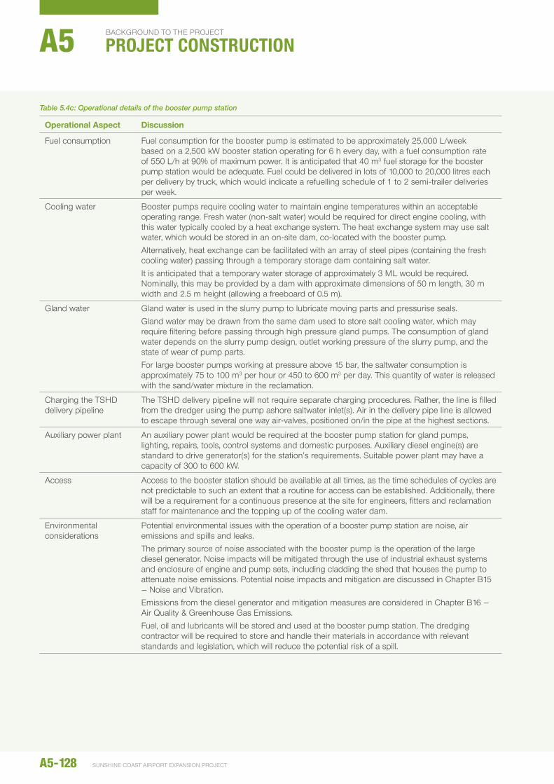
Table 5.4c: Operational details of the booster pump station
Operational Aspect discussion
Fuel consumption Fuel consumption for the booster pump is estimated to be approximately 25,000 L/week based on a 2,500 kW booster station operating for 6 h every day, with a fuel consumption rate of 550 L/h at 90% of maximum power. It is anticipated that 40 m3 fuel storage for the booster pump station would be adequate. Fuel could be delivered in lots of 10,000 to 20,000 litres each per delivery by truck, which would indicate a refuelling schedule of 1 to 2 semi-trailer deliveries per week.
Cooling water Booster pumps require cooling water to maintain engine temperatures within an acceptable operating range. Fresh water (non-salt water) would be required for direct engine cooling, with this water typically cooled by a heat exchange system. The heat exchange system may use salt water, which would be stored in an on-site dam, co-located with the booster pump.Alternatively, heat exchange can be facilitated with an array of steel pipes (containing the fresh cooling water) passing through a temporary storage dam containing salt water.It is anticipated that a temporary water storage of approximately 3 ML would be required. nominally, this may be provided by a dam with approximate dimensions of 50 m length, 30 m width and 2.5 m height (allowing a freeboard of 0.5 m).
Gland water Gland water is used in the slurry pump to lubricate moving parts and pressurise seals.Gland water may be drawn from the same dam used to store salt cooling water, which may require filtering before passing through high pressure gland pumps. The consumption of gland water depends on the slurry pump design, outlet working pressure of the slurry pump, and the state of wear of pump parts.For large booster pumps working at pressure above 15 bar, the saltwater consumption is approximately 75 to 100 m3 per hour or 450 to 600 m3 per day. This quantity of water is released with the sand/water mixture in the reclamation.
Charging the TShD delivery pipeline
The TShD delivery pipeline will not require separate charging procedures. Rather, the line is filled from the dredger using the pump ashore saltwater inlet(s). Air in the delivery pipe line is allowed to escape through several one way air-valves, positioned on/in the pipe at the highest sections.
Auxiliary power plant An auxiliary power plant would be required at the booster pump station for gland pumps, lighting, repairs, tools, control systems and domestic purposes. Auxiliary diesel engine(s) are standard to drive generator(s) for the station’s requirements. Suitable power plant may have a capacity of 300 to 600 kW.
Access Access to the booster station should be available at all times, as the time schedules of cycles are not predictable to such an extent that a routine for access can be established. Additionally, there will be a requirement for a continuous presence at the site for engineers, fitters and reclamation staff for maintenance and the topping up of the cooling water dam.
environmental considerations
Potential environmental issues with the operation of a booster pump station are noise, air emissions and spills and leaks. The primary source of noise associated with the booster pump is the operation of the large diesel generator. noise impacts will be mitigated through the use of industrial exhaust systems and enclosure of engine and pump sets, including cladding the shed that houses the pump to attenuate noise emissions. Potential noise impacts and mitigation are discussed in Chapter B15 – noise and Vibration.emissions from the diesel generator and mitigation measures are considered in Chapter B16 –Air Quality & Greenhouse Gas emissions.Fuel, oil and lubricants will be stored and used at the booster pump station. The dredging contractor will be required to store and handle their materials in accordance with relevant standards and legislation, which will reduce the potential risk of a spill.
A5-128
background to the project
PROJECT CONSTRUCTIONA5
SunShIne coaSt aIrport eXpanSIon project

A5-129environmental impact statement19 July 2014 \\aubne1fp003\projects\projects\60248594\6. draft docs\6.1 reports\rescope reports\002_construction methodology\images\construction images_20140711.docx 13 of 16
Figure 5.5n: Preliminary reclamation levels
Surcharge area, ~RL 5.65 m AHD
Fill platform, ~RL 4.65 m AHD
Figure 5.4n: Preliminary reclamation levels
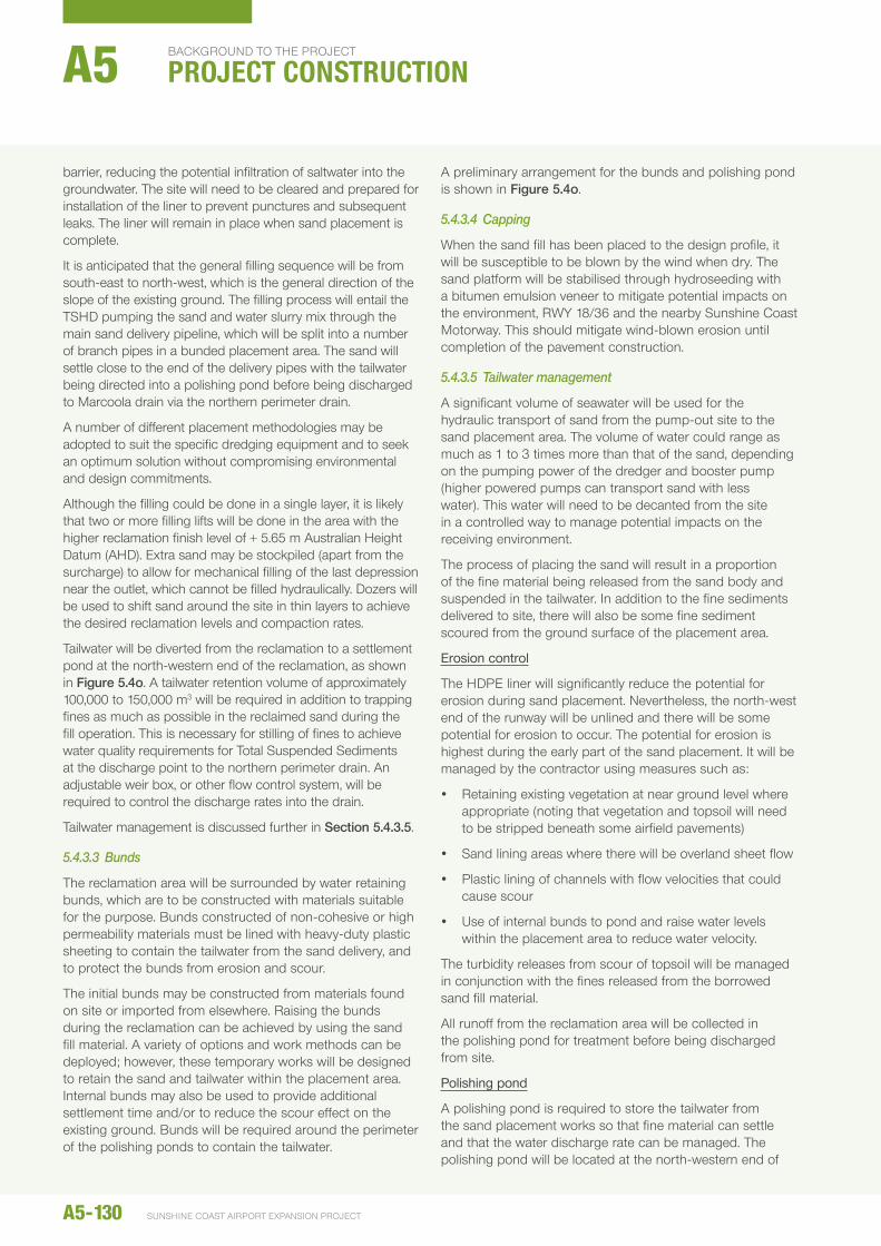
barrier, reducing the potential infiltration of saltwater into the groundwater. The site will need to be cleared and prepared for installation of the liner to prevent punctures and subsequent leaks. The liner will remain in place when sand placement is complete.
It is anticipated that the general filling sequence will be from south-east to north-west, which is the general direction of the slope of the existing ground. The filling process will entail the TShD pumping the sand and water slurry mix through the main sand delivery pipeline, which will be split into a number of branch pipes in a bunded placement area. The sand will settle close to the end of the delivery pipes with the tailwater being directed into a polishing pond before being discharged to Marcoola drain via the northern perimeter drain.
A number of different placement methodologies may be adopted to suit the specific dredging equipment and to seek an optimum solution without compromising environmental and design commitments.
Although the filling could be done in a single layer, it is likely that two or more filling lifts will be done in the area with the higher reclamation finish level of + 5.65 m Australian height Datum (AhD). extra sand may be stockpiled (apart from the surcharge) to allow for mechanical filling of the last depression near the outlet, which cannot be filled hydraulically. Dozers will be used to shift sand around the site in thin layers to achieve the desired reclamation levels and compaction rates.
Tailwater will be diverted from the reclamation to a settlement pond at the north-western end of the reclamation, as shown in Figure 5.4o. A tailwater retention volume of approximately 100,000 to 150,000 m3 will be required in addition to trapping fines as much as possible in the reclaimed sand during the fill operation. This is necessary for stilling of fines to achieve water quality requirements for Total Suspended Sediments at the discharge point to the northern perimeter drain. An adjustable weir box, or other flow control system, will be required to control the discharge rates into the drain.
Tailwater management is discussed further in Section 5.4.3.5.
5.4.3.3 Bunds
The reclamation area will be surrounded by water retaining bunds, which are to be constructed with materials suitable for the purpose. Bunds constructed of non-cohesive or high permeability materials must be lined with heavy-duty plastic sheeting to contain the tailwater from the sand delivery, and to protect the bunds from erosion and scour.
The initial bunds may be constructed from materials found on site or imported from elsewhere. Raising the bunds during the reclamation can be achieved by using the sand fill material. A variety of options and work methods can be deployed; however, these temporary works will be designed to retain the sand and tailwater within the placement area. Internal bunds may also be used to provide additional settlement time and/or to reduce the scour effect on the existing ground. Bunds will be required around the perimeter of the polishing ponds to contain the tailwater.
A preliminary arrangement for the bunds and polishing pond is shown in Figure 5.4o.
5.4.3.4 Capping
When the sand fill has been placed to the design profile, it will be susceptible to be blown by the wind when dry. The sand platform will be stabilised through hydroseeding with a bitumen emulsion veneer to mitigate potential impacts on the environment, RWY 18/36 and the nearby Sunshine Coast Motorway. This should mitigate wind-blown erosion until completion of the pavement construction.
5.4.3.5 Tailwater management
A significant volume of seawater will be used for the hydraulic transport of sand from the pump-out site to the sand placement area. The volume of water could range as much as 1 to 3 times more than that of the sand, depending on the pumping power of the dredger and booster pump (higher powered pumps can transport sand with less water). This water will need to be decanted from the site in a controlled way to manage potential impacts on the receiving environment.
The process of placing the sand will result in a proportion of the fine material being released from the sand body and suspended in the tailwater. In addition to the fine sediments delivered to site, there will also be some fine sediment scoured from the ground surface of the placement area.
Erosion control
The hDPe liner will significantly reduce the potential for erosion during sand placement. nevertheless, the north-west end of the runway will be unlined and there will be some potential for erosion to occur. The potential for erosion is highest during the early part of the sand placement. It will be managed by the contractor using measures such as:
y Retaining existing vegetation at near ground level where appropriate (noting that vegetation and topsoil will need to be stripped beneath some airfield pavements)
y Sand lining areas where there will be overland sheet flow
y Plastic lining of channels with flow velocities that could cause scour
y use of internal bunds to pond and raise water levels within the placement area to reduce water velocity.
The turbidity releases from scour of topsoil will be managed in conjunction with the fines released from the borrowed sand fill material.
All runoff from the reclamation area will be collected in the polishing pond for treatment before being discharged from site.
Polishing pond
A polishing pond is required to store the tailwater from the sand placement works so that fine material can settle and that the water discharge rate can be managed. The polishing pond will be located at the north-western end of
A5-130
background to the project
PROJECT CONSTRUCTIONA5
SunShIne coaSt aIrport eXpanSIon project
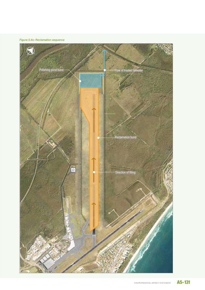
A5-131environmental impact statement19 July 2014 \\aubne1fp003\projects\projects\60248594\6. draft docs\6.1 reports\rescope reports\002_construction methodology\images\construction images_20140711.docx 14 of 16
Figure 5.5o: Reclamation sequence
Reclamation bund
Flow of treated tailwater
Direction of filling
Polishing pond bund
Figure 5.4o: Reclamation sequence
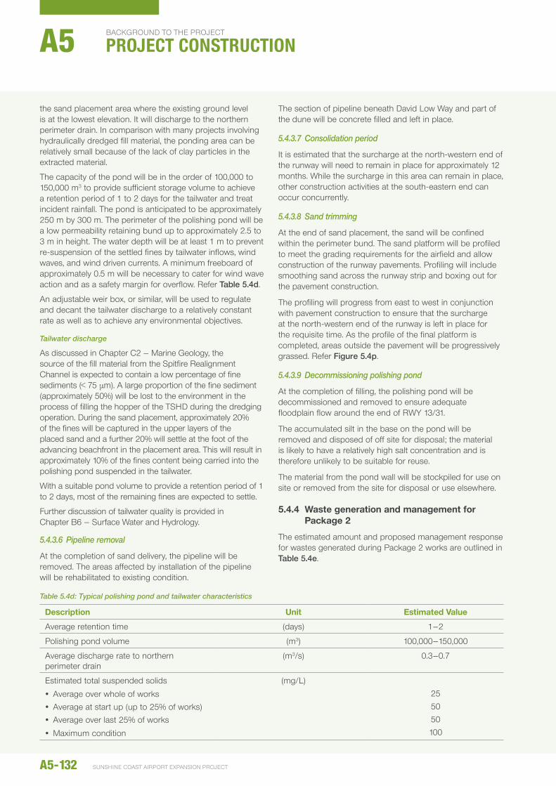
the sand placement area where the existing ground level is at the lowest elevation. It will discharge to the northern perimeter drain. In comparison with many projects involving hydraulically dredged fill material, the ponding area can be relatively small because of the lack of clay particles in the extracted material.
The capacity of the pond will be in the order of 100,000 to 150,000 m3 to provide sufficient storage volume to achieve a retention period of 1 to 2 days for the tailwater and treat incident rainfall. The pond is anticipated to be approximately 250 m by 300 m. The perimeter of the polishing pond will be a low permeability retaining bund up to approximately 2.5 to 3 m in height. The water depth will be at least 1 m to prevent re-suspension of the settled fines by tailwater inflows, wind waves, and wind driven currents. A minimum freeboard of approximately 0.5 m will be necessary to cater for wind wave action and as a safety margin for overflow. Refer Table 5.4d.
An adjustable weir box, or similar, will be used to regulate and decant the tailwater discharge to a relatively constant rate as well as to achieve any environmental objectives.
Tailwater discharge
As discussed in Chapter C2 – Marine Geology, the source of the fill material from the Spitfire Realignment Channel is expected to contain a low percentage of fine sediments (< 75 µm). A large proportion of the fine sediment (approximately 50%) will be lost to the environment in the process of filling the hopper of the TShD during the dredging operation. During the sand placement, approximately 20% of the fines will be captured in the upper layers of the placed sand and a further 20% will settle at the foot of the advancing beachfront in the placement area. This will result in approximately 10% of the fines content being carried into the polishing pond suspended in the tailwater.
With a suitable pond volume to provide a retention period of 1 to 2 days, most of the remaining fines are expected to settle.
Further discussion of tailwater quality is provided in Chapter B6 – Surface Water and hydrology.
5.4.3.6 Pipeline removal
At the completion of sand delivery, the pipeline will be removed. The areas affected by installation of the pipeline will be rehabilitated to existing condition.
The section of pipeline beneath David Low Way and part of the dune will be concrete filled and left in place.
5.4.3.7 Consolidation period
It is estimated that the surcharge at the north-western end of the runway will need to remain in place for approximately 12 months. While the surcharge in this area can remain in place, other construction activities at the south-eastern end can occur concurrently.
5.4.3.8 Sand trimming
At the end of sand placement, the sand will be confined within the perimeter bund. The sand platform will be profiled to meet the grading requirements for the airfield and allow construction of the runway pavements. Profiling will include smoothing sand across the runway strip and boxing out for the pavement construction.
The profiling will progress from east to west in conjunction with pavement construction to ensure that the surcharge at the north-western end of the runway is left in place for the requisite time. As the profile of the final platform is completed, areas outside the pavement will be progressively grassed. Refer Figure 5.4p.
5.4.3.9 Decommissioning polishing pond
At the completion of filling, the polishing pond will be decommissioned and removed to ensure adequate floodplain flow around the end of RWY 13/31.
The accumulated silt in the base on the pond will be removed and disposed of off site for disposal; the material is likely to have a relatively high salt concentration and is therefore unlikely to be suitable for reuse.
The material from the pond wall will be stockpiled for use on site or removed from the site for disposal or use elsewhere.
5.4.4 Waste generation and management for Package 2
The estimated amount and proposed management response for wastes generated during Package 2 works are outlined in Table 5.4e.
Table 5.4d: Typical polishing pond and tailwater characteristics
description Unit Estimated value
Average retention time (days) 1–2
Polishing pond volume (m3) 100,000–150,000
Average discharge rate to northern perimeter drain
(m3/s) 0.3–0.7
estimated total suspended solids
y Average over whole of works y Average at start up (up to 25% of works) y Average over last 25% of works
y Maximum condition
(mg/L)255050100
A5-132
background to the project
PROJECT CONSTRUCTIONA5
SunShIne coaSt aIrport eXpanSIon project

A5-133environmental impact statement
19 J
uly
2014
\\a
ubne
1fp0
03\p
roje
cts\
proj
ects
\602
4859
4\6.
dra
ft do
cs\6
.1 re
ports
\resc
ope
repo
rts\0
02_c
onst
ruct
ion
met
hodo
logy
\imag
es\c
onst
ruct
ion
imag
es_2
0140
711.
docx
15
of 1
6
Figu
re 5
.5p:
San
d re
hand
ling
Exist
ing ai
rside
pe
rimete
r fen
ce
Sand
area
at en
d of s
and p
lacem
ent
Sand
area
at en
d of s
and r
ehan
dling
Temp
orar
y airs
ide fe
nce
Cons
tructi
on co
mpou
nd
Figure 5.4p: Sand rehandling
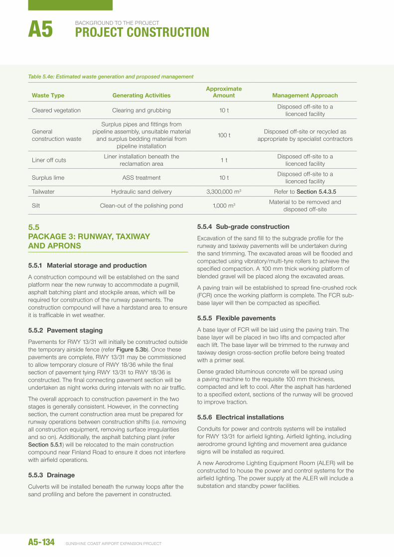
5.5 PACkAGE 3: RUNWAy, TAXIWAy ANd APRONS
5.5.1 Material storage and production
A construction compound will be established on the sand platform near the new runway to accommodate a pugmill, asphalt batching plant and stockpile areas, which will be required for construction of the runway pavements. The construction compound will have a hardstand area to ensure it is trafficable in wet weather.
5.5.2 Pavement staging
Pavements for RWY 13/31 will initially be constructed outside the temporary airside fence (refer Figure 5.3b). Once these pavements are complete, RWY 13/31 may be commissioned to allow temporary closure of RWY 18/36 while the final section of pavement tying RWY 13/31 to RWY 18/36 is constructed. The final connecting pavement section will be undertaken as night works during intervals with no air traffic.
The overall approach to construction pavement in the two stages is generally consistent. however, in the connecting section, the current construction area must be prepared for runway operations between construction shifts (i.e. removing all construction equipment, removing surface irregularities and so on). Additionally, the asphalt batching plant (refer Section 5.5.1) will be relocated to the main construction compound near Finland Road to ensure it does not interfere with airfield operations.
5.5.3 drainage
Culverts will be installed beneath the runway loops after the sand profiling and before the pavement in constructed.
5.5.4 Sub-grade construction
excavation of the sand fill to the subgrade profile for the runway and taxiway pavements will be undertaken during the sand trimming. The excavated areas will be flooded and compacted using vibratory/multi-tyre rollers to achieve the specified compaction. A 100 mm thick working platform of blended gravel will be placed along the excavated areas.
A paving train will be established to spread fine-crushed rock (FCR) once the working platform is complete. The FCR sub-base layer will then be compacted as specified.
5.5.5 Flexible pavements
A base layer of FCR will be laid using the paving train. The base layer will be placed in two lifts and compacted after each lift. The base layer will be trimmed to the runway and taxiway design cross-section profile before being treated with a primer seal.
Dense graded bituminous concrete will be spread using a paving machine to the requisite 100 mm thickness, compacted and left to cool. After the asphalt has hardened to a specified extent, sections of the runway will be grooved to improve traction.
5.5.6 Electrical installations
Conduits for power and controls systems will be installed for RWY 13/31 for airfield lighting. Airfield lighting, including aerodrome ground lighting and movement area guidance signs will be installed as required.
A new Aerodrome Lighting equipment Room (ALeR) will be constructed to house the power and control systems for the airfield lighting. The power supply at the ALeR will include a substation and standby power facilities.
Table 5.4e: Estimated waste generation and proposed management
Waste Type Generating ActivitiesApproximate
Amount Management Approach
Cleared vegetation Clearing and grubbing 10 t Disposed off-site to a licenced facility
General construction waste
Surplus pipes and fittings from pipeline assembly, unsuitable material
and surplus bedding material from pipeline installation
100 t Disposed off-site or recycled as appropriate by specialist contractors
Liner off cuts Liner installation beneath the reclamation area 1 t Disposed off-site to a
licenced facility
Surplus lime ASS treatment 10 t Disposed off-site to a licenced facility
Tailwater hydraulic sand delivery 3,300,000 m3 Refer to Section 5.4.3.5
Silt Clean-out of the polishing pond 1,000 m3 Material to be removed and disposed off-site
A5-134
background to the project
PROJECT CONSTRUCTIONA5
SunShIne coaSt aIrport eXpanSIon project
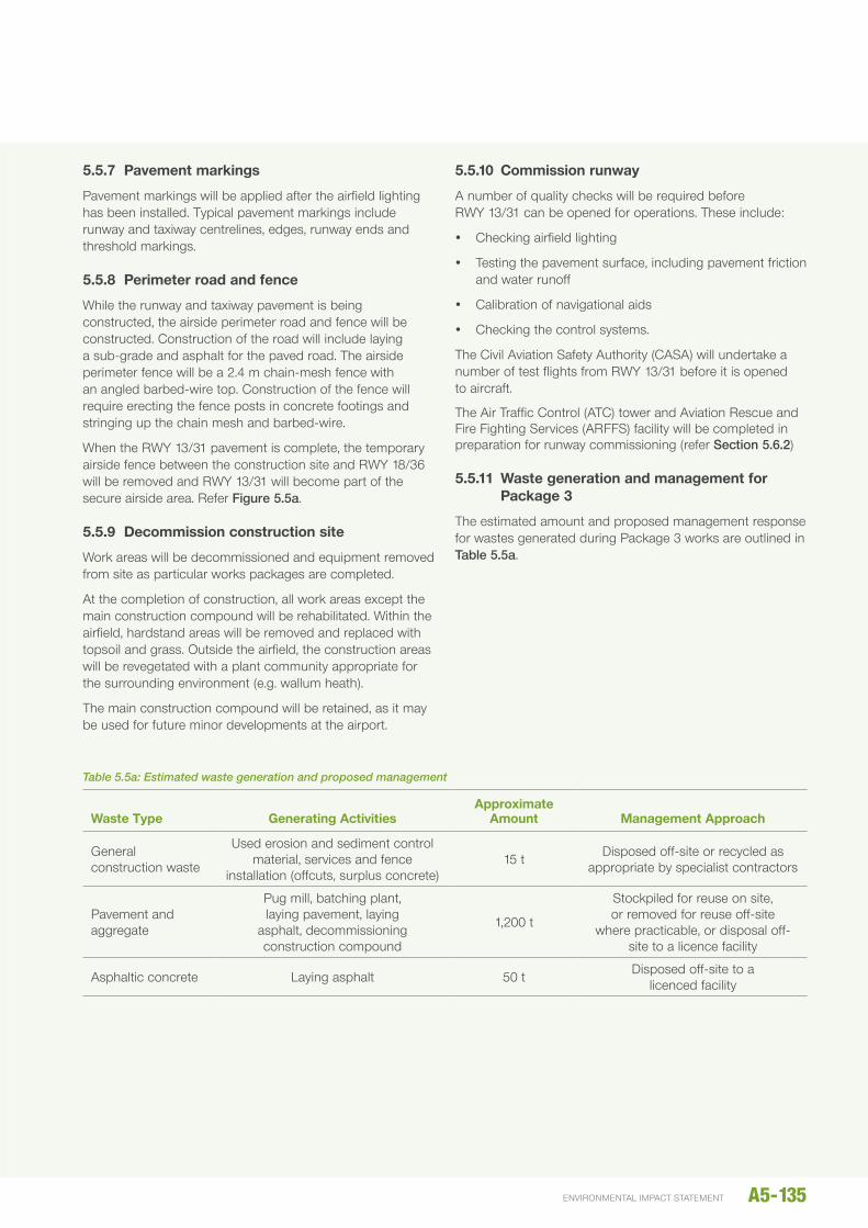
5.5.7 Pavement markings
Pavement markings will be applied after the airfield lighting has been installed. Typical pavement markings include runway and taxiway centrelines, edges, runway ends and threshold markings.
5.5.8 Perimeter road and fence
While the runway and taxiway pavement is being constructed, the airside perimeter road and fence will be constructed. Construction of the road will include laying a sub-grade and asphalt for the paved road. The airside perimeter fence will be a 2.4 m chain-mesh fence with an angled barbed-wire top. Construction of the fence will require erecting the fence posts in concrete footings and stringing up the chain mesh and barbed-wire.
When the RWY 13/31 pavement is complete, the temporary airside fence between the construction site and RWY 18/36 will be removed and RWY 13/31 will become part of the secure airside area. Refer Figure 5.5a.
5.5.9 decommission construction site
Work areas will be decommissioned and equipment removed from site as particular works packages are completed.
At the completion of construction, all work areas except the main construction compound will be rehabilitated. Within the airfield, hardstand areas will be removed and replaced with topsoil and grass. Outside the airfield, the construction areas will be revegetated with a plant community appropriate for the surrounding environment (e.g. wallum heath).
The main construction compound will be retained, as it may be used for future minor developments at the airport.
5.5.10 Commission runway
A number of quality checks will be required before RWY 13/31 can be opened for operations. These include:
y Checking airfield lighting
y Testing the pavement surface, including pavement friction and water runoff
y Calibration of navigational aids
y Checking the control systems.
The Civil Aviation Safety Authority (CASA) will undertake a number of test flights from RWY 13/31 before it is opened to aircraft.
The Air Traffic Control (ATC) tower and Aviation Rescue and Fire Fighting Services (ARFFS) facility will be completed in preparation for runway commissioning (refer Section 5.6.2)
5.5.11 Waste generation and management for Package 3
The estimated amount and proposed management response for wastes generated during Package 3 works are outlined in Table 5.5a.
Table 5.5a: Estimated waste generation and proposed management
Waste Type Generating ActivitiesApproximate
Amount Management Approach
General construction waste
used erosion and sediment control material, services and fence
installation (offcuts, surplus concrete)15 t Disposed off-site or recycled as
appropriate by specialist contractors
Pavement and aggregate
Pug mill, batching plant, laying pavement, laying
asphalt, decommissioning construction compound
1,200 t
Stockpiled for reuse on site, or removed for reuse off-site
where practicable, or disposal off-site to a licence facility
Asphaltic concrete Laying asphalt 50 t Disposed off-site to a licenced facility
A5-135environmental impact statement
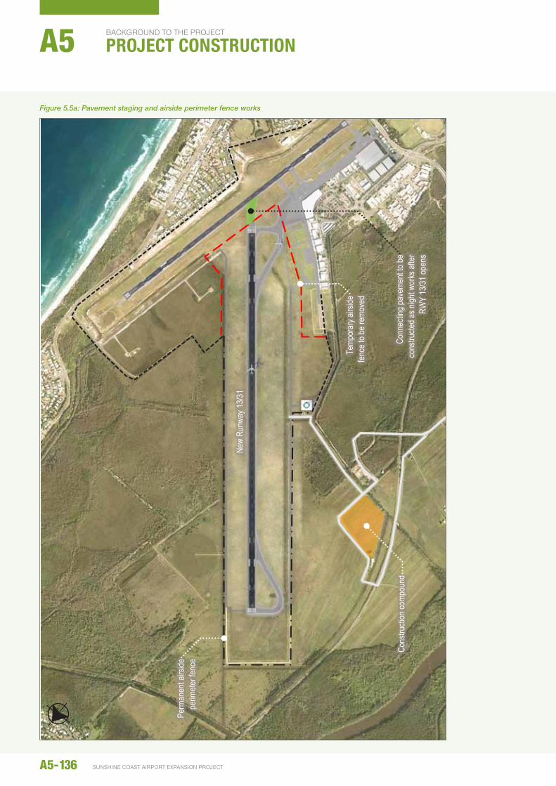
A5-136 SUNSHINE COAST AIRPORT EXPANSION PROJECT
BACkGROunD TO The PROjeCT
PROJECT CONSTRUCTIONA5
Figure 5.5a: Pavement staging and airside perimeter fence works
19 J
uly
2014
\\a
ubne
1fp0
03\p
roje
cts\
proj
ects
\602
4859
4\6.
dra
ft do
cs\6
.1 re
ports
\resc
ope
repo
rts\0
02_c
onst
ruct
ion
met
hodo
logy
\imag
es\c
onst
ruct
ion
imag
es_2
0140
711.
docx
16
of 1
6
Figu
re 5
.6a:
Pav
emen
t sta
ging
and
airs
ide
perim
eter
fenc
e w
orks
New
Runw
ay 13
/31
Perm
anen
t airs
ide
perim
eter f
ence
Temp
orar
y airs
ide
fence
to be
remo
ved
Cons
tructi
on co
mpou
nd
Conn
ectin
g pav
emen
t to be
co
nstru
cted a
s nigh
t wor
ks af
ter
RWY
13/31
open
s
5.6 PACkAGE 4: BUILdING WORkS
5.6.1 Terminal upgrade
The upgrades to the existing terminal will include internal renovations and staged extensions.
The internal renovations will consist of basic building work, undertaken by building contractors.
The extensions will require the demolition of existing structures, including the existing baggage handling area, and construction of the new buildings. The building construction will include new foundations, building framework and internal fit out.
5.6.2 Air Traffic Control tower and Aviation Rescue and Fire Fighting Service facility
Airport Drive will be extended to provide access to the ATC tower and ARFFS facility. The paved road will be single lane each way. Construction activities will include earthworks to provide an appropriate platform for pavement construction. Water, sewer, telecommunication and power services will be installed along the road corridor.
Fill will be required for the ATC/ARFFS facility to provide a stable surface and flood immunity for the facility.
It is expected that sand that is pumped to site as part of the overall reclamation will be tracked from the proposed runway site to the ATC/ARFFS facility location, although other surplus fill from construction of the runway may be used as an alternative. The fill will be placed and compacted in layers to ensure a suitable surface for construction of the building.
Construction of the ATC/ARFFS facility will include typical building activities, including establishing foundations (which will be significant for the tower), building framework and internal fit out.
5.6.3 Waste generation and management for Package 4
The estimated amount and proposed management response for wastes generated during Package 4 works are outlined in Table 5.6a.
The use of recycled materials will be investigated during detailed design for the terminal upgrade and other building works.
Table 5.6a: Estimated waste generation and proposed management
Waste Type Generating ActivitiesApproximate
Amount Management Approach
General construction waste (concrete, timber, steel, etc.)
General building works 500 tDisposed off-site or recycled as appropriate by the building
contractor
A5-137environmental impact statement