back fill,grouting , shotcrete
DESCRIPTION
grouting & shotcreteTRANSCRIPT

GROUTING &
SHOTCRETE

Introduction There are three main phases in the “life” of an
underground mine where some form of grouting for the control of groundwater may be required:
1) Development & Commissioning – during the construction of shafts, surface drifts & preliminary underground developments to gain access to the ore body.
2) Production/Operations – dealing with groundwater problems at the production face and when driving additional underground roadways, shafts, etc.
3) “Shut-down” – initial sealing of shafts and roadways and continuing remedial work as necessary.
Within these general areas different forms of grouting will be required to solve the various groundwater problems that are encountered.

Purpose of GroutingAlthough grouting has a number of quite different applications, the main purpose is always to eliminate or reduce the flow of groundwater into an existing or proposed underground excavation. Grouting is only one of several methods of ground treatment for excluding water which have to be assessed on their respective merits for each situation. However, grouting does provide the benefits of a permanent or at least semi-permanent, ground treatment and the bonus of increased stability in some situations, as compared with purely temporary expedients such as dewatering and ground freezing.

Grouting Methods & materials Permeation Grouting
In permeation grouting the grout material penetrates the interconnected porous structure of the soil or rock which may compromise both the intergranular voids & the fissure network. Whilst in most instances the fissure permeability represents the major contribution to the total permeability of the ground and, hence the main agent for transmitting groundwater flow to the excavation, there are instances where intergranular permeability is equally important.

Hydrofracture Grouting In both intergranular and fissure the injection is
carried out at pressures insufficient to disturb the ground structure. The grout advances steadily displacing air and water outwards with the predominant direction of flow being that offering the least resistance, ie. the path of highest permeability. In some circumstances, usually in relatively shallow alluvials, it is permissible to use hydrofracture grouting where deliberate overpressuring is used to either widen existing fissures or create new fissures. This procedure has the advantage of rapidly creating direct access through low permeability ground to a more permeable and treatable zone from the widely spaced array of injection holes.

Squeeze GroutingThe squeeze grouting technique is
used to apply high pressures to the ground to squeeze out excess pore water and consolidate the unstable material by increasing its density and shear strength. Consolidation is achieved by either forming a grout “bulb” which does not penetrate the soil or preferably by deliberate hydrofracture using a grout of limited capability to penetrate far.
Shotcrete
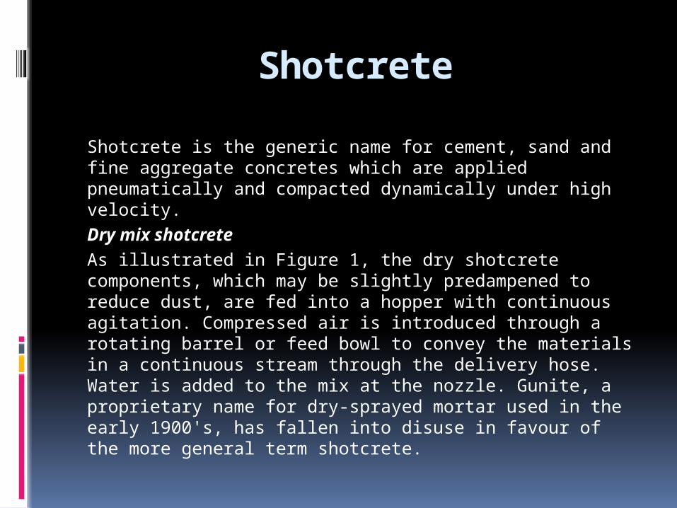
Shotcrete is the generic name for cement, sand and fine aggregate concretes which are applied pneumatically and compacted dynamically under high velocity.Dry mix shotcrete
As illustrated in Figure 1, the dry shotcrete components, which may be slightly predampened to reduce dust, are fed into a hopper with continuous agitation. Compressed air is introduced through a rotating barrel or feed bowl to convey the materials in a continuous stream through the delivery hose. Water is added to the mix at the nozzle. Gunite, a proprietary name for dry-sprayed mortar used in the early 1900's, has fallen into disuse in favour of the more general term shotcrete.

Wet mix shotcreteIn this case the shotcrete
components and the water are mixed (usually in a truck mounted mixer) before delivery into a positive displacement pumping unit, which then delivers the mix hydraulically to the nozzle where air is added to project the material onto the rock surface.

Shotcrete applications
The quality of the final shotcrete product is closely related to the application procedures used. These procedures include: surface preparation, nozzling technique, lighting, ventilation, communications, and crew training. Shotcrete should not be applied directly to a dry, dusty or frozen rock surface. The work area is usually sprayed with an air-water jet to remove loose rock and dust from the surface to be shot. The damp rock will create a good surface on which to bond the initial layer of shotcrete paste.

The nozzleman commonly starts low on the wall and moves the nozzle in small circles working his way up towards the back, or roof. Care must be taken to avoid applying fresh materials on top of rebound or oversprayed shotcrete.In fig. Note that the distance between the nozzle and the rock surface is approximately one metre.

It is essential that the air supply is consistent and has sufficient capacity to ensure the delivery of a steady stream of high velocity shotcrete to the rock face. Shooting distances are ideally about 1 to 1.5 metres. Holding the nozzle further fromthe rock face will result in a lower velocity flow of materials which leads to poor compaction and a higher proportion of rebound. A well-trained operator can produce excellent quality shotcrete manually, when the work area is well-lit and well-ventilated, and when the crew members are in good communication with each other using prescribed hand signals or voice activated FM radio headsets. However, this is a very tiring and uncomfortable job, especially for
overhead shooting, and compact robotic systems are increasingly being used to permit the operator to control the nozzle remotely.

Plastic pipes used to provide drainage for a shotcrete layer applied to a rock mass with water-bearing joints.

Rock massdescription
Rock massbehaviour
Supportrequirements
Shotcrete application
Massive metamorphic or igneous rock . Low stress conditions.
No spalling,slabbing or failure.
None. None.
Massive sedimentary rock. Low stress conditions.
Surfaces of some shales, siltstones, or claystones may slake as a result ofmoisture content change.
Sealing surface to prevent slaking.
Apply 25 mm thickness of plain shotcrete to permanent surfaces as soon as possible after excavation. Repair shotcrete damage due to blasting.
Massive rock with single wide fault or shear zone.
Fault gouge may beweak and erodibleand may causestability problems in adjacent jointedrock.
Provision of support and surface sealing in vicinity of weak fault of shear zone.
Remove weak material to a depth equal to width of fault or shear zone and grout rebar into adjacent sound rock. Weldmesh can be used if required to provide temporary rockfall support. Fill void with plain shotcrete. Extend steel fibre reinforced shotcrete laterally for at least width of gougezone.

Rock massdescription
Rock massbehaviour
Supportrequirements
Shotcrete application
Massivemetamorphic or igneous rock. High stressconditions.
Surface slabbing,spalling andPossible rockburstdamage.
Retention of broken rock and control of rock mass dilation.
Apply 50 mm shotcrete over weldmeshanchored behind bolt faceplates,or apply 50 mm of steel fibre reinforced shotcrete on rock and install rockbolts with faceplates; then apply second 25 mm shotcrete layer.Extend shotcrete application down sidewalls where required.
Massivesedimentary rock. High stress conditions.
Surface slabbing,spalling andPossible squeezingin shales and softrocks.
Retention of broken rock and control of squeezing.
Apply 75 mm layer of fibre reinforcedshotcrete directly on clean rock.Rockbolts or dowels are also neededfor additional support.
Apply 75 mm layer of fibre reinforcedshotcrete directly on clean rock.Rockbolts or dowels are also needed for additional support.
Potential for wedges or blocks to fall or slide due to gravity loading.
Provision of support in addition to thatavailable fromrockbolts or cables.
Apply 50 mm of steel fibre reinforcedshotcrete to rock surfaces on whichjoint traces are exposed.

Rock massdescription
Rock massbehaviour
Supportrequirements
Shotcrete application
Sedimentary rockwith a few widelyspaced beddingplanes and joints.Low stressconditions.
Potential for wedgesor blocks to fall orslide due to gravityloading. Bedding plane exposures maydeteriorate in time.
Provision of supportin addition to thatavailable from rockbolts or cables.Sealing of weak bedding plane exposures.
Apply 50 mm of steel fibre reinforced shotcrete on rock surface on which discontinuity traces are exposed,with particular attention to bedding plane traces.
Jointed metamorphic origneous rock.High stressconditions.
Combined structural and stress controlled failures around opening boundary.
Retention of brokenrock and control ofrock mass dilation.
Apply 75 mm plain shotcrete overweldmesh anchored behind boltfaceplates or apply 75 mm of steelfibre reinforced shotcrete on rock,install rockbolts with faceplates and then apply second 25 mm shotcrete layer Thicker shotcrete layers may be required at high stress concentrations.
Bedded and jointedweak sedimentaryrock. High stressconditions.
Slabbing, spallingand possiblysqueezing.
Control of rock massfailure and squeezing.
Apply 75 mm of steel fibre reinforced shotcrete to clean rock surfaces as soon as possible, install rockbolts, with faceplates, through shotcrete, apply second 75 mm shotcrete layer.

Rock massdescription
Rock massbehaviour
Supportrequirements
Shotcrete application
Highly jointedmetamorphic origneous rock.Low stressconditions.
Ravelling of smallwedges and blocksdefined byintersecting joints.
Prevention ofProgressive ravelling.
Apply 50 mm of steel fibre reinforcedshotcrete on clean rock surface in roofof excavation. Rockbolts or dowels may be needed for additional support for large blocks.
Highly jointed and bedded sedimentaryrock. Low stressconditions.
Bed separation inwide spanexcavations andravelling of bedding traces in inclined faces.
Control of bedseparation andravelling.
Rockbolts or dowels required to control bed separation. Apply 75 mm of fibre reinforcedshotcrete to bedding plane traces before bolting.
Heavily jointedigneous ormetamorphic rock, conglomerates or cemented rockfill. High stressconditions.
Squeezing and'plastic' flow of rock mass aroundopening.
Control of rock mass failure and dilation.
Apply 100 mm of steel fibre reinforcedshotcrete as soon as possible and install rockbolts, with face-plates, through shotcrete. Apply additional 50 mm of shotcrete if required. Extend support down sidewalls if necessary.

Rock massdescription
Rock massbehaviour
Supportrequirements
Shotcrete application
Heavily jointedsedimentary rockwith clay coatedsurfaces.High stressconditions.
Squeezing and'plastic' flow of rockmass aroundopening. Clay richrocks may swell.
Control of rock massfailure and dilation.
Apply 50 mm of steel fibre reinforcedshotcrete as soon as possible, installlattice girders or light steel sets, withinvert struts where required, then moresteel fibre reinforced shotcrete to coversets or girders. Forepoling or spilingmay be required to stabilise face aheadof excavation. Gaps may be left infinal shotcrete to allow for movementresulting from squeezing or swelling.Gap should be closed once opening isstable.
Mild rockburstconditions inmassive rocksubjected to highstress conditions.
Spalling, slabbingand mild rockbursts.
Retention of brokenrock and control offailure propagation.
Apply 50 to 100 mm of shotcrete overmesh or cable lacing which is firmlyattached to the rock surface by meansof yielding rockbolts or cablebolts.

When designing a shotcrete program the following issues need to taken into consideration:-
· Amount of shotcreting required;· Shotcrete strength;· Shotcrete thickness;· Presence of groundwater (eg. quantity,
chemistry, pressure);Surface Rock Support for Underground Mines 7Code of Practice· Need for drainage of groundwater from behind
the shotcrete;· Water quality (potable);· Type of shotcrete mix (wet or dry);

· Use of microsilica;· Admixtures (plasticisers, etc);· Accelerators (for wet mix);· Fibre reinforcement;· Curing (external or internal);· Testing and monitoring;· Correct shotcrete application.

CODE OF TIMBERING

CODE OF TIMBERING RULES
CODE OF TIMBERING RULE ARE VARIES IN DIFFERENT –DIFFERENT METHOD.
1.FOR OPEN STOPE AREAS2.FOR BREAST STOPING3. FOR ROOM AND PILLAR4.FOR UNDERGROUND MANAGEMENT
MINESa. FLAT CUT AND FILL METHODb. SQUARE SET METHOD5.FOR UNDERGROUND URANIUM MINES

FOR OPEN STOPE AREAS
1. Stulls shall be set at a maximum of 2 metres between the same row and also between row of stulls.the front row is not more than 4.2 metres from the face.
2. Cogs or pigstys shall be set at all entrance to the stoping areas and also at a interval of not more than 4.5 metres for working height 3 metres.
for drives in ore body:-3.Within a distance of 30 metres from the block ,stulls shall be set at a
maximum interval of 1.5 metres between row and same row in all the drives and winzes.
4.Cogs and pigysts shall be set at all junction of the drives and winzes within a distance of 30 metres from the block under extraction where height is more than 3 metres ,8 closely set stulls may be used in place of stulls.

5. The width of ledge used for the top and foot of the stulls shall not be less than the diameter of the prop.
6.Where floor ore is being taken ,stulls shall not be left on the strumps and the shorter stulls shall immediately be replaced with longer stulls.
7.The timber used for the construction of the cogs or pigysts shall not be less than 1.2 metres in length and shall have at least two opposite side joggeled flat to provide suitable bearing surface.

8.cogs and pigysts and stulls shall be kept tight against the hanging wall and set on a properly formed base.
9.additional support is erected when necessary.

FOR BREAST STOPING
1. Stulls shall be set at a maximum interval of 1.5 metres between stulls in the same row and a maximum interval of 2.4 metres between the row of the stulls .the front row being not more than 3.9 metre from the face.
2. The stulls in two adjacent row shall be staggered.
3. The planes of faults or slips and hanging or parted frames shall be substantially supported by cogs ,pigysts,chockmats or stulls before person are employed at the face.
4.Cogs or chockmates shall be set at interval of not more than 4.5 metres in the area under actual extraction.5.The support in the area beyod 18 metres from the face may be withdraw if they do not show any sign of weighting.6.The abondened area beyond 18 metres of the face shall be kept fenced and no person shall be allowed to go beyond the fencing.
For drives,winzes and raises:
7. The DRIVES,WINZES AND RAISES WITHIN A DISTANCE OF 30 metres from the block under extraction shall be supported by one or more row of stulls or bars at a maximum interval of 3 metres in the same row and a maximum interval of 3 metres in the same row of stulls.8.Cogs or chockmates shall be set at all junction of the drive,winze and raise within a distance of 30 metres from the block under extraction.9.The width of ledge out for the top and foot of the stulls shall not be less the diametres of stulls.10.cogs,pigysts,chockmates ,bars,and stulls shall be kept tight against the roof and set on a properly formed base.

For room and pillar method
1.The working area of stope shall be supported by row of roof bolts.
2.Roof bolts shall be set at a maximum of 1.2 m interval between the roof bolts in the same row and a maximum interval of 1.2 m between the two row.
3.Roof bolts in adjacent shall be staggered.4.At no time shall the front row of roof bolts
be more than 3.0 metres from the face before next round of blasting is taken.

5.The roof bolts may be withdrawn during the course of filling.
Post pillar method::
6.support of the working area shall be provided with roof bolts and pillars.
7.Roof bolts shall be set at a maximum interval of 1.5 metre between roof bolts in the same row and 1.5 metres between the two rows.
8.At no time shall the front row of rock bolts be more than 5 metres from the face before it is advanced any further.
9.The roof bolt may with drawn during the course of filling.

4.Flat cut and fill method
1.The back of all cut and fill method stopes shall be supported with pigysts at a distance of 3 m between pigysts in the same row and 1.8 m between the last row of pigysts and the wall ,nearest row of
pigysts being not more than 4 m from the face.2.Between the face and the last row of pigysts ,the back shall be
supported with props at interval of not more than 1.5 m.
3.The lids and wedge ,used with the prop shall have a width not less than the diameter of the prop,a thickness of not less than 6 cm,and a length of not less than .5 m.
4. The prop shall not set on packing.a flat base piece ,not less than 5 cm thick, 25 cm wide,and .75 m long long shall be used.
5.The timber used for the construction of pigysts shall not be less than 1.2 m in length and at least two opposite sides joggled flat so as to provide a suitable bearing surface.
6.Weak patches of back and hanging wall shall be supported by additional support of pigysts and props.

Square set method
Where the ore bed is weak and friable so the stope block is not self supporting .it shall be systematically supported with square set of the approved size.
Erection of sets:-
a.As the set used for cap butting sets ,the cap shall be laid at right angles to the general strike of the ore body ,because it has to give maximum support of the walls.
b.Durind dressing .timber form a proper joint.
c.All open dressing shall be tightly blocked and wedged to prevent sideway movement.
d.Side lagging board shall be placed from post to post and the gap between the lagging board and the walls shall be tightly packed either with the junks or fill material.

Stengthing of set :-
a.Angle braces –they shall be fixed to reinforce the sets against the side pressure.
b.Doubling will be done in necessary condition.
Underhand square set:-
1.Before taking up underhanding operation a minimum of two numbers hanger shall be fixed on each horizontal member.
b.A pair of stringers shall be erected before a set is underhand.
c.As soon as possible,additional support with pick-up of boom shall be provided.
d.Underhanding of more than three sets in a row shall be carried in steeper down pattern and with overlapping pattern of stringers.

5.FOR UNDERGROUND URANIUM MINES
Cut and fill stope:- 1.after each round of blasting in the stope the back shall be
througly dressed. 2 the maximum span between the fill and the back shall not
exceed 4.5 m at any time. 3 the bolt shall be fixed in the back and hanging wall of the stope. 4 the length of bolt shall be not less than 1.5 m. 5 the back shall be supported by the bolt at 2*2 m interval.
Open stopes:-
1. Stulls shall be set at a maximum interval of 2 m between the rows of stulls,the front row being not more than 4.2 m from the face.
2. Cogs and pigysts shall be set at all entrances to the stoping areas and also at interval of not more than 4.5 m in the area under stoping where working height is 3 m or less.

BACK FILL

BACK FILL INTRODUCTION
Backfill is an increasingly important component of underground mining operations around the world. This will give a brief overview of the current application of mining with backfill technology, focusing on this operations. In the context of this summit, the disposal of mine tailings underground not only reduces the environmental impact but also provides the base of an engineering material which can be used to improve both the ground conditions and the economics of mining. backfill systems can significantly enhance a mining operation. By contrast, badly engineered and poorly run backfill can be a serious impediment to the mine and, worst of all, compromise safety.

Back fill Backfill refers to any waste material that is placed into voids mined
underground for the purposes of either disposal or to perform some engineering function.
Waste materials used include waste development rock, deslimed and whole mill tailings, quarried and crushed aggregate, and alluvial sand. Other exotic backfill types used overseas includeice and salt.
The waste materials are often placed with very lean cement or other pozzolanic binders to improve the strength properties.
Gravity based delivery methods are utilised for slurry based systems with the dense tailings slurry being delivered by pipeline to the disposal point in the stope.
These pipelines can range from low pressure (less than 1MPa) turbulent flow systems for deslimed slurries to high pressure (greater than 5MPa) laminar flow systems for pastefill.
Sometimes backfill only acts as a void filler and needs only sufficient strength to preventany form of remobilisation.
Where backfill is used as an engineering material it requires sufficient strength be exposed by ore pillar mining in tall vertical faces or undercuts.
Lean cement addition is used to generate unconfined compressive strengths ranging from 0.5 to 4 mpa.

The other essential requirement is that backfill must be of low cost. Typical costs ofbackfill range from $2 to $20 per cubic metre, depending on the duty required.
These costs can be a significant contribution to the operating costs of the mine.
Where cemented backfills are used, these costs tend to be between 10 and 20% of the total operating cost of the mine and cement represents up to 75% of that cost.
8 BACKFILL TYPES AND MATERIALS
The three back fill types that will be discussed are:· Hydraulic backfill : Deslimed mill tailings slurries, with densities raised toover 70%Cw (solids by weight). The coarser fractions areplaced underground as hydraulic backfill and the slimes rejected to the surface dam.
· Paste backfill : - Total mill tailings filtered or thickened to around 80%Cwto which cement and water is then added to achieve therequired rheological and strength characteristics. Anyrejects to the dam are at the full tailings sizing range.
· Rock backfill :- Waste rock from surface or underground and crushed toa typical top size of around 40mm. This can be placed asis or with cemented hydraulic backfill slurry or cementwater slurry.

HYDRAULIC BACKFILL 1.Hydraulic backfill is produced by cycloning of mill tailings slurries to produce a
coarse dense underflow.Typical specifications of hydraulic backfill are: Not more than 10% by weight of size fraction less than 10m (micrometres) in size. This ensures that acceptable permeability of the placed fill is achieved.
2.Slurry density is greater than 70%Cw (solids by weight). The high densityminimises the drainage of transport water. The target density is a function ofparticle specific gravity and the controlling parameter is %Cv (solids by volume)which balances the requirement to transport the slurry without plugging the lineand excess drainage water. 3. The practical range is between 45%Cv and 50%Cv. 4. Hydraulic backfill slurries are transported by gravity through boreholes and
pipelines tothe stopes. 5. The slurry enters the stope and the solid particles consolidate rapidly. 6.The excess transport water in the slurry will initially pond above the current solids
layer, butunder the influence of gravity will commence on a generally vertical drainage path.
downwards. The rate of drainage is a function of the permeability of the backfill and thedriving head. The quantity of water that will drain is a function of the initial slurry densityand the residual moisture content of the backfill. The quantity of drainage resulting fromslurry densities of around 70%Cw is as little as a quarter of the drainage resulting from55%Cw slurries.Free draining hydraulic backfill has a typical porosity of around 50%, can be walked on ina few hours and is trafficable within 24 hours.Where the hydraulic fill is to be exposed, cement addition rates of around 6% are typicallyrequired and this will result in unconfined compressive strengths of greater than 750kPawithin 28 days. Higher strengths and faster curing can be achieved by adding extracement.At Mount Isa cemented hydraulic backfill consisting of 3% OPC, 6% ground furnace slag(to produce 6% equivalent cement) and 91% deslimed tails are routinely exposed overwidths of 40 metres and over 100 metres high

BULK AND EXPOSABLE BACKFILLS There are several ways of classifying backfills, both
by type and by function. An essentialdistinction from the design point of
view is whether the backfill is to be used essentially asvoid filler or will it be exposed by future mining of ore pillars.
Prior to the advent of pastebackfill systems this classification could be described as cemented or uncemented.
However, paste needs small quantities of cement in all backfill placed to eliminate the riskof liquefaction, therefore this classification is no longer appropriate.

·Bulk Backfill :- Waste materials placed into a stope for the purpose ofdisposal and or to provide confinement to surrounding rockwalls. The upper surface can be used as a working platform.Resistance to rock wall closure effected by intergranularfriction of the backfill.
·Exposable Backfill:- Engineered materials with cement and or other binder addedwhich has sufficient cohesion to support its self weight whenexposed either as a vertical face or in an overhang by theblasting of adjacent pillar ore

Disadvantages:-
There are two significant disadvantages to hydraulic backfill. 1. The first is that permeable barricades must be designed and
constructed to retain the backfill and permit the free drainage of excess transport water. Barricades are commonly built with porous and take a two man crew between 2 to 3 shifts to complete. This occurs as a critical path activity between the completion of production in a stope and the commencement of filling.
2. second disadvantage :- is the management of water in the fill and the pump this water out of the mine. When controls on slurry density are lax, excessive water can result in ponding of water in the stopes, which can lead to the development of erosion pipes and cause barricade failure. In calendar 1997, there were nine such incidents; in1998 there have been none reported. The risk of barricade failure and the consequences of a backfill inrush are a serious safety issue that requires management focus to ensure that the risk factors are managed. The guidelines of fines removal and placement at high slurry densities eliminate those risk factors.

Conclusion:- Backfill is an increasingly important component of underground mining operations. Asmines get deeper, the need for improved ground control and maximised resource recoveryis essential to their safe and economic operation. The total management of waste materialsat the mine site needs to be engineered into the design of the mine. Increasingly,environmental considerations are showing that improved waste management procedureshave benefits to the mining operations. Regulators are increasingly requiring the priorplanning of final site restoration as part of the initial mine plan.Mining with backfill technology helps mining companies achieve many of these goals.Backfill minimises the total quantities of materials to be managed on surface. The wastematerials can be engineered to give support and strength properties that improve thesafety of the mining operations and the economics of the enterprise.The technology of backfilling enables a wide range of engineering solutions to particularmine sites and their unique sets of problems and opportunities. There is not one universalsolution to backfill or mine tailings disposal systems.AMC predicts that there will be many more developments yet to be seen in this rapidlyemerging area of technology.

ROCK BOLTS
•IntroductionRockbolts and dowels have been used for many years for the support of underground excavations and a wide variety of bolt and dowel types have been developed to meet different needs which arise in mining and civil engineering.Rockbolts generally consists of plain steel rods with a mechanical or chemical anchor at on end and a face plate & nut at the other end. They are always tensioned after installation. For short term applications the bolts are generally left ungrouted. For more permanent applications or in rock in which corrosive groudwater is present, the space between the rock& bolt can be filled with cement & resin grout.

Dowels or anchor bars generally consist of deformed steel bars which are grouted into the rock. Tensioning is not possible and the load in the dowels is generated by movements in the rock mass. In order to be effective, dowels have to be installedbefore significant movement in the rock mass has taken place. Figure 1 illustrates a number of typical rockbolt and dowel applications that can be used to control different types of failure that occur in rock masses around underground openings.

Figure 1: Typical rockbolt and dowel applications to control different types of rock mass failure during tunnel driving.

TYPES
MECHANICALLY ANCHORED ROCKBOLTS
Expansion shell rockbolt anchors come in a wide variety of styles but the basic principle of operation is the same in all of these anchors. The components of a typical expansion shell anchor are a tapered cone with an internal thread and a pair of wedges held in place by a bail. The cone is screwed onto the threaded end of the bolt and the entire assembly is inserted into the hole that has been drilled to receive the rockbolt. The length of the hole should be at least 100 mm longer than the bolt otherwise the bail will be dislodged by being forced against the end of the hole. Once the assembly is in place, a sharp pull on the end of the bolt will seat the anchor. Tightening the bolt will force the cone further into the wedge thereby increasing the anchor force.

At the other end of the rockbolt from the anchor, a fixed head or threaded end and nut system can be used. In either case, some form of faceplate is required to distribute the load from the bolt onto the rock face. In addition, a tapered washer or conical seat is needed to compensate for the fact that the rock face is very seldom at right angles to the bolt. A wide variety of faceplates and tapered or domed washers are available from rockbolt suppliers.Tensioning of rockbolts is important to ensure that all of the components are in contact and that a positive force is applied to the rock. In the case of light 'safety‘ bolts, the amount of tension applied is not critical and tightening the nut with a conventional wrench or with a pneumatic torque wrench is adequate. Where the bolts are required to carry a significant load, it is generally recommended that a tension of approximately 70% of the capacity of the bolt be installed initially. This provides a known load with a reserve in case of additional load being induced by displacements in the rock mass.

Expansion shell anchored rockbolt
Steel rod diameter: 17.28 mm Ultimate tensile strength of bolt shank: approximately 12.7
tonnes Expansion shell anchor: Bail type three wedge anchor At the pre-load of 2.25 tonnes, no deformation of the face
plate. At a load of 4 tonnes, the face plate has deformed 9.5 mm and
is completely flat, the bolt shank has deformed an additional 3.5 mm giving a total deformation of 13 mm at 4tonnes load.
Failure initiates at a load of 8 tonnes and a deformation of 25 mm with progressive failure of the expansion shell anchor in which the cone is pulled through the wedge.
Maximum load is 9 tonnes at a deformation of 35 mm.
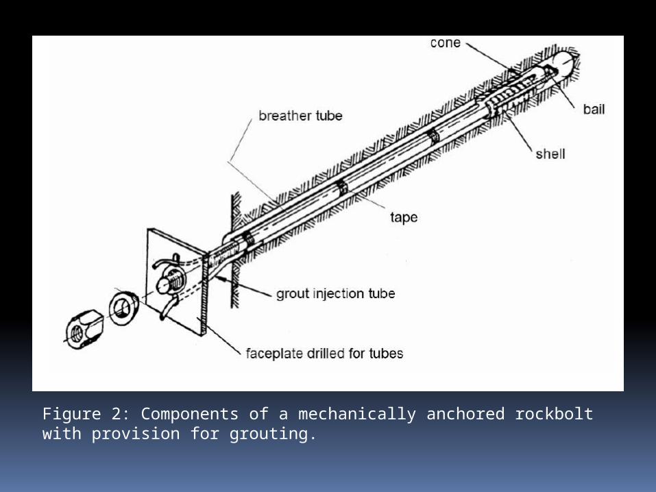
Figure 2: Components of a mechanically anchored rockbolt with provision for grouting.

RESIN ANCHORED ROCKBOLTS
A typical resin product is made up of two component cartridges containing a resin and a catalyst in separate compartments. The cartridges are pushed to the end of the drill hole ahead of the bolt rod that is then spun into the resin cartridges by the drill. The plastic sheath of the cartridges is broken and the resin and catalyst mixed by this spinning action. Setting of the resin occurs within a few minutes (depending upon the specifications of the resin mix) and a very strong anchor is created.Resin grouted steel rebar•Steel rebar diameter: 20 mm•Ultimate tensile strength of steel rebar: 18 tonnes•Faceplate: flat plate•Borehole diameter: 32 mm•Resin grout: Five 580 mm long, 27 mm diameter polyester resin cartridges. Curing time 60 minutes. Mixed by rotating rebar through cartridges in the borehole

•At a load of 15 tonnes and an elastic deformation of about 1.5 mm, a sudden load drop is characteristic of hot rolled rebar steel. Maximum load is 18 tonnes at a deformation of 20 mm.• The resin is stronger than the cement grout and local fracturing and bond failure in and near the joint is limited as compared with the cement grouted rebar, leading to a reduced ultimate displacement at rebar failure.
Typical set-up for creating a resin anchored and grouted rockbolt.