ba ds ws15 en usa - hilti.com · grounded tools must be plugged into an outlet prop-erly installed...
TRANSCRIPT

Operating instructions en
DS WS15
C US
Printed: 08.07.2013 | Doc-Nr: PUB / 5069750 / 000 / 01

2
Contents Page
1. General safety rules 4
2. Specific safety rules and symbols 6
3. Functional description 13
4. Assembly 22
5. Operation 32
6. Maintenance 34
7. Accessories 38
8. Troubleshooting 42
9. Manufacturer's warranty – tools 48
10. Disposal 48
ORIGINAL OPERATING INSTRUCTIONS
DS WS15 3×480V electric wire saw
It is essential that the operating instructions are readbefore the machine is operated for the first time.Always keep these operating instructions togetherwith the machine.Ensure that the operating instructions are with themachine when it is given to other persons.
DANGERDraws attention to imminent danger that will lead toserious bodily injury or fatality.WARNINGDraws attention to a potentially dangerous situation thatcould lead to serious personal injury or fatality.CAUTIONDraws attention to a potentially dangerous situation thatcould lead to slight personal injury or damage to theequipment or other property.NOTEDraws attention to an instruction or other useful infor-mation.
Printed: 08.07.2013 | Doc-Nr: PUB / 5069750 / 000 / 01

3
� Drive and storage unit� Control unit� Air compressor� Pressure hoses 2×23 ft, 1x3.3 ft (2×7 m, 1×1 m) � Single pair pulley (2 pcs)� Water supply – long� Water supply – flexible Water hose 2×33 ft (2×10 m) Tool set DS-WS UL� Extension cord 33 ft (10 m)� Wire guard set DSW-WG
�
�
�
�
�
�
�
�
�
Printed: 08.07.2013 | Doc-Nr: PUB / 5069750 / 000 / 01
4
General safety rules
1. General safety rules
WARNING! Read and understand all instructions.Failure to follow all instructions listed below may resultin electric shock, fire and/or serious personal injury.
SAVE THESE INSTRUCTIONS
Work AreaKeep your work area clean and well lit. Clutteredbenches and dark areas invite accidents.Do not operate power tools in explosive atmos-pheres, such as in the presence of flammable liquids, gases, or dust. Power tools create sparkswhich may ignite the dust or fumes.Keep bystanders, children and visitors away whileoperating a power tool. Distractions can cause you tolose control.
Electrical SafetyGrounded tools must be plugged into an outlet prop-erly installed and grounded in accordance with allcodes and ordinances. Never remove the groundingprong or modify the plug in any way. Do not use anyadaptor plugs. Check with a qualified electrician if youare in doubt as to whether the outlet is properly ground-ed. If the tools should electrically malfunction or breakdown, grounding provides a low resistance path to car-ry electricity away from the user.Applicable only to Class I (grounded) tools.
Avoid body contact with grounded surfaces such aspipes, radiators, ranges and refrigerators. There is anincreased risk of electric shock if your body is ground-ed.
Don’t expose power tools to rain or wet con di tions.Water entering a power tool will increase the risk ofelectric shock.
Do not abuse the cord. Never use the cord to carrythe tools or pull the plug from an outlet. Keep cordaway from heat, oil, sharp edges or moving parts. Replace damaged cords immediately. Damagedcords increase the risk of electric shock.
When operating a power tool outside, use an outdoorextension cord marked «W-A» or «W». These cordsare rated for outdoor use and reduce the risk of electricshock.
1.3
1.2
1.1
Personal Safety
Stay alert, watch what you are doing and use com-mon sense when operating a power tool. Do not usea tool while tired or under the influence of drugs, al-cohol, or medication. A moment of inattention whileoperating power tools may result in serious personalinjury.
Dress properly. Do not wear loose clothing or jewelry. Contain long hair. Keep your hair, clothing,and gloves away from moving parts. Loose clothes,jewelry, or long hair can be caught in moving parts.
Avoid accidental starting. Be sure switch is off beforeplugging in. Carrying tools with your finger on theswitch or plugging in tools that have the switch on in-vites accidents.
Remove adjusting keys or wrenches before turning the tool on. A wrench or a key that is left attached to a rotating part of the tool may result in per-sonal injury.
Do not overreach. Keep proper footing and balance atall times. Proper footing and balance enables bettercontrol of the tool in unexpected situations.
Use safety equipment. Always wear eye protection.Dust mask, non-skid safety shoes, hard hat, or hea ringprotection must be used for appropriate conditions.
Tool Use and CareUse clamps or other practical way to secure and sup-port the workpiece to a stable platform. Holding thework by hand or against your body is unstable and maylead to loss of control.Do not force tool. Use the correct tool for your appli-cation. The correct tool will do the job better and saferat the rate for which it is designed.Do not use tool if the switch does not turn it on or off.Any tool that cannot be controlled with the switch isdangerous and must be repaired.Disconnect the plug from the power source be foremaking any adjustments, changing accessories, orstoring the tool. Such preventive safety measures re-duce the risk of starting the tool accidentally.
1.5
1.4
Printed: 08.07.2013 | Doc-Nr: PUB / 5069750 / 000 / 01

5
Store idle tools out of reach of children and other un-trained persons. Tools are dangerous in the hands ofuntrained users.Maintain tools with care. Keep cutting tools sharpand clean. Properly maintained tools with sharp cutting edges are less likely to bind and are easier tocontrol. Check for misalignment or binding of moving parts,breakage of parts and any other condition that mayaffect the tools operation. If damaged, have the toolserviced before using. Many accidents are caused bypoorly maintained tools.Use only accessories that are recommended by themanufacturer for your model. Accessories that may besuitable for one tool may become hazardous whenused on another tool.
ServiceTool service must be performed only by qualified re-pair personnel. Service or maintenance performed byunqualified personnel could result in a risk of injury.When servicing a tool, use only identical replace-ment parts. Follow instructions in the Maintenancesection of this manual. Use of unauthorized parts orfailure to follow Maintenance Instructions may create arisk of electric shock or injury.
1.6
General safety rules
Printed: 08.07.2013 | Doc-Nr: PUB / 5069750 / 000 / 01

6
Specific safety rules and symbols
2. Specific safety rules and symbols
WARNINGFailure to observe the instructions listed below maylead to potentially fatal injury and serious damage toproperty or equipment.
Proper organization of the work area
a) Approval must be obtained from the site engineeror architect prior to beginning drilling or sawingwork. Drilling or sawing work on buildings and oth-er structures may influence the statics of the struc-ture, especially when steel reinforcing bars or load-bearing components are cut through.
b) Ensure that the workplace is well ventilated. Expo-sure to dust at a poorly ventilated workplace mayresult in damage to the health.
c) In order to avoid injury and to prevent the diamondwire becoming trapped or jammed, steel wedgesand/or supports must be used to prevent uncon-trolled movement of parts of the structure being cut.
d) Ensure that adequately-sized supports are correct-ly installed so that the remaining structure maintainsits stability after completion of the cutting work andremoval of the part cut away.
e) Never loiter in the vicinity of loads suspended bycranes.
f) The area of the cut or the opening created by the cut-ting process must be safely and visibly cordoned offin order to avoid the possibility of persons falling.
g) Keep children away. Keep other persons away fromthe working area.
h) Do not allow other persons to touch the machine orthe extension cord.
i) To avoid presenting a tripping hazard, always ensurethat cables and hoses leading to the machine are laidflat on the floor.
j) Keep cables and hoses away from rotating parts.
2.1
k) In cooperation with the site engineer or architect,ensure that no gas, water, electricity or other supplylines are located in the cutting area. Any supply pipesor cables located close to the cutting area whichcould, for example, be damaged by falling objects,must be specially protected and, if necessary, switchedoff or temporarily taken out of service.
l) Ensure that the cooling water used is drained orextracted in a suitably controlled manner. Water thatis allowed to drain away or spray around in an uncon-trolled manner can lead to damage or accidents. Thefact that water could drain away into internal, hiddencavities, e.g. in brickwork or masonry, must also betaken into account.
m) Do not work from a ladder.
Safety measures at the danger areaa) Safety measures must be implemented in the area
where sawing is taking place so that operators andbystanders cannot be injured or property damagedby a broken sawing wire or debris that may fly offduring the sawing operation. Safety measures mustalso be implemented in the area not directly visibleto the operator, i.e. behind where sawing is takingplace.
b) Persons must NEVER enter the danger area whilesawing is in progress.
c) Always keep the free wire lengths between the dri-ve unit and object being cut as short as possible(max. 11.5 ft / 3.5 m) and mount guide pulleys atthe wire entry and exit points in order to reduce therisk of whiplash in the event of wire breakage. Thewhiplash effect causes great acceleration of the saw-ing wire, resulting in parts of the wire lashing out orflying off with great force.
d) Make sure there are no objects such as scaffoldingetc. within the wire whiplash area. In the event ofwire breakage, the whiplashing end of the wire maybe deflected in an unexpected direction by suchobjects.
e) The danger area has a radius of at least twice thefree length of wire that would be unleashed in the eventof wire breakage (shown in yellow) and also includesthe areas in the extended axes of the direction in which
2.2
Printed: 08.07.2013 | Doc-Nr: PUB / 5069750 / 000 / 01

7
Specific safety rules and symbols
the wire is running (shown in gray). The danger areacannot be limited unless suitable means of protectionare employed (protective walls, curtains or wire guardsetc.). The protective devices must be arranged andmounted in a way that stops the wire lashing out in theevent of wire breakage and reliably prevents objects orfragments flying off.
f) The operator is responsible for cordoning off thearea. If necessary, safety personnel must be postedto prevent access to a wide area around the workplace.
g) When setting up and operating the saw system andwhen removing parts that have been cut away, alwaysensure that no persons are below the area in whichyou are working. Falling objects could cause seri-ous injury.
h) It is important to utilize the protective equipmentsupplied, an ask questions if unsure as to how it isproperly used.
General safety instructions
a) Use the right machine for the job. Do not use themachine for purposes for which it was not intend-ed. Use it only as directed and when in faultless con-dition.
b) Persons must NEVER enter the hazardous area whilesawing is in progress. The hazardous area extends toat least twice the radius of the length of wire that wouldbe unleashed in the event of the wire breaking andalso includes the area in the extended axis of the wire
2.3
tension side. The operator is responsible for cordon-ing off the area and restricting access. The hazardousarea may be entered only when the EMERGENCY STOPbutton is in the pressed-in position.Children must be instructed not to play with themachine.The machine is not intended for use by children, bydebilitated persons or those who have received noinstruction or training.
c) Use the machine, accessories and sawing wires etc., inaccordance with these instructions and in the mannerintended for the particular type of machine, taking intoaccount the working conditions and the work to be per-formed. Use of this machine for operations other thanthose intended could result in hazardous situations.
d) Never leave the machine unattended.e) Always disconnect the machine from the electric
supply when it is not in use (e.g. during breaksbetween working), before making adjustments, beforecarrying out care and maintenance and before chang-ing sawing wires. This safety precaution preventsthe machine starting unintentionally.
f) WARNING: Some dust created by grinding, sand-ing, cutting and drilling contains chemicals knownto cause cancer, birth defects, infertility or otherreproductive harm; or serious and permanent res-piratory or other injury. Some examples of thesechemicals are: lead from lead‐based paints, crys-talline silica from bricks, concrete and other mason-ry products and natural stone, arsenic and chromi-um from chemically‐treated lumber. Your risk fromthese exposures varies, depending on how often youdo this type of work. To reduce exposure to thesechemicals, the operator and bystanders shouldwork in a well‐ventilated area, work with approvedsafety equipment, such as respiratory protectionappropriate for the type of dust generated, anddesigned to filter out microscopic particles anddirect dust away from the face and body. Avoid pro-longed contact with dust. Wear protective clothingand wash exposed areas with soap and water. Allow-ing dust to get into your mouth, nose, eyes, or toremain on your skin may promote absorption of harm-ful chemicals.
g) Before use, the machine, the sawing wire and acces-sories must be checked carefully to ensure that allitems function faultlessly and as intended. Checkthat moving parts function correctly without stick-
Printed: 08.07.2013 | Doc-Nr: PUB / 5069750 / 000 / 01

8
Specific safety rules and symbols
ing and that no parts are damaged. All parts mustbe fitted correctly and fulfill all conditions necessaryfor correct operation of the machine. Damaged partsmust be repaired or replaced properly by an autho-rized service center.
h) Avoid skin contact with slurry.
i) Wear a protective mask during work that generatesdust, e.g. dry cutting. Connect a dust removal sys-tem. Cutting materials hazardous to the health (e.g.asbestos) is not permissible.
Electrical safety
a) Make sure that no gas, water, electricity or other sup-ply lines are located in the cutting area. Supply lineslocated close to the cutting area which could be dam-aged by falling parts, for instance, must be speciallyprotected and, if necessary, temporarily switched offetc.
b) Check the machine’s supply cord at regular intervalsand have it replaced by a qualified specialist if foundto be damaged. Check extension cords at regularintervals and replace them if found to be damaged.
c) Check the condition of the machine and its acces-sories. Do not operate the machine and its acces-sories if damage is found, if the machine is incom-plete or if its controls cannot be operated faultlessly.
d) Do not touch an electric cable that has been dam-aged while working. Switch off at the main switchand unplug the cable at the power outlet.
e) Damaged or faulty switches must be replaced at aHilti service center. Do not use the machine if it can-not be switched on and off correctly.
f) Connect the machine and its ancillary equipment onlyto a power source equipped with an earth conductorand ground fault circuit breaker (PRCD). Check thatthese items are in perfect working order before oper-ating the equipment. Install an earth/ground rod if agenerator is used.
g) Make sure that the mains voltage corresponds tothe specification given on the type plate.
h) Electric cables and their plug connectors must be
2.4
kept dry. When not in use, close power outlets withthe cover provided.
i) Use only extension cables which have an adequateconductor cross-section and are approved for theintended field of use. Do not work with extensioncables when they are rolled up. This can result in adrop in output at the equipment and may cause thecable to overheat.
j) Disconnect the power cable before beginning clean-ing and maintenance work or in the event of a lengthyinterruption between periods of operation.
k) Please note that certain components of the powerconverter retain an extremely dangerous (potential-ly fatal) high voltage for up to 10 minutes after dis-connection from the electric supply.
Requirements to be met by users
a) The wire saw system may be operated only by spe-cialists trained in concrete cutting techniques, referredto in the following as “operators”. These personsmust be familiar with the content of these operatinginstructions and must have been trained in their safeapplication by a Hilti specialist.
b) Stay alert, watch what you are doing and use com-mon sense when working. Do not use the equipmentwhen you are tired or under the influence of drugs,alcohol or medication. A moment of inattention whileoperating the equipment could result in serious injury.
c) The user and any other persons in the vicinity mustwear suitable eye protection, a hard hat, protectivegloves and safety footwear while the equipment isin use.
Safety during operation
Check that the wire saw and its components, the saw-ing wire and wire connectors and all accessories arein good condition and perfect working order beforeuse. Any damage or malfunctions must be rectified ina PROFESSIONAL manner before operation commences.
Position the control unit as far as possible outside thedanger zone and remain in the vicinity of the controlpanel during cutting operations.
2.5
2.6
Printed: 08.07.2013 | Doc-Nr: PUB / 5069750 / 000 / 01
9
Specific safety rules and symbols
Sawing may begin only once the wire saw and pulleystands have been securely fastened to a solid basematerial. A falling component of the system may resultin serious damage or personal injury.
Connect the equipment to the electric power supplyonly after the wire saw has been fully set up.
Begin saw operation only when the wire guards havebeen fitted correctly and when the sawing wire has beenrigged through the hollow axles of pulleys positioneddirectly at the wire entry and exit points.
Persons may enter the danger zone (e.g. to adjust pul-leys or water supply nozzles) only after the drive hasbeen switched off and when the drive pulley has cometo a standstill. Switch off or disconnect the electric sup-ply before entering the danger area.
Observe the permissible drive parameters and the rec-ommended guide values for cutting speed and advancepressure when sawing.
Use only sawing wires that comply with the require-ments of ISO/IEC 13236.
The risk of wire breakage can be reduced considerably byusing high-quality diamond wires and wire connectorsand the appropriate tool for crimping the connectors.
The wire may get hot – don’t touch it without gloves!
Use adequately dimensioned fastening materials (anch-ors, screws etc.) to secure the pulley stands, the wiresaw and the parts of the structure that are to be cutfree.
When using scaffolds, ladders or platforms etc., checkthat these of are undamaged, of a type that complieswith regulations, and that they are set up in accordancewith regulations.
The operator must ensure that no person is present inthe danger zone at any time during operation of thesaw. This also applies to areas not directly visible, e.g.to the rear of the section of the structure being sawn.If necessary, a sufficiently large area must be cordonedoff or security personnel posted accordingly.
Stay alert and carefully monitor the sawing operation,the cooling water system and the area surrounding the
workplace. Do not operate the wire saw if your full con-centration is not on the job!
No modifications may be made to the saw system equip-ment. Alteration of the factory-set frequency convert-er parameters is not permissible.
Printed: 08.07.2013 | Doc-Nr: PUB / 5069750 / 000 / 01

10
Safety instructions for transporting the wiresaw
Avoid lifting and carrying heavy objects. Use suitable lift-ing equipment and means of transport and share heavyloads between several people.
Use the handles provided for transportation. Ensure thatthe handles are always kept clean and free of grease.
Bear in mind that the machine could fall over. Stand itonly on a solid, level surface.
Make sure that the wire saw and its components cannotmove about or fall over during transportation.
Use only approved lifting equipment attached to the lift-ing point provided when transporting the saw by crane.Before transporting the saw, check that all removableparts are securely fastened. Never loiter under loads sus-pended by crane.
2.7
Specific safety rules and symbols
Printed: 08.07.2013 | Doc-Nr: PUB / 5069750 / 000 / 01

11
Specific safety rules and symbols
Warning Caution: High voltage Warning: avoid handinjuries
Wear protective gloves
Wear ear protection.
Wear protective footwear Wear respiratory protec-tion
Read the operatinginstructions before use
Return waste materialfor recycling.
Wear protective goggles Wear a safety helmet
< 39°F
3592
93
To avoid damage when there is a risk of freezing, thecooling circuit of the system must be blown out withcompressed air after use.
water inmax 87psi
3592
94
To avoid damage, do notexceed a water pressure of 87 psi / 6 bar.
Warning: Cutting hazard,sharp edges
AAmps
VVolts Alternating current
∅Diameter
WWatts
HzHertz
noNominal speedunder no load
mmMillimeters
rpmRevolutionsper minute
Control Unit
Printed: 08.07.2013 | Doc-Nr: PUB / 5069750 / 000 / 01
12
Other information
In these operating instructions, the DS WS15 electricwire saw is referred to as “the machine”.
Location of identifying data on the machineThe type designation, item number, serial number, yearof manufacture and technical status can be found on therating plate on the machine.Make a note of this data in your operating instructionsand always refer to it when making an enquiry to yourHilti representative or service department.
Control unit:
Type: DS EB-WS15 serial no.
Drive unit:
Type: DS WS15 serial no.
Disposal of drilling and sawing slurry
■ With regard to environmental aspects, allowing drillingor sawing slurry to flow directly into rivers, lakes orthe sewerage system without suitable pre-treatmentis problematical.
■ In addition to the following recommended pre-treat-ment procedures, the applicable national regulationsmust be observed when disposing of drilling or saw-ing slurry. Ask the local authorities concerned for fur-ther information.
We recommend the following pre-treatment■ Collect the drilling and sawing slurry (e.g. using a suit-
able industrial vacuum cleaner).■ The fine content of the drilling and sawing slurry should
be separated from the water by allowing it to settle(e.g. leave standing for some time or add a coagula-tion agent).
■ Solid material from the drilling and sawing slurryshould be deposited at a construction waste
■ Water from the drilling and sawing slurry should beneutralized (e.g. by adding a large quantity of water
2.10
2.9 or other neutralization agents) before it is allowed toflow into the sewerage system.
Specific safety rules and symbols
Printed: 08.07.2013 | Doc-Nr: PUB / 5069750 / 000 / 01
13
3. Functional description
Areas of applicationThe DS WS15 is an electrically-powered wire saw which,by means of its diamond wires, is capable of sawingthrough construction materials ranging from heavilyreinforced concrete to metre-thick masonry. Equippedwith the appropriate accessories, it can be used to cutopenings of all kinds and for the technical demolition ofconstruction components of any shape, thus present-ing almost limitless application possibilities. Sawingoperations are normally carried out wet, using watercooling, but masonry can also be sawn dry.
DS WS 15 basic system units The basic equipment consists of the following compo-nents:
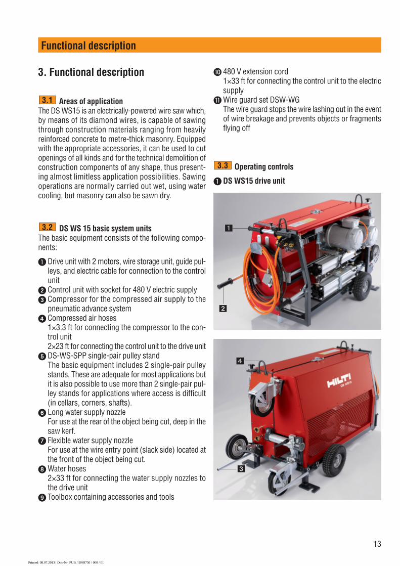
� Drive unit with 2 motors, wire storage unit, guide pul-leys, and electric cable for connection to the controlunit
Control unit with socket for 480 V electric supply � Compressor for the compressed air supply to the
pneumatic advance system � Compressed air hoses
1×3.3 ft for connecting the compressor to the con-trol unit2×23 ft for connecting the control unit to the drive unit
� DS-WS-SPP single-pair pulley standThe basic equipment includes 2 single-pair pulleystands. These are adequate for most applications butit is also possible to use more than 2 single-pair pul-ley stands for applications where access is difficult(in cellars, corners, shafts).
� Long water supply nozzleFor use at the rear of the object being cut, deep in thesaw kerf.
� Flexible water supply nozzleFor use at the wire entry point (slack side) located atthe front of the object being cut.
Water hoses2×33 ft for connecting the water supply nozzles tothe drive unit
Toolbox containing accessories and tools
3.1
3.2
Functional description
Operating controls
� DS WS15 drive unit
3.3
�
�
�
�
� 480 V extension cord1×33 ft for connecting the control unit to the electricsupply
� Wire guard set DSW-WGThe wire guard stops the wire lashing out in the eventof wire breakage and prevents objects or fragmentsflying off
Printed: 08.07.2013 | Doc-Nr: PUB / 5069750 / 000 / 01

14
Functional description
� T–shaped transportation handle, pull-out type � Folding transportation handle � Transportation or lifting lever for raising the wheels� Lifting points for transportation by crane
� Cable and hose storage compartment� Electric cables for drive motors � Electric cable for control system
2 compressed air connections for advance pressurecylinder
1 water connection, water supply from construction site
�� 2 water connections for cooling water supply to thediamond wire
� 2 baseplates for securing the drive unit to the flooror ground
�� Three-point supports, adjustable in height
12
�
�
�
��
�
Printed: 08.07.2013 | Doc-Nr: PUB / 5069750 / 000 / 01

15
Functional description
�� Tension-side guide pulley, adjustable in direction andposition
�� Diamond wire lead-in guide�� Slack-side guide pulley – adjustable in direction�� Cylindrical socket for vertical sawing device or for
grip bar
� Wire clamping vice
�� Compressed air cylinder stop piece
�� Side cover
�� Drive wheel 1, 280 mm dia., fixed�� Drive wheel 2, 280 mm dia., moving�� Storage pulleys, 280 mm dia., moving�� Storage pulleys, 200 mm dia., fixed
21
22
����
��
��
��
��
����
��
Printed: 08.07.2013 | Doc-Nr: PUB / 5069750 / 000 / 01
16
Functional description
Operating controls
Control unit DS EB-WS15
3.3.1
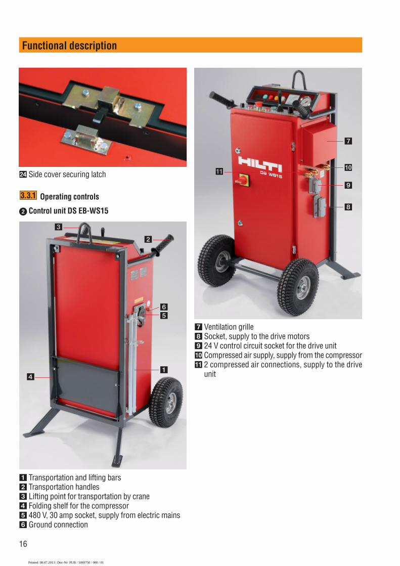
� Transportation and lifting bars� Transportation handles� Lifting point for transportation by crane� Folding shelf for the compressor� 480 V, 30 amp socket, supply from electric mains� Ground connection
� Ventilation grille Socket, supply to the drive motors 24 V control circuit socket for the drive unit�� Compressed air supply, supply from the compressor � 2 compressed air connections, supply to the drive
unit
�� Side cover securing latch
�
�
�
��
�
�
�
��
Printed: 08.07.2013 | Doc-Nr: PUB / 5069750 / 000 / 01
17
Functional description
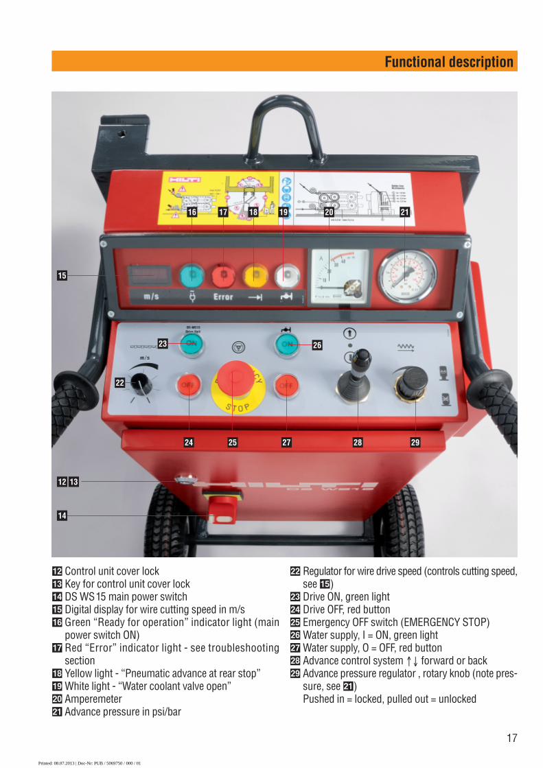
�� Control unit cover lock�� Key for control unit cover lock�� DS WS15 main power switch�� Digital display for wire cutting speed in m/s�� Green “Ready for operation” indicator light (main
power switch ON)�� Red “Error” indicator light - see troubleshooting
section �� Yellow light - “Pneumatic advance at rear stop”�� White light - “Water coolant valve open”�� Amperemeter� Advance pressure in psi/bar
�� Regulator for wire drive speed (controls cutting speed,see ��)
�� Drive ON, green light�� Drive OFF, red button�� Emergency OFF switch (EMERGENCY STOP)�� Water supply, I = ON, green light�� Water supply, O = OFF, red button�� Advance control system ↑↓ forward or back�� Advance pressure regulator , rotary knob (note pres-
sure, see � )Pushed in = locked, pulled out = unlocked
16
15
17 18 19 20 21
22
23 26
14
12 13
24 25 27 28 29
Printed: 08.07.2013 | Doc-Nr: PUB / 5069750 / 000 / 01
18
Functional description
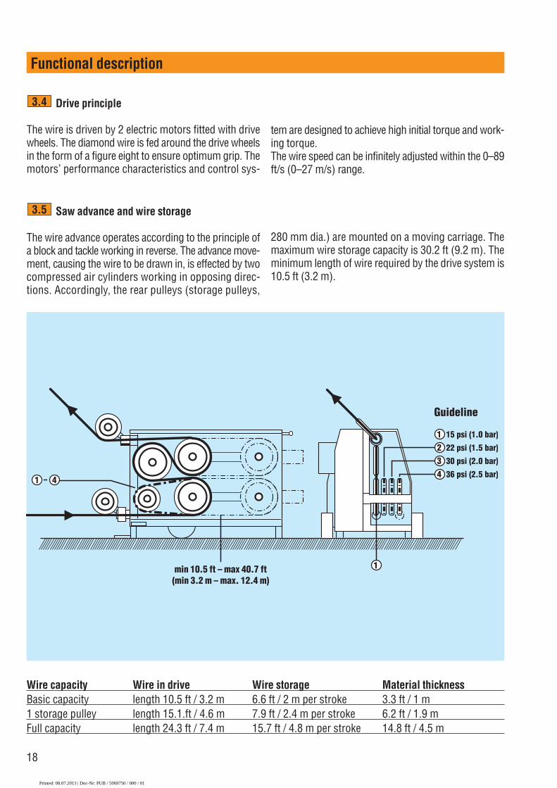
Drive principle
The wire is driven by 2 electric motors fitted with drivewheels. The diamond wire is fed around the drive wheelsin the form of a figure eight to ensure optimum grip. Themotors’ performance characteristics and control sys-
3.4
Saw advance and wire storage
The wire advance operates according to the principle ofa block and tackle working in reverse. The advance move-ment, causing the wire to be drawn in, is effected by twocompressed air cylinders working in opposing direc-tions. Accordingly, the rear pulleys (storage pulleys,
3.5
1 4
min 10.5 ft – max 40.7 ft(min 3.2 m – max. 12.4 m)
1234
15 psi (1.0 bar)
22 psi (1.5 bar)
30 psi (2.0 bar)
36 psi (2.5 bar)
1
Guideline
tem are designed to achieve high initial torque and work-ing torque.The wire speed can be infinitely adjusted within the 0–89ft/s (0–27 m/s) range.
280 mm dia.) are mounted on a moving carriage. Themaximum wire storage capacity is 30.2 ft (9.2 m). Theminimum length of wire required by the drive system is10.5 ft (3.2 m).
Wire capacity Wire in drive Wire storage Material thicknessBasic capacity length 10.5 ft / 3.2 m 6.6 ft / 2 m per stroke 3.3 ft / 1 m1 storage pulley length 15.1.ft / 4.6 m 7.9 ft / 2.4 m per stroke 6.2 ft / 1.9 mFull capacity length 24.3 ft / 7.4 m 15.7 ft / 4.8 m per stroke 14.8 ft / 4.5 m
Printed: 08.07.2013 | Doc-Nr: PUB / 5069750 / 000 / 01

19
Functional description
Wire guidance
Guide pulleys are fitted on the wire tension side and onthe return side (slack side). The wire is guided to theobject being sawn by way of these guide pulleys whichcan be adjusted in any direction. Wire guides in the formof single-stands, plunge pulleys etc., are mounted at thestart and end of the cut. The wire is thus guided and cutsa controlled arc. The wire guides, pulleys and support-ing steel tube prevent the wire jumping off uncontrol-lably at the end of the cut and act as a safety device oras a wire trap in the event of the wire breaking.
Optimum wire guidance is one of the most importantand demanding tasks in wire sawing. The distribution ofthe cut and the arrangement of the pulley stands con-trol the length and curvature of the arc cut by the wire,thus influencing both the service life of the wire as wellas the rate of cutting progress.
3.6
Printed: 08.07.2013 | Doc-Nr: PUB / 5069750 / 000 / 01
20
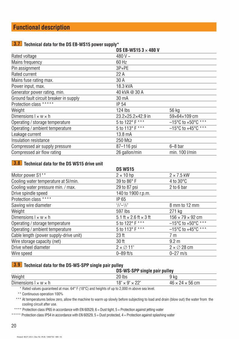
Technical data for the DS EB-WS15 power supply*DS EB-WS15 3 × 480 V
Rated voltage 480 V ~ Mains frequency 60 HzPin assignment 3P+PERated current 22 AMains fuse rating max. 30 APower input, max. 18.3 kVAGenerator power rating, min. 40 kVA @ 30 AGround fault circuit breaker in supply 30 mAProtection class ***** IP 54Weight 124 lbs 56 kgDimensions l × w × h 23.2×25.2×42.9 in 59×64×109 cmOperating / storage temperature 5 to 122° F *** –15°C to +50°C ***Operating / ambient temperature 5 to 113° F *** –15°C to +45°C ***Leakage current 13.8 mAInsulation resistance 250 MΩCompressed air supply pressure 87–116 psi 6–8 barCompressed air flow rating 26 gallon/min min. 100 l/min
Technical data for the DS WS15 drive unitDS WS15
Motor power S1** 2 × 10 hp 2 × 7.5 kWCooling water temperature at 5l/min. 39 to 86° F 4 to 30°CCooling water pressure min. / max. 29 to 87 psi 2 to 6 barDrive spindle speed 140 to 1900 r.p.m.Protection class **** IP 65Sawing wire diameter 1/3"–1/2" 8 mm to 12 mmWeight 597 lbs 271 kgDimensions l × w × h 5.1 ft × 2.6 ft × 3 ft 156 × 79 × 92 cmOperating / storage temperature 5 to 122° F *** –15°C to +50°C ***Operating / ambient temperature 5 to 113° F *** –15°C to +45°C ***Cable length (power supply-drive unit) 23 ft 7 mWire storage capacity (net) 30 ft 9.2 mDrive wheel diameter 2 × ∅ 11" 2 × ∅ 28 cmWire speed 0–89 ft/s 0–27 m/s
Technical data for the DS-WS-SPP single pair pulleyDS-WS-SPP single pair pulley
Weight 20 lbs 9 kgDimensions l × w × h 18" × 9" × 22" 46 × 24 × 56 cm** ** Rated values guaranteed at max. 64° F (18°C) and heights of up to 2,000 m above sea level. * * ** Continuous operation 100%* *** At temperatures below zero, allow the machine to warm up slowly before subjecting to load and drain (blow out) the water from the
cooling circuit after use.* **** Protection class IP65 in accordance with EN 60529, 6 = Dust tight, 5 = Protection against jetting water***** Protection class IP54 in accordance with EN 60529, 5 = Dust protected, 4 = Protection against splashing water
3.9
3.8
3.7
Functional description
Printed: 08.07.2013 | Doc-Nr: PUB / 5069750 / 000 / 01

21
Functional description
Type plates3.10
� �
�
�
� = Engineering number� = Spare parts list index� = Serial number� = Year of manufacture
� �
�
�
��
�
�
Printed: 08.07.2013 | Doc-Nr: PUB / 5069750 / 000 / 01

22
Electric power supply / fuse rating
-CAUTION-Irrespective of whether using mains power or genera-tor power, always check that an earth/ground conduc-tor and ground fault circuit breaker are present in the
4.3
Assembly
4. Assembly
Planning the wire guidance system
■ Before installing the wire saw, you must carefullystudy the situation and plan the wire guides, the drillingof through-holes, the sequence of the work and theprocedure involved. You must also plan the coolingwater supply and, if necessary, waste water –disposal.
■ Consideration must be given to safety aspects andcordoning off to prevent access by third parties etc.
■ Secure the area, plan the removal and transportationof the sawn-out sections of the structure and all oth-er necessary measures.
Positioning the wire guide pulleys
4.1
4.1.1
αH
L
Rule of thumb : Pulley clearance H= 0.2 m per metre sawing length L
�Sawing length L:
1,10�
1,00�
0,90�
0,80�
0,70�
0,60�
0,50�
0,40�
0,30�
0,20�
0,10�
0,00� Pul
ley
clea
ranc
e H
(met
re)
Angle of obliquity of action α (α )
0
1 metre 2 metre 3 metre 4 metre
5 10 15 20 25 30
Wire pressure4.1.2
90 85 80 75 70 65 60 55 50 45 40 35 30 25 20 15 10 5 0
Angle of obliquity of action α (α )
70 �
60 �
50 �
40�
30�
20�
10�
0
Co
ntac
t p
ress
ure
forc
e o
f th
e w
ire�
(N) x
10
α0�=90αα
α1�=70αα
α2�=20αα
αe=0αα
F
F
F
F
Drilling through-holes for the wire
■ According to the situation, the material to be cut andthe amount of reinforcement in the concrete, a ham-mer drill and long drill bits or a diamond coring machinemounted on a stand can be used to drill through-holes. Depending on the thickness of the section tobe cut and the material involved, we recommend drillbits of 5/8", (16 mm), 11/2", (37 mm), 25/8", (67 mm) or4", (102 mm) diameter.
■ Depending on the application, you will also requireaccessories and special solutions for drilling to greaterdepths.
4.2
Printed: 08.07.2013 | Doc-Nr: PUB / 5069750 / 000 / 01
23
Assembly
power supply and that these are connected. If in doubtabout a correct earth/ground connection in the powersupply, the Control Unit must be grounded with theground connection provided on the Control Unit. Thefuse rating of the electric power supply at the construc-tion site must be as follows:
Voltage version 3 × 480 VMaximum fuse rating 30 AGround fault circuit breaker (FI) Type A 30 mA
Electric power connection / power cable plugs
Voltage version 3 × 480 VPin assignment 3 Pole, 4 Wire
Grounding (3P+PE)Pinassignment
X = phase 1, Y = phase 2, Z = phase 3, G = earth / ground (PE)
The power supply cable supplied with the tool has to beused to connect the tool to the local power supply.
Extension cables / conductor cross section
■ Use only extension cables which are approved for theintended field of use and with conductors of adequatecross section.
■ For extension cables use following cable specifica-tion and minimum conductor cross sections: cableextra hard type for wet and outdoor locations, 4 wiresAWG10, 3P+PE, 480 V / 30 A (conductor cross sec-tion = cross-sectional area of individual conductors).
■ Inadequate conductor cross sections and long cablesresult in a drop in voltage and may cause the cable tooverheat.
Transporting the wire saw
■ The wheels on the DS WS15 drive unit must be fold-ed up before it is transported in your vehicle or on atrailer. The drive unit, control unit and other compo-nents must be secured with suitable belts to preventthem moving around or falling over.
4.5
30A 3Ø 480V ACNEMA L16-30P
UL/CSA10 HP
X
Z
Y G
4.4
4.6
1
2
■ Use suitable lifting gear or non-slip, stable ramps to load/ unload the equipment into the vehicle or onto the trailer.
■ The DS WS15 control unit can be moved without anyproblem by means of the 2 hand grips. A lifting pointis provided for the purpose of transportation by crane.
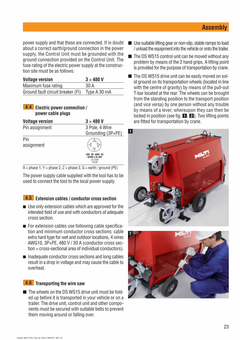
■ The DS WS15 drive unit can be easily moved on sol-id ground on its transportation wheels (located in linewith the centre of gravity) by means of the pull-outT-bar located at the rear. The wheels can be broughtfrom the standing position to the transport position(and vice versa) by one person without any troubleby means of a lever, whereupon they can then belocked in position (see fig. �, �). Two lifting pointsare fitted for transportation by crane.
Printed: 08.07.2013 | Doc-Nr: PUB / 5069750 / 000 / 01

24
��
��
Assembly
Securing the wire guides and saw drive unit
■ To ensure efficient and safe operation it is essentialthat the saw and the pulley stands are fastened cor-rectly and securely using fasteners of adequate size.WARNINGUse an anchor suitable for the material on which youare working and observe the anchor manufacturer’sinstructions.NOTEHilti HDI 1/2" metal expansion anchors are usually sui-table for fastening diamond core drilling equipmentto uncracked concrete. Under certain conditions itmay be necessary to use an alternative fasteningmethod. Please contact Hilti Technical Service if youhave any questions about secure fastening.
■ Your Hilti representative will be pleased to provideadvice in case of questions concerning fastening secu-rity on base materials such as brittle or cracked con-crete, masonry and synthetic or natural stone.
■ The clamping spindles and clamping nuts with swiv-el baseplate recommended for use with these anchorsensure that the equipment can be fastened in positionquickly and securely. Important: The clamping spin-dles are wearing parts and should be replaced whennecessary. Check that they are in good condition beforeuse and do not straighten them by hammering.
■ Alternatively, ceiling support jacks, quick-releasecolumns or tension belts may be used instead ofanchors for securing the DS WS15 drive unit.
■ The anchors for fastening the single-pair pulley stands
4.7
� Clamping nut with swivelling baseplate � Clamping spindle with double-start thread� Through-hole for the diamond wire� Levelling screw
do not require to be very precisely positioned. Thanksto their adaptable clamping system, the pulley standsand guide pulleys can always be lined up precisely withthe cut. Approximate positioning is adequate (see fig).
■ In addition to the central clamping spindle, the level-ling screws on the pulley stands can also be tight-ened. The wire guide pulleys are then fastened secure-ly and will not work loose, even when subjected tovibration.
Connecting the electric power, water andcompressed air
Please also refer to Section 2, “Description of the sawsystem”■ Situation: The wire saw is installed, all switches at
the control unit are in the OFF or NEUTRAL posi-tions, the EMERGENCY STOP button is pressed in.
■ Connect the system’s own power cable and controlcable between the drive and the control unit. Important:The control unit must be positioned outside the haz-ardous area of wire saw operation!
■ Connect the socket of the mains supply cable / exten-sion cable to the control unit.
■ Install the water supply with a feed of at least 1.3gal/min at a max. water pressure of 87 psi for the DSWS15 drive, and connect it to the rear of the driveunit by way of the quick-release couplings.
■ Lead 2 cooling water hoses from the front of the driveunit (close to the guide pulleys), by way of the quick-release water couplings, to the cutting face where saw-ing is taking place and connect them to the flexible watersupply nozzle and to the long water supply nozzle.
■ Turn the main switch at the control unit to ON. The indi-cator lamp lights up green and the outflow water valveat the drive unit closes automatically. Note: The redERROR warning lamp may possibly light up for approx-imately 6 seconds, until the correct tension is reached.
■ Connect the compressor to the mains supply andswitch it on immediately. As soon as the compressorswitches off automatically, i.e. when the pressure tankis full, connect the compressed air hose of the com-pressor and the control unit (one hose), and then con-nect the control unit to the drive by means of the 2long compressed air hoses. The compressor restartsautomatically, when necessary.
■ Open the tap at the jobsite water supply. The water
4.8
Printed: 08.07.2013 | Doc-Nr: PUB / 5069750 / 000 / 01

25
Assembly
does not yet flow through the machine to the waternozzles (water flows only when the cooling water isswitched on at the control unit).
■ The DS WS15 drive unit has to be cooled even whenused for dry cutting applications (the diamond wiremay not have to be cooled when cutting brickwork).As an alternative to connection to a fresh water sup-ply, cooling can be achieved by means of a submersiblepump in a water reservoir. The cooling water can bereturned to this reservoir from one of the two watertaps located at the front of the drive unit, thus form-ing a closed circuit system.
■ Insufficient cooling water or a water temperature sig-nificantly in excess of 68°F can lead to premature acti-vation of the temperature protection control switch. Themotors then switch off automatically and the "Error”warning lamp lights (see also "Error messages” section).
Rigging and tensioning the wire
■ Situation: The length of the wire and the optimumposition of the drive has been fixed. The drive unithas been set up at approximately the correct distanceto the structure to be cut. The wire has been fittedwith wire connectors.
■ Important: When the wire is threaded through, atten-tion must be paid to correct direction of travel.The forked piece of the wire connector must corre-spond to the directional arrow on the wire. Should thearrow on the wire no longer be visible, the direction oftravel can be determined from the diamond beads. Thebeads are slightly conical in the direction of travel (nar-row end ahead) and the diamonds can be seen to havea “tail” that trails behind.
■ The wire running in the direction of tension from theobject being cut is always fed to the drive unit via thelower guide pulley or, respectively, through the lowerhollow axle. Important: Always use the shorter free wirelength as the tension side! The system will then workmore efficiently, more safely and with reduced wire wear.
■ Feed the wire from the hollow axle of the lower guidepulley of the drive � at the tension side through thepulley guide mounted at the closer through-hole �
4.9
and then through the hole to the rear of the objectbeing cut. From there, the wire should return via thenext previously-drilled through-hole � to the nextpulley guide from where it is then fed back to the slackside (wire return side) of the drive unit �.
12
3
4
■ Important: We recommend that the following proce-dure is followed now, at the latest, before the two endsof the wire are connected: The operators should pullthe wire through by hand, in both directions alter-nately in a “sawing” motion, so that the wire alreadybegins to cut slightly into the object to be sawn. Thisprocedure ensures that the wire guides are securedcorrectly in position at the object to be cut and thatthe wire is free to move when sawing begins.
■ To ensure that the wire wears evenly and stays round,we recommend that the wire is twisted in a counter-clockwise direction (approx. 0,2 turns per ft length)before the ends are connected together.
Printed: 08.07.2013 | Doc-Nr: PUB / 5069750 / 000 / 01

26
Assembly
■ Starting from the upper guide pulley (hollow axle) locat-ed at the slack side, pass the connected wire aroundthe 280 mm diameter drive wheels (refer to the stick-er on drive unit) and fix the lower guide pulley on thetension side in the corresponding storage position.Pass the wire around the storage pulleys in one or moreturns, as necessary. When doing so, it may be neces-sary to re-position the entire drive unit by moving itforward or back before fastening it in position.
■ Ideally, the drive should be rigged with only the basicminimum length of wire 10.5 ft (3.2 m) at the com-mencement of sawing. This allows the maximum thick-ness to be sawn through without having to adjust orchange the wire. Nevertheless, it is possible to beginsawing with the wire storage pulleys occupied to full capacity.
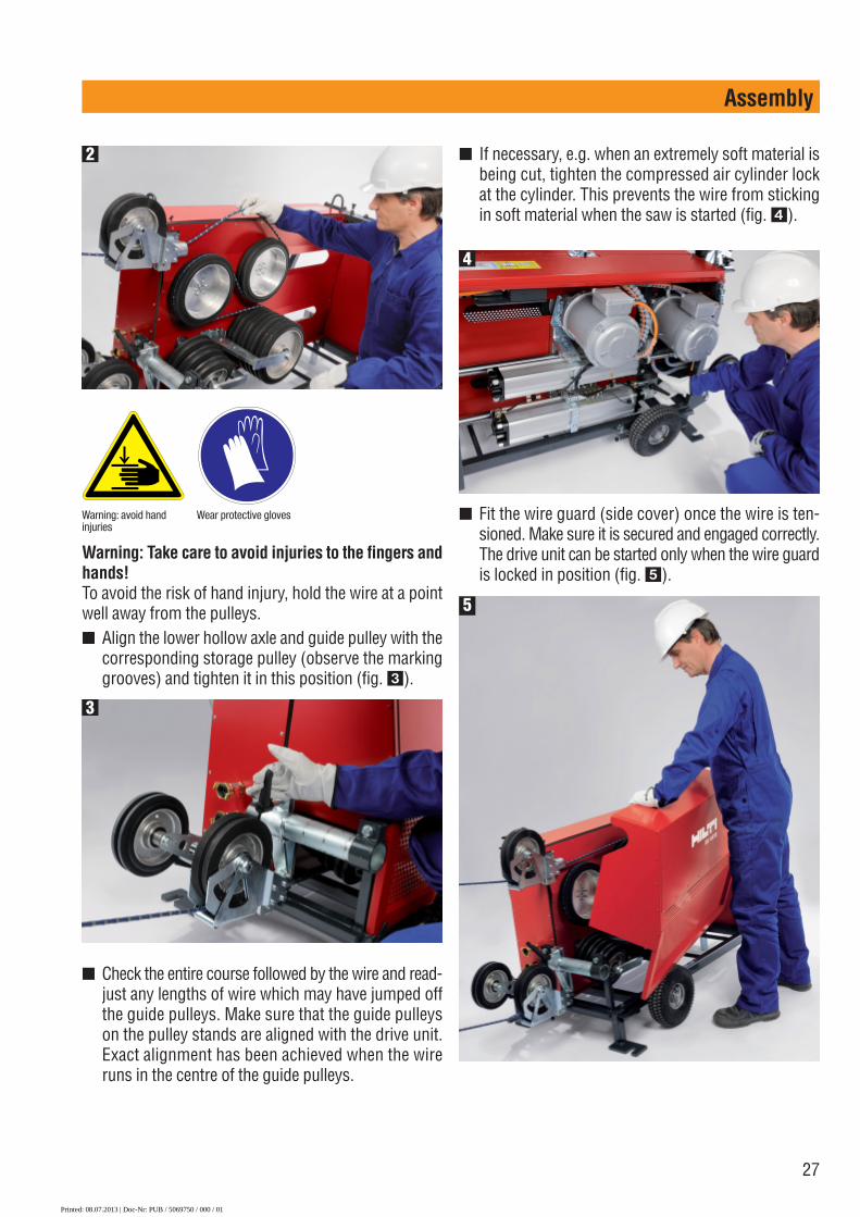
■ The operator at the control unit should set the advancepressure to approximately 14.2 psi (1 bar) by adjust-ing the pressure control and then tension the wire bymoving the advance lever (fig. �). At the same time,the operator at the drive unit should ensure that thewire is lying correctly on the storage pulleys (fig. �).
1
■ Move the drive motor on the carriage manually intothe desired position. Before this can be done, the twocompressed air connections located at the rear of thedrive must be connected, or coupled together (so thatthe air in the pressure cylinders can circulate).
Printed: 08.07.2013 | Doc-Nr: PUB / 5069750 / 000 / 01
27
Assembly
Warning: Take care to avoid injuries to the fingers andhands! To avoid the risk of hand injury, hold the wire at a pointwell away from the pulleys.■ Align the lower hollow axle and guide pulley with the
corresponding storage pulley (observe the markinggrooves) and tighten it in this position (fig. �).
■ If necessary, e.g. when an extremely soft material isbeing cut, tighten the compressed air cylinder lockat the cylinder. This prevents the wire from stickingin soft material when the saw is started (fig. �).
■ Fit the wire guard (side cover) once the wire is ten-sioned. Make sure it is secured and engaged correctly.The drive unit can be started only when the wire guardis locked in position (fig. �).
Warning: avoid handinjuries
Wear protective gloves
3
2
4
5
■ Check the entire course followed by the wire and read-just any lengths of wire which may have jumped offthe guide pulleys. Make sure that the guide pulleyson the pulley stands are aligned with the drive unit.Exact alignment has been achieved when the wireruns in the centre of the guide pulleys.
Printed: 08.07.2013 | Doc-Nr: PUB / 5069750 / 000 / 01

28
Setting up the wire cooling system
■ Ideally, hoses should beled from the 2 water con-nections with valves atthe front of the controlunit to the flexible watersupply nozzle at the pointwhere the wire enters thefront side of the objectbeing cut and to the sec-ond (long) water supply nozzle positioned at the dia-mond wire on the rear side of the object. The watersupply nozzles can be mounted by pushing the wedgeinto the kerf or temporarily by some other suitablemeans.
■ When dry cutting, the water outlet from the drive unitis fed into the drainage system or a reservoir and notto the saw kerf.
■ The cooling water supply is controlled by the ON andOFF buttons on the control unit.
■ If less water than required for cooling the drive unit isused for cooling the wire, a proportion of the watercan be fed directly into the drainage system by way ofthe second valve located at the front of the drive unit.
4.10
Assembly
Water connection to drive unit
Water supply to the cut
Control unit – water on / off
Basic applications
Standard vertical cut■ Illustration: Using a single-pair pulley stand
(DS-WS-SPP)■ Optimum length of cut■ Avoid a tight radius in the concrete■ Good cutting performance (cutting speed)■ Normal rate of wire wear
4.11.1
4.11
Vertical cut with DS-WSRW release pulley
1st step■ Illustration: Using a double-pair pulley stand
(made up from two DS-WS-SPP)■ Relatively short length of cut■ High cutting performance (cutting speed)■ Slightly higher rate of wire wear■ Note: Once the kerf reaches the height of the pulley
�, rotate the pulley so that it points downwards.
4.11.2
Water
Wat
er
Diamond wiretension side
Water
Wat
erRe
leas
e pu
lley
Diamond wiretension side
�
Printed: 08.07.2013 | Doc-Nr: PUB / 5069750 / 000 / 01

29
Assembly
2nd step■ Disengage the wire from the release pulley when the
cut is approx. 50% complete, i.e. the wire then alsobegins to cut from below.
■ Provided the operator remains outside the dangerzone, this can be done while sawing continues bymeans of a long string: simply pull out the bolt fromthe release pulley!
1
D
2
Water
Rele
ase
pulle
y
■ The wire is caught by pulleys � and when itescapes from the kerf at the end of the cut.
Example: Using a double-pair pulley stand for avertical cut through a concrete component
Distance “D” between the drive and objectbeing cut
■ The distance “D” between the drive unit and the objectbeing cut is determined by the application. The idealdistance, i.e. the “free wire length”, is approximate-ly 6–10 ft. For even greater distances, the wire mustrun over an additional pulley stand. The distance “D”(or "free wire length”) should always be kept as shortas possible for safety reasons.
4.11.3
Optimum length of cut “L”■ The optimum length of cut “L”, i.e. the wire length
effectively involved in cutting process, ranges fromapproximately 6–26 ft for the DS WS15 wire saw.This enables the operator to achieve the greatest effi-ciency, and also ensures good service life of the wire.
Standard horizontal cut■ Position the drive unit at a short distance from the
object to be cut, with the tension side facing the object.■ Position the control unit outside the danger zone.
4.11.4
4.11.5
Printed: 08.07.2013 | Doc-Nr: PUB / 5069750 / 000 / 01

30
Assembly
Pivoting pulley with ball bearing at pivot point
Pivoting pulleywith ball bear-
ing at pivotpoint
Diamond wire
Clampingscrew
Ball bearing
Pivotingpulley
Cuttingplane
Friction bearingCan be locked bytightening screw
Clamping screwRelease screw for
flush cutting
Using plunge pulleys■ A plunge cutting application in a solid material is
described. ■ For a cut of 6–10 ft in length, the plunge pulleys must
be set approximately 8"–12" deeper because the endof the cut always takes the form of an arc.
4.11.7
■ Guide pulley tube attached directly to the baseplate
■ Guide pulley tube attached to the distance piece
20–30 cm
∅ 162 mm
Flush horizontal cut■ The pulley stand should be mounted so that the piv-
oting guide pulley (on bearings), with the clampingscrew at the rear, is almost in contact with the sur-face along which the flush cut is to be made. Thereshould be a maximum of about 1/4" play between theflush surface and the guide pulley.
■ The pivoting guide pulleys should be positioned fac-ing outwards at the beginning of the cut and shouldbe free to pivot.
■ At the end of the cut, the pulleys will have pivoted toface inwards as they follow the course of the wire.
4.11.6
Printed: 08.07.2013 | Doc-Nr: PUB / 5069750 / 000 / 01

31
Assembly
■ In so-called "external plunge” applications, the plungepulleys are mounted on the outside of the object beingcut. Cross-type tube clamps are used to mount theplunge pulleys on single-pair pulley stands. The time-consuming job of drilling through the object to be cutis thus no longer necessary.
Using the DS-WSVC vertical cutting device■ No pulley stands are required for this type of cut.■ The drive unit is positioned directly on the object to
be cut.■ Care must be taken to ensure that the drive unit and
the guides for the wire to the object being cut are atright angles to each other. This can be adjusted bymeans of the height adjustment mechanism at therear.
4.11.8
Assembly instructions DSW-WG Protectivecover
■ Use the protective cover to augment the safety onyour jobsite. NEVER enter the danger area while saw-ing is in progress.
■ Mount the cover according to the assembly instruc-tions below. It can be mounted after complete set upof the wire saw.
4.11.9
1
2
3
Printed: 08.07.2013 | Doc-Nr: PUB / 5069750 / 000 / 01

32
Operation
5. Operation
Checks prior to beginning sawing
■ On-site preparatory work should be completed (sup-ports, cordoning off the danger zone, arrangementsfor water collection etc.)
■ The pulley stands and the drive unit should be cor-rectly secured and the wire rigged on the saw in thecorrect direction of travel, the wire guards fitted, wireguidance on the pulleys checked and the guide pul-leys tightened. The cooling water supply to the wireshould have been installed.
■ Electric power, compressed air and water should beconnected. The power supply should be equippedwith an earth/ground conductor and ground fault cir-cuit breaker (PRCD) and should have been checked/ tested. Water and compressed air supplies shouldbe within the permitted pressure range.
■ The control unit should be located outside the dan-ger zone, hazardous areas in front of and behind theobject to be sawn should have been checked and cor-doned off and no persons should be present in thehazardous area.
The starting procedure
■ Situation: The main switch is in the ON position. The“power” indicator light is green. The compressor andthe system are pressurised. The advance lever is inthe “sawing” (advance) position. The remaining switch-es are OFF or set at “0”.
■ If necessary, when cutting masonry, the lower advancecompressed air cylinder may be locked in positionusing the locking ring provided.
■ Open the 2 water valves on the drive unit for the watersupply to the cutting face.
■ Adjust the advance pressure to approximately 1 barat the control unit by means of the control knob (pulledout), or to the pressure recommended depending onthe wire used for sawing.
■ Switch on the water supply. The white indicator lamplights.
■ Switch on the drive (green “DS WS15 Drive Unit”push-button).
5.1
5.2
■ Use the speed regulator to increase speed graduallyand, once the wire is running at a low speed (approx-imately 3–10 m/s cutting speed), allow the wire tocut for a few seconds. Check that the wire is runningcorrectly on all guide pulleys (max. 1 minute).
■ By adjusting the speed regulator, accelerate the motorsuntil the wire is running at the desired or, respectively,the optimum cutting speed.
Recommended cutting speeds (approximate)Cutting Recommended Recommendedmethod cutting speed wire lengthWet Approx. 20–25 m/s Keep wire as short as possible Dry Approx. 10–20 m/s Long wire (assists cooling)
■ Set the advance pressure (bar) so that current con-sumption is 25 – 30 amps.
■ The DS WS15 now continues sawing automatically.Monitor the cutting process. Normally, the saw hasto be stopped for a short time soon after beginningcutting. Stop the saw by switching the drive OFF andthen press in the EMERGENCY STOP button. Checkthe wire guidance and readjust the water supply.
■ If necessary, release the locking ring on the com-pressed air cylinder.
The sawing operation
■ Release the EMERGENCY STOP button and start thedrive (the speed and pressure are already set andremain unchanged). The motors accelerate up tospeed. The wire saw then cuts automatically.
■ Monitor the sawing operation, paying particular atten-tion to the cooling water supply to the wire. Whenwet sawing, the cooling water system must be read-justed as soon as dust is produced. In most cases,alignment of the guide pulleys also has to be changedapproximately half-way through the cut.
Wire cooling Cutting method Cooling CommentsWet Approx. 5 litres of NO dust should be produced.
water per min. Readjust water supply.Dry “Air cooling” - If necessary, use vacuum
long wire cleaner to remove dust at the wire exit point.
■ The yellow warning lamp ➜I lights and the machineswitches off. The drive carriage has reached the end ofits travel, i. e. is at the advance end stop. Press the dri-
5.3
Printed: 08.07.2013 | Doc-Nr: PUB / 5069750 / 000 / 01

33
Operation
ve OFF and the EMERGENCY STOP buttons. Stop theflow of cooling water.
■ Remove the cover from the drive unit and bring thetravelling drive motor into the forward drive positioneither manually or using the compressed air control system.
■ Wind the slack wire onto the storage pulleys. The sec-ond operator ensures that the wire is correctly posi-tioned on the pulleys. Re-adjust the hollow axle of theguide pulleys at the tension side to bring it into align-ment with the wire entering the store and tighten theclamping screw. Replace the wire compartment cov-er.
■ Should the wire store offer insufficient capacity dur-ing extreme applications, simply move the drive unitback a distance of 3–6 ft and then re-secure it in itsnew position.
■ Check the alignment of the guide pulleys and read-just if necessary.
■ Reset the advance pressure to the recommended val-ue in accordance with the table. Lock the compressedair control knob again and switch on the cooling watersystem.
■ Disengage the EMERGENCY STOP button and pressthe drive ON button. Use the speed control knob toaccelerate gently to the desired or optimum cuttingspeed. The DS WS15 then saws automatically.
■ Monitor the sawing operation. If the saw wire vibratesexcessively, check the alignment of the pivoting orguiding pulleys. If necessary, adjust the wire speedand advance pressure slightly.
■ Important: Press the EMERGENCY STOP button inthe event of a critical or dangerous, unforeseen situ-ation developing while sawing, e.g. a wire jumpingoff a guide pulley or a person entering the danger areaunexpectedly. The drive unit then switches off.
■ Closely observe sawing progress and pay attentionto the guide pulleys. Switch off the machine and piv-ot the guide pulleys through 180° in good time - beforethe wire begins to cut into the hollow axle betweenthe pulleys!
■ Adequate cooling water and round, gentle cutting arcsare the decisive factors in achieving good cuttingresults in terms of cutting speed, safety and wire life.
■ The drive unit must be switched off and the EMER-GENCY STOP button pressed before readjusting thewater supply, swivelling the guide pulleys, wind-ing wire onto the storage pulleys and before clean-ing parts.
■ When switching the drive unit off temporarily (e.g.when adjusting the water supply etc.) do not alter thepreviously set parameters such as drive speed andadvance pressure (compressed air set at 1.5 bar, forexample). These operating controls can remain at theprevious settings.
Ending the sawing operation
■ Towards the end of the cut, the arc followed by thewire becomes increasingly flat, sawing efficiencydrops and the tension on the wire increases. If nec-essary, the guide pulleys can then be mounted at theend of the pulley stand, further away from the objectbeing cut.
■ Prior to completing the cut and sawing right through,ensure that the part of the object being cut (or beingcut free) is secured so that it cannot move or will movein the desired direction. If necessary, use steel wedgesto secure the object temporarily.
■ Reduce the speed of the wire considerably during thefinal cutting phase. In normal circumstances, the wirewill be caught by the guide pulleys, without jumpingoff. Switch off the drive unit after the object has beensawn through.
■ Set all operating controls on the control unit to theOFF or neutral positions and press the EMERGENCYSTOP button. The main power switch may be left inthe ON position and the electric supply cable shouldremain connected.
■ Immediately after completing the cut, wash down thepulley stands and the guide pulleys mounted at theobject cut and on the drive unit by spraying the partswith water, paying special attention to the guide pul-leys and wire storage section.
5.4
Printed: 08.07.2013 | Doc-Nr: PUB / 5069750 / 000 / 01

34
Maintenance
6. Maintenance
Cleaning the wire saw
CAUTIONDisconnect the supply cord plug from the power outlet.
CAUTIONKeep the machine, especially its grip surfaces, clean andfree from oil and grease. Do not use cleaning agentswhich contain silicone.
■ We recommend that the most important parts of thewire saw are cleaned quickly between each cut made.Simply hose down the guide pulleys, the pulley standsand the front as well as the wire storage section ofthe drive unit.
■ All operating controls should be switched to the OFFor neutral position prior to more thorough daily clean-ing of the equipment. Switch off the main switch atthe control unit and disconnect the power supply plug.
■ Wash down the complete set of equipment at the endof each working day using a hose and brush, payingspecial attention to the parts mentioned above. Thecleaning operation should be part of your daily workschedule and ensures that you will be able to workefficiently each day. If the equipment is left uncleanedeven for only one night, the guide pulleys and mov-ing parts will become stuck with hardened concreteslurry which will then have to be removed in a tedious,time-consuming process, with a risk of causing dam-age to the parts.
■ Do not hose down the control unit, simply wipe itclean with a damp cloth. Use of a high-pressure steamcleaning system is not permissible!
■ After cleaning the equipment, check the guide pul-leys and moving parts for ease of movement. Inspectthe parts to ensure they are in good condition and thecontrols are in good working order. Damaged or mal-functioning parts must be replaced immediately inorder to avoid accidents or further costly damage.
■ At temperatures below zero (-°C), the cooling watermust be blown out of the motors after work or clean-ing is complete (open one of the two water taps atthe front and direct compressed air into the drive �unit water supply connector �). Blow through untilall water is forced out.
6.121
Printed: 08.07.2013 | Doc-Nr: PUB / 5069750 / 000 / 01

35
Maintenance
Wearing parts
■ A list of the most important consumables and wear-ing parts is provided in Section 7 and in the tools /accessories brochure. Please contact your Hilti rep-resentative if you require parts.
Service and repair
■ Malfunctions are unlikely to occur as long as the equip-ment is kept clean and well lubricated. Dirty parts andincorrect operation lead to malfunctions.
■ The mechanical design of the wire saw system hasbeen kept very simple. With the aid of the consum-ables items and wearing parts supplied by Hilti, theoperator is in a position to maintain and service themechanical parts of the system himself by replacingitems such as guide pulleys or connectors etc.
■ Other parts (spare parts) are available as necessaryfrom the service department and can usually be fit-ted on-site by the operator himself or by a Hilti dia-mond systems specialist or Hilti mechanic.
■ It may happen, for various reasons, that one of thefuses in the control unit blows.
■ All fuses are available commercially and a spare setof fuses is provided inside the control unit. The fus-es in the control unit can be replaced by the opera-tor. Please refer to the “Accessories” and “Fault Find-ing” sections.
■ Repairs or adjustments to electrical components (e.g.to the current converter) may be carried out only byappropriately trained and qualified specialists. Instruc-tions applicable to the current converter are provid-ed inside the control unit.
6.3
6.4
Care and maintenance
■ Clean and oil all moving parts after use and, from timeto time, use a grease gun to grease the bearings ofthe guides on the guide rods (grease nipples, �).This prevents water and dirt entering the bearingsand thus avoids unnecessary wear.
6.2
■ Check the condition of the air filter occasionally �. Itis located in the top right-hand section of the controlunit and should be cleaned or replaced as necessary.
1
2
Printed: 08.07.2013 | Doc-Nr: PUB / 5069750 / 000 / 01

36
MaintenanceL1L2L3
Mains supply
PE
3x480V 60Hz
L1L2L3
T1
T2
T3
PE
M
ZR
-01
K-0
1
K-0
2
LCD
R-0
1
Am
pmet
er
MS
-01
T-0
1
K-0
1
K-0
2
ZR
-01
ZR
-01
MS
-01
L-01
L-02
K-0
1L-
05K
-04
L-03
K-0
2
K-0
3
T-0
3
T-0
2
T-0
1
K-0
1T
-05
K-0
4
T-0
4
K-0
2K
-03
L-04
K-0
2K
-04
MV
-01
TK
-01
RK
-01
RK
-02
TK
-02
E-0
1
11 12 8 12 1/4
1/3
Y37
Y 3
8
A1
A2
A1
A2
X2 X1
S11
S12
X2 X1
X2
X1
X2 X1
A1
A2
A1
A2FU
-X10
1 2
X2 X1
A1
A1
A2
A2
11
35
35
46
46
4
12
22
II/1
II/2
I/1 I/1
2
10
X10
/2
X10
/3
A1
A2
14136 10 II/4
II/3
4312
+-
X-210AX-210B4756
L1L2
L3P
E
PE
UV
W
6
4
2
EM
C
Filt
er
Tr-
0124
V
DC
GN
D
Wat
er
supp
ly O
NW
ater
su
pply
ON
Driv
e O
ND
rive
ON
Driv
e O
NW
ater
su
pply
ON
Wat
er
supp
ly O
FF
Driv
e O
FF
Out
put
Sto
ppO
utpu
t S
topp
Reg
ulat
or fo
r w
ire
driv
e sp
eed
of r
otat
ion
Dig
ital d
ispl
ay fo
r w
ire c
uttin
g sp
eed
Mai
n po
wer
sw
itch
Rea
dy fo
r op
erat
ion
Err
or
indi
cato
r
Pne
umat
ic
adva
nce
rear
sto
p
Rea
r st
opE
rror
Fre
quen
cy
conv
erte
r er
ror
Tem
pera
ture
m
otor
2
Tem
pera
ture
m
otor
1
Sid
e co
ver
driv
e un
it
Sid
e co
ver
driv
e un
it
Pne
umat
ic
rear
sto
p
Wat
er
valv
e
Mai
ns fu
se 3
x 4
80V
32
A
12
X2/
10
X2/
12
X2/
14X2/
15
X2/
13
X2/
11
X2/
17
X2/
16
X3-
U
X3-
V
X3-
W
X3-
PE
X4/
3
X4/
2
X4/
5
X4/
4B
lock
PV
SE
24-
10
Fre
quen
cy
Con
vert
er V
ectr
on
AC
T 4
01-2
5
Sch
affn
er
FN
3258
P-4
2-47
3 x
100
k
PE
1
PE
2
X4/
1
PE
3
1 3 3 4 5 6 6 7
2 8
9 10
Electrical circuit diagram – Wire saw system DS WS156.5
Printed: 08.07.2013 | Doc-Nr: PUB / 5069750 / 000 / 01
37
Maintenance
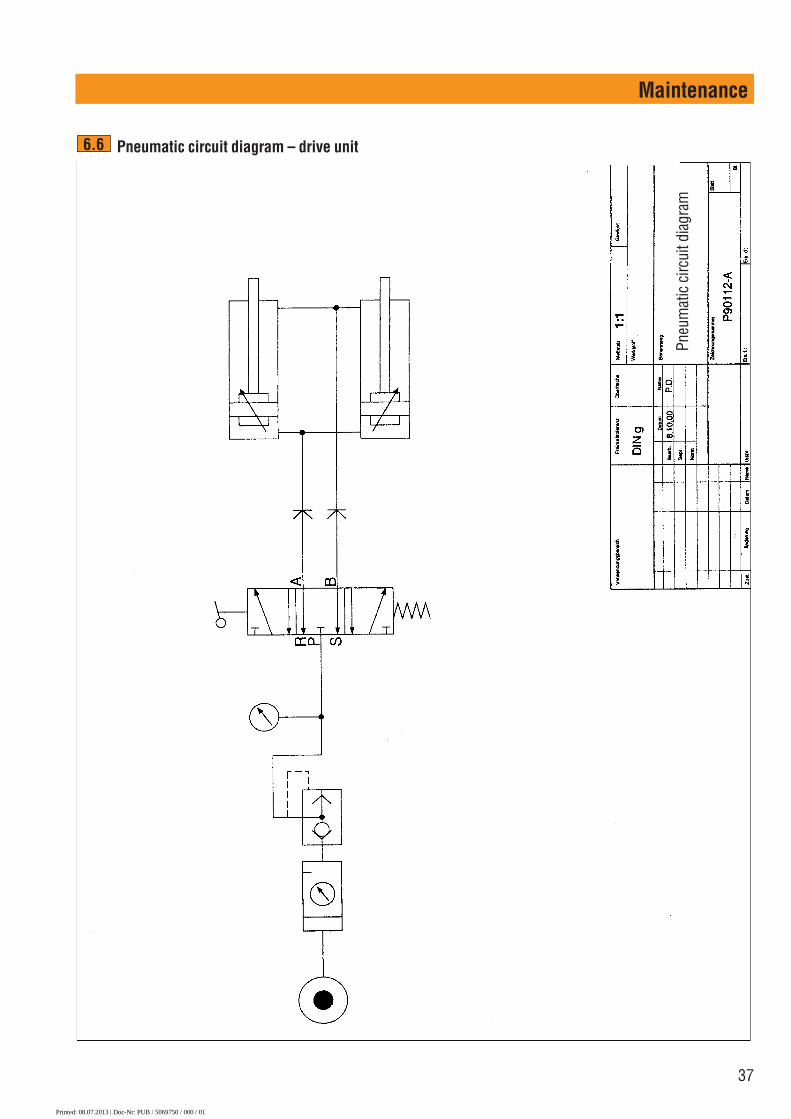
Pneumatic circuit diagram – drive unit6.6
Pneu
mat
ic c
ircui
t dia
gram
Printed: 08.07.2013 | Doc-Nr: PUB / 5069750 / 000 / 01

38
Accessories
7. Accessories
Hilti sawing wires and accessories
Safety precautions and instructions for use■ Use only sawing wires that comply with the require-
ments of ISO/IEC 13236.■ Connecting together lengths of wires of different
diameters, from different manufacturers or of dif-ferent types (e.g. electroplated or sintered beads) oruse of badly worn or out-of-round wires is not per-missible.
7.1
■ Use of damaged wires (e.g. wires with kinks, looseor shifted beads, broken strands, etc.) is not per-missible.
■ Observe the wire and wire connector manufacturer’sinstructions when connecting sawing wires and, asfar as possible, use only one wire connector in eachcomplete wire loop.
■ Use of flexible connectors greatly reduces alternat-ing bending stresses and thus reduces the probabil-ity of wire breakage due to fatigue.
■ Use only diamond wires with beads of a diameterwithin the 1/3–1/2" range. Other diameters may causethe wire to jump off the pulleys or result in damageto the running surface of the pulleys.
Specification Cutting characteristics Concrete type Reinforcement content
Good balance between cuttingCM speed and life M: medium, hard aggregates Normal
CH Specially for flint, long life H: hard, very hard aggregates Normal
20% steel Fast-cutting Universal Normal to very high
100% steel – – Only steel
Dry – Universal Normal to high
Printed: 08.07.2013 | Doc-Nr: PUB / 5069750 / 000 / 01

39
Accessories for connecting Hilti diamond wires
Accessories
Sintered Electroplated
Specification CS CM CH Concrete, 20 % steel 100 % steeldry cutting
No. of beads / m** 40 44 40 40*) 40 48*)
Bead dia. (mm) 10.5 10.5 10.5 10.2 10.2 10.8
*) each bead is crimped additionaly 1m = 3.28 ft.
DS-WS10.5 diamond wiresDesignation Designation Designation Designation Designation
Wire length DS-W 10.5 DS-W 10.5 DS-W 10.2 DS-W 10.8 DS-W 10.2(m) CM CH 20% steel 100% steel dry
per/m � 376 635 � 376 634 � 377 830 � 377 781 � 377 7821m = 3.28 ft
�
�
�
�
�
�
�
�
�
�
�
� �
Designation Package Ordering designation Item no.contents
Crimping pliers 1 DS-WSTHY � 235845For crimping connectors / repair sleevesFlexible connectors 1 DS-WCMV � 340427Quick-release typeSet of flexible connectors 5 DS-WCSet � 371383Quick-release type with pin and O-ringPin 10 DS-WP 235842Replacement pin for quick-release connectorsSleeve 5 DS-WS � 235841Repair sleeveO-ring 10 O-Ring 10/4,7×2,5 235844Fitted between connector and beadCrimping jaws 2 DS-WJ � 340426Replacement jaws for crimping pliersAssembly tool connector 1 DS-WMT � 295161For pin removalAngle grinder 1 AG125-S � 000000For cutting diamond wireCutting disc 1 AC-D 125 1mm � 304623For cutting diamond wire
Sawing wire types
Printed: 08.07.2013 | Doc-Nr: PUB / 5069750 / 000 / 01

40
DS-WRSWItem no. 315834
The release pulley is used to reduce the length of wirein contact or to increase the radius of the arc followedby the wire (avoiding a tight radius) at the rear of theobject to be cut.
7.2
Accessories
DSW-PW Plunge wheel assemblyItem no. 365428 / 247620
For plunge applications of all kinds. At least 2 pulleys arerequired. Can also be mounted on the single-pair pulleystand if necessary.
7.3
DS-WSVC vertical sawing deviceItem no. 339312
For simple, fast cuts directly below the wire drive unit.No further pulleys or wire guidance system is then used(no single-pair pulley stand). The optimum solution forapplications where the drive normally stands in a hori-zontal position. For sawing ceiling sections, supportingbeams etc.
7.4 DSW-WG wire guardItem no. 365426
Wire guards must be fitted in situations where it can-not be ensured that persons do not enter the dangerarea while the equipment is in operation, i.e. the areain which flying fragments etc. present a risk of injury,or in situations where there is a risk of damage to prop-erty or other equipment within this area.
7.5
Printed: 08.07.2013 | Doc-Nr: PUB / 5069750 / 000 / 01

41
Accessories
Accessories for setting up and operating wire saws and wire guides7.6
Accessories and wearing parts for Hilti wire saw systems7.7
Ordering designation Quantity Item no. Use
DS-WS UL tool set 424627 Wire sawscomprising:
Hilti plastic toolbox 1 206726 StorageAccessories, list of contents and uses 1 Overview of contents
Open-end / ring wrench, 19 mm 1 221189 FasteningHammer 11/2 kg 1 339303 FasteningScrewdriver, 6 mm 1 339304 FasteningBB blow-out pump � 1 59725 Blowing out anchor holesSpirit level 1 310306 MarkingWooden pencil 2 335500 MarkingCleaning cloth 1 334211 CleaningHilti spray 1 308976 LubricationHilti grease dispenser 1 203086 LubricationFlat brush 1 3206 CleaningProtective goggles 1 285775 Eye protectionJack screw DD-CS 1/2" � 3 282990 Fastening DD-CN-SML clamping nut � 3 251834 FasteningHSD-G setting tool � 1 243743 FasteningWater connection nipple � 1 356700 Water supplyGK seal 5 356701 Water seal for 356700Steel wedge � 4 41910 Securing concrete blocks
�
�
�
�
�
�
�
�
�
Ordering designation Quantity Item no. Use
Flush anchor HDI 1/2" � 50 FasteningWater supply, long � 1 339307 Water supply Water supply, flexible � 1 339379 Water supply
Printed: 08.07.2013 | Doc-Nr: PUB / 5069750 / 000 / 01

42
Troubleshooting
8. Troubleshooting
Problems or faults concerning the diamond wire
■ The DS WS15 cannot start movement of the wire
Possible cause Solution / measures
Edges of the concrete are too sharp. – Use a Hilti combihammer to round the edges and pullthe diamond wire back and forward by hand beforestarting.
A new diamond wire sticks in the kerf cut by a worn wire. – Complete the cut with the worn wire.– Mount additional return pulleys or release pulleys.
The length of contact between the diamond wire and the – Drill a hole through which the new wire can be threaded.concrete is excessive.Tension on the diamond wire is too high. – Reduce wire tension by adjusting the air pressure regu-
lation valve.
■ The diamond wire slips on the drive wheels
Possible cause Solution / measures
Insufficient tension on the diamond wire – Increase the tension by adjusting the air pressure regu-lation valve.
The rubber tyre on the drive wheel is worn excessively. – Replace the drive wheel.
■ The wire jumps off the drive wheels when starting
Possible cause Solution / measure
The starting lock was not used. – Use the starting lock (position and lock theclamping piece against the air cylinder).
8.1
Persons may enter the danger zone only when the driveunit is switched off and the drive pulley has stopped rota-ting. Press the EMERGENCY STOP button before ente-ring the danger zone.
Disconnect the equipment from the electric supply (unplugthe supply cord from the power outlet) before openingthe control unit.
Printed: 08.07.2013 | Doc-Nr: PUB / 5069750 / 000 / 01
43
Troubleshooting
■ Irregular, one-sided wear of the diamond wire
Possible cause Solution / measures
The diamond wire was not twisted before connecting the – Twist the diamond wire approx. 0,2 turns per ft ends together. (counterclockwise)■ Wire breakage directly after the connector
Possible cause Solution / measures
Cutting radius of the diamond wire in the concrete is too tight. – Mount additional return pulleys.Wire connector is too long. – Fit shorter wire connector.
– Use the quick-release connectors recommended byHilti instead of rigid connectors.
■ The diamond wire pulls out of the crimped connector
Possible cause Solution / measures
Incorrectly adjusted crimping pliers Check how the crimping pliers are set.Insufficient pressure applied to the crimping pliers – Minimum crimping pressure is 7 t (Hilti crimping
pliers = 8 t)Incorrect or worn crimping jaws – Check the crimping jaws and replace if necessary.The wire was not pushed far enough into the connector. – The wire must always be pushed into the connector as
far as it will go. The end of the wire must be cut cleanlyand in accordance with instructions.
■ The diamond wire jumps about and vibrates very strongly
Possible cause Solution / measures
Insufficient tension on the wire – Increase the wire tension by adjusting the air pressureregulation.
Guide pulleys are too far apart (free length of wire is too long). – Mount additional pulley stands.– Fit a shorter diamond wire.– Position the drive unit closer to the object being cut.
■ The diamond wire vibrates very strongly at a high frequency
Possible cause Solution / measures
Tension on the wire is too high. – Reduce the tension on the wire by adjusting the airpressure regulation.
The saw is running at the wrong speed. – Set the correct speed.
Printed: 08.07.2013 | Doc-Nr: PUB / 5069750 / 000 / 01

44
Troubleshooting
■ The diamond wire wears too quickly
Possible cause Solution / measures
Drive speed is too low and wire cutting speed is thus also – Increase drive speed or, respectively, cutting speed.too low.Inadequate cooling of the diamond wire – Set up more water nozzles at the cutting face.Wire cutting length too short – Increase the cutting length (length of contact).(length of contact between the wire and the concrete)Wire tension too high relative to length of cut. – Reduce the tension on the wire by adjusting the air
pressure regulation valve.Very abrasive material being cut. – Select a different diamond wire specification.The direction in which the wire runs is changed continually. – Always fit the diamond wire so that it runs in the same,
specified direction.
■ The diamond wire collapses(The diamond beads, connecting pieces and separating springs are bunched together on the wire.)
Possible cause Solution / measures
Diamond wire not cooled adequately or not cooled at all – Always ensure that sufficient water reaches the cuttingface.
The diamond wire becomes stuck in the kerf and stalls – Steel wedges must be used to prevent movement of during sawing. the concrete sections.
– Loose fragments or aggregates must be removed fromthe kerf.
Printed: 08.07.2013 | Doc-Nr: PUB / 5069750 / 000 / 01
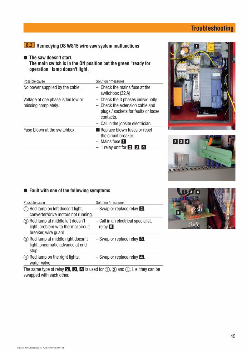
45
Troubleshooting
Remedying DS WS15 wire saw system malfunctions
■ The saw doesn't start.The main switch is in the ON position but the green “ready for operation” lamp doesn't light.
Possible cause Solution / measures
No power supplied by the cable. – Check the mains fuse at theswitchbox (32 A)
Voltage of one phase is too low or – Check the 3 phases individually.missing completely. – Check the extension cable and
plugs / sockets for faults or loosecontacts.
– Call in the jobsite electrician.Fuse blown at the switchbox. ■ Replace blown fuses or reset
– the circuit breaker.– Mains fuse �– 1 relay unit for �, �, �
8.2
■ Fault with one of the following symptoms
Possible cause Solution / measures
� Red lamp on left doesn’t light, – Swap or replace relay �. converter/drive motors not running.
� Red lamp at middle left doesn’t – Call in an electrical specialist,light, problem with thermal circuit relay �breaker, wire guard.
� Red lamp at middle right doesn’t – Swap or replace relay �. light, pneumatic advance at end stop
� Red lamp on the right lights, – Swap or replace relay �. water valve
The same type of relay �, �, � is used for �, � and �, i. e. they can beswapped with each other.
1
2 3 4
2 3 4
�
�
�
�5
Printed: 08.07.2013 | Doc-Nr: PUB / 5069750 / 000 / 01

46
Troubleshooting
■ The DS WS15 doesn't start.The green “ready for operation” lamp lights together with the red“error” lamp.
Possible cause Solution / measures
Power cable or control cable from the – Connect the cables.drive is not connected to the control unit.The side cover is not fitted on the – Fit the side cover.machine �The motors are too hot. – Use more cooling water or colder
water.The current converter is overloaded. – Do not work at above 30 A.
– Check the filter in the base of thecontrol unit (a flow of air must befelt at the top opening on the con-trol unit).
Resetting the converter:Switch off at the main switch andwait approx. 1 minute before switch-ing on again.
■ The DS WS15 doesn't start.The green “ready for operation” lamp lights.
Possible cause Solution / measures
The EMERGENCY OFF button is – Release the EMERGENCY OFF pressed in. button.
■ The DS WS15 cuts out while running and cannot be restarted.The green “ready for operation” lamp lights together with the yel-low “pneumatic advance” lamp.
Possible cause Solution / measures
The air cylinders and carriage are in – Reduce the wire length (wind onto the end position. the storage pulleys) or move the
machine back.
5
Printed: 08.07.2013 | Doc-Nr: PUB / 5069750 / 000 / 01

47
Troubleshooting
■ High current input (more than 40 A) or the converter is overloaded.
Possible cause Solution / measures
Wire tension is too high. – Reduce the tension by adjustingthe air pressure regulating valve�.
7
One phase is missing. – Check the mains supply.
Printed: 08.07.2013 | Doc-Nr: PUB / 5069750 / 000 / 01
48
Manufacturer's warranty – tools / Disposal
9. Manufacturer's warranty – tools
Hilti warrants that the tool supplied is free of defectsin material and workmanship. This warranty is valid solong as the tool is operated and handled correctly,cleaned and serviced properly and in accordance withthe Hilti Operating Instructions, and the technical sys-tem is maintained. This means that only original Hilticonsumables, components and spare parts may beused in the tool.
This warranty provides the free-of-charge repair orreplacement of defective parts only over the entire lifes-pan of the tool. Parts requiring repair or replacementas a result of normal wear and tear are not covered bythis warranty.
Additional claims are excluded, unless stringentnational rules prohibit such exclusion. In particular,Hilti is not obligated for direct, indirect, incidentalor consequential damages, losses or expenses inconnection with, or by reason of, the use of, or inabil-ity to use the tool for any purpose. Implied warrantiesof merchantability or fitness for a particular purposeare specifically excluded.
For repair or replacement, send tool or related partsimmediately upon discovery of the defect to the addressof the local Hilti marketing organization provided.
This constitutes Hilti's entire obligation with regard towarranty and supersedes all prior or contemporane-ous comments and oral or written agreements con-cerning warranties.
Most of the materials from which Hilti appliances aremanufactured can be recycled.The materials must be correctly separated before theycan be recycled.Hilti has already made arrangements in many countriesfor taking back your old appliance for recycling. Please ask your Hilti customer service department or aHilti sales representative for further information.
Return waste material for recycling
10. Diposal
Printed: 08.07.2013 | Doc-Nr: PUB / 5069750 / 000 / 01

49
Printed: 08.07.2013 | Doc-Nr: PUB / 5069750 / 000 / 01

50
Printed: 08.07.2013 | Doc-Nr: PUB / 5069750 / 000 / 01

51
Printed: 08.07.2013 | Doc-Nr: PUB / 5069750 / 000 / 01

*426571*
4265
71Hilti = registered trademark of Hilti Corp., Schaan W 2557 I 1212 I 1-en_USA I 1 Printed in Liechtenstein © 2012Right of technical and programme changes reserved S. E. & O.
Hilti CorporationLI-9494 SchaanTel.: +423 / 234 21 11Fax:+423 / 234 29 65www.hilti.com
426571 / A2
Printed: 08.07.2013 | Doc-Nr: PUB / 5069750 / 000 / 01