b100 series quick start guide - dynamic ratings · b100 series quick start guide ... b100 series...
TRANSCRIPT

B100 Series Quick Start Guide Setup and Configuration
MONITORING, CONTROL AND COMMUNICATION SOLUTIONS FOR ELECTRICAL POWER APPARATUS
Setup and Configuration
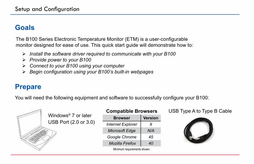
Prepare
Goals
You will need the following equipment and software to successfully configure your B100:
The B100 Series Electronic Temperature Monitor (ETM) is a user-configurablemonitor designed for ease of use. This quick start guide will demonstrate how to:
¾ Install the software driver required to communicate with your B100 ¾ Provide power to your B100 ¾ Connect to your B100 using your computer ¾ Begin configuration using your B100’s built-in webpages
Browser VersionInternet Explorer 9Microsoft Edge N/AGoogle Chrome 45 Mozilla Firefox 40
Compatible Browsers
Minimum requirements shown.
Windows® 7 or laterUSB Port (2.0 or 3.0)
USB Type A to Type B Cable
B100 Series Monitor
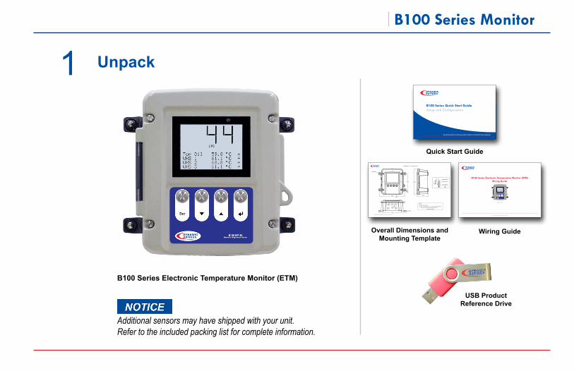
1 Unpack
B100 Series Electronic Temperature Monitor (ETM)
USB Product Reference Drive
Quick Start Guide
B100 Series Quick Start Guide Setup and Configuration
Monitoring, Control and Communication Solutions for Electrical Power Apparatus
Overall Dimensions and Mounting Template
B100 Series | Overall Dimensions
0.25 in
6 mm
0.48 in12 mm
11.32 in287 mm
12.44 in315 mm
7.30 in185 mm
11.68 in296 mm
5.11 in129 mm
1 in.M25
1 in.M25 .75 in.
M20
.75 in.M20
.75 in.M20
.75 in.M20
See Detail A
Rubber Grommet
Metal Ferrule
Rubber Grommet
Detail A
1
1
NOTES1 Entry Port Locations.2 Refer to the B100 Series Hole Location Drilling Template on
the reverse of this page for mounting instructions.
NOT ACTUAL SIZE
©2016 Dynamic Ratings This information subject to change without notice. All rights reserved.
0.25 in
6 mm
0.48 in12 mm
11.32 in287 mm
12.44 in315 mm
7.30 in185 mm
11.68 in296 mm
5.11 in129 mm
1 in.M25
1 in.M25 .75 in.
M20
.75 in.M20
.75 in.M20
.75 in.M20
See Detail A
Rubber Grommet
Metal Ferrule
Rubber Grommet
Detail A
2
Additional sensors may have shipped with your unit. Refer to the included packing list for complete information.
Wiring Guide
B100 Series Electronic Temperature Monitor (ETM) Wiring Guide
Rev 8
www.dynamicratings.com
Setup and Configuration
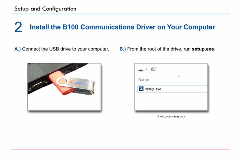
2 Install the B100 Communications Driver on Your Computer
A.) Connect the USB drive to your computer. B.) From the root of the drive, run setup.exe.
Drive contents may vary.
B100 Series Monitor
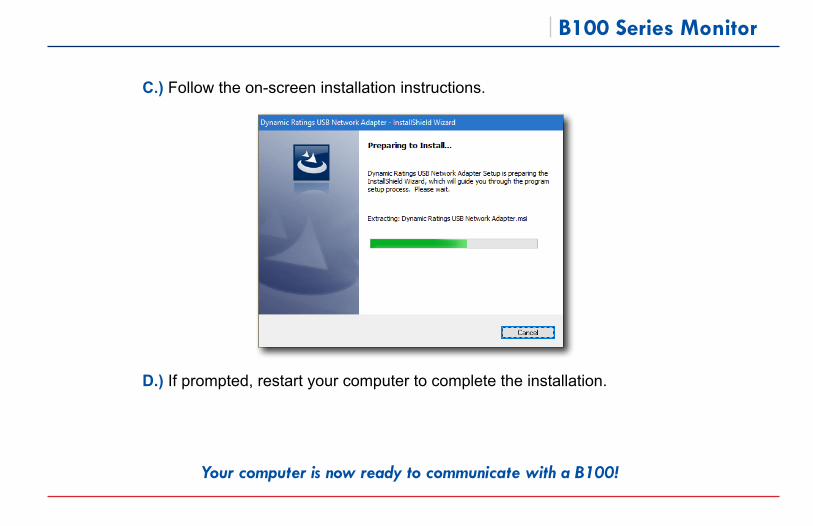
C.) Follow the on-screen installation instructions.
D.) If prompted, restart your computer to complete the installation.
Your computer is now ready to communicate with a B100!
Setup and Configuration
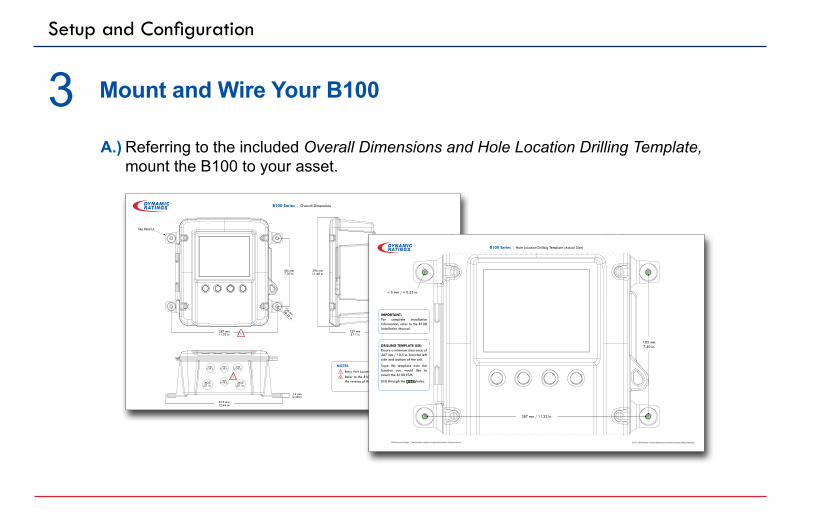
3 Mount and Wire Your B100
Referring to the included Overall Dimensions and Hole Location Drilling Template, mount the B100 to your asset.
A.)
B100 Series | Overall Dimensions
0.25 in
6 mm
0.48 in12 mm
11.32 in287 mm
12.44 in315 mm
7.30 in185 mm
11.68 in296 mm
5.11 in129 mm
1 in.M25
1 in.M25 .75 in.
M20
.75 in.M20
.75 in.M20
.75 in.M20
See Detail A
Rubber Grommet
Metal Ferrule
Rubber Grommet
Detail A
1
1
NOTES1 Entry Port Locations.2 Refer to the B100 Series Hole Location Drilling Template on
the reverse of this page for mounting instructions.
NOT ACTUAL SIZE
©2016 Dynamic Ratings This information subject to change without notice. All rights reserved.
0.25 in
6 mm
0.48 in12 mm
11.32 in287 mm
12.44 in315 mm
7.30 in185 mm
11.68 in296 mm
5.11 in129 mm
1 in.M25
1 in.M25 .75 in.
M20
.75 in.M20
.75 in.M20
.75 in.M20
See Detail A
Rubber Grommet
Metal Ferrule
Rubber Grommet
Detail A
2 ⌀ 6 mm / ⌀ 0.25 in.
161113 B100 Series Overall Dimensions and Hole Location Drilling Template
DRILLING TEMPLATE USE:Ensure a minimum clearance of 267 mm / 10.5 in. from the left side and bottom of the unit.
Tape this template over the location you would like to mount the B100 ETM.
Drill through the green holes.
IMPORTANT: For complete installation information, refer to the B100 Installation Manual.
B100 Series | Hole Location Drilling Template (Actual Size)
287 mm / 11.32 in.
185 mm7.30 in.
©2016 Dynamic Ratings This information subject to change without notice. All rights reserved.

B100 Series Monitor
Using a flathead screwdriver, open the B100 by turning the four screws on the front of the unit counterclockwise. The screws do not need to be completely removed for the unit to open.
B.)
To wire the B100 for your application, refer to the included B100 Wiring Guide.
Do not wire the B100 for power until you have connected all desired inputs and outputs. Instructions for powering the B100 are given on the next page.
C.)
B100 Series Electronic Temperature Monitor (ETM) Wiring Guide
Rev 8
www.dynamicratings.com
Electrical work must be performed by qualified personnel only. All electrical work must conform to your local regulations and national electrical codes.

Setup and Configuration
A.) Properly wire a breaker-protected power source to the black input connector per the rated input ranges on the product.
4 Power Your B100
Example only. The rated input can change based on the B100’s hardware configuration. Refer to the label.
Electrical work must be performed by qualified personnel only. All electrical work must conform to your local regulations and national electrical codes.
For DC input voltage applications, the installer is to run a separate wire to ensure a bonded earth ground.
North American Wiring Example
European Union, Australian,
New Zealand Wiring Example
B100 Series Monitor
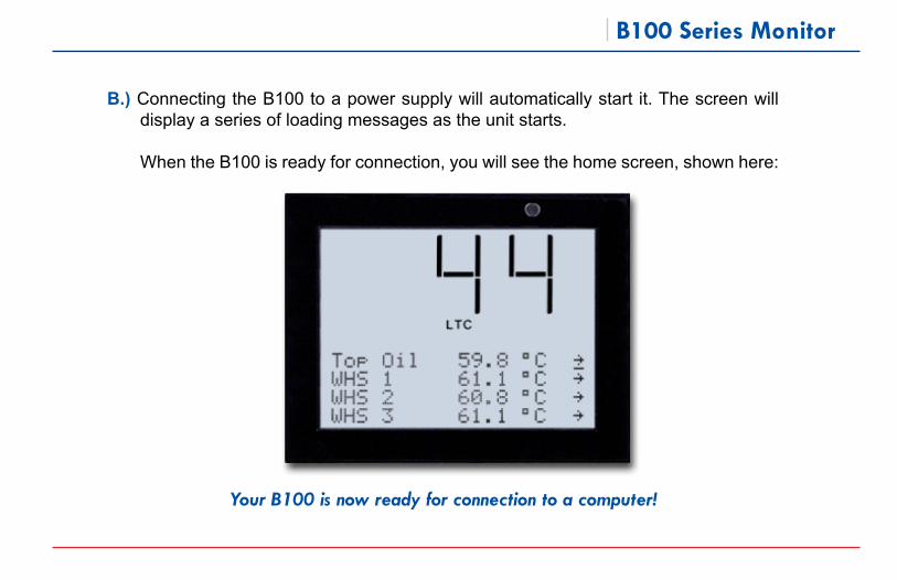
B.) Connecting the B100 to a power supply will automatically start it. The screen will display a series of loading messages as the unit starts.
When the B100 is ready for connection, you will see the home screen, shown here:
Your B100 is now ready for connection to a computer!
Setup and Configuration
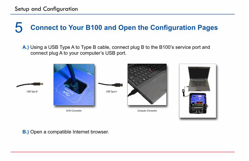
5 Connect to Your B100 and Open the Configuration Pages
B.) Open a compatible Internet browser.
A.) Using a USB Type A to Type B cable, connect plug B to the B100’s service port and connect plug A to your computer’s USB port.
B100 Connection
USB Type B USB Type A
Computer Connection
B100 Series Monitor
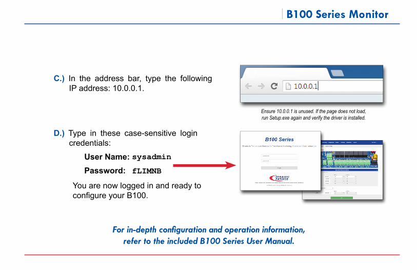
You are now logged in and ready to configure your B100.
For in-depth configuration and operation information, refer to the included B100 Series User Manual.
D.) Type in these case-sensitive login credentials:
User Name: Password:
C.) In the address bar, type the following IP address: 10.0.0.1.
Ensure 10.0.0.1 is unused. If the page does not load, run Setup.exe again and verify the driver is installed.
fLIMNB
sysadmin
Reference DocumentsThe included Dynamic Ratings USB Product Reference Drive includes:
B100 Series ManualsOverall Dimensions and Hole Location Drilling Template B100 Wiring GuideUSB Remote NDIS Network Device Driver (setup.exe)
Microsoft® Windows® is a registered trademark of Microsoft Corporation.
Asia / Africa / Oceania+61 3 [email protected] / Europe+1 262 [email protected]
www.dynamicratings.com
©2017 Dynamic Ratings This information subject to change without notice. All rights reserved. 170208 B100 Series Quick Start Guide
For product support, please contact Dynamic Ratings: