b065provisionalusermanualv1.0 db broadcast ltd ii provisional version 1.0 db broadcast ltd has made...
TRANSCRIPT

B065B065 Rack Controller Module, RS232
and Ethernet SNMP-V1
Handbook Provisional Version 1.0

Rack Controller Module B065
2007 dB Broadcast Ltd ii Provisional Version 1.0
dB Broadcast Ltd has made every effort to ensure the accuracy of information contained within thisdocument which is nevertheless supplied for information purposes only and does not constitute any
form of warranty or guarantee.
All trademarks acknowledged.
The information in this document is subject to change without notice.
dB Broadcast LtdRegistered Office:
Kestrel HouseSedgeway Business Park
WitchfordEly
CambridgeshireUK
CB6 2HYTel: +44 (0) 1353 661117
Fax: +44 (0) 1353 665617Email: [email protected]
Web: www.dbbroadcast.co.ukRegistered in England No. 2709677

Rack Controller Module B065 Document history
2007 dB Broadcast Ltd iii Provisional Version 1.0
DDooccuummeenntt hhiissttoorryy
Date of first publication 14th
June 2007
Current issue and date 1.0 / 22nd December 2007
Firmware versions

Rack Controller Module B065 Document history
2007 dB Broadcast Ltd iv Provisional Version 1.0
CCoonntteennttss
DOCUMENT HISTORY III
INTRODUCTION 1
The B065 Rack Controller Module 1
Features 2
Applications 2
GENERAL SAFETY SUMMARY 3
INSTALLATION 5
Rear I/O 5
Front panel RS232 6
Rear panel RS232/485 6
Ethernet port 7
DARTbus port 7
GPI I/O port 8
Reset/Status port 9
FUNCTIONAL CHECK 9
NETWORK CONFIGURATION 10
INTRODUCTION 10
EQUIPMENT REQUIRED 10
FRAME PREPERATION 10
B070/V6081 INTERFACE CARD TESTS 11
USING B067 SNMP REMOTE CONTROL SOFTWARE 12
Installation 12
Configuration 12
USING A TERMINAL EMULATOR 14
Configuration commands 15
USING A USB RS232 PORT 16
USING A CROSSOVER ETHERNET CABLE 17
OPERATION 19
Front panel features 19

Rack Controller Module B065 Document history
2007 dB Broadcast Ltd v Provisional Version 1.0
Local RS232 control 19
Remote control 19
THE COMMAND-LINE INTERFACE 21
Serial port connection 21
Remote control protocol 21
DEFAULT SETTINGS 24
UPDATING FIRMWARE 25
SPECIFICATION 27
ORDERING INFORMATION 30

Rack Controller Module B065
2007 dB Broadcast Ltd 1 Provisional Version 1.0
IInnttrroodduuccttiioonn
The B065 Rack Controller Module
The B065 module enables remote control of the Hawkeye video decoders, audio decoders,
receivers and other Hawkeye modules via RS232 or Ethernet SNMP.
The B065 automatically detects compatible modules in the V1606 (3RU) frame in which it is
fitted and provides a single point of control.
Status is indicated on the front panel. When used with the optional B067 software a graphical
representation of chassis contents, alarm states and logs may be obtained.
Additionally, where fail-safe operation is required, a custom algorithm may be loaded to
provide a fully autonomous, in-chassis, redundancy solution. For applications using Simple
Network Management Protocol (SNMP) based network management systems Management
Information Base objects (MIBs) are available.
Figure 1: B065 Rack Controller
Note: The B065 requires a V6081 interface module to be fitted in the same frame.

Rack Controller Module B065 Introduction
2007 dB Broadcast Ltd 2 Provisional Version 1.0
Features
An Ethernet port, a CAN control port and two RS232 ports
Alarm reporting via SNMP traps
SNMP v1 Protocol conversion to CAN control bus (DARTnet)
Alarm reporting via SNMP traps
Backup of module configurations
Alarm aggregation for all modules fitted within the same frame
Frame environmental status feedback
Module status indicator available on front panel
Low power consumption
Applications
Remote management of Hawkeye modules via RS232 or Ethernet
Internal redundancy management platform
General purpose interface for modules fitted within the frame

Rack Controller Module B065
2007 dB Broadcast Ltd 3 Provisional Version 1.0
GGeenneerraall ssaaffeettyy ssuummmmaarryy
Precautions to avoid personal injury, fire or product damage.
Every care has been taken in the design, manufacture, assembly and testing of this product
to obviate health and safety risks to personnel and to prevent fire or other hazards. However,
please review the following safety precautions for continued protection.
General use. This product must only be used as specified in this manual. Failure to follow
any ratings or directions for use may impair the protection provided.
On receipt of the product. Verify there is no damage and that all accessories are present .
Suspected damage or failure. Do not operate the product. Have it inspected by qualified
service personnel or contact dB Broadcast or an authorised distributor.
Operating environment. The unit is for indoor use only. See the Specification chapter for
further environmental, physical, certification and safety information.
Do not operate in wet or damp conditions.
Do not operate in an explosive atmosphere .
Power cable. Use only a power cable specified for this product and certified safe for the
country of use.
Grounding. This product must be grounded. Before making any signal connections, ensure
that the product is grounded. The product is grounded through the power cable. To avoid
electric shock under fault conditions, the protective grounding conductor within the power
cable must be connected to an earth terminal of the building in which the product is located.
Mains supply voltage and fuse ratings. See the Specification chapter. All ratings must be
observed.
Ventilation. To prevent overheating do not obstruct ventilation holes.
Cuts and abrasions. When handling the equipment, guard against cuts or abrasions from
metal parts of the case or components.
CAUTION. Caution statements identify conditions or practices that could result in damage to
this product or other property.
Toxic content. Unwanted or obsolete components must be disposed of safely as some may
release toxic vapours if incinerated.

Rack Controller Module B065 General safety summary
2007 dB Broadcast Ltd 4 Provisional Version 1.0
In case of difficulty. Please refer to dB Broadcast.
Lithium battery
A lithium battery may be located in this product to provide back up for a real-time clock. In
normal operation this battery has a life in excess of 5 years. If the real-time clock’s operation
becomes erratic when cycling the power, then the battery may need replacing. Battery
replacement should only be performed by a ‘skilled and competent technician’, or by
returning to db Broadcast for repair.
CAUTION: Danger of explosion if battery is incorrectly replaced.
Product damage precautions
Take anti-static precautions
Since this unit contains exposed PCB and electronic components, ensure proper anti-static
precautions are observed when handing this equipment.
Provide proper ventilation
To prevent product overheating, provide proper ventilation.
Do not operate with suspected failures
If you suspect there is damage to this product, have it inspected by qualified service
personnel.
There are no user serviceable parts
Return to dB Broadcast or an authorized distributor for repair/service.
Installation
On receipt of the unit, open the box and verify that the unit and all accessory items included.
Save the shipping carton and packing materials in case it becomes necessary to ship the unit
to dB Broadcast for service or repair.

Rack Controller Module B065
2007 dB Broadcast Ltd 5 Provisional Version 1.0
IInnssttaallllaattiioonn
The rear panel assembly must be installed prior to fitting the main module.
To do this, remove the blanking plate from the required slot in the rear of the
frame.
WARNING: Always remove power whilst fitting the rear module.
Insert the rear panel assembly taking care to align the control and power
pins at the top and bottom of the rear panel correctly. The audio connectors
go towards the bottom of the rack.
CAUTION: Damage to the module and/or frame may occur if the rear panel
assembly is not the correct type or is incorrectly installed.
Secure the rear panel assembly to the rack system using the 4 screws that
held the blanking plate (M2.5 x 10mm).
Pull down the front panel and insert the module into the appropriate slot
taking care to ensure it is within the top and bottom guides. Push the
module fully home into the DIN connector in the rear panel assembly.
To remove the module from the frame pull the unit from the front of the frame using the
handle.
Rear I/O
VB190 Connector signal
RS232 A female 9-pin sub-miniature D-Type connector, providing a bi-directional serial connection to auxiliary equipment complying with
RS232 or RS485 signal levels.
Ethernet One female 8-pin RJ-45 connector, providing a bi-directionalconnection to a 10baseT hub on a local area network.
DARTbus One female 8-pin RJ-45 socket for connection to the DART socket on
the V1606 frame using a UTP patch cable. Enables a V6081 modulein the same frame.
GPI 0-3; 4-7;8-11; 12-15
Four 5-pin connectors providing access to the V6081 ControllerGeneral Purpose Interface I/O.
Refer to GPI section for a full description.
Reset/Status A 5-pin connector providing connection to a telemetry control system.Refer to Reset/Status section for a full description.
WARNING: Ensure that the Dart bus cable is plugged into the Dartbus conector. Damage
will occur if this cable is plugged into the Ethernet port

Rack Controller Module B065 Installation
2007 dB Broadcast Ltd 6 Provisional Version 1.0
Front panel RS232
RS232 – 9 way ‘D’ type
PIN SIGNAL
1 N/C
2 Txd - Transmit data (to host)
3 Rxd - Receive data (from host)
4 N/C
5 Signal ground
6 N/C
7 CTS – Clear to send (from host)
8 RTS – Request to send (to host)
9 N/C
Shell Chassis ground
Rear panel RS232/485
RS232 – 9 way ‘D’ type
PIN RS232
SIGNAL
RS485
SIGNAL
1 N/C N/C
2 Txd TX
3 Rxd RX
4 N/C N/C
5 SGND SGND
6 N/C N/C
7 CTS RX+
8 RTS TX+
9 N/C N/C
Shell Chassis GND Chassis GND
Rack Controller Module B065 Installation
2007 dB Broadcast Ltd 7 Provisional Version 1.0
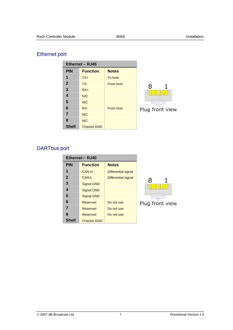
Ethernet port
Ethernet – RJ45
PIN Function Notes
1 TX+ To host
2 TX- From host
3 RX+
4 N/C
5 N/C
6 RX- From host
7 N/C
8 N/C
Shell Chassis GND
DARTbus port
Ethernet – RJ45
PIN Function Notes
1 CAN-H Differential signal
2 CAN-L Differential signal
3 Signal GND
4 Signal GND
5 Signal GND
6 Reserved Do not use
7 Reserved Do not use
8 Reserved Do not use
Shell Chassis GND

Rack Controller Module B065 Installation
2007 dB Broadcast Ltd 8 Provisional Version 1.0
GPI I/O port
GPIs provide basic telemetry control and monitoring and consists of a block of 16 signals
located on the rear panel. Depending upon the application, each GPI signal can be
configured as either an input or output.
GPI
PIN GPI 0-3 GPI 4-7 GPI 8-11 GPI 12-15
1 0 4 8 12
2 1 5 9 13
3 GND GND GND GND
4 2 6 10 14
5 3 7 11 15
Inputs
A GPI signal configured as an input can be used to monitor telemetry outputs from other
equipment or provide basic system control through a closing contact (switch, relay, etc).
Typical GPI input configuration
A GPI input is deemed inactive if the input is open-circuit or externally pulled up to +5V. It is
deemed active if the input is connected or driven to 0V. GPI inputs are internally integrated to
prevent contact bounce from causing spurious inputs.
Outputs
A GPI signal configured as an output can drive telemetry inputs on other equipment or
provide basic system monitoring through visual indicators (LEDs, lamps, etc).
Typical GPI output configuration
The GPI output in the inactive state does not provide a current source since the output drive
transistor is switched off.
The GPI output in the active state is capable of sinking up to 10mA when the output drive
transistor is switched on. GPI outputs are internally limited to 10mA and it is not necessary to
provide limiting resistors for external indicators.

Rack Controller Module B065 Installation
2007 dB Broadcast Ltd 9 Provisional Version 1.0
CAUTION: GPI signals use TTL voltage levels between 0 and 5V with a maximum output
current load of 10mA. It is important NOT to exceed their maximum ratings as this may result
in damage or malfunction of the module.
Reset/Status port
Reset/Status
PIN Function Description
1 NO Fail relay normally closed contact
2 COM Fail relay common contact
3 NO Fail relay normally open contact
4 R- Reset input -
5 R+ Reset input +
The Reset/Status Port located on the rear panel allows the module to be monitored and/or
reset remotely.
Remote monitoring
The status signals of the Reset/Status Port, NO/COM/NC, are a set of isolated relay
contacts. In normal operation the COM (common) and NO (normally open) signals are
connected. In a fault condition (or not powered) the COM and NC (normally closed) signals
are connected.
Reset
Reset input + (pin 5) and Reset Input - (pin 4) allow module to be reset from an external
source such as a relay contact or switch.
To reset the module connect R– to R+ for longer than 10ms.
Functional check
To ensure the B065 Rack Controller is operating correctly complete the following procedures.
1. Power up the rack and ensure the green power indicator (+V) on the front panel is
illuminated.
2. Follow the configuration steps in the next chapter Network configuration.

Rack Controller Module B065
2007 dB Broadcast Ltd 10 Provisional Version 1.0
NNeettwwoorrkk ccoonnffiigguurraattiioonn
Introduction
This document describes the stages needed to configure a B065 Rack Controller Card for
use on an IP/Ethernet based network using the B067 SNMP Remote Control Software or a
terminal emulator.
Note: Before connection to a network, contact the network administrator and request the
following details:
An IP Address for every B065 to be configured
The correct network subnet to use
The IP address of the default gateway
The IP address of the SNMP trap destination
Use of incorrect addresses will not only prevent access to the B065 Rack Controller Card but
could cause the network to malfunction.
Equipment required
RS232 1:1 Lead (9 pin Male to Female)
B067 SNMP Remote Control Software or a terminal emulator
Insulated pot tweaker
Optionally an Ethernet crossover cable
The Ethernet crossover cable is suggested to allow the configuration to be tested prior to
connection to a network.
Frame preperation
Install the B065 card and rear connector in slot 14, next to the PSU with the power off.
The B065 card must be connected to the frame system, using the supplied cable. The frame
Dartnet and the B065 Dart net connectors are adjacent.
WARNING: Do not connect the Rack Dartnet connector to the Ethernet connector;
permanent damage to the B065 card can result.

Rack Controller Module B065 Network configuration
2007 dB Broadcast Ltd 11 Provisional Version 1.0
B070/V6081 interface card tests
1. The Hawkeye B070 (or Vistek V6081) module, located above the power supplies, needs
to be checked for correct firmware revision 01.00.11, printed on U13.
2. Using ESD precautions, remove the B070/V6081 module. There are two rotary switches,
which must be set as follows: SW3 = 0 and SW4 = 1.
3. Replace the B070/V6081 module into the rack and power the rack.
4. Push button function switch, SW1, is located behind the module handle behind the power
LED. Push this switch, using an insulated tool, while observing the LED display.
5. Press the switch 5 times and the LED should display r11.
If the display indicates a different r number do the following:
6. Remove power from the rack and press the front panel push button detailed above. Re-
power the rack with the button pushed.
When the B070/V6081 has completed the boot up sequence the display should read AO1.
7. Now press the switch 5 times and confirm that the display shows r11.
After a short period, the display will revert back to AO1.

Rack Controller Module B065 Network configuration
2007 dB Broadcast Ltd 12 Provisional Version 1.0
Using B067 SNMP Remote Control Software
Installation
Start the CD and then click on install and follow the instructions. Answer YES to driver
revisions.
Connect the PC RS232 to the B065 front panel RS232 connector. If the PC does not have a
RS232 port, see Using a USB RS232 port.
From Start/All Programs/ click and run the B067 SNMP Remote Control Software Rack
Control.
Configuration
The GUI should run and a frame with at least one control module and power supply should
appear on the screen.
On the toolbar, select System and then Comms Options. From the Communications options,
select RS232 control and select the relevant RS232 serial port. Select OK and return to the
main rack layout screen. The GUI RS232 port must match the PC RS232 port connection.
The main screen display should now have green LED’s for Communications status, PC and
Rack.

Rack Controller Module B065 Network configuration
2007 dB Broadcast Ltd 13 Provisional Version 1.0
If the PC LED is red, check the RS232 connection and RS232 port used by the PC. If the
Rack LED is RED, check that the B065 is connected to the frame using the Dartnet
connector.
Click on the B065 control card (Slot14) and the DTCC control card page will appear.
If the data is as below, check the RS232 connection.
Client IP Address 0. 0. 0. 0.
TFTP Server IP Address 0. 0. 0. 0.
Gateway 0. 0. 0. 0.
Subnet Mask 0. 0. 0. 0.
To change the B065 Client IP Address, subnet mask, gateway and TFTP Server to those
given by your IT manager, click on the control card and click the appropriate SET button and
fill in the details required.
Close the B065 card and re-power the rack.
On the control GUI, select RACK, CONFIGURE and then Change rack1 to start. Set the IP
address here to match the control card setting. In this example set 192.168.0.115. Enter a
suitable rack name i.e Test Rack 1, and then select the number of PSU’s fitted. Finally,
choose Set Active and then Close.
The B065 control card and the GUI are now using the same IP address. In the GUI, select
SYSTEM, COMMS OPTIONS and click on SNMPv1 and close the page.

Rack Controller Module B065 Network configuration
2007 dB Broadcast Ltd 14 Provisional Version 1.0
Using a Terminal Emulator
This section describes how to configure the B065 without access to the B067 control
software. It is written assuming the user is familiar with a terminal emulator. HyperTerm is
recommended but most terminal emulators are suitable:
The terminal emulator must be configured using the following settings:
Baudrate 38400
Parity None (N)
Stop bits 1
Handshaking Hardware (RTS/CTS)
Line ending Carriage return only (‘\r’ or code 13)
Incoming conversions Append linefeed (‘\n’ or 10) to carriage return.
In Hyperterm this appears as:
And for ASCII configuration

Rack Controller Module B065 Network configuration
2007 dB Broadcast Ltd 15 Provisional Version 1.0
Configuration commands
CLIENT (B065 Controller Card Address)
CLIENT xxx.xxx.xxx.xxx
Where xxx represents part of the address in the range 0..255
This sets the address of the card. During initial programming the card address is
192.168.0.111 so we set it as such:
CLIENT 192.168.0.111
SERVER
SERVER <Address of TFTP Server>
This sets the TFTP server address
GATEWAY
GATEWAY 192.168.0.1
Sets the default gateway; i.e. the address of the router used to reach addresses that don't
appear on the current subnet.
NETMASK
NETMASK 255.255.255.0
The network mask used to define which bits of the address define the current subnet and
which the device address on that subnet.

Rack Controller Module B065 Network configuration
2007 dB Broadcast Ltd 16 Provisional Version 1.0
Using a USB RS232 port
Install a USB RS232 port following the supplier’s instructions. Once installed the RS232 port
is probably located at Port8 or similar.
To check to see which port has been allocated do the following:
1) Under Control Panel, select System,
Hardware and finally Device Manager.
2) Then click on Ports (com and LPT).
3) Select Advanced to allow
the com port number to be
configured:
4) Select a free port in the range 1 to 4 from the COM Port Number drop down menu.

Rack Controller Module B065 Network configuration
2007 dB Broadcast Ltd 17 Provisional Version 1.0
Using a crossover Ethernet cable
As an alternative to network connection the PC may be connected directly to the B065 Rack
Controller Card using a CROSS OVER Ethernet lead. This is an ideal way to configure a
B065 before installation to minimise downtime.
Navigate to Network Connections. The method depends on the operating system, for
XP/Win2000 it can be found via the Control Panel.
Highlight the active Local area connection:
right click and select Properties.
Select Internet Protocol (TCP/IP) (or IP
Version 4 for Windows Vista), and click on
Properties.
A General page will open allowing automatic
or manual IP settings.
Note: Make a note of the current settings as
they will be required to return the PC to it’s
previous configuration before returning to a
cooperate network. Failure to correctly reset
the PC IP settings could cause the network to
malfunction as well as preventing
reconnection.
Select Use the following IP Address and then set it to values recommended by your network
administrator.

Rack Controller Module B065 Network configuration
2007 dB Broadcast Ltd 18 Provisional Version 1.0
For testing or demonstrations we recommend:
Client IP Address 192. 168. 0. 106.
Subnet Mask 255. 255. 255. 255.
Gateway 192. 168. 0. 1.
Click OK to exit the TCP/IP properties menu,
Tip: Disable WIFI for the time being.
Navigate to the COMMAND PROMPT (in XP go via Programs >> Accessories).
From the command line type the following:
Ping <ip address of B065>
Which for the generic configuration is:
Ping 192.168.0.111
The following responses will be seen.
Pinging 192.168.0.111 with 32 bytes of data:
Reply from 192.168.0.111: bytes = 32 time=1ms TTL=255
Reply from 192.168.0.111: bytes = 32 time<1ms TTL=255
Reply from 192.168.0.111: bytes = 32 time<1ms TTL=255
Reply from 192.168.0.111: bytes = 32 time<1ms TTL=255
Ping statistics for 192.160.0.111:
Packets: Sent = 4, Received = 4, Lost = 0 (0% loss)
Approximate round trip times in milli-seconds:
Minimum = 0ms, Maximum = 1ms, Average = 0ms
If the following message is seen.
Request timed out .
Request timed out .
Request timed out .
Request timed out .
Ping statistics for 192.160.0.111:
Packets: Sent = 4, Received = 0, Lost = 4 (100% loss)
Approximate round trip times in milli-seconds:
Minimum = 0ms, Maximum = 1ms, Average = 0ms
Check the IP address, network mask and default gateway on the B065 are correctly
configured and on the same subnet as the PC.
The B065 Client IP address can only be changed while the card is controlled by RS232. Go
back to the GUI which should now be active. If the IP address of the B065 is changed, you
MUST repower the rack.

Rack Controller Module B065
2007 dB Broadcast Ltd 19 Provisional Version 1.0
OOppeerraattiioonn
The B065 Rack Controller provides control and monitoring facilities for the V1606 (3RU)
chassis when fitted with a V6081 interface module using either RS232 asynchronous serial
or 10baseT Ethernet communications.
Front panel features
The front panel offers local monitoring & control features by means of its LEDs and switches.
Rem
+V
Alarm
Link
Rx
Rem/
Local
RS232
Amber – Remote mode active
Green – Indicates DC power present & OK
Indicates module failure detected (PSU/MPU)
Indicates valid Ethernet connection
Ethernet activity detected
Indicates unit in remote control state
Indicates unit in local control state
A female 9-pin sub-miniature D-Type connector providing bi-
directional serial connection.
Local RS232 control
Control is possible by sending commands to the unit for monitoring and configuration using
a standard RS232 terminal or terminal emulator/communications package.
Remote serial commands are persistent. They must be overridden by another command of
equal or higher precedence.
Command protocol and a list of local control commands are detailed in the Command Line
Interface chapter.
Remote control
To enable remote management of installed Hawkeye modules via RS232 or Ethernet set the
front panel switch in the ‘Remote’ position.
Remote control can be achieved in two ways; using SNMP or by using the optional B067
Hawkeye Module Management software.

Rack Controller Module B065 Operation
2007 dB Broadcast Ltd 20 Provisional Version 1.0
The B067 software can control up to 10 V1606 3RU racks from a single PC. Each rack can
be identified by either the IP address or a user-defined name, and accessed at the click of a
button.
The active rack graphic, which mimics the actual
appearance of the rack, shows module status (red
indicates an alarm condition), communication link
status, rack operating temperature and power
supply voltage levels.
Alarms from all connected racks are aggregated
and can be viewed in real time or stored to a
nominated file for later analysis.

Rack Controller Module B065
2007 dB Broadcast Ltd 21 Provisional Version 1.0
TThhee CCoommmmaanndd--LLiinnee IInntteerrffaaccee
Serial port connection
The front panel serial connector (labelled RS232) allows local control and monitoring from a
Command Line Interface (CLI) using a terminal or terminal emulator software. See the
Installation chapter for connector information and pin-out.
Before initiating remote control set the terminal/emulator serial port as follows:
Speed: 38400 baud
Decoderprotocol:
1 start bit, 8 data bits, no parity, 1 stop bit
Interface: RS232
Handshaking: RTS/CTS
Note: The Command Line Interface (CLI) may be accessed using a standard terminal
emulation program such as HyperTerminal® or similar.
Tip: Some versions of Windows HyperTerminal® suffer from a back scroll buffer bug.
Alternative communication software is easily available; an example is the HyperTerminal
Private Edition available from http://www.hilgraeve.com/htpe/order.html.
Remote control protocol
The following remote control commands appear in alphabetical order:
IDN
Requests control module identification
Get format: IDN?
Return: *IDN: dB Broadcast B065 Rack Controller
VER
Requests control module MPU firmware number and revision
Get format VER?
Returns *VER: FW0795,01
VERCPLD
Requests control module CPLD firmware number and revision
Get format VERCPLD?
Returns *VERCPLD: FW0780,01

Rack Controller Module B065 The Command-Line Interface
2007 dB Broadcast Ltd 22 Provisional Version 1.0
VERFPGA
Requests control module FPGA firmware number and revision
Get format VERFPGA?
Returns *VERFPGA: FW0781,01
SER
Requests control module serial number
Get format SER?
Returns *SERIAL: 3020-0050
DEF
Sets control module default settings
Set format DEF
CLIENT
Sets or requests client IP address
Get format CLIENT?
Returns *CLIENT: <ip>
Set format CLIENT <ip>
Parameters <ip> Client IP address (xxx.xxx.xxx.xxx)
SERVER
Sets or requests server IP address
Get format SERVER?
Returns SERVER: <ip>
Set format SERVER <ip>
Parameters ip> Server IP address (xxx.xxx.xxx.xxx)
GATEWAY
Sets or requests gateway IP address
Get format GATEWAY?
Returns *GATEWAY: <ip>
Set format GATEWAY <ip>
Parameters <ip> Gateway IP address
NETMASK
Sets or requests subnet mask
Get format NETMASK?
Returns *NETMASK: <mask>
Set format NETMASK <mask>
Parameters <mask> Subnet mask (xxx.xxx.xxx.xxx)
MACADDR
Requests control module MAC address

Rack Controller Module B065 The Command-Line Interface
2007 dB Broadcast Ltd 23 Provisional Version 1.0
Get format MACADDR?
Returns *MACADDR: <mac>
Parameters <mac> MAC address (00.0A.6E.XX.XX.XX)
PING
Sends ping command
Set format PING <ip>
Parameters <ip> IP address of unit to PING
TIME
Sets or requests time on control module RTC
Get format TIME?
Returns *TIME: <tim>
Set format TIME <tim>
Parameters <tim> Time in 24h format (HH:MM:SS)
DATE
Sets or requests date on control module RTC
Get format DATE?
Returns *DATE: <day> <date>
Set format DATE <day> <date>
Parameters <day> Day or week
(MON,TUE,WED,THU,FRI,SAT,SUN)
<date> Date (DD:MM:YY)
RUNAPP
Runs application contained in programme memory
Set format RUNAPP
Note: Before the application is run, the bootloader checks the integrity of
the programme memory. If valid, the bootloader runs the application. If
invalid, then an error message is displayed and control remains with thebootloader.
Rack Controller Module B065
2007 dB Broadcast Ltd 24 Provisional Version 1.0
DDeeffaauulltt sseettttiinnggss
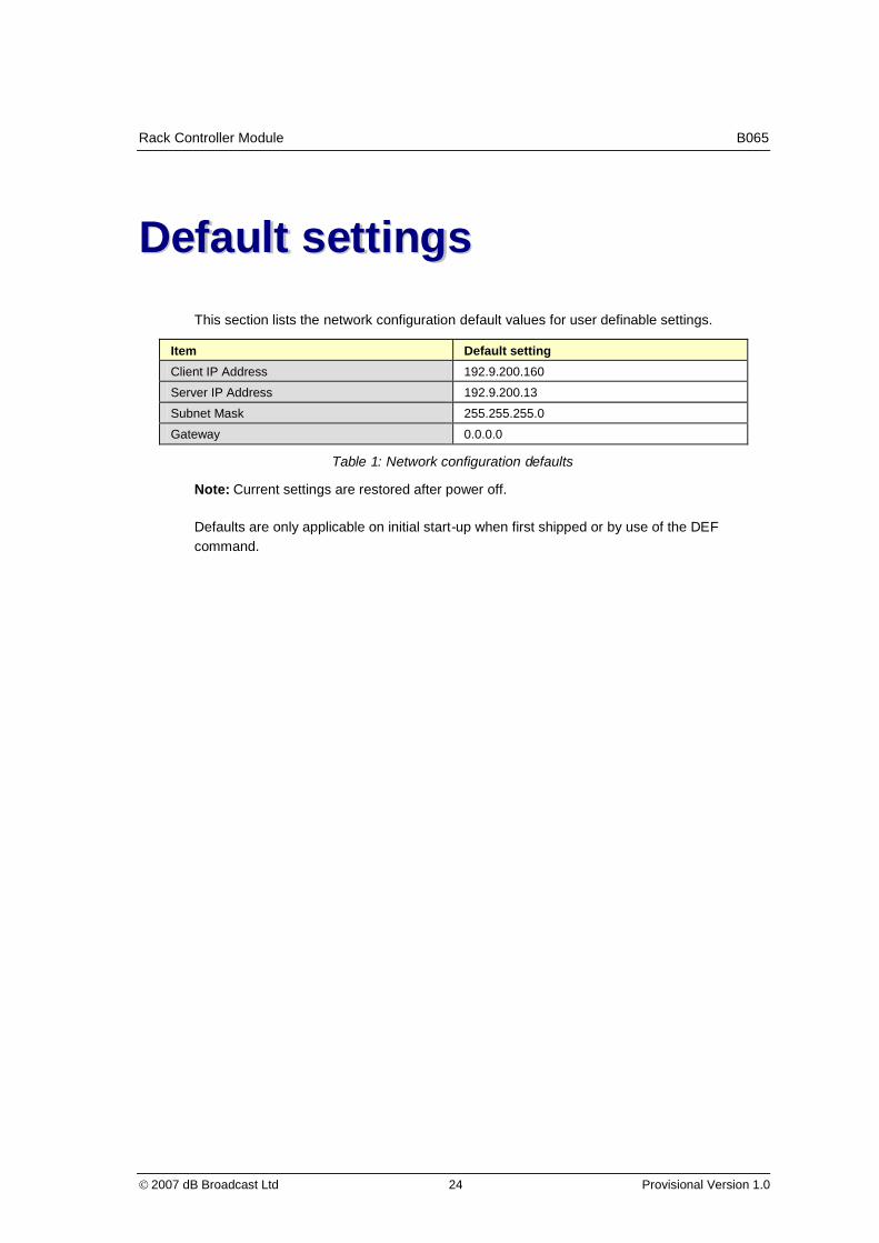
This section lists the network configuration default values for user definable settings.
Item Default setting
Client IP Address 192.9.200.160
Server IP Address 192.9.200.13
Subnet Mask 255.255.255.0
Gateway 0.0.0.0
Table 1: Network configuration defaults
Note: Current settings are restored after power off.
Defaults are only applicable on initial start-up when first shipped or by use of the DEF
command.

Rack Controller Module B065
2007 dB Broadcast Ltd 25 Provisional Version 1.0
UUppddaattiinngg ffiirrmmwwaarree
New software can be downloaded to the B065 using the following procedure:
In order to upgrade the application software, the B065 Control Card must first be placed in to
boot load mode. With a PC connected to the front panel local control port, run a standard
communications package (such as HyperTerminal) set to 38400 baud, 8 data bits, no parity,
1 stop bit, hardware handshaking enabled and enter the command DLOAD*. The following
messages will be displayed:
DLOAD*
*INFO: System Restart: Bootloader FW0779 Rev02
*INFO: Bootloader Forced, Application execution halted
Once boot load mode is activated then the application upgrade can be performed using
either the front panel local control port or the Ethernet port located on the rear panel. The
advantage of upgrading using the Ethernet connection is that the download is quicker but
requires use of a TFTP server. Serial download is slower but simpler to set-up (see the
following sections for details).
Note: Where available please use the TFTP (Ethernet) upload.
TFTP (Ethernet)
Upgrading the B065 Controller Card application software using TFTP (Ethernet) requires the
use of a TFTP server accessible through the network connection. Before starting the
upgrade, check and adjust network configuration settings.
A suitable free TFTP Server is available from the following SourceForge project:
http://sourceforge.net/projects/tftputil
It will be necessary to make this application point to the directory on the PC holding the
release application.
Once the network configuration settings have been checked, to upgrade the application
software enter the command DLTFTP <filename.S19>, where <filename.S19> is the
Motorola S-Record file containing the upgrade. For simplicity we have named the latest
version of the application APP.S19:
DLTFTP APP.S19
If the upgrade is successful the following messages will be displayed:
DLTFTP APP.S19
*INFO: FLASH Update in Progress

Rack Controller Module B065 Updating firmware
2007 dB Broadcast Ltd 26 Provisional Version 1.0
*INFO: Downloading S-Record 'APP.S19' from 192.9.200.13
*INFO: TFTP download successful
*INFO: Read 209118 bytes (409 blocks)
*INFO: Processing new Application Data...
*INFO: Erasing FLASH...
*INFO: Programming FLASH...
*INFO: FLASH programmed successfully - 26.7% used
Normally a download takes about 35 seconds from TFTP. If the download appears slow try
resetting the B065 (removing power) and try again; it's much faster.
RS232
Once boot load mode has been selected, to upgrade the B065 Controller Card application
software, transmit the Motorola S-Record file as a text file to the local control port. If the
upgrade is successful the following messages will be displayed:
*INFO: Processing new Application Data...
*INFO: Erasing FLASH...
*INFO: Programming FLASH...
*INFO: FLASH programmed successfully - 26.7% used
Starting the application
To start the application type:
RUNAPP
It is essential that the application is running to restore the module to normal operation.

Rack Controller Module B065
2007 dB Broadcast Ltd 27 Provisional Version 1.0
SSppeecciiffiiccaattiioonn
Ports
Front Panel RS232: Baud rate: 38400 Baud
Data bits: 8
Parity: none
Stop bit: 1
Flow control: RTS/CTS
Cable length: 15m (maximum)
Rear panel RS232: Baud rate: 38400, 19200, 9600
Data bits: 7,8
Parity: none, odd, even
Flow Control: none, RTS/CTS
Cable length: RS232; 15m (maximum), RS485;1000m (maximum).
GPI I/O: Input voltage: 5V max, Output current (sink):
10mA.
Status output contact: 0.5A@125V ac, 1A@30V dc.
Power
Input Voltage: 15VDC – provided by rack PSU(s)
Power Consumption: 4 W Maximum
Environmental
Temperature (Operating): 0 °C to +50 °C
Storing Temperature: -20 °C to +70 °C
Relative Humidity (maximumoperating):
80% for temperatures up to 31 °C, decreasinglinearly to 40% at 50 °C
Physical
Dimensions Height: 100 mm (4 inches)
Width: 25 mm (1 inch)
Depth: 265 mm (10.5 inches) (not including rear panel)
Net Weight: 0.35 kg (0.75 pounds)

Rack Controller Module B065 Specification
2007 dB Broadcast Ltd 28 Provisional Version 1.0
Safety standards
U.S. Nationally Recognised TestingLaboratory Listing:
UL3111-1, standard for electrical measuring andtest equipment
Canadian Certification: CAN/CSA 22.2 No. 1010.1
Safety requirements for electrical equipment formeasurement, control and laboratory use.
European Union Compliance: Low Voltage Directive 73/23/EEC, amended by
93/68/EEC
IEC 61010-1 Safety requirements for electrical
equipment for measurement, control andlaboratory use.
Safety certification
Equipment Type: Test and Measuring
Safety Class: Class I (as defined in IEC 61010-1, Annex H) –
grounded product
Over voltage Category: Over voltage Category II (as defined in IEC 61010-1, Annex J)
Pollution Degree: Pollution Degree 2 (as defined in IEC 61010-1)
Note: Rated for indoor use only
EC Declaration of Conformity – EMC: Meets intent of Directive 89/336/EEC and 92/3EEC
for Electromagnetic Compatibility. Compliance was demonstrated to the followingspecifications as listed in the Official Journal of the European Communities:
EC Declaration of Conformity – Low Voltage: Compliance was demonstrated to the
following specification as listed in the Official Journal of the European Communities:
Low Voltage Directive 73/23/EEC, amended by 93/68/EEC IEC 61010-1
Safety requirements for electrical equipment for measurement, control and laboratory use
EN50081-1 Emissions:1
BS EN55022: Class B radiated and conducted emissions
BS EN55013: Emissions standard for Broadcast Equipment
EN50082-1 Immunity: 1
BS EN61000-4-2: ESD Requirements
BS EN61000-4-3: Radiated susceptibility
BS EN61000-4-4: Electrical Fast Transient Burst requirement
BS EN61000-4-5: Surges requirement
BS EN61000-4-6: Conducted susceptibility
BS EN61000-4-11: Voltage Dips and Interruptions
BS EN55103-2: Immunity for Product Family Standard, Audio,Video Audio Visual and Entertainment lighting
control apparatus for professional use

Rack Controller Module B065 Specification
2007 dB Broadcast Ltd 29 Provisional Version 1.0
FCC Compliance: Emissions comply with FCC Code of Federal Regulations 47,
Part 15,Subpart B, Class A Limits1
FCC Information: This device complies with part 15 of the FCC Rules. Operation is
subject to the following two conditions: (1) This device may not cause harmfulinterference, and (2) this device must accept any interference received, including
interference that may cause undesired operation.
WARNING: The user must install the system as per manufacturers instructions, to complywith the requirements of FCC.
1Compliance demonstrated using high-quality, shielded cables.
Rack Controller Module B065
2007 dB Broadcast Ltd 30 Provisional Version 1.0
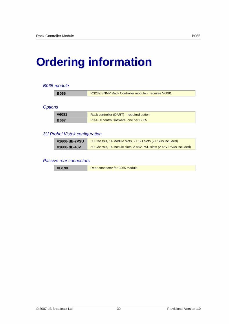
OOrrddeerriinngg iinnffoorrmmaattiioonn
B065 module
B065 RS232/SNMP Rack Controller module - requires V6081
Options
V6081 Rack controller (DART) – required option
B067 PC-GUI control software, one per B065
3U Probel Vistek configuration
V1606-dB-2PSU 3U Chassis, 14 Module slots, 2 PSU slots (2 PSUs included)
V1606-dB-48V 3U Chassis, 14 Module slots, 2 48V PSU slots (2 48V PSUs included)
Passive rear connectors
VB190 Rear connector for B065 module