autonomous waypoint-based guidance methods for … · acta polytechnica hungarica vol. 11, no. 10,...
TRANSCRIPT

Acta Polytechnica Hungarica Vol. 11, No. 10, 2014
– 215 –
Autonomous Waypoint-based Guidance
Methods for Small Size Unmanned Aerial
Vehicles
Dániel Stojcsics
Óbuda University, John von Neumann Faculty of Informatics, Budapest, Hungary
Abstract: The AERObot is a special ARM microcontroller-based autopilot for small and
medium size UAVs1 developed at Óbuda Universtiy for research purposes. The aim of the
research was to create a generic autopilot which is capable of controlling different design,
weight and structure airframes without any complex parameter or model recalculation as
usual for e.g. switching between tailless or classic tail aircafts. For this purpose a simple,
desired heading-based guidance method was developed which is easy to visualize and
needs only a few parameters to be set while the quality remains the same as the existing
ones. The paper presents a new guidance method and a few example controller types which
can fit it. Test flights were made to demonstrate the real time opeartion and low compution
needs of the presented methods.
Keywords: Unmanned Aerial Vehicle; UAV; Guidance; Navigation; Fuzzy; Mamdani
Controller; Nonlinear Controller
1 Introduction
Most of the UAV autopilots are based on a complex mathematical model using
differential equations of motion. These approaches are perfect for most controller
types such as classical control [1, 2, 3, 4, 5], state-space methods [6], optimal or
robust control [7] and even for fuzzy control [8, 9] system. The problem with
those approaches are their strong model based behaviour. These systems are
sensitive of the model changes e.g. electric to glow engine conversation or
different airframe structures (classic or tailless). With this approach a specific
autopilot cannot control these airframes without strong modification of the used
model reference and control system approach.
1 Unmanned Aerial Vehicle

D. Stojcsics Autonomous Waypoint-based Guidance Methods for Small Size Unmanned Aerial Vehicles
– 216 –
Instead of the previous approach AERObot is using and RC2 based solution even
with multiple navigation and control methods. Most of the RC modellers are using
the same quasi-standard four basic channel based transmitter to control model
planes from small to large size (under 1 kg to 10+ kg). With these basic channels
(aileron, elevator, rudder and throttle) they can control the model in all three axes
(lateral, longitudinal and vertical) with proper thrust control. This approach is
independent from the plane structural design (easy driveable classic trainer, a
gentle glider, a special tailless plane or even a high speed jet). The main difference
of these is the inertia. The smaller plane is more agile. This behaviour is easy to
handle with the end point adjustment of the actuators (limiting the turn rates).
For the small size UAVs (under 10 kg) the structural deformations, aeroelastic
behaviour of the wing can be neglected since the used materials (fiberglass,
carbon parts as reinforcement or even complete composite structures) for the
airframe can handle more than 10 times more force than the larger, heavier ones
because of their tructural design and high strength to weight ratio [10].
With such an approach AERObot is capable of fully autonomous flight with real
time onboard guidance, navigation and control with a on-board ARM-based
embedded microcontroller unit. The core (STM32F103) is running at 72MHz
clock speed, capable of up to 90 MIPS only but it is lightweight which makes the
device ideal for small size aerial applications.
The current paper presents the complete simulation and real flight testing of the
created guidance method in order to demonstrate the real time application and
practical applicability of the system. The paper is structured as follows: section 2
presents the simulation possibilities. Sections 3 and 4 describe the estimations
needed for the guidacne presented in section 5. Then sections 6 and 7 presents the
simulated and real test flight results, summarized in the conclusions finally. The
extended version of the presented methods can be found on [11].
2 The HIL Simulation
The Aerosim blockset Matlab provides a complete solution for guidance,
navigation and control az unmanned aerial vehicle under Matlab. A general 6 DoF
nonlinear UAV model with all the equations of motion is provided in the blockset
for further research, e.g. custom UAV identification [12].
The 6 DoF system is using an atmosphere and earth model for the computation of
the aerodynamics, propulsion, and inertia model, used for the equations of motion
(Fig. 1), fully described in [13], calculating the momentum, acceleration,
orientation, position etc of the unmanned aircraft. The HIL simulation is able to
2 Radio Control

Acta Polytechnica Hungarica Vol. 11, No. 10, 2014
– 217 –
create the same environment as the real flight. The autopilot is acting the same as
real; it has no information about the source of the measured signals which are
generated with PC simulation software. A mathematical model created in
Matlab/Simulink (Fig. 2) processes the states of the UAV using the actuator
signals captured from the autopilot [14]. The autopilot is using the simulated
signals instead of its own internal sensors for the filter, navigation and control
algorithms. The simulator sends the output of the simulation (position, orientation,
airspeed and altitude etc.) to the autopilot via serial port with a desired control
frequency (e.g. 100 Hz) which is the same as the update frequency of the control
functions (discrete time simulation with a real time model). The autopilot is not
using its internal timer but the timestamp from the simulator.
Figure 1
6-DoF unmanned aircraft dynamics system: Aerosim
Figure 2
Matlab HIL model using Simulink and AeroSim blockset with serial i/o

D. Stojcsics Autonomous Waypoint-based Guidance Methods for Small Size Unmanned Aerial Vehicles
– 218 –
The generic small size fixed wing UAV model was created in Matlab/Simulink
using the AeroSim block set using a predefined UAV 6 DoF3 model for the
validation purposes of the HIL simulation [14]. A lot of conclusion and test data
are available for the control functions and navigation from real flights in the past
[11], so the simulated results could be compared to real measured ones. The
selected block set has an interface to FlightGear flight simulator so the HIL test
flights can be observed in such a graphical way. The simulated outputs can be
ideal or noisy (generated). Using ideal values the internal filters can be bypassed.
Otherwise the HIL simulation is capable of testing the onboard software filters in
different situations. The autopilot calculates and sends back the actuator signals
based on the received values while also refreshing the physical actuator. These
signals are the inputs of the simulation model.
3 Bearing Estimation
The base sensor for the navigation is the GPS4. It provides the position, SOG
5,
bearing and many other parameters used by the navigation algorithms. The
maximum position refresh rate of best GPS modules is about 5-10 Hz, which is
not enough for precision flight control.
The other problem is that the refresh rate is not reliable because NMEA6 sentences
and the checksums are often incorrect. It is necessary to estimate the missing, and
intermediate positions for the continuous bearing control (100 Hz – update
frequency of the most actuators). This estimation can be computed using the
vertical angular velocity and the GPS bearing from the last valid NMEA sentence.
The actual bearing can be estimated between two valid GPS sentences (1), fully
described in [11]. The heading angle provided by the IMU is often not reliable,
because of the magnetic sensor used by the internal sensor fusion algorithms. This
sensor is very sensitive to strong electromagnetic fields especially when the UAV
has electric propulsion.
𝜃𝑒 = 𝜃 + �̇�𝑡𝑠 (1)
where:
θ: previous bearing (measured by GPS)
θe: estimated bearing
�̇�: angular velocity
𝑡𝑠: sample time
3 Degrees of freedom
4 Global Positioning System
5 Speed over ground
6 National Marine Educators Association – Predefined sentence types used by GPS
modules
Acta Polytechnica Hungarica Vol. 11, No. 10, 2014
– 219 –
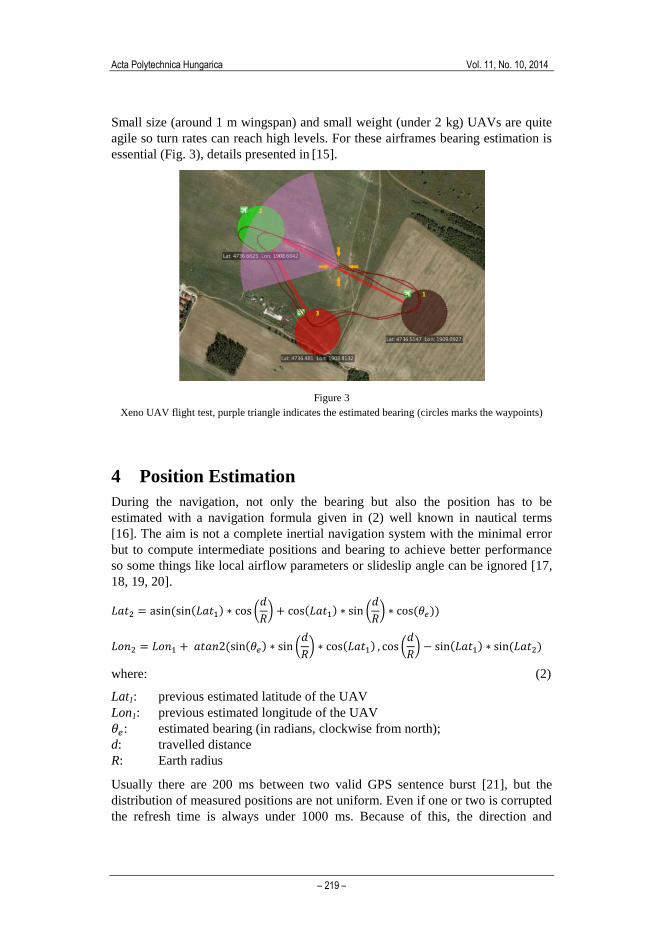
Small size (around 1 m wingspan) and small weight (under 2 kg) UAVs are quite
agile so turn rates can reach high levels. For these airframes bearing estimation is
essential (Fig. 3), details presented in [15].
Figure 3
Xeno UAV flight test, purple triangle indicates the estimated bearing (circles marks the waypoints)
4 Position Estimation
During the navigation, not only the bearing but also the position has to be
estimated with a navigation formula given in (2) well known in nautical terms
[16]. The aim is not a complete inertial navigation system with the minimal error
but to compute intermediate positions and bearing to achieve better performance
so some things like local airflow parameters or slideslip angle can be ignored [17,
18, 19, 20].
𝐿𝑎𝑡2 = asin(sin(𝐿𝑎𝑡1) ∗ cos (𝑑
𝑅) + cos(𝐿𝑎𝑡1) ∗ sin (
𝑑
𝑅) ∗ cos(𝜃𝑒))
𝐿𝑜𝑛2 = 𝐿𝑜𝑛1 + 𝑎𝑡𝑎𝑛2(sin(𝜃𝑒) ∗ sin (𝑑
𝑅) ∗ cos(𝐿𝑎𝑡1) , cos (
𝑑
𝑅) − sin(𝐿𝑎𝑡1) ∗ sin (𝐿𝑎𝑡2)
where: (2)
Lat1: previous estimated latitude of the UAV
Lon1: previous estimated longitude of the UAV
𝜃𝑒: estimated bearing (in radians, clockwise from north);
d: travelled distance
R: Earth radius
Usually there are 200 ms between two valid GPS sentence burst [21], but the
distribution of measured positions are not uniform. Even if one or two is corrupted
the refresh time is always under 1000 ms. Because of this, the direction and

D. Stojcsics Autonomous Waypoint-based Guidance Methods for Small Size Unmanned Aerial Vehicles
– 220 –
velocity of the wind can be ignored. During the estimation the last known SOG
can be used no matter how the bearing of the UAV changed (compared to the
wind). Obviously there will be some estimation errors, but usually it is low (under
1 m) and not causing any serious false position estimation [15].
The estimation (Fig. 4) can be calculated from the previous known SOG,
estimated position and bearing (when known position and bearing are not
available) [11].
Figure 4
Position estimation simulation from telemetry data
(downsampled, big dots are the measured, small dots are the estimated positions)
Longitude
Lat
itu
de
Acta Polytechnica Hungarica Vol. 11, No. 10, 2014
– 221 –
5 Guidance
There are many guidance approaches. Most of them are using waypoints [22],
defined by a geographic position (latitude and longitude), an altitude (AGL7 or
ASL8) and a waypoint radius (usually 25-75 m, used to achieve precise path
tracking). A waypoint is reached, when the distance between the UAV and the
waypoint is under the predefined radius value.
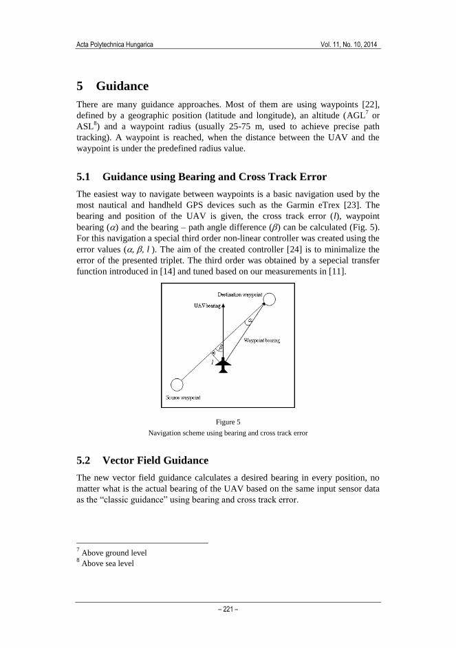
5.1 Guidance using Bearing and Cross Track Error
The easiest way to navigate between waypoints is a basic navigation used by the
most nautical and handheld GPS devices such as the Garmin eTrex [23]. The
bearing and position of the UAV is given, the cross track error (l), waypoint
bearing () and the bearing – path angle difference () can be calculated (Fig. 5).
For this navigation a special third order non-linear controller was created using the
error values (l). The aim of the created controller [24] is to minimalize the
error of the presented triplet. The third order was obtained by a sepecial transfer
function introduced in [14] and tuned based on our measurements in [11].
Figure 5
Navigation scheme using bearing and cross track error
5.2 Vector Field Guidance
The new vector field guidance calculates a desired bearing in every position, no
matter what is the actual bearing of the UAV based on the same input sensor data
as the “classic guidance” using bearing and cross track error.
7 Above ground level
8 Above sea level
D. Stojcsics Autonomous Waypoint-based Guidance Methods for Small Size Unmanned Aerial Vehicles
– 222 –
This can be easily represented as a vector field. The desired bearing depends on
the position of the UAV, source and destination waypoints and the cross track
error [11]:
𝛿 = √|𝐷𝐶𝑇 ∗ 𝐾𝑐 ∗ (𝜑𝑇 − 𝜑𝑅)|𝐾𝑑
∗ 𝑠𝑖𝑔𝑛(𝐷𝐶𝑇)
𝛾 = 𝑚𝑖𝑛(1, 𝐷𝑇)
𝜑𝑑 = 𝜑𝑇 + 𝛿 ∗ 𝛾 (3)
where:
DCT: Cross track error,
𝐷𝑇: Distance from target
𝜑𝑑: Desired bearing,
𝜑𝑇: Bearing from the UAV to the destination waypoint,
𝜑𝑅: Bearing from the previous to the destination waypoint,
Kd: Path reaching gain,
Kc: Cross track error gain,
𝛾: Waypoint bearing gain.
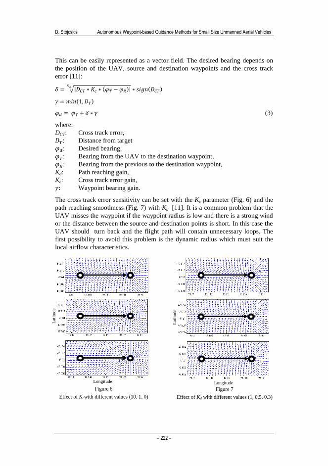
The cross track error sensitivity can be set with the Kc parameter (Fig. 6) and the
path reaching smoothness (Fig. 7) with Kd [11]. It is a common problem that the
UAV misses the waypoint if the waypoint radius is low and there is a strong wind
or the distance between the source and destination points is short. In this case the
UAV should turn back and the flight path will contain unnecessary loops. The
first possibility to avoid this problem is the dynamic radius which must suit the
local airflow characteristics.
Figure 6
Effect of Kcwith different values (10, 1, 0)
Figure 7
Effect of Kd with different values (1, 0.5, 0.3)
Longitude
Lat
itude
Longitude
Lat
itude

Acta Polytechnica Hungarica Vol. 11, No. 10, 2014
– 223 –
The other, and better solution is the usage of 𝛾. If the UAV is close to the
destination point (under 1000m) the parameter 𝛾 guarantees the reach of the
waypoint, ignoring 𝛿 that depends on the UAV – waypoint distance (Fig. 8). This
solution was realized by our approach [11].
The first advantage of this navigation is the easy graphical setup of the internal
parameters Kc (~10.0) and Kd (~0.5). The other is that it has only one output
parameter (𝜑𝑑) so nearly any controller type (such as third order non-linear, PID,
fuzzy etc.) can fit this navigation because only one value, the difference of desired
and actual bearing should be minimized. Furthermore, with a little modification
based on (4) [11] it is capable of loiter navigation over a desired position (Fig. 9).
𝜑𝑑 = 𝜑𝑇 + 𝜋
2+ 𝑚𝑖𝑛 (|𝐷𝐶𝑇 ∗ 𝐾𝑐|,
𝜋
2) ∗ 𝑠𝑖𝑔𝑛(𝐷𝐶𝑇) (4)
where:
𝐷𝐶𝑇: Cross track error (distance from the radius),
𝜑𝑑: Desired bearing,
𝜑𝑇: Bearing from the UAV to the destination waypoint,
Kc: Cross track error gain.
Figure 8
Effect of 𝛾 with different values
(0, 1, 𝑚𝑖𝑛(1, 𝐷𝑇))
Figure 9
Loiter navigation
Longitude
Lat
itu
de
Longitude
Lat
itu
de

D. Stojcsics Autonomous Waypoint-based Guidance Methods for Small Size Unmanned Aerial Vehicles
– 224 –
6 Controller
There are many things to consider during the selection of an appropriate controller
for the UAV. The classic PID controller has many benefits, several autopilots are
using it [25, 26, 27, 28]. The setup process of these autopilots is pretty difficult or
they can be used with strong limitations, due to the non-linear aircraft
characteristics [4, 5].
6.1 Third Order Non-Linear Controller
At least three controller channels and a few compensators are needed to control an
unmanned airplane and achieve the appropriate flight characteristics. The basic
controller channels are the airspeed, altitude and bearing (guidance) [29, 30, 31].
The implementation can be different based on the available flight data. The
AERObot autopilot controls the altitude with the engine throttle and the airspeed
with the elevator. In case of electric propulsion (continuously decreasing
performance because of the electric battery characteristics), this implementation
provides adequate airspeed control.
Figure 10
Transfer diagram of the third order non-linear controller
A special non-linear third order controller [32] function has been applied to the
AERObot autopilot. The advantage of this is the capability to control non-linear
systems like UAVs without linearization. Furthermore several years of practical
experience are available for this kind of controller. The transfer functions used in
-255
0
255
0 100 200 300
Co
ntr
ol sig
na
l
Altitude [m]
desired altitude
Z0
min
max 100
-100

Acta Polytechnica Hungarica Vol. 11, No. 10, 2014
– 225 –
the controllers can be interpreted as seen on Fig. 10. The target value (i.e. Xc=150
m - altitude controller) and the neutral output for that (Z0=0, trim condition) has
been marked. If the target altitude is higher than the current measured altitude, the
output will be higher than the neutral value. If the target altitude is lower than the
current measured altitude, the output will be lower than the neutral value. The
function outputs must be limited between predefined values (e.g. ±100) for
practical use. This control method can be used for control surfaces with
symmetrical deflection, e.g. the rudder, aileron, elevator or the engine (both
electric and glow) throttle. The central “flat” part of the function should be the
trim output value (Z0) e.g. the throttle control signal at level flight. This controller
is capable of controlling the airspeed, altitude directly and with a little
modification it is also suitable for navigation. The navigation controller (5) using
the calculated values (, , l) gives the control signal (Kh) which drives directly
the rudder (and ailerons) [29].
Detailed analysis was made before the flight test to examine the effect of
navigation parameters. Neglecting path tracking sensitivity (h1 = 0) results only
the reach of target waypoint but with major cross track error. Increasing this
parameter, proper path tracking can be achieved with minimal cross track error.
3
210
3210
3210
)*)*)90(**)(((
min,min,)*)*)90(**)(((
max,max,)*)*)90(**)(((
hhlhelse
thenhhlhif
thenhhlhif
Kh
(5)
where
Kh: control signal of the rudder (neutral = 0),
waypoint direction,
bearing – path angle difference,
l: cross track error,
h0: direction sensitivity parameter,
h1: path tracking sensitivity parameter,
h2: global sensitivity parameter (useful in the real flight tests).
6.2 Fuzzy Control
The fuzzy control box was created with the Matlab fuzzy toolbox using Mamdani-
type controller. The inputs of the controller box are the same as in the third order
controller (target speed, target altitude, actual airspeed, actual altitude, bank angle,
pitch angle, heading error). The outputs are the same too (control surface
deflection and engine throttle commands).
The fuzzy controller box contains five simple fuzzy controller channels and two
linear compensators [33]. There are two stabilization channels (bank and pitch
angle) in addition to the three classic controllers (airspeed, altitude, heading). In
the case of the third order controller, they were embedded into the three classic

D. Stojcsics Autonomous Waypoint-based Guidance Methods for Small Size Unmanned Aerial Vehicles
– 226 –
channels. Every controller is a simple Mamdani controller with two (bank angle,
pitch angle, heading) or three (airspeed, altitude) triangular input and output
membership functions (Fig. 11, 12) with centroid defuzzyfication method [34].
Figure 11
Visual representation of the three triangular input and output membership functions (airspeed
controller)
Figure 12
The transfer diagrams of the Mamdani controllers with two (airspeed) and three (altitude) membership
functions
In some cases, non-linear compensators must be used which correlates with
airspeed or bank angle. Using both pitch and bank angle controllers there is no
need for this. The rudder – aileron compensator is needed for the precise
navigation. Without this the UAV cannot perform banked turns. The turn radius
can be way more than 100 meters instead of the desired 10-20 meters (Fig. 13).
The proper value can be specified with HIL simulation flight tests (Fig. 14, 15).
7 Test Flights
Many test flights has been made with different size and weight UAVs during the
years to test the navigation and the control methods. Test UAVs were based on
classic and tailless airframes with both electric and glow propulsion. All the real
flights were made after many hours of HIL simulation tests.

Acta Polytechnica Hungarica Vol. 11, No. 10, 2014
– 227 –
Figure 13
Effect of rudder – aileron compensator with different parameters on the flight route with three
waypoints - waypoints marked with circles
Figure 14
UAV roll and pitch angle plot of two turns
(blue: fuzzy, red: third order)
Figure 15
Airspeed and altitude plot of two turns
(blue: fuzzy, red: third order)

D. Stojcsics Autonomous Waypoint-based Guidance Methods for Small Size Unmanned Aerial Vehicles
– 228 –
7.1 Tiger 60 UAV
The Tiger 60 is a 1.7 m wingspan UAV with classic acrobatic trainer airframe
with a 10 cm3 internal combustion engine [35]. The mass of the plane is 4kg with
AERObot autopilot, additional electronics and fuel. It has a built in XBee Pro 2.4
GHz modem for real time telemetry for commands and monitoring flight
parameters.
The plane has third order non-linear controllers with bearing and cross track error
navigation. The AERObot is capable of manual, autonomous and heterogenous
flight. The take-off and landing was made in manual mode, the waypoint flight in
autonomous (Fig. 16).
Figure 16
Tiger 60 UAV test flight in a three waypoint continuous route (waypoints marked with circles)
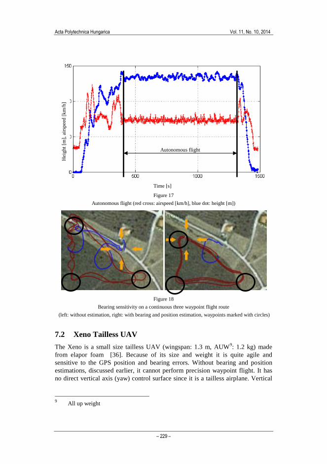
The desired airspeed was 90 km/h and the altitude is 150 m AGL. The routeplan
was continous and contained three waypoint. During the test flight there was a
moderate wind which had little influence on the flight path. Both airspeed and
altimeter controller had a small offset error (Fig. 17) since the controller has no
integrator part.
wind direction
Acta Polytechnica Hungarica Vol. 11, No. 10, 2014
– 229 –
Figure 17
Autonomous flight (red cross: airspeed [km/h], blue dot: height [m])
Figure 18
Bearing sensitivity on a continuous three waypoint flight route
(left: without estimation, right: with bearing and position estimation, waypoints marked with circles)
7.2 Xeno Tailless UAV
The Xeno is a small size tailless UAV (wingspan: 1.3 m, AUW9: 1.2 kg) made
from elapor foam [36]. Because of its size and weight it is quite agile and
sensitive to the GPS position and bearing errors. Without bearing and position
estimations, discussed earlier, it cannot perform precision waypoint flight. It has
no direct vertical axis (yaw) control surface since it is a tailless airplane. Vertical
9 All up weight
Autonomous flight
Time [s]
Hei
ght
[m],
air
spee
d [
km
/h]

D. Stojcsics Autonomous Waypoint-based Guidance Methods for Small Size Unmanned Aerial Vehicles
– 230 –
axis movements are replaced with longitudinal axis banked turns making the UAV
much more sensitive to bearing control than the bigger Tiger 60. The bearing and
position estimation algorithms were tested successfully (Fig. 18). The used
navigation for this UAV was the previously discussed vector field navigation with
PID and Fuzzy controllers.
Conclusions
The discussed vector field navigation method with bearing and position estimation
is suitable for any generic autopilot for small size UAVs. As the HIL simulation
and the test flights have shown the AERObot with the discussed methods are
capable of controlling different design, weight and structure airframes without any
complex mathematical model recalculation unlike the other strongly model based
autopilots. It has no major sensitivity for the airframe structure, propulsion or any
other main dominant factor.
The system has an easy setup interface where the user can set the UAV type,
actuator idle and end points as well as the controller gains, like in the case of an
RC model and its generic RC transmitter.
AERObot can control not only conventional fixed wing planes but agile special
tailless flying wings with low radar cross-section. This feature makes it an ideal
platform to develop new navigational, control or stabilizer methods.
As a result a low compution time guidance method was created and successfully
tested with multiple on-board real time controller types. Test fligts have promising
results. Further research is needed for precision guidance and optimal control
strategies to achieve low energy consumption and longer flight times.
References
[1] Y. Shengyi, L. Kunqin, S. Jiao: Optimal Tuning Method of PID Controller
Based on Gain Margin and Phase Margin, International Conference on
Computational Intelligence and Security, 2009, pp. 634-638, ISBN: 978-1-
4244-5411-2
[2] V. Kargin: Design of an Autonomous Landing Control Algorithm for a
Fixed Wing UAV, MS Thesis, Middle East Technical University, Ankara,
Turkey, 2007
[3] J. Amahah: The Design of an Unmanned Aerial Vehicle Based on the
ArduPilot, Georgian Electronic Scientific Journal: Computer Science and
Telecommunications, 2009, No. 5 (22), pp. 144-153
[4] Cho et al.: Fully Automatic Taxiing, Takeoff and Landing of a UAV using
a Single-Antenna GPS Receiver only, International Conference on Control,
Automation and Systems 2007, Oct. 17-20, 2007 in COEX, Seoul, Korea,
ISBN: 978-89-950038-6-2, pp. 821-825

Acta Polytechnica Hungarica Vol. 11, No. 10, 2014
– 231 –
[5] H. Chao, Y. Luo, L. Di and Y. Chen: "Fractional Order Ight Control of
Small Fixedwing UAV: Controller Design and Simulation Study",
Proceedings of the ASME 2009 International Design Engineering
Technical Conferences and Computers and Information in Engineering
Conference, 2009, pp. 621-628, ISBN: 978-0-7918-4900-2
[6] V. V. Patel et al: L1 Adaptive Controller for Tailless Unstable Aircraft,
Proceedings of the 2007 American Control Conference, 2007, ISBN: 1-
4244-0988-8, pp. 5272-5277
[7] W. Rui, Z. Zhou and S. Yanhang: Robust Landing Control and Simulation
for Flying Wing UAV, Proceedings of the 26th
Chinese Control
Conference, July 26-31, 2007, Zhangjiajie, Hunan, China, ISBN: 978-7-
81124-055-9, pp. 600-604
[8] K. Bickraj, T. Pamphile, A. Yenilmez, M. Li, I. N. Tansel: Fuzzy Logic
Based Integrated Controller for Unmanned Aerial Vehicles, Florida
Conference on Recent Advances in Robotics, FCRAR 2006
[9] S. Kurnaz, O. Çetin: Autonomous Navigation and Landing Tasks for Fixed
Wing Small Unmanned Aerial Vehicles, Acta Polytechnica Hungarica Vol.
7, No. 1, 2010, pp. 87-102
[10] D. Cadogan, W. Graham, T. Smith: Inflatable and rigidizable wings for
unmanned aerial vehicles, 2nd
AIAA "Unmanned Unlimited" Systems,
Technologies, and Operations, 2003, California, USA
[11] D. Stojcsics, A. Molnár: AirGuardian – UAV Hardware and Software
System for Small Size UAVs, International Journal of Advanced Robotic
Systems, 2012, Croatia, ISSN 1729-8806, DOI: 10.5772/52759, Vol. 9,
174:2012, pp. 1-8
[12] Y. C. Paw, G. J. Balas: Parametric Uncertainty Modeling for LFT Model
Realization, 2008 IEEE Int Symposium on Computer-aided Control
System Design,USA, September 3-5, 2008
[13] "AeroSim Blockset User's Guide", Unmanned Dynamics LCC, USA, 2004
[14] A. Molnár, D. Stojcsics: HIL szimuláció a robotpilóta fejlesztésben,
Repüléstudományi Konferencia, Repüléstudományi közlemények
különszám, 2011, Szolnok
[15] D. Stojcsics: Flight Safety Improvements for Small Size Unmanned Aerial
Vehicles, IEEE 16th
International Conference on Intelligent Engineering
Systems 2012, Lisbon, Portugal, ISBN: 978-1-4673-2693-3 (pendrive);
978-1-4673-2692-6 (printed), pp. 483-487
[16] F. Ucan, D.T. Altilar: Navigation and Guidance Planning for Air Vehicles,
20th
IEEE International Conference on Tools with Artificial Intelligence,
ICTAI 2008, Vol. 2, No., pp. 534-538

D. Stojcsics Autonomous Waypoint-based Guidance Methods for Small Size Unmanned Aerial Vehicles
– 232 –
[17] Q. Li, Z. Fang, H. Li: The Application of Integrated GPS and Dead
Reckoning Positioning in Automotive Intelligent Navigation System,
Journal of Global Positioning Systems (2004) Vol. 3, No. 1-2: 183-190
[18] P. Davidson, J. Hautamäki, J. Collin: Using Low-Cost MEMS 3D
Accelerometers and One Gyro to Assist GPS-based Car Navigation
System, Proceedings of 15th
Saint Petersburg International Conference on
Integrated Navigation Systems, May 2008
[19] L. Zhao, W. Y. Ochieng, M. A. Quddus and R. B. Noland: An Extended
Kalman Filter Algorithm for Integrating GPS and Low-Cost Dead
Reckoning System Data for Vehicle Performance and Emissions
Monitoring, Journal of Navigation, 2003, 56: 257-275
[20] S. Leven, J. Zufferey, and D. Floreano: A Minimalist Control Strategy for
Small UAVs, in Proc. IROS, 2009, pp. 2873-2878
[21] F. Rovira-Más, R. Banerjee: GPS Data Conditioning for Enhancing
Reliability of Automated Off-Road Vehicles. Proceedings of the Institution
of Mechanical Engineers, Part D: Journal of Automobile Engineering,
2013, 227(4), 521-535
[22] R. Beard et al: Autonomous Vehicle Technologies for Small Fixed-Wing
UAVs, Journal Of Aerospace Computing Information and Communication
(2005) Volume: 2, Issue: 1, pp. 92-108, ISSN: 19403151
[23] B. Xiao, K. Zhang, R. Grenfell, T. Norton: Handheld GPS – Today and
Tomorrow, FIG XXII International Congress Washington, D.C. USA,
April 19-26 2002
[24] A. Molnár, D. Stojcsics: New Approach of the Navigation Control of Small
Size UAVs, Proceedings of 19th
International Workshop on Robotics in
Alpe-Adria-Danube Region, ISBN: 978-1-4244-6884-3, Budapest,
Hungary, 2010, pp. 125-129
[25] K. Turkoglu, U. Ozdemir, M. Nikbay, E. M. Jafarov: "PID Parameter
Optimization of an UAV Longitudinal Flight Control System", WCSET
2008 World Congress on Science, Engineering and Technology, ICCARV
2008 International Conference on Control, Automation, Robotics and
Vision, 21-23 November 2008, Laval, France
[26] S. J. Jung, D. Liccardo: Small UAV automation using MEMS, 2007, IEEE
Aerospace and Electronic Systems Magazine, Vol. 22, No. 5, pp. 30-34
[27] A. L. Salih, M. Moghavvemi, H. A. F. Mohamed, K. S. Gaeid: Flight PID
Controller Design for a UAV Quadrotor, 2010, Scientific Research and
Essays, Vol. 5, No. 23, pp. 3660-3667
[28] P. E. I. Pounds, D. R. Bersak, A. M. Dollar: Stability of Small-Scale UAV
Helicopters and Quadrotors with Added Payload Mass under PID Control,
2012, Autonomous Robots, Vol. 33, No. 1-2, pp. 129-142

Acta Polytechnica Hungarica Vol. 11, No. 10, 2014
– 233 –
[29] D. Stojcsics, A. Molnar: Fixed-Wing Small-Size UAV Navigation Methods
with HIL Simulation for AERObot Autopilot, Proc. of 9th
International
Symposium on Intelligent Systems and Informatics, Subotica, Serbia,
September 8-10, 2011, ISBN: 978-1-4577-1974-5
[30] A. Cho et al.: Fully Automatic Taxiing, Takeoff and Landing of a UAV
using a Single-Antenna GPS Receiver Only, 2007, ICCAS - International
Conference on Control, Automation and Systems, p. 821
[31] B. M. Albaker, N. A. Rahim: Flight Path PID Controller for Propeller-
driven Fixed-Wing Unmanned Aerial Vehicles, 2011, International Journal
of Physical Sciences, Vol. 6, No. 8, pp. 1947-1964
[32] A. Molnár: A polgári és katonai robotjárművek fejlesztésében alkalmazott
új eljárások és technikai megoldások”, PhD dissertation, 2006, Zrínyi
Miklós Nemzetvédelmi Egyetem, Budapest
[33] D. Stojcsics: Fuzzy Controller for Small Size Unmanned Aerial Vehicles,
10th
Jubilee International Symposium on Applied Machine Intelligence and
Informatics, ISBN: 978-1-4577-0195-5, Herl'any, Slovakia, January 26-28,
2012
[34] K. M. Passino, S. Yurkovich: Fuzzy Control, Addison Wesley Longman,
1998
[35] Phoenix Modell: Tiger 60 Instruction manual, Vietnam
[36] Multiplex Gmbh: Xeno building instructions, Germany, 2009