automatic trumpet tuner
TRANSCRIPT

AUTOMATIC TRUMPET TUNER
By
Tyler Baldassone
James Lithgow
Lowie Rodriguez
Final Report for ECE 445, Senior Design, Spring 2018
TA: Jacob Bryan
02 May 2018
Project No. 06

ii
Abstract
Our project is an Automatic Trumpet Tuner. Our design attaches itself to any trumpet, and reacts to the trumpet’s audio input, autonomously moving the tuning slide to get the trumpet in tune. Utilizing a linear actuator, a microphone circuit, and a microcontroller, we were able to create a functional design that succeeds in recognizing the input pitch, comparing it to the appropriate ‘in tune’ frequency, and adjusting the trumpet’s tuning slide accordingly. Within this report is the reasonings behind our design decisions, and the tests that proved that our system is functional.

iii
Contents
1. Introduction .......................................................................................................................................... 1
1.1 Objective ....................................................................................................................................... 1
1.2 Background ................................................................................................................................... 1
1.3 High-level requirements ............................................................................................................... 2
1.4 Frequency to cents: a crossover between music and electrical engineering ............................... 2
2. Design .................................................................................................................................................... 4
2.1 Functional Overview ..................................................................................................................... 4
2.2 Physical Design .............................................................................................................................. 4
2.3 Audio Unit ..................................................................................................................................... 4
2.3.1 MEMS Microphone ............................................................................................................... 5
2.3.2 Low Pass Filter ....................................................................................................................... 5
2.3.3 Amplifier Circuit .................................................................................................................... 6
2.3.4 Analog to Digital Converter ................................................................................................... 6
2.4 Processing Unit ............................................................................................................................. 7
2.4.1 Microcontroller ..................................................................................................................... 7
2.4.2 Status LEDs ............................................................................................................................ 8
2.5 Power Unit .................................................................................................................................... 8
2.5.1 Battery/DC Power ................................................................................................................. 8
2.5.2 On-Off Switch ...................................................................................................................... 10
2.5.3 Voltage Regulator/DC-DC Converter .................................................................................. 10
2.6 Mechanical Unit .......................................................................................................................... 11
2.6.1 H-Bridge .............................................................................................................................. 11
2.6.2 Linear Actuator ................................................................................................................... 11
3. Costs .................................................................................................................................................... 12
3.1 Parts ............................................................................................................................................ 12
3.2 Labor ........................................................................................................................................... 12
4. Conclusion ........................................................................................................................................... 13
4.1 Accomplishments ........................................................................................................................ 13
4.2 Ethics ........................................................................................................................................... 13

iv
4.3 Safety .......................................................................................................................................... 13
4.4 Future work ................................................................................................................................. 13
Appendix A Requirement and Verification Table ................................................................................... 15
Appendix B Tables and Figures ............................................................................................................... 19
References .................................................................................................................................................. 32

1
1. Introduction
1.1 Objective A large problem in any musician’s life is tuning. The tuning of an instrument changes constantly based
on the temperature of the room and the instrument, the changing embouchure (placement of the lips
on the instrument) the musician uses, and on every note played. While an experienced musician can
account for this most of the time, a beginner or intermediate player will still have trouble consistently
staying in tune. This can be detrimental at times, especially on longer notes where you can tell whether
one member of a band is out of tune or not. The trumpet section is often the largest section of any
band, and because of this each trumpet player needs to pay close attention to tuning with all the other
players.
Our proposed solution is to create an automatic tuner (auto-tuner) that can be placed on the trumpet
and will adjust the tuning. The auto-tuner will be battery powered so that the musician may move
around freely, but also have a DC source that will allow for longer sessions of playing with the auto-
tuner. The auto-tuner will listen to the player’s trumpet and perform frequency prediction to show the
player whether they are sharp, flat, or in-tune. At this point, the player has to do nothing but play
normally, as the auto-tuner moves the tuning slide in or out depending on the frequency prediction
done. We predict this solution to be a low to medium cost solution, while still striving for a quality
product that will accurately tune the trumpet.
The results of this project were largely successful. A majority of the requirements were passed in the
first prototype, and the main issue arose in the mechanical application due to inexperience in this area
of design. Had there been time for a second version prototype, we are confident that all flaws would be
resolved, with a clear direction for future improvements in both the hardware and software of this
design.
1.2 Background A trumpet’s intonation, how in-tune a note is, consistently changes during a practice session. The
intonation is so prone to changing due to many factors like temperature, experience, tendencies of
certain notes to be flat or sharp because of the physics of the instrument, among others [1]. In group
settings, like a band, multiple instruments are playing that all experience these intonation effects. The
result of even one instrument being out of tune is the creation of a beat frequency. This beat frequency
is equal to the difference of the tuning between the two instruments, and sounds like a fading and
approaching tone at a certain speed, which is undesirable. For more experienced players, they can
adjust their embouchure before the beat frequency becomes noticeable to the audience which makes
the music more pleasant. The question is how do musicians typically practice to get to this point?
The most common way to learn these tendencies of the trumpet is by sitting down with a chromatic
tuner, playing each note slowly, and recognizing when the instrument isn’t in tune so that you can adjust
your embouchure for the next time you play. This relies on spending a lot of time practicing, and being
able to hear the tone accurately and recalling it, called tonal memory or pitch memory [2]. While the use

2
of an auto-tuner will be beneficial for practicing the music itself, because the player will hear correct
pitches while playing music at a normal speed, and in group settings because musicians can focus on
blending with other players, it likely won’t completely negate the practice necessary to develop pitch
memory. An auto-tuner will enhance a musician's experience while practicing pitch memory though,
because instead of worrying about adjusting the slide or embouchure for every note, which is the only
method currently available to adjust tuning, they can continuously play while the auto-tuner provides
the necessary adjustments.
1.3 High-level requirements • The tuner shall automatically adjust the trumpet’s main tuning slide according to any chromatic
scale note within the trumpet’s range
• The tuner shall adjust the tuning of the trumpet to within 2 Hz of the desired note
• The tuner shall be able to run on battery power
• The tuner shall be able to run on a DC power source
1.4 Frequency to cents: a crossover between music and electrical
engineering In Electrical Engineering, frequency analysis is almost always done in hertz, while in Music, frequency
analysis is always done in terms of cents and note number, which corresponds to the note in the
chromatic scale used in all western music. Why this is the case is beyond the scope of this paper,
however it is important to realize the mathematical relationship between the two, and how this is
applicable to an auto-tuner.
The first thing to note is that a linear change in note number does not correspond to a linear change in
hertz, but an exponential change. The formula [3] for this is given as:
𝐹𝑟𝑒𝑞𝑢𝑒𝑛𝑐𝑦 = 2𝑛𝑜𝑡𝑒 𝑛𝑢𝑚𝑏𝑒𝑟
12 ∗ 440 𝐻𝑧 (1)
Where a B4 (middle B) on trumpet corresponds to 440 Hz. Because of this, an octave above a note is
double its frequency, while an octave below is half its frequency.
Beyond this, there is a measurement that musicians use called “cents” to tell how above, sharp, or
below, flat, a note is relative to the calculated frequency. This is called being “out-of-tune,” and what
this auto-tuner aims to fix. The formula [3] for cents to frequencies is given by:
𝐶𝑒𝑛𝑡𝑠 = 1200 ∗ 𝑙𝑜𝑔2(𝑓ℎ𝑒𝑎𝑟𝑑
𝑓𝑎𝑐𝑡𝑢𝑎𝑙) (2)
From this, it can be seen that at the lowest frequencies of trumpet, a 1 Hz difference will cause about a
10 cents difference. Although this is relatively high, if we were in the middle range of the trumpet, our

3
ability to distinguish this as out of tune in the low range is diminished [4], especially when mixed with
the fact that playing at this low of a frequency on a trumpet, the ability of the player to hold a steady
pitch using their lips affects the tuning much more than the slide will. A generalization can be made for
the whole range of trumpet then, that 2 Hz is more than satisfactory to consider a trumpet in-tune.

4
2. Design
2.1 Functional Overview The first block, in Figure 1, of importance in the device’s function is the audio unit. This is where the
audio signal is captured and changed into a digital format for the processing unit. The processing unit
receives this signal, performs frequency analysis on it, and based on the analysis, controls the LEDs to
show whether the pitch was high or low, and sends control signals to the mechanical unit. The
mechanical unit will receive a digital signal from the processing unit to control whether the motor needs
to move the slide out or in. The power unit is the block that supplies each other block with power at the
appropriate voltage level for the devices in that block.
2.2 Physical Design The first draft of the physical design, Figure 2 and Figure 3, was designed with the idea that it would
create enough friction so that when the linear actuator was extended, the casing wouldn’t slide around.
One of the problems with this design was that the top facing platforms were too small to attach the
circuit boards to, and the linear actuator wouldn’t be secure enough to prevent the slide connector from
sliding off the tuning slide due to torque.
The final design, Figure 4 and Figure 5, was designed with these problems in mind. While the main body
casing was a huge improvement over the previous version, the slide connector needs improvement in
any future designs. The major design change that needs to be made is that the slide connector needs to
have a more secure connection to the linear actuator, because currently, the connection allows too
much rotation and slips right off the trumpet slide.
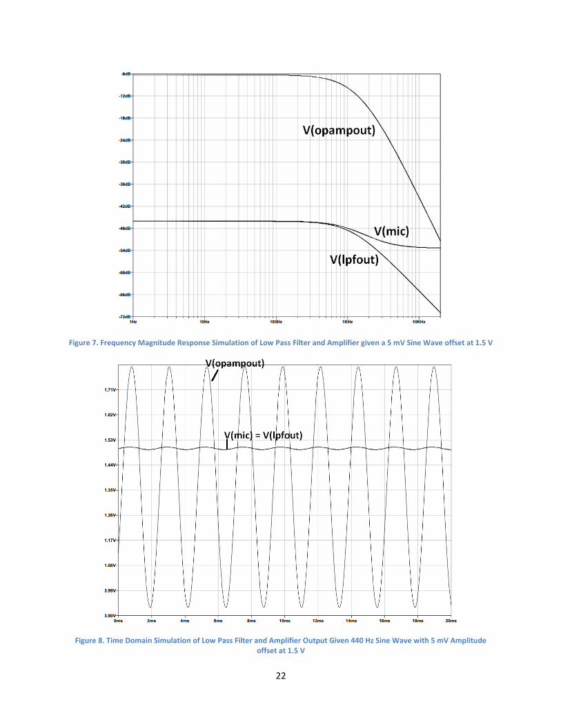
2.3 Audio Unit The audio unit is used to capture audio using a microphone and turn it into a digital number format
using an analog to digital converter for the control unit to process. A complete circuit used for
simulation for the audio unit is shown in Figure 6 with the simulations shown in Figure 7 and Figure 8.
The range of trumpet frequencies are from 165 Hz to 988 Hz [5]. Because of this, creating a filter to
lower the effects of harmonics and interference was required to ensure no aliasing occurs. The low pass
filter was placed before the amplifier because less filtering was needed than if it was placed after, where
the harmonics would be amplified to much higher levels.
There was one change made to the audio unit during the design phase, and that was adding a 2 kΩ
resistor in parallel with the input to the analog to digital converter, as shown in Figure 9. This change
was made because the DC offset at the input of the analog to digital converter would slowly drift up
over time because of characteristics documented in the MSP432 datasheet [6]. This change had no
effect on the overall requirements but allowed the amplifier’s output to stay within the input range of
the analog to digital converter. The final PCB design that contains the audio and processing unit is shown
in Figure 10.
5
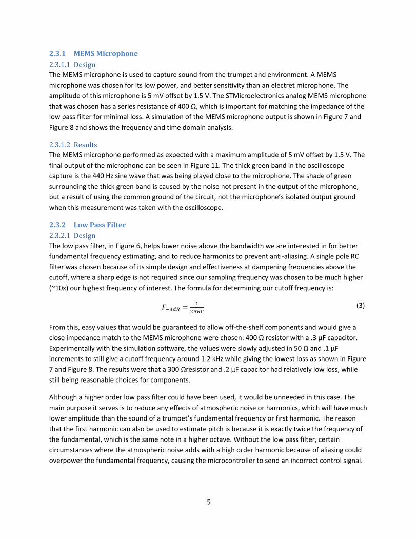
2.3.1 MEMS Microphone
2.3.1.1 Design
The MEMS microphone is used to capture sound from the trumpet and environment. A MEMS
microphone was chosen for its low power, and better sensitivity than an electret microphone. The
amplitude of this microphone is 5 mV offset by 1.5 V. The STMicroelectronics analog MEMS microphone
that was chosen has a series resistance of 400 Ω, which is important for matching the impedance of the
low pass filter for minimal loss. A simulation of the MEMS microphone output is shown in Figure 7 and
Figure 8 and shows the frequency and time domain analysis.
2.3.1.2 Results
The MEMS microphone performed as expected with a maximum amplitude of 5 mV offset by 1.5 V. The
final output of the microphone can be seen in Figure 11. The thick green band in the oscilloscope
capture is the 440 Hz sine wave that was being played close to the microphone. The shade of green
surrounding the thick green band is caused by the noise not present in the output of the microphone,
but a result of using the common ground of the circuit, not the microphone’s isolated output ground
when this measurement was taken with the oscilloscope.
2.3.2 Low Pass Filter
2.3.2.1 Design
The low pass filter, in Figure 6, helps lower noise above the bandwidth we are interested in for better
fundamental frequency estimating, and to reduce harmonics to prevent anti-aliasing. A single pole RC
filter was chosen because of its simple design and effectiveness at dampening frequencies above the
cutoff, where a sharp edge is not required since our sampling frequency was chosen to be much higher
(~10x) our highest frequency of interest. The formula for determining our cutoff frequency is:
𝐹−3𝑑𝐵 =1
2𝜋𝑅𝐶
(3)
From this, easy values that would be guaranteed to allow off-the-shelf components and would give a
close impedance match to the MEMS microphone were chosen: 400 Ω resistor with a .3 µF capacitor.
Experimentally with the simulation software, the values were slowly adjusted in 50 Ω and .1 µF
increments to still give a cutoff frequency around 1.2 kHz while giving the lowest loss as shown in Figure
7 and Figure 8. The results were that a 300 Ωresistor and .2 µF capacitor had relatively low loss, while
still being reasonable choices for components.
Although a higher order low pass filter could have been used, it would be unneeded in this case. The
main purpose it serves is to reduce any effects of atmospheric noise or harmonics, which will have much
lower amplitude than the sound of a trumpet’s fundamental frequency or first harmonic. The reason
that the first harmonic can also be used to estimate pitch is because it is exactly twice the frequency of
the fundamental, which is the same note in a higher octave. Without the low pass filter, certain
circumstances where the atmospheric noise adds with a high order harmonic because of aliasing could
overpower the fundamental frequency, causing the microcontroller to send an incorrect control signal.

6
2.3.2.2 Results
The low pass filter passed verification, Table 1,with the result of a cutoff frequency of 1.25 kHz. This is
well within the range specified by the requirement, and successfully prevented aliasing in the
microcontroller’s processing stage. The final output of the low pass filter can be seen in Figure 11.
Similar to the microphone output, the thick yellow band is the 440 Hz sine wave output from the low
pass filter, while the surrounding yellow shade is caused from using the common ground rather than the
microphone’s isolated ground when the measurement was taken with the oscilloscope. It is apparent
that the low pass filter is successfully reducing high frequency noise present in the microphone output,
because the low pass filter’s surrounding noise is much lower than the microphone’s, while the noise
from the common ground is unaffected.
2.3.3 Amplifier Circuit
2.3.3.1 Design
The amplifier amplifies the small voltage signal that the microphone produces so that the full range of
input voltages the analog to digital converter accepts is utilized. For this, a TLV2761 op-amp was chosen
because of its low power applications, and flat response across our band of interest. The gain for this
amplifier is determined by the formula:
𝐴𝑣 =𝑉𝑜
𝑉𝑖= (1 +
𝑅𝐹
𝑅𝐺) ∗ (
1
1 + 2𝜋𝑓 ∗ 𝑅𝐿𝑃𝐹𝐶𝐿𝑃𝐹)
(4)
From here, the amplifier circuit was determined to need a gain of 100 to amplify the small AC signal,
while not causing clipping on the analog to digital converter. The low pass filter and amplifier circuits
were created using modeling software, Figure 6, and the frequency and time domain results of the
circuit were simulated, Figure 7 and Figure 8, to view the waveform input of a 440 Hz sine wave to the
amplifier circuit and the output of the amplifier circuit into the analog to digital converter.
2.3.3.2 Results
The amplifier passed verification, Table 1, with the result that the small signal input is amplified by 36.90
dBV. Once again, common ground was used for the final output measurement instead of an isolated
ground and is shown in Figure 11. The reason that the noise from the common ground is not as
noticeable is because the y-axis divisions are spaced much larger apart (500 mV/div) compared to the
low pass filter and microphone divisions (50 mV/div). The common ground noise is still present in the
waveform, but since the waveform is at a much larger amplitude than the noise, the noise affects the
visual of the waveform much less.
2.3.4 Analog to Digital Converter
2.3.4.1 Design
The analog to digital converter is the key component that will allow an analog voltage to be converted
into a digital number for performing processing on the signal. The sampling frequency chosen for the
ADC will be 9.6 kHz, since frequencies above 1 kHz are not of interest, and by 5 kHz they are reduced by
21 dBV, which is around 1/10th the voltage compared to our band of interest. An observation while
simulating the audio unit using MatLAB was that 8 bits of resolution caused a much noisier frequency

7
spectrum than higher resolutions. 12 bits of resolution was found to be the best option as it requires no
extra software configuration yet reduces the noise in the sampled signal drastically. The third, and final
option for the analog to digital converter’s resolution was 14 bits, but this requires special hardware
configuration of the MSP432, so was not explored as a choice for this design.
2.3.4.2 Results
The analog to digital converter built into the MSP432 was successfully configured using the driver’s
configuration functions to sample at 9.6 kHz with 12 bits of resolution. This allowed the processing unit
to capture half a second of audio, for processing in a background task.
2.4 Processing Unit The processing unit is used for controlling the mechanical unit and the status LEDs based on the data
received from the analog to digital converter.
2.4.1 Microcontroller
2.4.1.1 Design
The microcontroller converts time domain to frequency domain, performs frequency analysis, controls
the user interface LEDs, and controls the mechanical unit. A MSP432P401R was chosen for this because
it has a built-in high-precision ADC that can be taken advantage of, if needed and is a very low power
microcontroller. Another benefit is the wide variety of debugging tools that Texas Instruments makes for
this microcontroller which will be very helpful when working with the signal processing aspects of this
project, done in software.
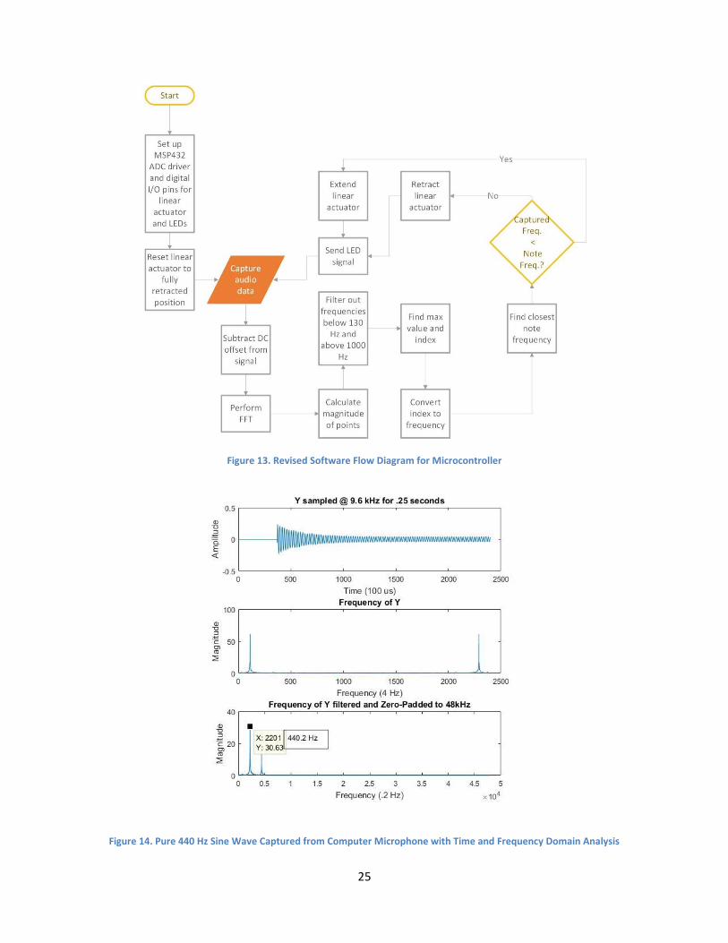
A model of the algorithm which was originally to be implemented on the microcontroller is shown in
Figure 12. This algorithm was modified, Figure 13, because padding to 48000 points was unneeded
because of the later index to frequency calculation performed. Another change was subtracting the DC
offset before performing FFT. The reason for this was because only the small signal voltage response
was desired, and it made the spectrum much clearer. The frequency plots of this modified algorithm,
Figure 14 and Figure 15, were created using MatLab. As is shown by the graphs, a trumpet’s harmonics
could still be present in the range of interest, but they are at a much lower magnitude, and can be
ignored completely. An alternative to doing this algorithm in software is to use a hardware frequency
counter, however, this would require stricter hardware filtering, and the harmonics of the trumpet
would be likely to interfere. From this, it can be seen that choosing the peak magnitude’s frequency as
the estimator is a reasonable solution.
The final circuit design of the processing unit is shown in Figure 16, and was placed on the same PCB
board as the audio unit as shown in Figure 10.
2.4.1.2 Results
The microcontroller passed both of its verifications, Table 2, by successfully attenuating all values
outside the frequencies of interest to 0 and performing a UART communication when connected to the
computer exactly every half a second. The way the timing requirement was accomplished while still

8
having a 2 Hz accuracy was by recording data in a background task while current data was being
processed and sent to the UART. Because of this, data was ready to be sent every half a second after the
first set of samples, which allowed for a fast reaction time by the processing unit when actually
performing tuning on the trumpet.
One problem during the assembly of the microcontroller was that the MSP432 was bricked due to faulty
code and became unrecoverable. Because of this issue, the audio input, the 3 LEDs, the linear actuator
control, the 3.3 V, and the ground connections had to be jumped to an external MSP432 Launchpad
evaluation board for progress to continue. No features of the evaluation board were used other than
the MSP432 processor, and because of the urgency there was no time to replace the bricked MSP432 so
this was the best solution.
2.4.2 Status LEDs
2.4.2.1 Design
The status LEDs will show whether the player is sharp or flat and will be powered by the microcontroller.
2.4.2.2 Results
The 2 red and 1 green LEDs all worked as expected, and successfully showed whether the trumpet was
in-tune, sharp, or flat. A future modification that could be made is placing the LEDs vertically instead of
horizontally so that the player can see whether the note is “high,” or sharp, or whether the note is
“low,” or flat.
2.5 Power Unit The power unit sources its power from a 9 V battery, regulates the voltage to 5 V, 3.3 V, and 2.5 V, and
distributes the power to various electronic and mechanical components of the tuner. The battery is user
removable and replaceable. When no battery is present, the tuner has the option to operate off an
external DC power supply between 13 V and 5.3 V.
2.5.1 Battery/DC Power
2.5.1.1 Design
The first design consideration regarding the battery is its output voltage. We designed our circuit to be
able to operate across a wide range of input voltages. It can operate with a maximum input voltage of
13 V, as limited by the 5 V DC-DC converter, and a minimum input voltage of 5.3 V, as limited by the 3.3
V linear voltage regulator. A battery with a high output voltage is needed such that we do not need to
use a boost converter between the battery and the regulators/DC-DC converter. Using a boost
converter is inefficient and will result in a shorter battery life. We decided that a 9 V battery is the best
choice since it has a usable operating voltage between 9 V and 5 V and it is compact enough to be
portable.
The next major design consideration is the output current. The battery must be able to output the peak
current draw of the linear actuator as well as the operating current for all the electrical components in
our tuner. The current draw of the linear actuator is dependent on how much force it applies. To

9
estimate the current it will draw, we experimentally recorded the forces required to move an ungreased
trumpet tuning slide and a greased tuning slide. These values were recorded in Table 5 and Table 6
respectively. We determined the peak force our actuator will have to apply is about 40 N from Table 5
We then cross referenced this force with the graph of Force vs Current in Figure 17. For our 210:1 6V
linear actuator, we determined that it will draw about 150 mA of current when applying 40 N of force.
Estimating the current draw for the rest of our electrical components as 5mA, we predicted the peak
current draw for all our electronics will be about 155mA. This peak current draw is well within the 9V
Duracell's limits.
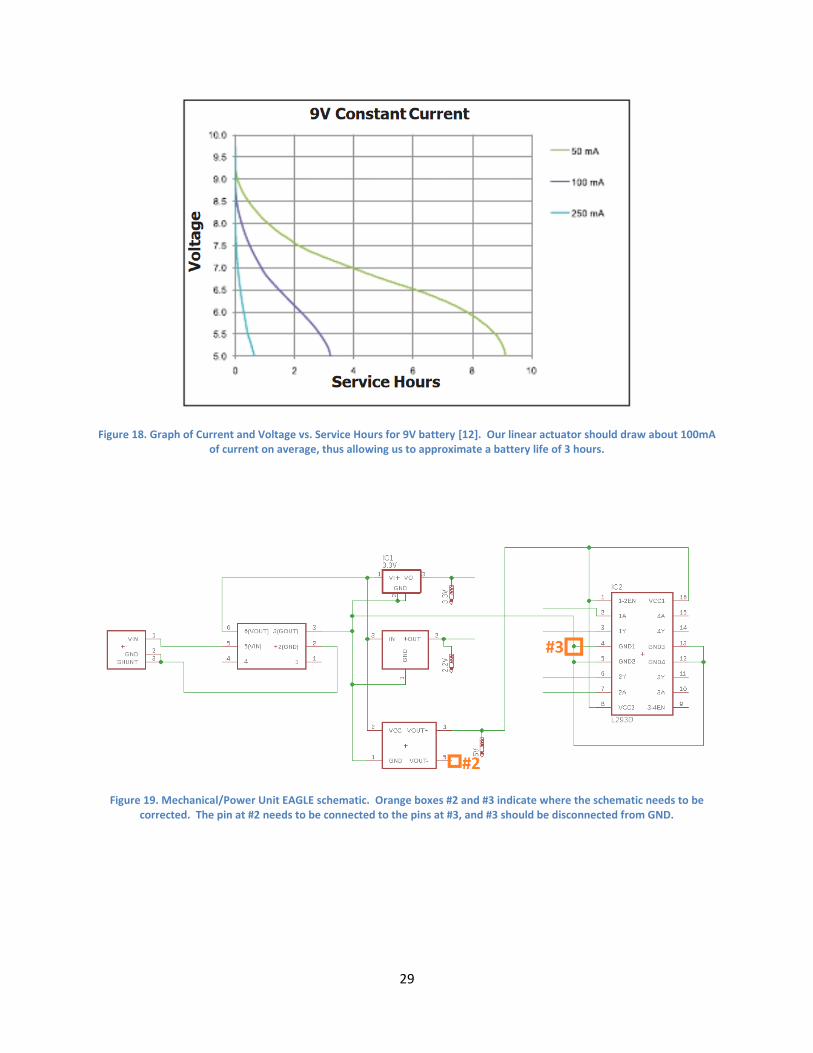
The last design consideration for the battery is its operating time. We assumed an average current draw
of about 100 mA while the tuner is operating. Using a Duracell MN1604 9 V battery as reference, we
determined that for an average current of 100mA the battery will operate within our desired voltage
range of 9 V to 5.3 V for nearly 3 hours. This estimate was obtained by referencing a current of 100 mA
with the Voltage vs. Service Hours graph in Figure 18. Then we assumed that each tuning session will
take about 5 minutes to complete. With a life time of 3 hours, we determined out tuner will be able to
complete about 36 tunings before the battery voltage drops below a useable level. The performance of
the battery depends on many factors, including some of we cannot control such as manufacturing
variability and temperature. To take these intro consideration, we set our goal for the number of
tunings each battery should complete at 28.
When the battery is not installed, the tuner is able to operate off a DC power supply through the barrel
connecter. This power supply can operate between 5.3 V and 13 V as limited by the 3.3 V regulator and
5 V DC-DC converter respectively. For our testing, we used an external 9 V DC power supply.
2.5.1.2 Results
The completed Power/Mechanical schematic is given in Figure 19 and the completed PCB is given in
Figure 20. Before we were able to use the Power/Mechanical PCB, we needed to make some
corrections. The first correction was for the three vias of the barrel connector, as marked by Box #1 in
Figure 20. They needed to be made larger, since they were printed too small for the pins on the barrel
connector to fit. In attempting to do this, the traces got damaged, so we had to run wires directly from
the pins of the barrel connector to the input pins on the switch. The other two corrections, regarding
the 5 V DC-DC voltage converter and the 2.5 V regulator are addressed in the Voltage Regulator/DC-DC
Voltage Converter section below.
After completing our corrections to the PCB, we tested it with our 9 V battery power source. When
powered with the 9 V battery, the 2.5 V regulator, 3.3 V regulator, and 5 V DC-DC converter all
functioned as expected. However, when attached to the trumpet, the tuner was unable to move the
tuning slide. Upon connecting the tuner to a 9 V DC power supply with current monitoring, we
determined that our tuner was drawing about 320 mA of current on average. This is much larger than
our anticipated 155 mA of peak current draw. After continued testing, we discovered that the
substituted microcontroller, an MSP432 Launchpad, was consuming on average 220 mA. The total 320
mA was much more current than our battery was able to supply and thus resulted in the tuner being
unable to operate on the 9V battery alone. This is why we failed our first requirement in Table 3.

10
Accounting for the 220 mA consumed by the MSP432 Launchpad, we can see that the rest of our circuit
was consuming about 100 mA, which is exactly what we predicted our average current to be. Knowing
this, if we had not needed the external Launchpad our tuner should have been able to perform with the
9 V battery as intended.
When tested with a 9 V DC power supply capable of providing up to 1 A, the linear actuator was able to
apply the amount of force needed to move the tuning slide. Our tuner still failed to complete a tuning
without assistance, but this was due to the housing sliding off the trumpet rather than the electronics.
2.5.2 On-Off Switch
2.5.2.1 Design
The on-off switch is responsible for disconnecting the battery or DC power supply from the rest of the
electronic components while the tuner is not in use.
2.5.2.2 Results
The on-off switch is reliably able to disconnect the power source from the test of the circuit.
2.5.3 Voltage Regulator/DC-DC Converter
2.5.3.1 Design
The voltage regulator circuit is responsible for converting the variable battery voltage to 3 constant
output voltages. These voltages power the audio unit, control unit, and mechanical unit. The DC-DC
converter outputs 5 V for the H-Bridge and linear actuator. One linear regulator outputs 3.3 V for the
microcontroller and the other regulator outputs 2.5 V for the MEMS microphone, amplifier, and ADC.
The 5 V DC-DC converter was chosen to power our linear actuator to increase our battery life. Although
the linear actuator is specified with a 6 V input voltage, a 6 V converter that can handle the 9 V to 5 V
operating range of the battery was not available. Instead, we chose a 5 V converter that could operate
across these voltages to maximize our battery life. The drawback to this is that the characterization of
our linear actuator given by Figure 17 is less accurate.
2.5.3.2 Results
The second correction we had to make to our PCB was for the biasing of the H-Bridge from the 5 V DC-
DC converter. The ground pins of the H-Bridge were supposed to be connected to the negative output
pin on the 5 V DC-DC voltage converter, as indicated by Box #2 in Figure 19 and Figure 20. Instead, we
incorrectly connected the ground pins of the H-Bridge to the common ground for the board, indicated
by Box #3 in Figure 19 and Figure 20. To fix this, the trace connecting the ground pins of the H-Bridge to
common ground was cut and a wire was soldered to connect them to the DC-DC converter's negative
output pin. The third minor correction we had to make was an issue with the labeling on the PCB and
Schematic. The 2.5 V regulator test pin was incorrectly labeled 2.2 V instead of 2.5 V. The labeling has
been corrected in Eagle for any future prints of the PCB.
After making these corrections, we tested the output of the regulators and DC-DC converter when
connected to a 9 V battery. All the voltages were within our specified tolerances in Table 3. We then
tested the output voltages when using a DC power supply and swept the voltage from 9 V to 5.3 V. All
three output voltages remained nearly constant and within our specified tolerances.

11
2.6 Mechanical Unit This unit is responsible for taking a signal from the control unit and appropriately moving the trumpet
tuning slide.
2.6.1 H-Bridge
2.6.1.1 Design
The H-Bridge is responsible for taking 5 V from the DC-DC converter and applying the correct voltage
polarity to the linear actuator in accordance with the control signals from the microcontroller. We used
two channels on the H-Bridge to bias our linear actuator, one for the red wire and one for the black
wire. Each channel receives one control signal from the microcontroller. When a channel is sent a logic
high of 3.3 V from the microcontroller, the channel will output a voltage of 5 V to a line on the linear
actuator. When sent a logic low below 2.5 V, the channel outputs ground. To extend the linear actuator,
the channel corresponding to the red wire on the actuator is sent a logic high signal and the channel
corresponding to the black wire is sent a logic low, thus biasing the actuator with +5 V. To retract the
actuator, the logic signals are switched, thus biasing the actuator with –5 V. To deactivate the actuator,
both channels are sent a logic low control signal.
2.6.1.2 Results
We hooked one channel of the H-Bridge up to the red input on the linear actuator and one channel to
the black input on the linear actuator. We then hooked one control signal wire from the microcontroller
up to each of the two channels. When the red channel was sent a logic high and the black channel sent
a logic low, the H-Bridge correctly applied at +5 V bias and the linear actuator extended. When the
control signals were swapped, a –5 V bias was applied and the linear actuator retracted. This passed our
performance requirement stated in Table 4.
2.6.2 Linear Actuator
2.6.2.1 Design
This component will be required to move the trumpet tuning slide in or out and will be powered directly from the H-Bridge. The linear actuator must supply up to 9.6 lbs of peak force to move an ungreased tuning slide according to our recorded data. Our recorded data for the peak force required to move a greased and ungreased turning slide is provided in Table 5 and Table 6. Following the tables is Figure 17 which provides a graph of the current draw from the actuator across a range of force applied. Finally, we have determined the 50 mm range of the linear actuator to be enough to adequately tune a trumpet while avoiding the risk of completely removing the tuning slide from the trumpet at 61 mm.
2.6.2.2 Results
When connected to the 9 V DC-DC power supply, the actuator operated as intended. It applied
sufficient force to move the tuning slide but could only function properly when manually held in contact
with the slide. This was due to issues with the housing. When connected to the 9 V battery, the battery
could not supply enough current to allow the actuator to apply enough force to move the tuning slide.
Due to both these issues, our actuator was never able to perform a complete tuning and thus failed our
requirement stated in Table 4.

12
3. Costs
3.1 Parts The cost of producing one unit in just parts is currently $191.93 as shown in Table 7. While buying many
of these components in bulk would help to lower the cost, the largest costs are the linear actuator, 5V
regulator, and the PCB boards. Their prices would go down very little if bought in bulk, so alternatives
for these components would need to be explored before commercializing the product if trying to
minimize the cost of the product.
3.2 Labor The total cost of labor in the development of this product was $7,823.63 as shown in Table 7. This figure
was determined using a $70,000 salary per year per engineer and taking the hourly rate at this salary
multiplied by the estimated time each engineer spent in development on the product.

13
4. Conclusion
4.1 Accomplishments Our first prototype managed to accomplish many of our goals. Our project correctly identifies the
current pitch of our trumpet and discerns if the trumpet is currently flat or sharp consistently.
Accordingly, our circuitry manipulates the linear actuator input such that it attempts to move the tuning
slide in the correct direction. On a high level, we managed to create a working design.
4.2 Ethics Our project did not involve human and animal testing, so we were mostly concerned about conducting
ourselves in accordance with the IEEE Code of Ethics. Referencing this code:
Our project will not endanger the safety, health, and welfare of the public and the environment. We do
not know of any conflicts of interest, but we will resolve them properly if they come up. Our claims are
realistic, and we will maintain a consistent record of data throughout the design process. With our
combined experience and knowledge, we deem ourselves qualified for the technological tasks that this
project will require, and we will seek out honest criticism and review when needed. We will reject
bribery, and we will not utilize our project to injure others or harm their property. We will treat our
colleagues and our teammates with the respect all men and women deserve, and we will hold ourselves
to following this code of ethics. [7]
4.3 Safety Our project contains moving mechanical parts. While we never anticipated sudden, forceful movements
from our design we had to conduct ourselves carefully around these mechanical parts. We ensured that
the mechanical parts were consistently safe to be around before testing the trumpet tuner, as testing
required our face to be rather close to the apparatus. These same risks will apply to our end user as well,
so ensuring these parts pose no risk to the user was important.
4.4 Future work One of the main items to improve upon is a more stable casing for the design. Currently, while the
design acts as intended, the casing is loose enough to where the force output by the linear actuator is
being applied improperly, causing torque around the bit attached to the linear actuator, or even shifting
the entire casing backward. Our algorithm could also be improved to utilize the MUSIC algorithm [8]
which decomposes the trumpet’s covariance matrix to analyze harmonics, rather than relying on peak
magnitude response. The main benefit of this other algorithm would be that you’d be able to get a much
higher resolution and could determine the exact octave of the fundamental frequency. Smaller items
that could be improved upon are a more compact PCB design on a single board, better filtering and

14
amplification of the signal to use the full range of the analog to digital converter’s specified input range,
and a different choice in battery.
15
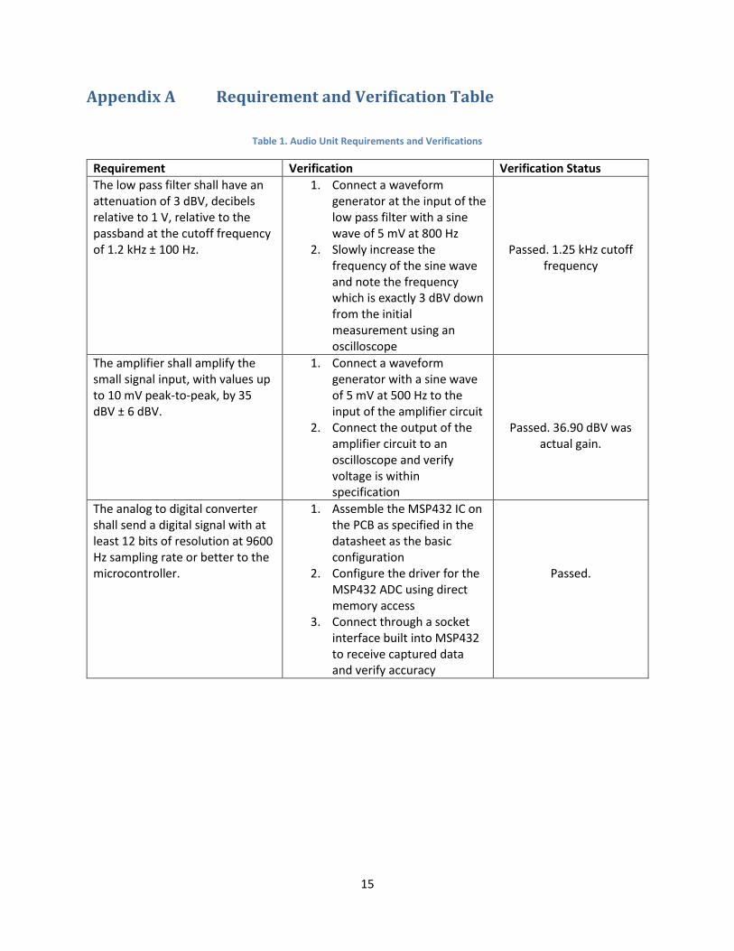
Appendix A Requirement and Verification Table
Table 1. Audio Unit Requirements and Verifications
Requirement Verification Verification Status
The low pass filter shall have an attenuation of 3 dBV, decibels relative to 1 V, relative to the passband at the cutoff frequency of 1.2 kHz ± 100 Hz.
1. Connect a waveform generator at the input of the low pass filter with a sine wave of 5 mV at 800 Hz
2. Slowly increase the frequency of the sine wave and note the frequency which is exactly 3 dBV down from the initial measurement using an oscilloscope
Passed. 1.25 kHz cutoff frequency
The amplifier shall amplify the small signal input, with values up to 10 mV peak-to-peak, by 35 dBV ± 6 dBV.
1. Connect a waveform generator with a sine wave of 5 mV at 500 Hz to the input of the amplifier circuit
2. Connect the output of the amplifier circuit to an oscilloscope and verify voltage is within specification
Passed. 36.90 dBV was actual gain.
The analog to digital converter shall send a digital signal with at least 12 bits of resolution at 9600 Hz sampling rate or better to the microcontroller.
1. Assemble the MSP432 IC on the PCB as specified in the datasheet as the basic configuration
2. Configure the driver for the MSP432 ADC using direct memory access
3. Connect through a socket interface built into MSP432 to receive captured data and verify accuracy
Passed.

16
Table 2. Processing Unit Requirements and Verifications
Requirement Verification Verification Status
The microcontroller shall attenuate frequencies below 130 Hz and above 1000 Hz by at least -6 dBV
1. A socket connection will be established from a computer to the microcontroller to verify that data captured has been filtered properly
Passed. All frequencies
outside range are attenuated to 0, or with
–∞ dBV gain.
The microcontroller shall complete one cycle of capturing audio and computation on that audio within 500 ms.
1. One digital I/O pin will be connected to an oscilloscope and a debug signal will be sent at the beginning of every cycle for the time to be determined
Passed. UART sending every half a second on
timestamps.
The Status LEDs shall be clearly visible and be made up of 2 red and 1 green to show the current status of the tuner.
1. When assembled, 3 sine wave tones should be played from a tone generator: a 430 Hz tone, a 440 Hz tone, and a 450 Hz tone. A different LED will light up for each of these different tones.
Passed.
17
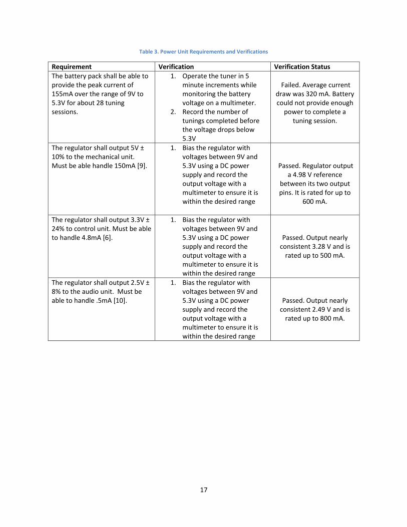
Table 3. Power Unit Requirements and Verifications
Requirement Verification Verification Status
The battery pack shall be able to provide the peak current of 155mA over the range of 9V to 5.3V for about 28 tuning sessions.
1. Operate the tuner in 5 minute increments while monitoring the battery voltage on a multimeter.
2. Record the number of tunings completed before the voltage drops below 5.3V
Failed. Average current
draw was 320 mA. Battery could not provide enough
power to complete a tuning session.
The regulator shall output 5V ± 10% to the mechanical unit. Must be able handle 150mA [9].
1. Bias the regulator with voltages between 9V and 5.3V using a DC power supply and record the output voltage with a multimeter to ensure it is within the desired range
Passed. Regulator output
a 4.98 V reference between its two output pins. It is rated for up to
600 mA.
The regulator shall output 3.3V ± 24% to control unit. Must be able to handle 4.8mA [6].
1. Bias the regulator with voltages between 9V and 5.3V using a DC power supply and record the output voltage with a multimeter to ensure it is within the desired range
Passed. Output nearly consistent 3.28 V and is
rated up to 500 mA.
The regulator shall output 2.5V ± 8% to the audio unit. Must be able to handle .5mA [10].
1. Bias the regulator with voltages between 9V and 5.3V using a DC power supply and record the output voltage with a multimeter to ensure it is within the desired range
Passed. Output nearly consistent 2.49 V and is
rated up to 800 mA.

18
Table 4. Mechanical Unit Requirements and Verifications
Requirement Verification Verification Status
The H-Bridge shall toggle power to the linear actuator as well as invert the 5V bias across the actuator to reverse actuator motion. Must be able to pass up to 150 mA.
1. Bias the H-Bridge using a 5V DC power supply and apply 3V control signals from the microcontroller to toggle each of the driver outputs.
2. Measure output voltage of each driver output with a multimeter to ensure the output changes between 5V and 0V when toggled by the microcontroller
Passed. H-Bridge outputs +5 V or GND to each line following the input signal from the processing unit.
H-Bridge is rated up to 600 mA.
Linear actuator shall apply up to 9.6lbs of force to move the tuning slide over a distance of 50mm.
1. Connect the end of the actuator to a force gauge and apply a 5V bias with the current limited to 150mA from a DC power supply.
2. Record the peak force and compare to our maximum required force.
Failed. Power limitations
prevented the linear actuator from functioning at full capacity. Housing
issues prevented actuator from properly moving
trumpet slide.

19
Appendix B Tables and Figures
Figure 1. Block Diagram of the Auto-Tuner
Figure 2. Physical Model Concept

20
Figure 3. 3D Rendered Casing Draft
Figure 4. 3D Rendered Casing Final Design of Main Body

21
Figure 5. 3D Rendered Casing Final Design of Slide Connector
Figure 6. Circuit Diagram for Simulation of Low Pass Filter and Amplifier Output with MEMS Microphone
22
Figure 7. Frequency Magnitude Response Simulation of Low Pass Filter and Amplifier given a 5 mV Sine Wave offset at 1.5 V
Figure 8. Time Domain Simulation of Low Pass Filter and Amplifier Output Given 440 Hz Sine Wave with 5 mV Amplitude offset at 1.5 V

23
Figure 9. Final Circuit Design for Audio Unit
Figure 10. Final PCB Design of Audio and Processing Unit

24
Figure 11. Intermediate Results of the Audio Unit Captured by an Oscilloscope with a Large Input 440 Hz tone as Input to the Microphone
Figure 12. Proposed Software Flow Diagram for Microcontroller
25
Figure 13. Revised Software Flow Diagram for Microcontroller
Figure 14. Pure 440 Hz Sine Wave Captured from Computer Microphone with Time and Frequency Domain Analysis

26
Figure 15. Out-of-tune Trumpet Played at B (440 Hz) Captured from Computer Microphone with Time and Frequency Domain Analysis

27
Figure 16. Final Circuit Design for Processing Unit
Table 5. Force Required to Move Ungreased Tuning Slide
Direction Force (lbs)/(N)
Out 9.6/42.7
In 9.6/42.7
Out 9.5/42.3
In 8.0/35.6
Out 9.2/40.1
In 8.5/37.8

28
Table 6. Force Required to Move Greased Tuning Slide
Direction Force (lbs)/(N)
Out 7.2/32.0
In 3.6/16.0
Out 6.0/26.7
In 4.4/19.6
Out 6.9/30.7
In 4.1/18.2
Out 5.3/23.6
In 4.4/19.6
Figure 17. Force vs. Current of Linear Actuator [11]. Our Actuator is the 210:1 – 6V configuration and is denoted by the solid red line. It is seen here that a force of 40N will result in a current draw of about 150mA.
29
Figure 18. Graph of Current and Voltage vs. Service Hours for 9V battery [12]. Our linear actuator should draw about 100mA of current on average, thus allowing us to approximate a battery life of 3 hours.
Figure 19. Mechanical/Power Unit EAGLE schematic. Orange boxes #2 and #3 indicate where the schematic needs to be corrected. The pin at #2 needs to be connected to the pins at #3, and #3 should be disconnected from GND.

30
Figure 20. Mechanical/Power PCB made in EAGLE. The orange boxes #1, #2, and #3 correspond to changes that needed to be made to the PCB. #1 indicates the barrel connector vias that need to be larger. Pins at #2 and #3 need to be connected and
the GND trace to #3 needs to be cut.

31
Table 7. Bill of Materials and Labor
Part Distributor Price
MSP432P401RIRGCT Microprocessor DigiKey $7.03
MP23AB01DHTR Analog MEMS Microphone DigiKey $3.96
TLV2761IDBVR IC Op-amp DigiKey $1.95
L12 Linear Actuator 50mm 210:1 6V Limit Switch RobotShop $70.00
2.1mm Barrel Jack Adapter RobotShop $0.95
Switching Power Supply 9V 1A RobotShop $6.95
9V to 2.1mm Barrel Jack Adapter V2 RobotShop $1.70
PCBs PCBWay $45.00
3D Printed Casing 3DHubs $20.00
Screws Home Depot $1.00
Assorted Resistors, Capacitors, LEDs (Est.) DigiKey $10.00
LD1117S25TR 2.5V Regulator Mouser $0.41
UA78M33 3.3V Regulator Mouser $0.68
TRN 3-0511 5V Voltage Regulator Mouser $18.39
L293D H-Bridge Mouser $3.91
Total Price: $191.93
Laborer Hours
James Lithgow 35
Tyler Baldassone 30
Lowie Rodriguez 28
Multiplier 2.5
Price/Hour $33.65
Total Cost of Labor: $7,823.63
Total Cost of Project: $8,015.56

32
References
[1] E. Schafer, "Tuning Tendencies," University of Tennessee at Chattanooga, [Online]. Available:
https://www.utc.edu/faculty/erika-schafer/musiceducatorresources/tuning.php. [Accessed 8
February 2018].
[2] Theta Music Trainer, "Pitch Memory," Theta Music Trainer, [Online]. Available:
https://trainer.thetamusic.com/en/content/pitch-memory. [Accessed 8 February 2018].
[3] Sengpiel Audio, "Cents to Frequency Ratios," Sengpiel Audio, [Online]. Available:
http://www.sengpielaudio.com/calculator-centsratio.htm. [Accessed 4 February 2018].
[4] L. Haken, ECE402 - Prof Haken - Handout for Lecture 10, Champaign-Urbana, 2018.
[5] Zytrax, "Tech Stuff - Frequency Ranges," Zytrax, 1 July 2016. [Online]. Available:
http://www.zytrax.com/tech/audio/audio.html. [Accessed 25 January 2018].
[6] Texas Instruments, "MSP432P401R, MSP432P401M SimpleLink™ Mixed-Signal Microcontrollers
datasheet (Rev. G)," Texas Instruments, 1 September 2017. [Online]. Available:
http://www.ti.com/lit/ds/slas826g/slas826g.pdf. [Accessed 8 February 2018].
[7] IEEE, "IEEE Code of Ethics," IEEE, [Online]. Available:
https://www.ieee.org/about/corporate/governance/p7-8.html. [Accessed 5 February 2018].
[8] B. L. Evans, "MUSIC Algorithm," 30 August 1994. [Online]. Available:
https://ptolemy.berkeley.edu/papers/96/dtmf_ict/www/node5.html. [Accessed 2 May 2018].
[9] RobotShop Inc., "L12 Linear Actuator 50mm 210:1 6v limit-switch," RobotShop Inc., [Online].
Available: https://www.robotshop.com/en/firgelli-technologies-l12-actuator-50mm-210-1-6v-
limit-switch.html#description. [Accessed 8 February 2018].
[10] STMicroelectronics, "MP23AB01DH - High-performance MEMS microphone," STMicroelectronics,
[Online]. Available: http://www.st.com/content/st_com/en/products/audio-ics/mems-
microphones/mp23ab01dh.html. [Accessed 8 February 2018].
[11] Actuonix Motion Devices Inc, "Actuonix L12 Datasheet," Actuonix Motion Devices Inc, 1 September
2016. [Online]. Available: https://www.robotshop.com/media/files/pdf/L12_Datasheet-2.pdf.
[Accessed 17 February 2018].

33
[12] Duracell, "Duracell MN1604," Duracell, [Online]. Available:
https://d2ei442zrkqy2u.cloudfront.net/wp-
content/uploads/2016/03/MN1604_6LP3146_US_CT1.pdf. [Accessed 17 February 2018].