automatic train stopping using the lncp and jmrirr-cirkits.com/clinics/gr-2012-stopping.pdf ·...
TRANSCRIPT

●Automatic Train Stopping using the LNCP and JMRI
Clinics in this series:
Automatic Train Stopping using the LNCP and JMRI
7:00 PM, Tuesday, July 31st
8:30 PM, Friday, August 3rd
Aspect Signaling with JMRI/PanelPro4:00 PM, Tuesday, July 31st
7:00 PM, Friday, August 3rd
Clinics in this series:
Automatic Train Stopping using the LNCP and JMRI
7:00 PM, Tuesday, July 31st
8:30 PM, Friday, August 3rd
Aspect Signaling with JMRI/PanelPro4:00 PM, Tuesday, July 31st
7:00 PM, Friday, August 3rd
Dick Bronson - RRCirKits, Inc.

Resources
Web Sites http://www.rrsignalpix.com/index.html A site for Signals and rules.
By Zachary Gillihan
http://www.ctcparts.com/ An excellent site for CTC information.By Michael Burgett
http://www.RR-CirKits.com/ Our web site for signal control hardware.By Dick Bronson
Web Sites
Basic Train Automation
What are the primary requirements of automated train control?
Obey Absolute Signals Stop and Start Realistically Loco Sounds Follow the Actions
What are some secondary requirements of automated train control?
Slowing for approach signals Sounds at grade crossings Automated Routing
Signal System Types

How to stop a train
Some ways to stop a train? Cut the power to the track
Unrealistic stopping No sounds while stopped
Control the track voltage Limited use in DCC Can be used to slow trains, but not to stop
realistically

How to stop a train
Command the trains using DCC Requires knowledge of which engine or engines
need to be controlled How to tell what engines to control?
Digitrax Transponding Bi directional DCC with cutouts Train tracking in software such as JMRI RFID, RPS, Scanners, Etc.
Problems with train tracking Limited decoder choices for hardware options Software can easily lose track of trains Inmature and/or high cost technology for RFID etc. Some options do not scale well.

Brake on DC
Brake on DC
This Schematic showing how to wire Brake on DC is from Loy's excellent web site.
Unfortunately there are serious problems with this method.
It causes short circuits between the DC and DCC requiring double lamps at each block.

Brake on DC
No detection of stopped train in stopping block Gets really difficult for bi-directional running on
single track lines How do you get running again? You need to
delay the signal action long enough for the train to not stop itself as soon as it moves onto the next block causing the signal to go red again.
There is a better way, so lets not cross this option off the list just yet.

Transponding Braking Section
Transponding Braking Section
Using Transponding or Bi-Directional DCC eliminates the issues with shorts and lamps, but doesn't do much for the other issues.
Special detectors and special decoders are required for ALL blocks and engines

Getting Brake on DC to Work
Lets think about some ways to get the brake on DC to work better.
First lets try to use a simple series diode to cut out half of the DCC signal. That should give us pulsed DC instead of the normal DCC.
Getting Brake on DC to Work
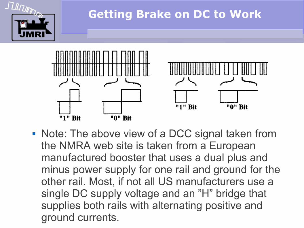
Note: The above view of a DCC signal taken from the NMRA web site is taken from a European manufactured booster that uses a dual plus and minus power supply for one rail and ground for the other rail. Most, if not all US manufacturers use a single DC supply voltage and an ”H” bridge that supplies both rails with alternating positive and ground currents.

Getting Brake on DC to Work
The decoder itself has no absolute reference to the real world ground, so it can not tell the difference.
The decoder's input has a full wave bridge rectifier so cutting out half of the DCC pulses does not actually change the decoders internal voltage. I.e. It does not slow the locomotive at all.

Getting Brake on DC to Work
I almost convinced myself that it wouldn't work, but manufacturers web sites and other experimenters said it would.
I decided to try it by sticking a power rectifier in series with my booster. My trains did NOT stop or even slow down.

Getting Brake on DC to Work
Fortunately Lee Wheelbarger was watching this experiment and said lets call QSI and ask them why it doesn't work like they say it will.
A few minutes later I was on the phone with Fred at QSI and he was asking me questions and having me check scope traces of the resulting DCC wave forms. What we determined was that the rectifiers that I used were too slow at turning off, and the DCC signal was still passing through enough to be seen by the decoder.

Getting Brake on DC to Work
Replacing the rectifiers with a 1A Shottkey diode made things work OK for my testing.
I then ordered some 10A Shottkey diodes and initial tests indicated they also were fast enough to work OK.
I then rewired a section of my own layout and tried again with a light engine in a stopping block. It glided right on past the red signal as if it wasn't even there. I then placed a test LED on the track to see if I had wired the relay correctly and it was. By that time the engine had come around again and obediently stopped.

Getting Brake on DC to Work
I had to unclip the test LED to let the engine go past, and as soon as I did it took off again. (before closing the relay again)
My final conclusion to all this is that with no external load on the tracks even a fast diode has enough internal capacity for the decoder to see the full DCC pulse and continue merrily on its way.
I added snubbers to the control circuits and finally things work as advertized.
Getting Brake on DC to Work
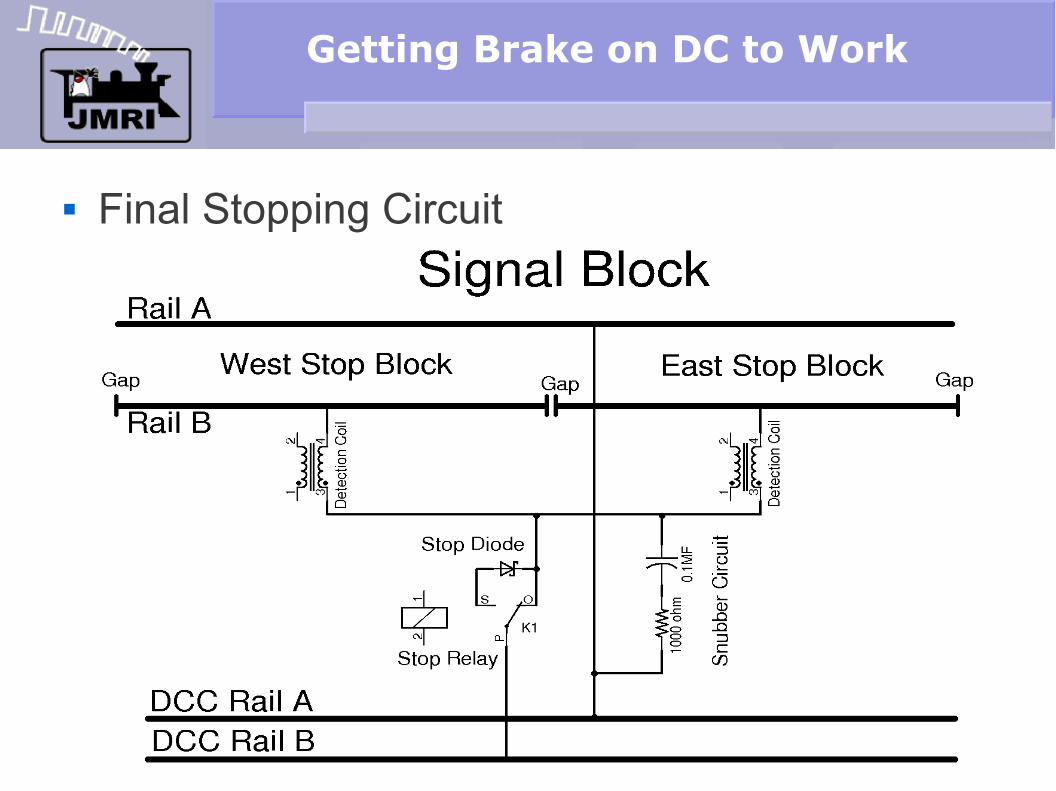
Final Stopping Circuit

When to stop a train
When to Stop a train If the train enters the East detection block, THEN
enters the West detection block AND the West signal is set to STOP, then the train should stop.
When to stop a train
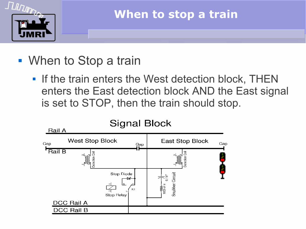
When to Stop a train If the train enters the West detection block, THEN
enters the East detection block AND the East signal is set to STOP, then the train should stop.

Track Circuits
The above circuits assume that the stopping portion is ½ of the signal block length. If it is shorter or longer then use the following circuit.

Circuit Considerations
Circuit Considerations The detection circuits must be
connected after the relay contact. If not multiple contacts will be required.
The snubber must be wired between the stop relay and the detection circuits. If not, then it will trigger the detection.
The stop diode should be able to safely carry the DCC short circuit current in case of a derailment.
The stopping blocks should all be the same lengths to permit tuning the decoders to respond in similar ways at each stop signal. Use shorter or overlapping blocks as required.
Circuit Considerations
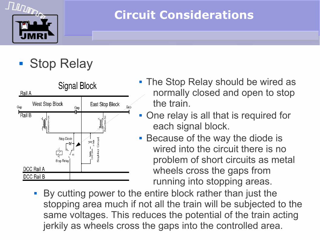
Stop Relay The Stop Relay should be wired as
normally closed and open to stop the train.
One relay is all that is required for each signal block.
Because of the way the diode is wired into the circuit there is no problem of short circuits as metal wheels cross the gaps from running into stopping areas.
By cutting power to the entire block rather than just the stopping area much if not all the train will be subjected to the same voltages. This reduces the potential of the train acting jerkily as wheels cross the gaps into the controlled area.

Using LNCP Logic
The LNCP has built in logic especially designed to do this job easily.
We created a special IF x AND-THEN y function. For example IF 'block East' AND-THEN 'block West' do 'Action'.
The LNCP logic can watch signal aspects such as 'Stop.' Watching a mast's aspect is much easier than trying to watch the color of several different signal heads to determin its aspect. Using the new JMRI Masts capability simplifies the job greatly. The logic simply determines the direction of travel, THEN checks the appropriate signal's aspect. If it is 'Stop' then the stop relay is actuated.

DecoderPro view of LNCP 'Logic A'

Using LNCP Logic
Because of the IF x AND-THEN y logic function there is no problem with detecting the direction of the train passing through the block. We simply wait for first one block then the next to become active.
Conditional 1 Direction detection Logic Block 1 then Block 2 sends message LS103C.
Conditional Direction cancling Logic. Both Block 1 and Block 2 are not occupied sends message LS103T.
LS103 controls a East-West icon on the panel.

Using LNCP Logic
Because of the IF x AND-THEN y logic function there is no problem with deciding if a signal has been at 'Stop', or goes to 'Stop' again after the train has already stopped and been allowed to proceed again.
Conditional 5 Stop detection Logic: Mast 2 Stop AND-THEN direction detected sends message LT4T. (Stop Relay)
Conditional Stop Canceling Logic. Stop Aspect AND Direction detection is false sends message LT4C which releases the Stop relay.

Questions?
Questions ?

Questions?
Questions ?