autogard torque limiter 400 series · 3 features and benefits: • proven design with thousands of...
TRANSCRIPT

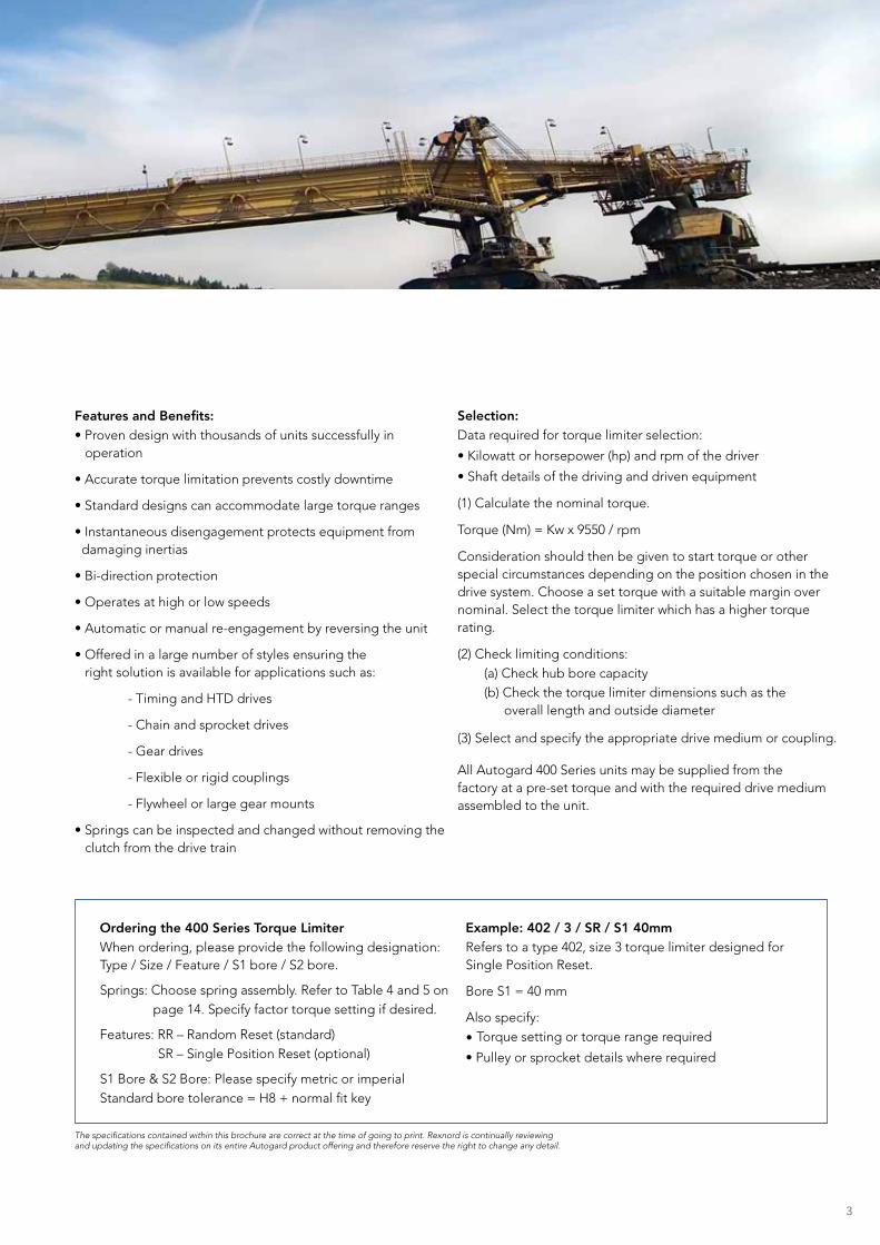
Autogard Torque Limiter 400 Series
Autogard Torque Limiter 400 Series Overview

2
Autogard Torque Limiter 400 Series For more than 80 years, Autogard® products have led the industry in overload protection with high-quality products, design innovation and production. Autogard products are manufactured to meet ISO 9001 using the latest machine tools and high-quality materials.
The 400 Series has been designed to meet the need for a high- and low-speed, free-wheeling torque limiter. The 400 Series differs from other ball detent designs by incorporating a unique reverse-to-reset function using two sets of balls on concentric pitch circles, providing longer life than competitive models. Working like a mechanical “fuse” to protect the weakest member of the drive train, the most effective location for the 400 Series is as close as possible to the component being protected.
In the normal drive condition, torque is transmitted through the drive balls ‘A.’ The inner strut balls ‘B’ are designed to carry no load during this time.
Disengagement on overload When an overload condition occurs, the drive balls roll out of their seats forcing the slide plate ‘C’ and drive plate ‘D’ apart. The cage plate ‘E,’ strut balls and drive balls all rotate until the cage plate hits a stop located in the slide plate. At this point the spring pressure has been transferred from the drive balls to the strut balls. The strut balls prevent the drive balls from re-engaging the drive plate. The coupling or driven media attached to adapter ‘G’ is now completely free to rotate. Although the 400 Series has been designed to run freely after disengagement, it is recommended that a shutdown switch is incorporated to avoid wear.
Re-engagement Re-engagement occurs when either the driving side is reversed, or the driven side is advanced. Pawl ‘F’ engages the cage plate ‘E’ and rotates it until the drive balls are re-seated. Resetting must be done at low speed to permit the engaging mechanism to function properly in either direction and to prevent potential damage.
The resetting can be done manually or automatically by slowly inching the motor in reverse.
Single Position Reset (SR) designs are also available and must be specified at the time of ordering. These reset in a constant angular position.
F
G
E
D
B
A
C
The 400 Series comes as standard as a Random Reset style Torque Limiter. This gives the following maximum angles of rotation to re-engage.
Size Max rotation to reset
1 60˚
2 67.5˚
3 30˚
4 30˚
5 30˚
6 25.7˚
Letters above correspond to paragraphs on the left.
3
Features and Benefits: • Proven design with thousands of units successfully in operation
• Accurate torque limitation prevents costly downtime
• Standard designs can accommodate large torque ranges
• Instantaneous disengagement protects equipment from damaging inertias
• Bi-direction protection
• Operates at high or low speeds
• Automatic or manual re-engagement by reversing the unit
• Offered in a large number of styles ensuring the right solution is available for applications such as:
- Timing and HTD drives
- Chain and sprocket drives
- Gear drives
- Flexible or rigid couplings
- Flywheel or large gear mounts
• Springs can be inspected and changed without removing the clutch from the drive train
Selection: Data required for torque limiter selection:
• Kilowatt or horsepower (hp) and rpm of the driver
• Shaft details of the driving and driven equipment
(1) Calculate the nominal torque.
Torque (Nm) = Kw x 9550 / rpm
Consideration should then be given to start torque or other special circumstances depending on the position chosen in the drive system. Choose a set torque with a suitable margin over nominal. Select the torque limiter which has a higher torque rating.
(2) Check limiting conditions: (a) Check hub bore capacity(b) Check the torque limiter dimensions such as the
overall length and outside diameter
(3) Select and specify the appropriate drive medium or coupling.
All Autogard 400 Series units may be supplied from the factory at a pre-set torque and with the required drive medium assembled to the unit.
Example: 402 / 3 / SR / S1 40mm Refers to a type 402, size 3 torque limiter designed for Single Position Reset.
Bore S1 = 40 mm
Also specify:• Torque setting or torque range required
• Pulley or sprocket details where required
The specifications contained within this brochure are correct at the time of going to print. Rexnord is continually reviewing and updating the specifications on its entire Autogard product offering and therefore reserve the right to change any detail.
Ordering the 400 Series Torque Limiter When ordering, please provide the following designation: Type / Size / Feature / S1 bore / S2 bore.
Springs: Choose spring assembly. Refer to Table 4 and 5 on page 14. Specify factor torque setting if desired.
Features: RR – Random Reset (standard) SR – Single Position Reset (optional)
S1 Bore & S2 Bore: Please specify metric or imperial Standard bore tolerance = H8 + normal fit key

Applications
Conveyors
Shredders
Reel Stands
Billet Transfer Drives
Extruders
4

5
Model 402
SizeSmallest Sprocket (No. of teeth — see ) Smallest Diameter
mm3/8” pitch 1/2” pitch 5/8” pitch 3/4” pitch 1” pitch
1 19 15 13 - - 46
2 27 21 17 15 12 70
3 34 27 22 19 15 92
4 - 30 24 21 17 104
5 - 38 31 27 21 139
6
2
1
3
Model 402 for use with sprockets, pulleys or gears. Supplied complete with bearing and a choice of mounting holes.
SizeMax
Bore S1 mm
Dmm
Emm
Gmm
Hmm
K Maxmm
Jmm
L Maxmm
Mmm
O Maxmm
Pmm
Qmm
Rmm
Smm
X1mm
Z1mm
X2mm
X3mm
Z2mm
1 16 62 55 25 - 33.5 14 83 - 25 30 35 38 - - - 3 x M3 3 x ø4 6
2 28 112 90 40 - 57 37 148 - 44.5 46 52 61 - - - 3 x M4 3 x ø5 9
3 40 146 120 55 4.76 55 35 160 95 43 63 75 80 114 7 x M10 15 3 x M6 3 x ø8 11
4 50 168 136 65 4.76 100 36 212 122 84 72 85 90 144 8 x M12 15 3 x M8 3 x ø10 11
5 75 222 190 100 6.35 134 56 284 155 116 107.95 120 125 184 8 x M16 23 4 x M8 4 x ø10 11
6 100 260 235 140 181 25 376
3 41
3
2
SizeTorque
Max Speed rpm
WeightKg
Mass Moment of Inertia
MinNm
MaxNm
Hub SideKgm2
Flange SideKgm2
1 3 28 3600 1.0 0.0002 0.0002
2 4 226 3600 5.2 0.0036 0.0041
3 27 678 3600 10.1 0.013 0.013
4 45 1130 2000 14.8 0.024 0.024
5 100 2542 2000 36.4 0.118 0.090
6 1100 5650 1800 55 0.266 0.170
For higher torque applications, consult Rexnord. Higher speeds may be allowed under certain conditions. Please consult Rexnord.Weights and moments of inertia apply to max (S1) bores.
1
2
3
3
3
2
1
PCD FOR Q PCD FOR R
PCD FOR S
X1 HOLES x Z1 DEEPEQUISPACED ON PITCH CIRCLE DIAMETER (PCD) FOR S
X2 HOLES x Z2 DEEPX3 HOLES x Z2 DEEPEQUISPACED ON PCD FOR Q AND R
Ø G
h7
Ø E
Ø (D
IAM
ETER
) D
Ø M
j7
L
JH
O
SEE T
ABLE
3, PA
GE 13
K
Ø P
H7
DRIVE MEDIA FIXING HOLES
Ø S
1
5
For max bores greater than 25mm, use rectangular parallel keys.For size 6, the drive medium must be fitted with suitable bearings and fixing. Please specify or consult Rexnord for assistance.For size 6, clearance is required for torque adjustment. See Table 1 page 12.Hub can be shortened to suit narrower drive media - please specify with order.h6 tolerance.
1
2
3
4
B type sprocket recommended. For multiple sprockets, consult Rexnord.The diameter quoted is to the bottom of a V pulley groove or the ID of the flange on a timing pulley.Please consult Rexnord for specifications.
1
2
3
5
6
Model 403
SizeTorque
Max Speed rpm
Weightkg
Mass Moment of Inertia MR2
MinNm
MaxNm
Hub Sidekgm2
Flange Sidekgm2
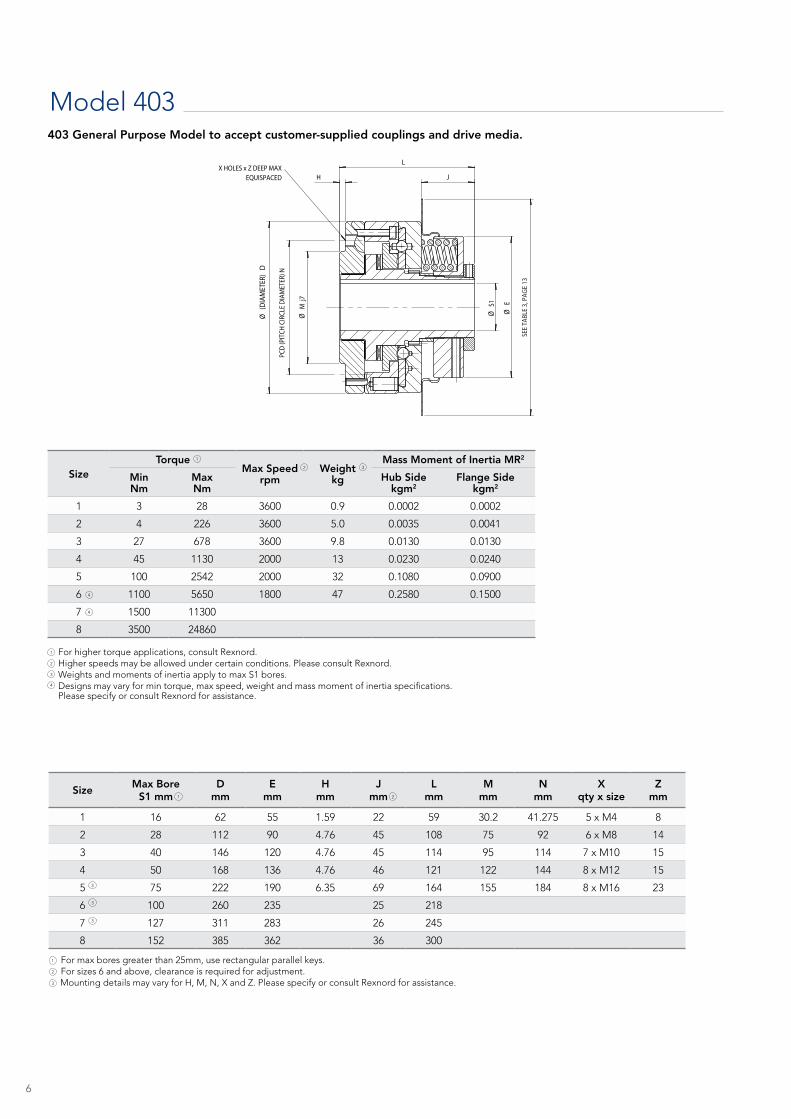
1 3 28 3600 0.9 0.0002 0.0002
2 4 226 3600 5.0 0.0035 0.0041
3 27 678 3600 9.8 0.0130 0.0130
4 45 1130 2000 13 0.0230 0.0240
5 100 2542 2000 32 0.1080 0.0900
6 1100 5650 1800 47 0.2580 0.1500
7 1500 11300
8 3500 24860
Size Max Bore S1 mm
D mm
Emm
H mm
J mm
Lmm
Mmm
Nmm
Xqty x size
Zmm
1 16 62 55 1.59 22 59 30.2 41.275 5 x M4 8
2 28 112 90 4.76 45 108 75 92 6 x M8 14
3 40 146 120 4.76 45 114 95 114 7 x M10 15
4 50 168 136 4.76 46 121 122 144 8 x M12 15
5 75 222 190 6.35 69 164 155 184 8 x M16 23
6 100 260 235 25 218
7 127 311 283 26 245
8 152 385 362 36 300
For higher torque applications, consult Rexnord. Higher speeds may be allowed under certain conditions. Please consult Rexnord. Weights and moments of inertia apply to max S1 bores. Designs may vary for min torque, max speed, weight and mass moment of inertia specifications. Please specify or consult Rexnord for assistance.
For max bores greater than 25mm, use rectangular parallel keys. For sizes 6 and above, clearance is required for adjustment. Mounting details may vary for H, M, N, X and Z. Please specify or consult Rexnord for assistance.
403 General Purpose Model to accept customer-supplied couplings and drive media.
Ø E
Ø (
DIAM
ETER
) D
Ø M
j7
L
H
PCD
(PIT
CH C
IRCL
E DI
AMET
ER) N
X HOLES x Z DEEP MAX EQUISPACED
Ø S
1
J
SEE
TABL
E 3,
PAG
E 13
2 3
1
1 2
3
1
2
1
2
4
4
4
3
3
3
3

7
Model 405
SizeMax Bore
S1 mmMax Bore
S2 mma
mmD
mmE
mmH
mmJ
mmK
mmL
mmM
mmN
mmP
mmR
mmT1mm
T2mm
405-2/XTSR 28 50 9.34 110.7 86.9 139.7 45.0 43.5 167.8 71.8 108.5 46.7 108.0 108.0 50.0
405-3/XTSR 40 65 10.36 145.7 120.0 184.2 45.7 71.3 212.5 92.1 121.2 57.5 140,0 114.5 81.0
405-4/XTSR 50 65 10.36 166.3 136.5 203.2 47.0 71.3 219.0 92.1 127.6 57.5 140.0 121.2 81.0
405-5/XTSR 75 105 15.79 222.3 190.5 279.4 70.8 95.4 300.2 146.9 174.4 88.3 218.0 163.5 110.0
405-6/XTSR 100 130 18.42 262.9 232.8 304.8 25.1 107.1 371.2 178.6 227.8 108.1 264.0 217.5 125.0
405-7/XTSR 127 150 20.49 317.0 282.6 387.4 28.4 128.9 415.5 213.5 245.0 122.5 313.0 245.0 150.0
405-8/XTSR 152 185 25.17 384.5 362.0 482.6 36.0 157.3 524.3 263.0 314.1 151.4 395.0 300.0 185.0
SizeTorque
MaxSpeedrpm
Weightkg
Mass Moment of Inertia
Max AxialMisalignment Per Disc Pack
±mm
Max Angular Misalignment Per Disc Pack
degrees
Max Parallel Offset
b mmMin
NmMaxNm
S1 sidekgm²
S2 sidekgm²
405-2/XTSR 4 226 3600 6.1 0.004 0.005 0.75 0.50 0.33
405-3/XTSR 27 678 3600 12.6 0.013 0.019 0.65 0.33 0.27
405-4/XTSR 45 1130 2000 15.7 0.022 0.029 0.65 0.33 0.27
405-5/XTSR 100 2542 2000 41.5 0.109 0.146 1.00 0.33 0.42
405-6/XTSR 1100 5650 1800 72.8 0.264 0.406 1.25 0.33 0.52
405-7/XTSR 1500 11300 1500 120.0 0.694 0.906 1.50 0.33 0.59
405-8/XTSR 3500 24860 1000 228.9 1.953 2.588 1.85 0.33 0.73
1 2 3
4
5
405 Model includes Thomas XTSR52 to accommodate angular and parallel offset misalignment or Thomas XTSRS for angular misalignment only.
For max bores greater than 25mm, use rectangular parallel keys.For size 6 and above, clearance is required for adjusting bolt, consult Rexnord.P dimension is the minimum length. Longer spacers are available, consult Rexnord.
1 2 3
For higher torque applications, consult Rexnord.Higher speeds may be allowed under certain conditions. Please consult Rexnord.Weights and moments of inertia apply to max S1 and S2 bores with type XTSRS couplings.The sum of percentages of permissible axial and angular misalignment present must not exceed 100%.For size 2, dimension ‘b’ corresponds to 1/2° misalignment per coupling disc pack with minimum spacer length. For sizes 3 to 8, dimension ‘b’ corresponds to 1/3° misalignment per coupling disc pack with minimum spacer length.For longer spacers, consult Rexnord. Parallel offset is not permissible for type XTSRS couplings.
3
1
2
5
4
3
1
2
405 XTSRS
3 4
L
N
J
H
D
E
a
S
1
T1
REMOVE SHARP EDGES
DRG No.
CKD
DRN
SUPERSEDES
SIMILAR TO
DATE
DATE
SCALE TITLESPEC.
FINISH
FORM
HEAT TREATMENT
MATL.BRITISH AUTOGARD LTD.CIRENCESTER GL7 1YT
UNITED KINGDOMTEL: +44 (0)1285 640333FAX: +44 (0)1285 659476http://www.autogard.com
This drawing or document isCOPYRIGHT and the property ofBRITISH AUTOGARD Ltd. It mustnot be copied (in whole or in part),used for manufacture or otherwisedisclosed without the prior written
consent of the company. Any copiesof this drawing made by any method
must also include a copy of thislegend.
© BRITISH AUTOGARD LTD.
DIMENSIONS IN mm UNLESS OTHERWISE STATEDTOLERANCES, UNLESS OTHERWISE STATED:-FRACTIONS ± 1/64"DECIMALS ± 0.010" / ± 0.25mmANGULAR ± 0°30'SURFACE ROUGHNESS 125 µINCH / 3.2 µm MAX.GEOMETRIC TOLERANCES TO BS 308METRIC THREADS TO BS 3643 MED. FIT (6H 6g)UNIFIED THREADS TO BS 1580 MED. FIT (2A 2b)CHAMFER FIRST THREADS @ 45°REMOVE SHARP EDGES AND BURRS
DESCRIPTIONOF CHANGE
DATEDATEECN
CHKDDRN
ISSUE
SHEET 1 OF 1
DRG No.
VIJAY
12/12/2017
SHEET 2 OF 3 A3405 XTSRS
AUTOGARD 405 XTSRS VERSIONKIRAN/SJP 13/12/2017
MANG PHOS
405 XTSRS
T2
a a
P
K
M
R
S
2
b
REMOVE SHARP EDGES
DRG No.
CKD
DRN
SUPERSEDES
SIMILAR TO
DATE
DATE
SCALE TITLESPEC.
FINISH
FORM
HEAT TREATMENT
MATL.BRITISH AUTOGARD LTD.CIRENCESTER GL7 1YT
UNITED KINGDOMTEL: +44 (0)1285 640333FAX: +44 (0)1285 659476http://www.autogard.com
This drawing or document isCOPYRIGHT and the property ofBRITISH AUTOGARD Ltd. It mustnot be copied (in whole or in part),used for manufacture or otherwisedisclosed without the prior written
consent of the company. Any copiesof this drawing made by any method
must also include a copy of thislegend.
© BRITISH AUTOGARD LTD.
DIMENSIONS IN mm UNLESS OTHERWISE STATEDTOLERANCES, UNLESS OTHERWISE STATED:-FRACTIONS ± 1/64"DECIMALS ± 0.010" / ± 0.25mmANGULAR ± 0°30'SURFACE ROUGHNESS 125 µINCH / 3.2 µm MAX.GEOMETRIC TOLERANCES TO BS 308METRIC THREADS TO BS 3643 MED. FIT (6H 6g)UNIFIED THREADS TO BS 1580 MED. FIT (2A 2b)CHAMFER FIRST THREADS @ 45°REMOVE SHARP EDGES AND BURRS
DESCRIPTIONOF CHANGE
DATEDATEECN
CHKDDRN
ISSUE
SHEET 1 OF 1
DRG No.
VIJAY
12/12/2017
SHEET 1 OF 3 A3405 XTSR52
AUTOGARD 405 XTSR52 VERSIONKIRAN/SJP 13/12/2017
MANG PHOS
405 XTSR52
E
D
H
J
S
1
REMOVE SHARP EDGES
DRG No.
CKD
DRN
SUPERSEDES
SIMILAR TO
DATE
DATE
SCALE TITLESPEC.
FINISH
FORM
HEAT TREATMENT
MATL.BRITISH AUTOGARD LTD.CIRENCESTER GL7 1YT
UNITED KINGDOMTEL: +44 (0)1285 640333FAX: +44 (0)1285 659476http://www.autogard.com
This drawing or document isCOPYRIGHT and the property ofBRITISH AUTOGARD Ltd. It mustnot be copied (in whole or in part),used for manufacture or otherwisedisclosed without the prior written
consent of the company. Any copiesof this drawing made by any method
must also include a copy of thislegend.
© BRITISH AUTOGARD LTD.
DIMENSIONS IN mm UNLESS OTHERWISE STATEDTOLERANCES, UNLESS OTHERWISE STATED:-FRACTIONS ± 1/64"DECIMALS ± 0.010" / ± 0.25mmANGULAR ± 0°30'SURFACE ROUGHNESS 125 µINCH / 3.2 µm MAX.GEOMETRIC TOLERANCES TO BS 308METRIC THREADS TO BS 3643 MED. FIT (6H 6g)UNIFIED THREADS TO BS 1580 MED. FIT (2A 2b)CHAMFER FIRST THREADS @ 45°REMOVE SHARP EDGES AND BURRS
DESCRIPTIONOF CHANGE
DATEDATEECN
CHKDDRN
ISSUE
SHEET 1 OF 1
DRG No.
VIJAY
12/12/2017
SHEET 3 OF 3 A3405 XTSR52_6-8
AUTOGARD 405 XTSR52 VERSION SIZE 6-8KIRAN/SJP 13/12/2017
MANG PHOS
405 XTSR52_6-8
Sizes 6-8405 XTSR52

8
SizeTorque Max
Speed rpm
Weight kg
Mass Momentof Inertia Max Axial
Misalignmentmm
Max ParallelMisalignment
mm
Max AngularMisalignment
degreesMinNm
MaxNm
S1 sidekgm²
S2 sidekgm²
1/68 3 28 3600 1.4 0.0002 0.0005 3 0.11 0.1
2/125 4 226 3600 9.8 0.0035 0.0136 3 0.21 0.1
3/160 27 678 3000 16.4 0.0126 0.0343 4 0.27 0.1
4/200 45 1130 2000 27.2 0.0230 0.091 4 0.34 0.1
5/250 100 2542 2000 54 0.1080 0.2781 5 0.42 0.1
6/315 1100 5650 1800 92 0.2581 0.7203 5 0.52 0.1
7 1500 11300
8 3500 24860
Model 406N
SizeMax Bore S1
mm
Bore S2D
mmE
mmJ
mmK
mmL
mmM
mmN
mmR
mmT1 mm
T2 mm
Gap between hub & adapter
Min mm
Max mm
Min mm
Max mm
1/68 16 - 24 62 55 22 - 88 - 59 68 59 20 2 4
2/125 28 - 55 112 90 44 19 179 90 67 125 108 50 2 4
3/160 40 - 65 146 120 45 21 204 108 115 160 114 60 2 6
4/200 50 - 85 168 136 46 33 232 140 121 200 121 80 2 6
5/250 75 46 100 222 190 69 40 305 165 164 250 164 100 3 8
6/315 100 90 120 260 235 79 55 357 200 217 315 218 125 3 8
7
8
Bores are furnished for clearance fit unless otherwise specified by customer. For size 6 and above, clearance is required for adjustment, consult Rexnord. Smaller bores may be available under certain conditions. Please consult Rexnord. Please consult Rexnord for assistance on specifications for these sizes.
1
2
3
4
4
3
4
1
1 1
2
See Figure 2 and Table 3 on page 13 for dimensions and movement on disengagement.
1
4
2
1
Larger sizes are available. For higher torque applications, consult Rexnord. See spring selection on page 14 for torque range with specific springs. Higher speeds may be allowed under certain conditions. Please consult Rexnord. Weights and moments of inertia apply to max S1 and S2 bores.Please consult Rexnord for assistance on specifications for these sizes.
3
4
5
1
2
3
S2 B
ORE
Ø M
Ø R
Ø E
Ø D
L
JK
N
S1BO
RE
T1T2
METAL FINGERS ENGAGESYNTHETIC ELASTOMER BLOCKS
LIMIT SWITCHPLATE 1
406N Model includes a flexible coupling that is torsionally resilient and accommodates angular, parallel and axial misalignment.
5
5
Atex Compliance Available

9
Model 406W 406W Model includes Wrapflex® torsionally soft coupling to accommodate angular and parallel offset misalignment.
Ø S
2
Ø N
Ø M
Ø BF
P
Ø S
1
Ø E
Ø D
Ø H
T1T2
L
R JK
SizeTorque Max.
Speedrpm
Max. Misalignment
Axial±mm
Max.Misalignment
Parallelmm
Max.Misalignment
Angulardegrees
Weightkg
Mass Moment of Inertia MR²
Min.Nm
Max.Nm
S1 Sidekg-m²
S2 Sidekg-m²
1/5R 3 28 3600 0,20 1,0 1,00 1,6 0,00039 0,00060
2/30R 4 226 3600 0,20 2,0 1,00 9 0,0037 0,013
3/40R 27 678 3600 0,48 2,0 1,00 16 0,013 0,038
4/50R 45 1130 2000 0,48 2,0 1,00 30 0,023 0,12
5/60R 100 2542 2000 0,51 2,0 1,00 58 0,12 0,35
6/70R 1100 5560 1800 0,48 2,0 1,00 105 0,27 0,88
7/80R 1500 11300 1700 0,64 2,0 1,00 150 0,70 1,7
1 Higher speeds may be allowed under certain conditions. Please consult Rexnord.2 Weights and moments of inertia apply to maximum S1 and S2 bores.
Size Max BoreS1 mm
Max BoreS2 mm
Bmm
Dmm
Emm
Fmm
Hmm
Jmm
Kmm
Lmm
Mmm
Nmm
Pmm
T1mm
T2mm
1/5R 16 38 76 62 56 80 110 22 20 106 64 60 2 59 26
2/30R 28 65 147 111 87 153 140 45 46 203 118 105 2 108 58
3/40R 40 85 182 146 120 190 184 45 54 231 150 130 5 114 67
4/50R 50 105 231 167 137 239 203 46 59 261 190 178 5 121 77
5/60R 75 135 267 222 191 278 279 69 75 339 228 210 5 164 100
6/70R 100 160 310 263 233 321 305 25 90 394 270 251 5 217 120
7/80R 127 190 370 318 283 381 387 28 102 457 328 270 6 245 1401 For size 6 and above, clearance is required for adjustment. Please consult Rexnord.
For the “R” dimension information please see Wrapflex catalogue (491-110)
J
S1
Ø E
Ø D
Ø H
12
1
2
Torque adjustment mechanism for sizes 6 and 7

10
Model 409 SB
Size
TorqueMax Speed
rpmWeight
Kg
Mass Moment of Inertia
MinNm
MaxNm
Hub sideKgm2
Flange SideKgm2
1 3 28 3,600 5.5 0.0003 0.0003
2 4 226 3,600 26.5 0.0040 0.0040
3 27 678 3,600 55.1 0.0130 0.0130
4 45 1130 1,800 77.2 0.0230 0.0240
5 100 2542 1,800 176.4 0.1083 0.0907
SizeMax Bore S1
mmD
mmE
mmG
mmJ
mmK
mmL
mmN
mmP
mmQ1mm
Q2mm
1 29 62 56 38 14 44 94 51 49 8 - 32 0.187
2 41 111 87 57 38 57 148 65 76 10 - 24 0.187
3 54 146 120 76 38 84 181 90 98 1/4 - 20 0.250
4 79 167 137 105 38 125 232 127 127 5/16 - 18 0.312
5 102 222 191 140 56 164 303 165 165 3/8 - 16 0.375
1
2
1 1
For higher torque applications, consult Rexnord. Higher speeds may be allowed under certain conditions. Please consult Rexnord.2
1
Size 1 has all holes (pin and screw) equally spaced. Sizes 2-5 have (6) pin holes 60° apart and (3) screw holes 120° apart spaced 30° between pin holes.1
S1 B
OREØ G
Ø (D
IAM
TER)
P
Ø E Ø D
L
JK
NQ1 NUMBER & SIZEOF THREADED HOLES ON P DIAMETER BC
Q2 NUMBER & SIZEOF PIN HOLESON P DIAMETER (BOLT CIRCLE) BC LIMIT SWITCH
PLATE
BRONZE BEARING
1
Model 409 is for use with applications requiring relatively large “blind” bore and light torque setting.
The drive sprocket or pulley will normally be mounted by the factory. However, customer may mount if desired.
See Figure 2 and Table 3 on page 13 for dimensions and movement on disengagement.
1

Additional Models and Special Designs Air actuated SERIES 400
with pin coupling and
Autogard MONITORQ
torque monitoring system
Model 404 A rigid coupling style used when the attached unit is self aligning
Special design Complete with large pulley and brake
Special design Air actuated and comes with a flexible coupling and a Monitorq torque monitoring system
Special design Complete with a custom gear
11

12
Torque Limiter Accessories
Standard SpringsThe torque carrying capacity of the 400 Series Torque Limiter can be varied by the position of the adjusting nut and the number and configuration of the springs supplied.
Coil springs are offered on sizes 1 to 5 and can vary in the number and length to provide an optimum range of torque settings. The larger size torque limiters utilize disc spring
stacks which can be varied in thickness to provide a range of torque settings. The actual torque setting of a unit is directly related to the gap ‘Y’ — refer to Table 1. Consult Rexnord for details on quantities and configurations for the spring assemblies offered on each size.
Size 1 2 3 4 5 6 7 8
Min Gap ‘Y’ mm 1.9 5.1 5.1 5.1 10.2 26.7 29.2 52.1
Clearance mm - - - - - 9.5 12.7 25.4
Torque Adjustment The 400 Series Torque Limiter can be shipped from the factory with the torque setting specified at the time of the order or furnished unset for adjustment at the time of installation. It should be noted that in the event that the torque ranges are not specified, Rexnord will supply the torque limiter with a spring arrangement to provide the maximum rating for the size ordered.
Sizes 1 to 5 are furnished with a calibration spacer that prevents adjustment beyond the maximum torque rating of the unit. If factory setting is required, a spacer can be furnished to prevent adjustment to a higher value than that set at the factory. Standard units are not supplied with the spacer, which must be requested at the time the order is placed. The spacer must be removed to allow tightening of the adjustment nut to achieve a higher torque value. On sizes 6 and larger, positioning spacers are provided to prevent torque adjustment. If removed to make an adjustment, they must be replaced to assure proper operation.
In some cases the exact torque setting requirements are difficult to calculate with a reasonable degree of accuracy; therefore, the recommended installation procedure would be to try to start the drive with a low torque setting, progressively tightening the adjusting nut until the unit will start and drive the mechanism without disengaging under normal conditions. Before attempting to turn the adjusting nut, ensure that the locking set screw is loosened and for sizes 6 and above, the locking key is removed. Replace keys and tighten setscrew after final adjustment.
Caution: Do not tighten the adjusting nut so that the springs are compressed beyond their minimum operating length (Min gap “Y” size, Table 1), or the springs will not allow sufficient movement of the slide plate to let the balls leave their seats during an overload. Damage to the machinery or to the Autogard Torque Limiter will result. It is important that our product is used in the correct manner and that adjustments and setting in relation to a particular function follow recommended procedures.
Table 1
1
1 Not available for size 1 through 5.
CA
Clearance requiredfor adjustment
Y
Adjustment Spacer
Y
Calibration Spacer
Gap Size 1-5 Gap Size 6+

13
Torque Limiter Engineering Information
CoversCovers are not usually required for reasonably clean factory installations. For protection against moderately dusty or dirty environments, the Autogard unit can be furnished with a dust resistant cover as shown in Figure 1 and Table 2. The dust cover incorporates a limit switch plate as shown.
Limit Switch PlatesThe Autogard 400 Series is designed to run freely upon disengagement. However, it is still critical to shut down the drive immediately when disengagement occurs to avoid premature wear of the torque limiter. The recommended method of shutting down the drive is through the use of a customer supplied mechanical limit switch or proximity sensor shown in Figure 2 using the dimensions in Table 3. However, it is preferable to use the slide plate movement on disengagement to operate a limit switch, which switches off the main drive and/or sounds an alarm.
The limit switch may be operated by a limit switch operatingplate fitted to the slide plate or by the cover. In somecircumstances a limit switch may be operated directly by theslide plate.
Figure 2 and Table 3 give details of the limit switch plate and the movement on disengagement.
Protective FinishThe standard protective finish applied to Autogard TorqueLimiters is manganese phosphate plus oil dip. This treatmentprovides a high level of protection with good corrosionresistance and is suitable for most environments. Other finishescan be applied for situations where exceptional environmentsnecessitate high levels of protection — consult Rexnord.
MaintenanceThe Autogard 400 Series Torque Limiter normally uses needle thrust bearings and self-lubricating journal bearings. Both needle bearings and drive balls are packed with grease at assembly. The frequency of maintenance will depend on the operating environment and number of trips, but once every 2,000 operating hours should be adequate in most applications. The amount of maintenance required is dependent upon the operating conditions and should be maintained at least as frequently as the adjacent drive components. In adverse conditions, consult Rexnord.
General SafetyAutogard Torque Limiters are reliable units, built to high standards of workmanship. Similar to all mechanical devices, each application must be considered on its own merits with reference to safety (i.e., lifting equipment, explosive conditions, etc). As rotating components, adequate guarding must be provided, in accordance with local codes. The intended use of torque limiters is for the protection of industrial machinery and should not be regarded as human safety devices. Rexnord staff are always available to discuss particular applications.
EC D
iam
eter
FC D
iam
eter
DC
Dia
met
er
Figure 1
Figure 2
Size
Dimensions
MaterialDC EC FC
mm mm mm
1 N/A N/A 110 steel
2 120 94 140 steel
3 155 130 184 steel
4 175 145 203 steel
5 230 198 279 steel
Size 1 2 3 4 5 6
X mm 1.5 2.84 3.48 3.48 4.39 5.33
Table 2
Table 3
X - MOVEMENT ON DISENGAGEMENT
MECHANICAL LIMIT SWITCHOR PROXIMITY SENSOR
LIMIT SWITCH(SENSOR) PLATE

14
Torque Limiter Engineering Information Spring Selections: The full range of torque for each unit, sizes 1 to 5 is achieved by a number of positions in which coil springs are located. Calculate theoretical running torque at a chosen location using the following formula:
For these sizes, select the proper spring assembly so that the desired tripping torque will be close to the max torque of the spring assembly.
Torque (Nm) = Kw x 9550 rpm
Table 4: Standard Spring Selection
Size
Standard Torque Adjustment Springs Minimum Allowable Gap (Y) Clearance (CA)
Spring Assembly Torque Range
Quan. Positions in-lb Nm in mm in mm
1
8 Outer 130 - 250 15 - 28 0.075 1.9
None Required6 Outer 100 - 190 11 - 21 0.075 1.9
4 Outer 50 - 120 6 - 14 0.075 1.9
2 Outer 25 - 63 3 - 7 0.075 1.9
2
8 Outer 700 - 2000 80 - 226 0.20 5.1
None Required
6 Outer 500 - 1500 60 - 170 0.20 5.1
4 Outer 300 - 1000 40 - 115 0.20 5.1
2 Outer 180 - 550 20 - 60 0.20 5.1
8 LOW TORQUE 35 - 160 4 - 18 0.20 5.1
3
6 Inner & Outer 2200 - 6000 250 - 678 0.20 5.1
None Required
6 Outer 1400 - 4000 160 - 450 0.20 5.1
4 Outer 1000 - 2700 110 - 300 0.20 5.1
2 Outer 500 - 1300 60 - 150 0.20 5.1
6 LOW TORQUE 240 - 680 27 - 77 0.20 5.1
4
8 Inner & Outer 4800 - 10000 550 - 1130 0.20 5.1
None Required
8 Outer 3100 - 6700 350 - 750 0.20 5.1
6 Outer 2300 - 5000 260 - 560 0.20 5.1
4 Outer 1400 - 3300 160 - 375 0.20 5.1
2 Outer 660 - 1700 75 - 190 0.20 5.1
8 LOW TORQUE 400 - 1200 45 - 133 0.20 5.1
5
8 Inner & Outer 10600 - 22500 1200 - 2542 0.40 10.2
None Required
8 Outer 8000 - 17000 900 - 2000 0.40 10.2
6 Outer 6000 - 13000 680 - 1500 0.40 10.2
4 Outer 4000 - 8500 450 - 1000 0.40 10.2
2 Outer 2000 - 4500 225 - 500 0.40 10.2
8 LOW TORQUE 900 - 3000 100 - 348 0.40 10.2
6
8 Spring Stacks 20000 - 50000 2250 - 5650 1.05 26.7
3/8 9.56 Spring Stacks 15000 - 37500 1700 - 4250 1.05 26.7
4 Spring Stacks 9750 - 25000 1100 - 2800 1.05 26.7
7
12 Spring Stacks 40000 - 100000 4500 - 11300 1.15 29.2
1/2 12.78 Spring Stacks 26500 - 66000 3000 - 7500 1.15 29.2
6 Spring Stacks 20000 - 50000 2250 - 5650 1.15 29.2
4 Spring Stacks 13500 - 33000 1500 - 3800 1.15 29.2
8
12 Spring Stacks 9000 - 22000 10000 - 24860 2.05 52.1
1 25.48 Spring Stacks 6000 - 146000 7000 - 16500 2.05 52.1
6 Spring Stacks 45000 - 110000 5000 - 12430 2.05 52.1
4 Spring Stacks 31000 - 73000 3500 - 8250 2.05 52.1

Other Autogard Products
Autogard Torque Limiter 200 Series Autogard Torque Limiter 320 Series Autogard Torque Limiter 600 Series
Autogard Torque Limiter 820 Series Autogard WT Series
To learn more about the Autogard Torque Limiter offering and how it can provide you with high-quality overload protection, go to www.rexnord.com, where you’ll find:
• Product information • Brochures • Manuals UK: +44 (0)1285 640333 Germany: +49 (0) 231 82 94 334 Australia: +613 9532 0901
USA: 866-739-6673 China: +86 21 66183070 India: +91 (0) 20 30204513 [email protected]
15

Rexnord CorporationRexnord is a growth-oriented, multi-platform industrial company with leading market shares and highly trusted brands that serve a diverse array of global end markets.
Process and Motion ControlThe Rexnord Process and Motion Control platform designs, manufactures, markets and services specified, highly engineered mechanical components used within complex systems where our customers’ reliability requirements and the cost of failure or downtime are extremely high.
Water ManagementThe Rexnord Water Management platform designs, procures, manufactures and markets products that provide and enhance water quality, safety, flow control and conservation.
Why Choose Rexnord?When it comes to providing highly engineered products that improve productivity and efficiency for industrial applications worldwide, Rexnord is the most reliable in the industry. Commitment to customer satisfaction and superior value extend across every business function.
Delivering Lowest Total Cost of OwnershipThe highest quality products are designed to help prevent equipment downtime and increase productivity and dependable operation.
Valuable ExpertiseAn extensive product offering is accompanied by global sales specialists, customer service and maintenance support teams, available anytime.
Solutions to Enhance Ease of Doing BusinessCommitment to operational excellence ensures the right products at the right place at the right time.
©2018 Rexnord PTE1-002_MA4 03/18
UK: +44 (0)1285 640333 Germany: +49 (0) 231 82 94 334
Australia: +613 9532 0901
China: +86 21 66183070India: +91 (0) 20 30204513
USA: 866-739-6673
www.rexnord.com