couplings torque limiter couplings - hercus · torque limiter couplings . regency park ... 25mm...
TRANSCRIPT

COUPLINGS
HRC FLEXIBLE COUPLINGS CHAIN SHAFT COUPLINGS
SPLINE CLUTCHES TORQUE LIMITERS
TORQUE LIMITER COUPLINGS
© Copyright Hercus 2008. While every care has been taken to ensure the accuracy of information contained in this data sheet, but no liability can be accepted for errors or omissions
All trademarks, registered names and logos belong to their respective companies
2
Phone: (08) 8346 5522 Fax: (08) 8346 5811 e-mail: [email protected] Website: www.hercus.com.au
F.W. Hercus Pty. Ltd. 12 Camira Street
Regency Park South Australia, 5010
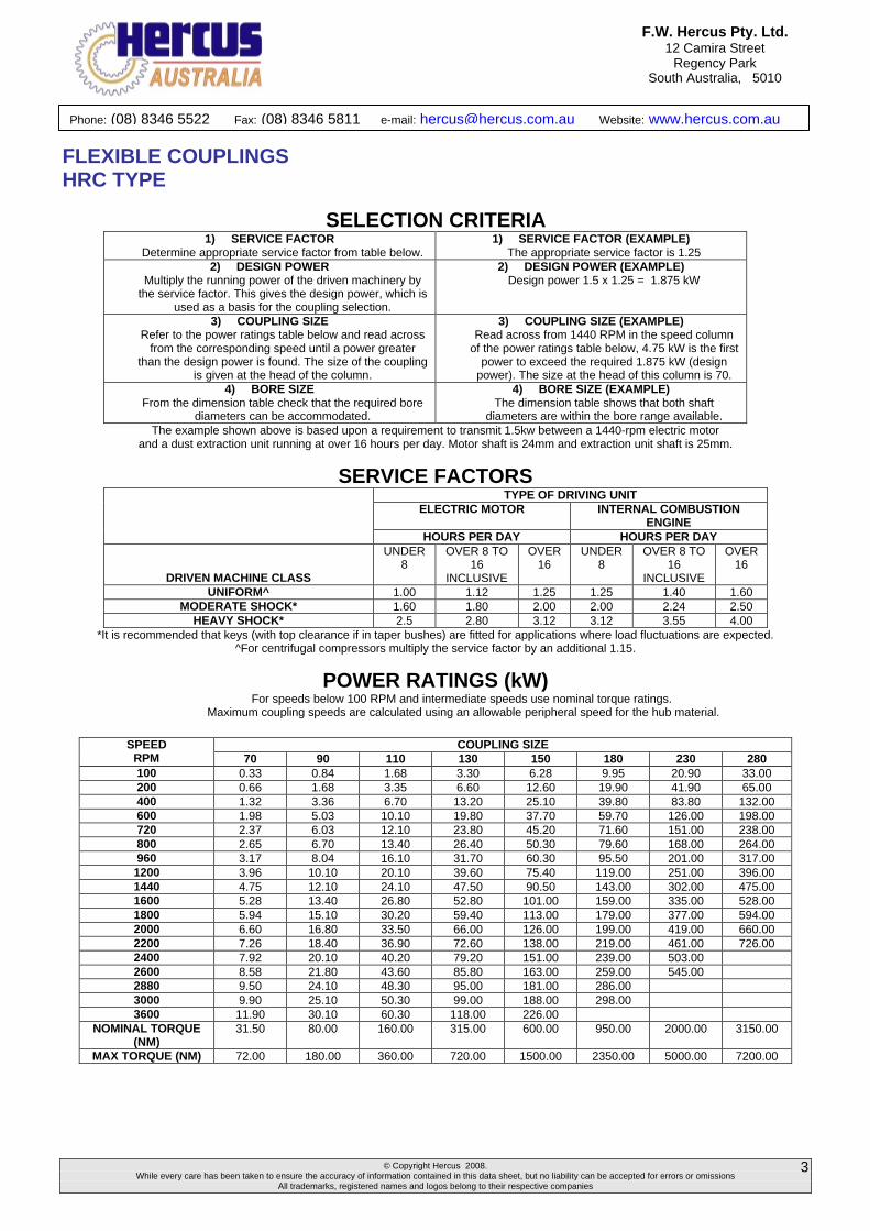
FLEXIBLE COUPLINGS HRC TYPE Hercus HRC Couplings are designed for general-purpose applications where the demand for a low cost, spacer type flexible coupling is required. Hercus HRC Couplings absorb shock loads, dampen small amplitude vibration and allow for incidental misalignment. Hercus HRC Couplings have integrally cast driving dogs to maintain a positive drive in the unlikely event of the flexible element being destroyed. With the addition of taper bushes Hercus HRC Couplings permit quick and easy assembly. Hercus HRC Couplings require no lubrication and are virtually maintenance free making them suitable for most environments. Hercus HRC finished bore with keyway.
DIMENSIONS COMMON DIMENSIONS TYPE F & H TYPE B
MAX BORE
BORE DIA
SIZE
OD
H
E
F
G
BUSH SIZE
MM INCHES C D J MAX PILOT
C
D
70 69 60 31 25 18 1008 25 1 20 23.5 29 32 10 20 25.8 90 85 70 32 30.5 22.5 1108 28 1.125 19.5 23.5 29 38 10 26 30 110 112 100 45 45 29 1610 42 1.625 18.5 26.5 38 55 10 37 45.3 130 130 105 50 54 36 1610 42 1.625 18 26.5 38 60 20 39 47.5 150 150 115 62 61 40 2012 50 2 23.5 33.5 42 70 28 46 60 180 180 125 77 74 49 2517 60 2.5 34.5 46.5 48 80 28 58 70 230 225 155 99 85.5 59.5 3020 75 3 39.5 52.5 55 100 45 77 90 280 275 206 119 105.5 74.5 3525 100 4 51 66.5 67 115 55 90 105.5
Dimensions in MM unless otherwise specified
ASSEMBLED DIMENSIONS AND SPECIFICATIONS Dimensions in MM unless otherwise specified
All Hercus HRC Couplings have an angular misalignment capacity of up to 1 degree Weight is for an FF, FH or HH coupling with mid range taper bush
ASSEMBLED LENGTH (L) MAX. MISALIGNMENT SIZE FF, FH, HH FB, HB BB
TORQUE Nm PARALLEL AXIAL
KG
70 65 65 65 70 0.3 +0.2 1
90 69.5 76 82.5 90 0.3 +0.5 1.17
110 82 100.5 119 110 0.3 +0.6 5
130 89 110 131 130 0.4 +0.8 5.46
150 107 129.5 152 150 0.4 +0.9 7.11
180 142 165.5 189 180 0.4 +1.1 16.6
230 164.5 202 239.5 230 0.5 +1.3 26
280 207.5 246.5 285.5 280 0.5 +1.7 50
© Copyright Hercus 2008. While every care has been taken to ensure the accuracy of information contained in this data sheet, but no liability can be accepted for errors or omissions
All trademarks, registered names and logos belong to their respective companies
3
Phone: (08) 8346 5522 Fax: (08) 8346 5811 e-mail: [email protected] Website: www.hercus.com.au
F.W. Hercus Pty. Ltd. 12 Camira Street
Regency Park South Australia, 5010
FLEXIBLE COUPLINGS HRC TYPE
SELECTION CRITERIA 1) SERVICE FACTOR
Determine appropriate service factor from table below. 1) SERVICE FACTOR (EXAMPLE)
The appropriate service factor is 1.25 2) DESIGN POWER
Multiply the running power of the driven machinery by the service factor. This gives the design power, which is
used as a basis for the coupling selection.
2) DESIGN POWER (EXAMPLE) Design power 1.5 x 1.25 = 1.875 kW
3) COUPLING SIZE Refer to the power ratings table below and read across
from the corresponding speed until a power greater than the design power is found. The size of the coupling
is given at the head of the column.
3) COUPLING SIZE (EXAMPLE) Read across from 1440 RPM in the speed column
of the power ratings table below, 4.75 kW is the first power to exceed the required 1.875 kW (design
power). The size at the head of this column is 70. 4) BORE SIZE
From the dimension table check that the required bore diameters can be accommodated.
4) BORE SIZE (EXAMPLE) The dimension table shows that both shaft
diameters are within the bore range available. The example shown above is based upon a requirement to transmit 1.5kw between a 1440-rpm electric motor
and a dust extraction unit running at over 16 hours per day. Motor shaft is 24mm and extraction unit shaft is 25mm.
SERVICE FACTORS TYPE OF DRIVING UNIT
ELECTRIC MOTOR INTERNAL COMBUSTION ENGINE
HOURS PER DAY HOURS PER DAY
DRIVEN MACHINE CLASS
UNDER 8
OVER 8 TO 16
INCLUSIVE
OVER 16
UNDER 8
OVER 8 TO 16
INCLUSIVE
OVER 16
UNIFORM^ 1.00 1.12 1.25 1.25 1.40 1.60 MODERATE SHOCK* 1.60 1.80 2.00 2.00 2.24 2.50
HEAVY SHOCK* 2.5 2.80 3.12 3.12 3.55 4.00 *It is recommended that keys (with top clearance if in taper bushes) are fitted for applications where load fluctuations are expected.
^For centrifugal compressors multiply the service factor by an additional 1.15.
POWER RATINGS (kW) For speeds below 100 RPM and intermediate speeds use nominal torque ratings.
Maximum coupling speeds are calculated using an allowable peripheral speed for the hub material.
COUPLING SIZE SPEED RPM 70 90 110 130 150 180 230 280 100 0.33 0.84 1.68 3.30 6.28 9.95 20.90 33.00 200 0.66 1.68 3.35 6.60 12.60 19.90 41.90 65.00 400 1.32 3.36 6.70 13.20 25.10 39.80 83.80 132.00 600 1.98 5.03 10.10 19.80 37.70 59.70 126.00 198.00 720 2.37 6.03 12.10 23.80 45.20 71.60 151.00 238.00 800 2.65 6.70 13.40 26.40 50.30 79.60 168.00 264.00 960 3.17 8.04 16.10 31.70 60.30 95.50 201.00 317.00 1200 3.96 10.10 20.10 39.60 75.40 119.00 251.00 396.00 1440 4.75 12.10 24.10 47.50 90.50 143.00 302.00 475.00 1600 5.28 13.40 26.80 52.80 101.00 159.00 335.00 528.00 1800 5.94 15.10 30.20 59.40 113.00 179.00 377.00 594.00 2000 6.60 16.80 33.50 66.00 126.00 199.00 419.00 660.00 2200 7.26 18.40 36.90 72.60 138.00 219.00 461.00 726.00 2400 7.92 20.10 40.20 79.20 151.00 239.00 503.00 2600 8.58 21.80 43.60 85.80 163.00 259.00 545.00 2880 9.50 24.10 48.30 95.00 181.00 286.00 3000 9.90 25.10 50.30 99.00 188.00 298.00 3600 11.90 30.10 60.30 118.00 226.00
NOMINAL TORQUE (NM)
31.50 80.00 160.00 315.00 600.00 950.00 2000.00 3150.00
MAX TORQUE (NM) 72.00 180.00 360.00 720.00 1500.00 2350.00 5000.00 7200.00

© Copyright Hercus 2008. While every care has been taken to ensure the accuracy of information contained in this data sheet, but no liability can be accepted for errors or omissions
All trademarks, registered names and logos belong to their respective companies
4
Phone: (08) 8346 5522 Fax: (08) 8346 5811 e-mail: [email protected] Website: www.hercus.com.au
F.W. Hercus Pty. Ltd. 12 Camira Street
Regency Park South Australia, 5010
FLEXIBLE COUPLINGS HRC TYPE
CATALOGUE CODES
HRC COUPLINGS
SIZE TYPE F TYPE H TYPE B (PILOT BORE) ELEMENTS 70 HRC-70F HRC-70H HRC-70B HRC-70SE 90 HRC-90F HRC-90H HRC-90B HRC-90SE 110 HRC-110F HRC-110H HRC-110B HRC-110SE 130 HRC-130F HRC-130H HRC-130B HRC-130SE 150 HRC-150F HRC-150H HRC-150B HRC-150SE 180 HRC-180F HRC-180H HRC-180B HRC-180SE 230 HRC-230F HRC-230H HRC-230B HRC-230SE 280 HRC-280F HRC-280H HRC-280B HRC-280SE.
TAPER BUSHES METRIC
BORE W X H
KEWAY CAT. CODE
1008 CAT. CODE
1108 CAT. CODE
1610 CAT. CODE
2012 CAT CODE
2517 CAT. CODE
3020 CAT. CODE
3525 10 3 1.4 TB1008 - 10MM TB1108 - 10MM xxx xxx Xxx xxx xxx 11 4 1.8 TB1008 - 11MM TB1108 - 11MM xxx xxx Xxx xxx xxx 12 4 1.8 TB1008 - 12MM TB1108 - 12MM xxx xxx Xxx xxx xxx 14 5 2.3 TB1008 - 14MM TB1108 - 14MM TB1610 - 14MM TB2012 - 14MM Xxx xxx xxx 15 5 2.3 xxx xxx TB1610 - 15MM TB2012 - 15MM Xxx xxx xxx 16 5 2.3 TB1008 - 16MM TB1108 - 16MM TB1610 - 16MM TB2012 - 16MM TB2517 – 16MM xxx xxx 17 5 2.3 TB1008 - 17MM xxx TB1610 - 17MM TB2012 - 17MM TB2517 – 17MM xxx xxx 18 6 2.8 TB1008 - 18MM TB1108 - 18MM TB1610 - 18MM TB2012 - 18MM TB2517 – 18MM xxx xxx 19 6 2.8 TB1008 - 19MM TB1108 - 19MM TB1610 - 19MM TB2012 - 19MM TB2517 – 19MM xxx xxx 20 6 2.8 TB1008 - 20MM TB1108 - 20MM TB1610 - 20MM TB2012 - 20MM TB2517 – 20MM xxx xxx 22 6 2.8 TB1008 - 22MM TB1108 - 22MM TB1610 - 22MM TB2012 - 22MM TB2517 – 22MM xxx xxx 23 6 2.8 xxx TB1108 - 23MM TB1610 - 23MM TB2012 - 23MM TB2517 – 23MM xxx xxx 24 8 3.3 TB1008 - 24MM TB1108 - 24MM TB1610 - 24MM TB2012 - 24MM TB2517 – 24MM xxx xxx 25 8 3.3 TB1008 - 25MM TB1108 - 25MM TB1610 - 25MM TB2012 - 25MM TB2517 – 25MM TB3020 - 25MM xxx 28 8 3.3 xxx TB1108 - 28MM TB1610 - 28MM TB2012 - 28MM TB2517 – 28MM TB3020 - 28MM xxx 30 8 3.3 xxx xxx TB1610 - 30MM TB2012 - 30MM TB2517 – 30MM TB3020 - 30MM xxx 32 10 3.3 xxx xxx TB1610 - 32MM TB2012 - 32MM TB2517 – 32MM TB3020 - 32MM xxx 35 10 3.3 xxx xxx TB1610 - 35MM TB2012 - 35MM TB2517 – 35MM TB3020 - 35MM TB3525 - 35MM 38 10 3.3 xxx xxx TB1610 - 38MM TB2012 - 38MM TB2517 – 38MM TB3020 - 38MM TB3525 - 38MM 40 12 3.3 xxx xxx TB1610 - 40MM TB2012 - 40MM TB2517 – 40MM TB3020 - 40MM TB3525 - 40MM 42 12 3.3 xxx xxx TB1610 - 42MM TB2012 - 42MM TB2517 – 42MM TB3020 - 42MM TB3525 - 42MM 45 14 3.8 xxx xxx xxx TB2012 - 45MM TB2517 – 45MM TB3020 - 45MM TB3525 - 45MM 48 14 3.8 xxx xxx xxx TB2012 - 48MM TB2517 – 48MM TB3020 - 48MM TB3525 - 48MM 50 14 3.8 xxx xxx xxx TB2012 - 50MM TB2517 – 50MM TB3020 - 50MM TB3525 - 50MM 55 16 4.3 xxx xxx xxx xxx TB2517 – 55MM TB3020 - 55MM TB3525 - 55MM 60 18 4.4 xxx xxx xxx xxx TB2517 – 60MM TB3020 - 60MM TB3525 - 60MM 65 18 4.4 xxx xxx xxx xxx Xxx TB3020 - 65MM TB3525 - 65MM 70 20 4.9 xxx xxx xxx xxx Xxx TB3020 - 70MM TB3525 - 70MM 75 20 4.9 xxx xxx xxx xxx Xxx TB3020 - 75MM TB3525 - 75MM 80 22 5.4 xxx xxx xxx xxx Xxx xxx TB3525 - 80MM 85 22 5.4 xxx xxx xxx xxx Xxx xxx TB3525 - 85MM 90 25 5.4 xxx xxx xxx xxx Xxx xxx TB3525 - 90MM 95 25 5.4 xxx xxx xxx xxx Xxx xxx TB3525 - 95MM 100 28 6.4 xxx xxx xxx xxx Xxx xxx TB3525 - 100MM
Dimensions in MM unless otherwise specified
© Copyright Hercus 2008. While every care has been taken to ensure the accuracy of information contained in this data sheet, but no liability can be accepted for errors or omissions
All trademarks, registered names and logos belong to their respective companies
5
Phone: (08) 8346 5522 Fax: (08) 8346 5811 e-mail: [email protected] Website: www.hercus.com.au
F.W. Hercus Pty. Ltd. 12 Camira Street
Regency Park South Australia, 5010
FLEXIBLE COUPLINGS HRC TYPE
TAPER BUSHES IMPERIAL
BORE W X H
KEYWAY CAT. CODE
1008 CAT. CODE
1108 CAT. CODE
1610 CAT. CODE
2012 CAT. CODE
2517 CAT. CODE
3020 CAT. CODE
3525 0.375 0.125 0.062 TB1008 - 3/8" TB1108 - 3/8" xxx xxx xxx xxx xxx 0.5 0.125 0.062 TB1008 - 1/2" TB1108 - 1/2" TB1610 - 1/2" xxx xxx xxx xxx
0.625 0.187 0.093 TB1008 - 5/8" TB1108 - 5/8" TB1610 - 5/8" TB2012 - 5/8" xxx xxx xxx 0.75 0.187 0.093 TB1008 - 3/4" TB1108 - 3/4" TB1610 - 3/4" TB2012 - 3/4" TB2517 - 3/4" xxx xxx 0.875 0.25 0.125 TB1008 - 7/8" TB1108 - 7/8" TB1610 - 7/8" TB2012 - 7/8" TB2517 - 7/8" xxx xxx
1 0.25 0.125 TB1008 - 1" TB1108 - 1" TB1610 - 1" TB2012 - 1" TB2517 - 1" xxx xxx 1.125 0.312 0.125 xxx TB1108 - 1-1/8" TB1610 - 1-1/8" TB2012 - 1-1/8" TB2517 - 1-1/8" xxx xxx 1.25 0.312 0.125 xxx xxx TB1610 - 1-1/4" TB2012 - 1-1/4" TB2517 - 1-1/4" TB3020 - 1-1/4" xxx 1.375 0.375 0.125 xxx xxx TB1610 - 1-3/8" TB2012 - 1-3/8" TB2517 - 1-3/8" TB3020 - 1-3/8" xxx 1.5 0.375 0.125 xxx xxx TB1610 - 1-1/2" TB2012 - 1-1/2" TB2517 - 1-1/2" TB3020 - 1-1/2" TB3525 - 1-1/2"
1.625 0.437 0.156 xxx xxx TB1610 - 1-5/8" TB2012 - 1-5/8" TB2517 - 1-5/8" TB3020 - 1-5/8" TB3525 - 1-5/8" 1.75 0.437 0.156 xxx xxx xxx TB2012 - 1-3/4" TB2517 - 1-3/4" TB3020 - 1-3/4" TB3525 - 1-3/4" 1.875 0.5 0.156 xxx xxx xxx TB2012 - 1-7/8" TB2517 - 1-7/8" TB3020 - 1-7/8" TB3525 - 1-7/8"
2 0.5 0.156 xxx xxx xxx TB2012 - 2" TB2517 - 2" TB3020 - 2" TB3525 - 2" 2.125 0.625 0.218 xxx xxx xxx xxx TB2517 - 2-1/8" TB3020 - 2-1/8" TB3525 - 2-1/8" 2.25 0.625 0.218 xxx xxx xxx xxx TB2517 - 2-1/4" TB3020 - 2-1/4" TB3525 - 2-1/4" 2.375 0.625 0.218 xxx xxx xxx xxx TB2517 - 1-3/8" TB3020 - 2-3/8" TB3525 - 2-3/8" 2.5 0.625 0.218 xxx xxx xxx xxx TB2517 - 2-1/2" TB3020 - 2-1/2" TB3525 - 2-1/2"
2.625 0.75 0.25 xxx xxx xxx xxx xxx TB3020 - 2-5/8" TB3525 - 2-5/8" 2.75 0.75 0.25 xxx xxx xxx xxx xxx TB3020 - 2-3/4" TB3020 - 2-3/4" 2.875 0.75 0.25 xxx xxx xxx xxx xxx TB3020 - 2-7/8" TB3525 - 2-7/8'
3 0.75 0.25 xxx xxx xxx xxx xxx TB3020 - 3" TB3525 - 3" 3.125 0.875 0.312 xxx xxx xxx xxx xxx xxx TB3525 - 3-1/8" 3.25 0.875 0.312 xxx xxx xxx xxx xxx xxx TB3525 - 3-1/4' 3.375 0.875 0.312 xxx xxx xxx xxx xxx xxx TB3525 - 3-3/8' 3.5 0.875 0.312 xxx xxx xxx xxx xxx xxx TB3525 - 3-1/2"
3.75 1 0.375 xxx xxx xxx xxx xxx xxx TB3525 - 3-3/4" 4 1 0.375 xxx xxx xxx xxx xxx xxx TB3525 - 4"
Dimensions in inches unless otherwise specified

© Copyright Hercus 2008. While every care has been taken to ensure the accuracy of information contained in this data sheet, but no liability can be accepted for errors or omissions
All trademarks, registered names and logos belong to their respective companies
6
Phone: (08) 8346 5522 Fax: (08) 8346 5811 e-mail: [email protected] Website: www.hercus.com.au
F.W. Hercus Pty. Ltd. 12 Camira Street
Regency Park South Australia, 5010
CHAIN SHAFT COUPLINGS Chain couplings are ideal where high static or starting loads apply. They are easily disconnected and are composed of two hardened steel sprockets connected by duplex roller chain. Each coupling is supplied complete with an aluminium alloy casing.
Chain Coupling Bore Dimensions Weight Dimensions Weight
Imperial Inches Inches Pounds Inches Pounds
Metric mm mm kg mm kg
Cat. No. Min. Max. A B C D E F
0.433” 0.866” 2.40” 1.38” 3.126” 1.42” 1.76 2.95” 2.95” 0.66 4012
11 22 61 35 79.4 36 0.8 75 75 0.3
0.591” 1.181” 3.03” 1.97” 3.126” 1.42” 3.09 3.62” 2.95” 0.88 4016
15 30 77 50 79.4 36 1.4 92 75 0.4
0.591” 1.496” 3.78” 2.36” 3.925” 1.77” 5.73 4.37” 3.35” 1.32 5016
15 38 96 60 99.7 45 2.6 111 85 0.6
0.748” 1.772” 4.17” 2.76” 3.925” 1.77” 7.72 4.80” 3.35” 1.76 5018
19 45 106 70 99.7 45 3.5 122 85 0.8
0.866” 2.165” 5.00” 3.35” 4.705” 2.13” 13.23 5.59” 4.17” 2.65 6018
22 55 127 85 119.5 54 6.0 142 106 1.2
0.984” 2.953” 5.95” 4.33” 4.705” 2.13” 20.94 6.58” 4.17” 3.53 6022
25 75 151 110 119.5 54 9.5 167 106 1.6
1.181” 3.071” 6.26” 4.53” 5.874” 2.64” 30.87 7.32” 5.12” 5.51 8018
30 78 159 115 149.2 67 14.0 186 130 2.5
1.378” 3.740” 7.95” 5.51” 5.874” 2.64” 44.09 8.66” 5.12” 5.95 8022
35 95 202 140 149.2 67 20.0 220 130 2.7
1.496” 4.331” 9.13” 6.30” 7.906” 3.58” 74.96 9.76” 5.67 6.61 10020
38 110 232 160 200.8 91 34.0 248 144 3.0 Dimensions in Inches and mm. Transmission Capacity (kw)
Cat
. No
.
Sh
aft
Dia
. Revolutions per Minute (RPM)
10 25 50 100 200 300 400 500 600 800 1000 1200 1500 1800 2000 2500 3000 3600 4000 4800 5200 6000
4012 22 0.22 0.58 1.15 1.73 2.63 3.46 4.15 4.96 5.67 7.01 8.53 9.68 11.6 13.7 14.8 17.9 20.7 24.1 26.3 30.8
4016 30 0.41 1.03 2.06 3.09 4.69 6.17 7.41 8.85 10.1 12.5 15.3 17.3 21.0 24.4 26.3 31.9 37.0 43.0 46.9 54.9
5016 38 0.78 1.95 3.91 5.86 8.92 11.7 14.1 16.8 19.2 23.8 28.9 32.9 39.9 46.4 50.0 60.6 70.4 81.6
5018 45 0.99 2.48 4.95 7.43 11.3 14.9 17.8 21.3 24.4 30.1 36.6 41.6 50.5 58.8 63.4 76.8 89.2
6018 55 1.87 4.67 9.33 14.0 21.3 28.0 33.6 40.1 45.9 56.8 69.1 78.4 95.2 111 120 145
6022 75 2.51 6.31 12.5 18.8 28.6 37.7 45.3 54.1 61.9 76.5 93.1 105 128 149 161 195
8018 78 4.14 10.3 20.7 31.0 47.2 62.1 74.5 89.0 101 126 153 174 211 246 265
8022 95 5.93 14.8 29.6 44.5 67.2 89.0 106 127 146 180 219 249 302 352 379
10020 110 9.33 23.3 46.6 70.0 106 140 168 200 229 283 345 392 476 554

© Copyright Hercus 2008. While every care has been taken to ensure the accuracy of information contained in this data sheet, but no liability can be accepted for errors or omissions
All trademarks, registered names and logos belong to their respective companies
7
Phone: (08) 8346 5522 Fax: (08) 8346 5811 e-mail: [email protected] Website: www.hercus.com.au
F.W. Hercus Pty. Ltd. 12 Camira Street
Regency Park South Australia, 5010
Q
R
T
G LJ K P P
'X' MOVEMENT TO DISENGAGE
AD CLUTCH
HUB 'D'
BODY 'A'
NMGKJ
R
T
Q V
P P
'X' MOVEMENT TO DISENGAGE
4 HOLES FOR'W' DIA. CAPSCREWS.
AF CLUTCH
BODY 'A'
HUB 'F'
SPLINE CLUTCHES These consist of two mating components with internal and external involute splines for clutch engagement. The leading edge of each spline is pointed to assist in the engagement, which should occur when the unit is stationary or rotating very slowly. The sliding component is the Body ‘A’ which has an operating groove in the outside diameter. This can be used with either a Plain Hub ‘D’ or Flanged Hub ‘F’. The clutches are made from mild steel and for more severe applications may be case hardened and tempered at 220ºC. The maximum torque, which can be transmitted by the clutch, is generally limited by the size of shaft and key used to drive it and the selection of clutch should normally be made on this basis.
Cat. No. Max. Bore G J K L M N P Q R T V W X
0.750” 0.375” 2.1/4” 1.5/8” 1.1/4” 2” 2.500” 1.1/4” 1.3/4” 3/8” 5/16” 1/2” 1/4” 3/8” SH 15
19 9.53 57.2 41.3 31.7 50.8 63.50 31.7 44.4 9.5 7.9 12.7 6.3 9.5
1.062” 0.625” 2.3/4” 2” 1.3/4” 2.5/8” 3.250” 1.1/2” 2.1/8” 7/16” 3/8” 5/8” 5/16” 1/2” SH 20
27 15.88 59.9 50.8 44.4 66.7 82.55 38.1 54.0 11.1 9.5 15.9 7.9 12.7
1.375” 0.750” 3.1/4” 2.1/2” 2.1/4” 3.1/4” 4.000” 1.3/4” 2.1/2” 1/2” 7/16” 3/4” 3/8” 5/8” SH 25
35 19.05 82.6 63.5 57.1 82.5 101.60 44.4 63.5 12.7 11.1 19.0 9.5 15.9
1.750” 1.000” 3.3/4” 3” 2.3/4” 3.3/4” 4.625” 2” 2.7/8” 9/16” 7/16” 7/8” 7/16” 3/4” SH 30
45 25.40 95.3 76.2 69.8 95.2 117.48 50.8 73.0 14.3 11.1 22.2 11.1 19.0
2.375” 1.250” 5” 4.1/4” 3.3/4” 5” 6” 2.3/4” 3.7/8” 5/8” 1/2” 1” 1/2” 7/8” SH 40
60 31.75 127 108 95 127 152.40 69.9 98.4 15.9 12.7 25.4 12.7 22.2
Dimensions in Inches and mm.
© Copyright Hercus 2008. While every care has been taken to ensure the accuracy of information contained in this data sheet, but no liability can be accepted for errors or omissions
All trademarks, registered names and logos belong to their respective companies
8
Phone: (08) 8346 5522 Fax: (08) 8346 5811 e-mail: [email protected] Website: www.hercus.com.au
F.W. Hercus Pty. Ltd. 12 Camira Street
Regency Park South Australia, 5010
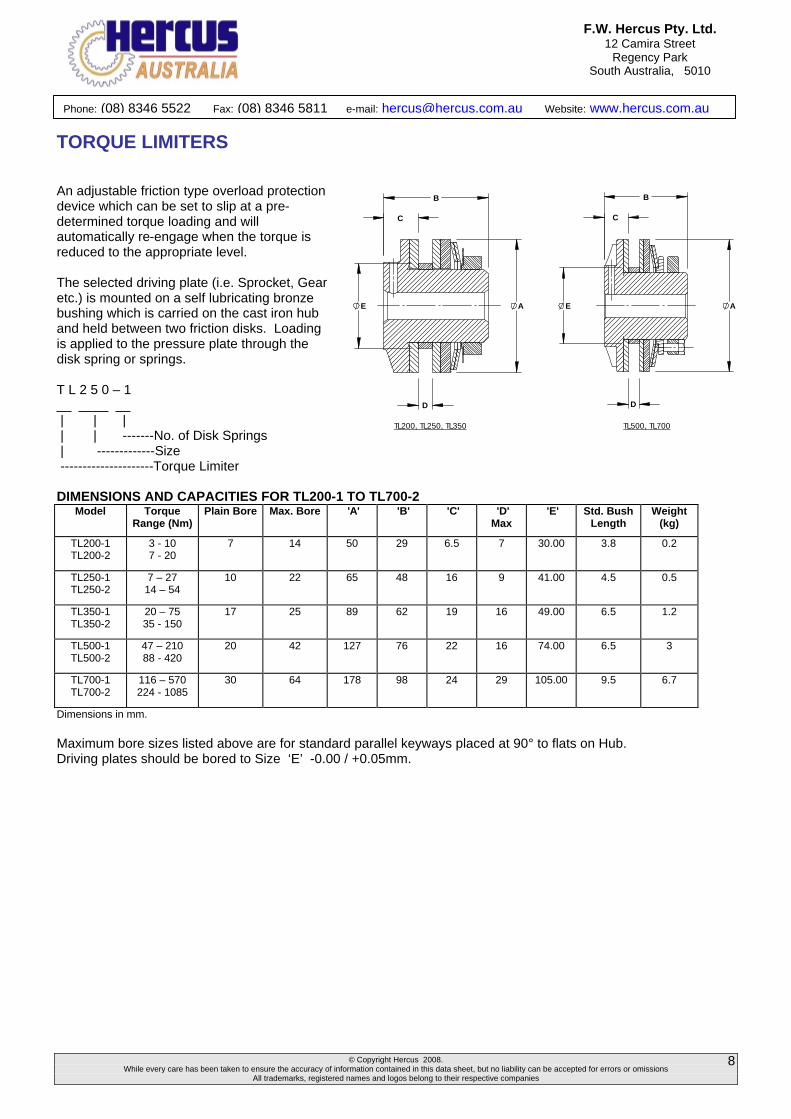
TORQUE LIMITERS An adjustable friction type overload protection device which can be set to slip at a pre-determined torque loading and will automatically re-engage when the torque is reduced to the appropriate level. The selected driving plate (i.e. Sprocket, Gear etc.) is mounted on a self lubricating bronze bushing which is carried on the cast iron hub and held between two friction disks. Loading is applied to the pressure plate through the disk spring or springs. T L 2 5 0 – 1 __ ____ __ | | | | | -------No. of Disk Springs | -------------Size ---------------------Torque Limiter DIMENSIONS AND CAPACITIES FOR TL200-1 TO TL700-2
Model Torque Range (Nm)
Plain Bore Max. Bore 'A' 'B' 'C' 'D' Max
'E' Std. Bush Length
Weight (kg)
TL200-1 TL200-2
3 - 10 7 - 20
7 14 50 29 6.5 7 30.00 3.8 0.2
TL250-1 TL250-2
7 – 27 14 – 54
10 22 65 48 16 9 41.00 4.5 0.5
TL350-1 TL350-2
20 – 75 35 - 150
17 25 89 62 19 16 49.00 6.5 1.2
TL500-1 TL500-2
47 – 210 88 - 420
20 42 127 76 22 16 74.00 6.5 3
TL700-1 TL700-2
116 – 570 224 - 1085
30 64 178 98 24 29 105.00 9.5 6.7
Dimensions in mm. Maximum bore sizes listed above are for standard parallel keyways placed at 90° to flats on Hub. Driving plates should be bored to Size ‘E’ -0.00 / +0.05mm.
A
B
C
E
D
TL200, TL250, TL350
AE
B
C
D
TL500, TL700
© Copyright Hercus 2008. While every care has been taken to ensure the accuracy of information contained in this data sheet, but no liability can be accepted for errors or omissions
All trademarks, registered names and logos belong to their respective companies
9
Phone: (08) 8346 5522 Fax: (08) 8346 5811 e-mail: [email protected] Website: www.hercus.com.au
F.W. Hercus Pty. Ltd. 12 Camira Street
Regency Park South Australia, 5010
TORQUE LIMITERS
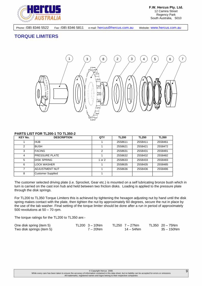
1 3 8 2 3 4 5 6 7
PARTS LIST FOR TL200-1 TO TL350-2
KEY No. DESCRIPTION QTY TL200 TL250 TL350
1 HUB 1 25S8611 25S8411 25S8461
2 BUSH 1 25S8621 25S8421 25S8472
3 FACING 2 25S8631 25S8431 25S8481
4 PRESSURE PLATE 1 25S8632 25S8432 25S8482
5 DISK SPRING 1 or 2 25S8633 25S8433 25S8483
6 LOCK WASHER 1 25S8635 25S8435 25S8485
7 ADJUSTMENT NUT 1 25S8636 25S8436 25S8486
8 Customer Supplied 1
The customer selected driving plate (i.e. Sprocket, Gear etc.) is mounted on a self lubricating bronze bush which in turn is carried on the cast iron hub and held between two friction disks. Loading is applied to the pressure plate through the disk springs. For TL200 to TL350 Torque Limiters this is achieved by tightening the hexagon adjusting nut by hand until the disk spring makes contact with the plate, then tighten the nut by approximately 60 degrees, secure the nut in place by the use of the tab washer. Final setting of the torque limiter should be done after a run in period of approximately 500 revolutions at 50 – 70 rpm. The torque ratings for the TL200 to TL350 are:- One disk spring (item 5) TL200 3 – 10Nm TL250 7 – 27Nm TL350 20 – 75Nm Two disk springs (item 5) 7 – 20Nm 14 – 54Nm 35 – 150Nm
© Copyright Hercus 2008. While every care has been taken to ensure the accuracy of information contained in this data sheet, but no liability can be accepted for errors or omissions
All trademarks, registered names and logos belong to their respective companies
10
Phone: (08) 8346 5522 Fax: (08) 8346 5811 e-mail: [email protected] Website: www.hercus.com.au
F.W. Hercus Pty. Ltd. 12 Camira Street
Regency Park South Australia, 5010
TORQUE LIMITERS
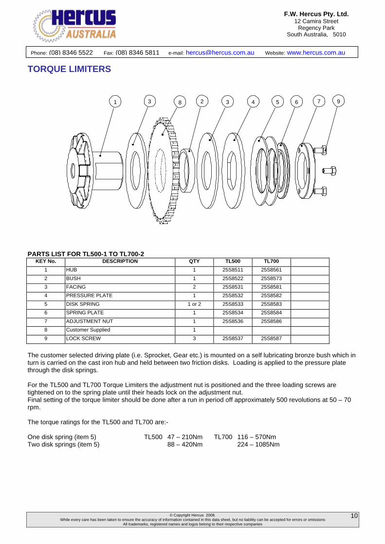
1 3 8 2 3 4 5 6 7 9
PARTS LIST FOR TL500-1 TO TL700-2
KEY No. DESCRIPTION QTY TL500 TL700
1 HUB 1 25S8511 25S8561
2 BUSH 1 25S8522 25S8573
3 FACING 2 25S8531 25S8581
4 PRESSURE PLATE 1 25S8532 25S8582
5 DISK SPRING 1 or 2 25S8533 25S8583
6 SPRING PLATE 1 25S8534 25S8584
7 ADJUSTMENT NUT 1 25S8536 25S8586
8 Customer Supplied 1
9 LOCK SCREW 3 25S8537 25S8587
The customer selected driving plate (i.e. Sprocket, Gear etc.) is mounted on a self lubricating bronze bush which in turn is carried on the cast iron hub and held between two friction disks. Loading is applied to the pressure plate through the disk springs. For the TL500 and TL700 Torque Limiters the adjustment nut is positioned and the three loading screws are tightened on to the spring plate until their heads lock on the adjustment nut. Final setting of the torque limiter should be done after a run in period off approximately 500 revolutions at 50 – 70 rpm. The torque ratings for the TL500 and TL700 are:- One disk spring (item 5) TL500 47 – 210Nm TL700 116 – 570Nm Two disk springs (item 5) 88 – 420Nm 224 – 1085Nm

© Copyright Hercus 2008. While every care has been taken to ensure the accuracy of information contained in this data sheet, but no liability can be accepted for errors or omissions
All trademarks, registered names and logos belong to their respective companies
11
Phone: (08) 8346 5522 Fax: (08) 8346 5811 e-mail: [email protected] Website: www.hercus.com.au
F.W. Hercus Pty. Ltd. 12 Camira Street
Regency Park South Australia, 5010
TORQUE LIMITER COUPLINGS These couplings combine the flexibility of a chain coupling with the overload protection features of the torque limiter. They are made up from a torque limiter fitted with a plate sprocket and a mating hub sprocket, hollowed out to clear the head of the torque limiter. The two sprockets are connected by duplex chain to form the coupling. T L 2 5 0 – 1 C __ ____ __ __ | | | | | | | ---Coupling Type | | -------No. of Disk Springs | - ------------Size ---------------------Torque Limiter DIMENSIONS AND CAPACITIES FOR TL200-1C TO TL700-2C
Plain Bore Max. Bore
Model Torque Range (Nm)
Max. Running Speed (RPM) Coupling
Half TL Half Coupling Half TL Half
Sprocket ‘A’ ‘B’ ‘C’ ‘D’ ‘E’ Weight (kg)
TL200-1C 3 – 10
TL200-2C 7 – 20
1200 8 7 31 14 RS-40-16T 50 29 76 24 55 1.0
TL250-1C 7 – 27
TL250-2C 14 – 54
1000 13 10 38 22 RS-40-22T 56 48 102 25 76 2.0
TL350-1C 20 – 75
TL350-2C 35 – 150
800 13 17 45 25 RS-50-24T 72 62 137 37 103 5.2
TL500-1C 47 – 210
TL500-2C 88 – 420
500 18 20 65 42 RS-60-28T 105 76 188 40 120 12.3
TL700-1C 116 – 570
TL700-2C 224 - 1085
400 23 30 90 64 RS-80-28T 150 98 251 66 168 31.0
Dimensions in mm. Maximum bore sizes listed above are for standard parallel keyways placed at 90° to flats on Hub.
AD B
E
BORE
TL500-C, TL700-C
C
A
E
C
BOREBD
TL200-C, TL250-C, TL350-C
© Copyright Hercus 2008. While every care has been taken to ensure the accuracy of information contained in this data sheet, but no liability can be accepted for errors or omissions
All trademarks, registered names and logos belong to their respective companies
12
Phone: (08) 8346 5522 Fax: (08) 8346 5811 e-mail: [email protected] Website: www.hercus.com.au
F.W. Hercus Pty. Ltd. 12 Camira Street
Regency Park South Australia, 5010
TORQUE LIMITER COUPLINGS
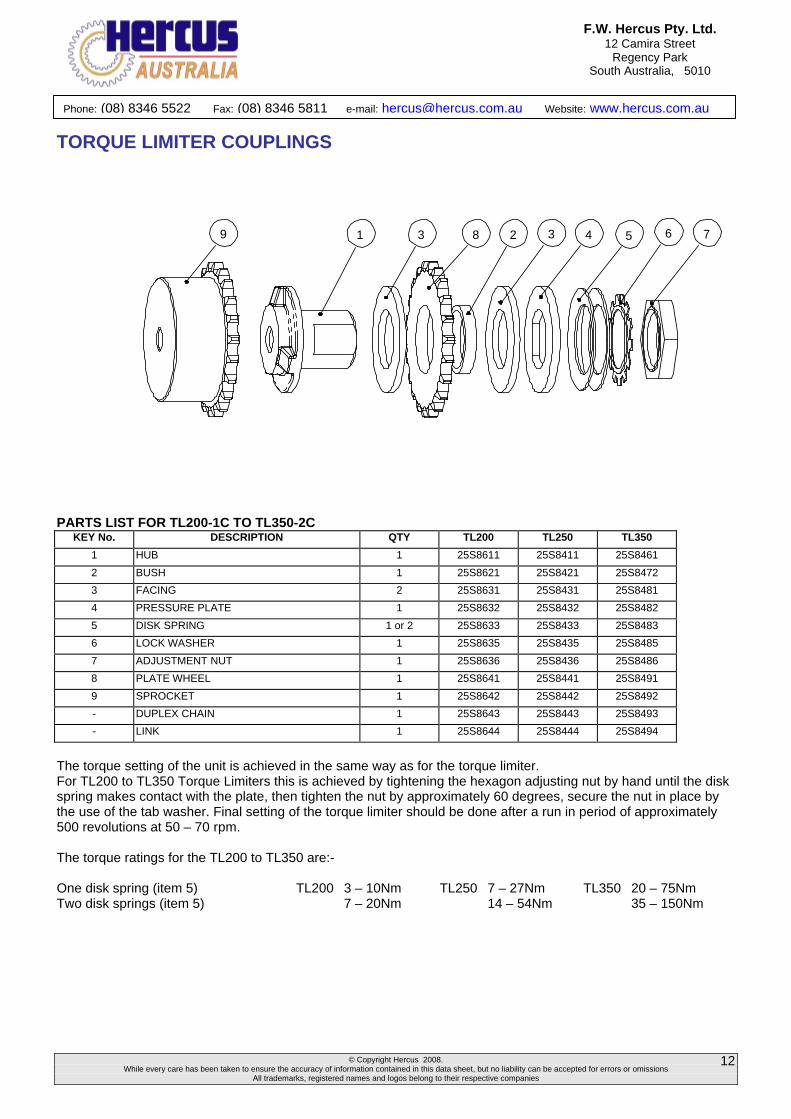
9 1 3 8 2 3 4 5 76
PARTS LIST FOR TL200-1C TO TL350-2C
KEY No. DESCRIPTION QTY TL200 TL250 TL350
1 HUB 1 25S8611 25S8411 25S8461
2 BUSH 1 25S8621 25S8421 25S8472
3 FACING 2 25S8631 25S8431 25S8481
4 PRESSURE PLATE 1 25S8632 25S8432 25S8482
5 DISK SPRING 1 or 2 25S8633 25S8433 25S8483
6 LOCK WASHER 1 25S8635 25S8435 25S8485
7 ADJUSTMENT NUT 1 25S8636 25S8436 25S8486
8 PLATE WHEEL 1 25S8641 25S8441 25S8491
9 SPROCKET 1 25S8642 25S8442 25S8492
- DUPLEX CHAIN 1 25S8643 25S8443 25S8493
- LINK 1 25S8644 25S8444 25S8494
The torque setting of the unit is achieved in the same way as for the torque limiter. For TL200 to TL350 Torque Limiters this is achieved by tightening the hexagon adjusting nut by hand until the disk spring makes contact with the plate, then tighten the nut by approximately 60 degrees, secure the nut in place by the use of the tab washer. Final setting of the torque limiter should be done after a run in period of approximately 500 revolutions at 50 – 70 rpm. The torque ratings for the TL200 to TL350 are:- One disk spring (item 5) TL200 3 – 10Nm TL250 7 – 27Nm TL350 20 – 75Nm Two disk springs (item 5) 7 – 20Nm 14 – 54Nm 35 – 150Nm
© Copyright Hercus 2008. While every care has been taken to ensure the accuracy of information contained in this data sheet, but no liability can be accepted for errors or omissions
All trademarks, registered names and logos belong to their respective companies
13
Phone: (08) 8346 5522 Fax: (08) 8346 5811 e-mail: [email protected] Website: www.hercus.com.au
F.W. Hercus Pty. Ltd. 12 Camira Street
Regency Park South Australia, 5010
TORQUE LIMITER COUPLINGS
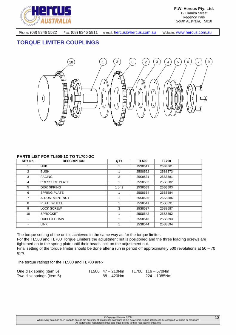
10 1 3 8 2 3 4 5 6 7 9
PARTS LIST FOR TL500-1C TO TL700-2C
KEY No. DESCRIPTION QTY TL500 TL700
1 HUB 1 25S8511 25S8561
2 BUSH 1 25S8522 25S8573
3 FACING 2 25S8531 25S8581
4 PRESSURE PLATE 1 25S8532 25S8582
5 DISK SPRING 1 or 2 25S8533 25S8583
6 SPRING PLATE 1 25S8534 25S8584
7 ADJUSTMENT NUT 1 25S8536 25S8586
8 PLATE WHEEL 1 25S8541 25S8591
9 LOCK SCREW 3 25S8537 25S8587
10 SPROCKET 1 25S8542 25S8592
- DUPLEX CHAIN 1 25S8543 25S8593
- LINK 1 25S8544 25S8594
The torque setting of the unit is achieved in the same way as for the torque limiter. For the TL500 and TL700 Torque Limiters the adjustment nut is positioned and the three loading screws are tightened on to the spring plate until their heads lock on the adjustment nut. Final setting of the torque limiter should be done after a run in period off approximately 500 revolutions at 50 – 70 rpm. The torque ratings for the TL500 and TL700 are:- One disk spring (item 5) TL500 47 – 210Nm TL700 116 – 570Nm Two disk springs (item 5) 88 – 420Nm 224 – 1085Nm