autodesk design review 2009 - dscohn.com design review.pdfautodesk ® design review 2009 ... design...
TRANSCRIPT

Autodesk® Design Review 2009 Project Drawing and File Collaboration Made Easy
David Cohn S1-6
Course Summary:
Do you need to exchange drawings and collaborate with others who don’t use AutoCAD? Creating and tracking revisions on projects is a daunting task. In this session, you’ll learn how to publish AutoCAD drawings as multi-sheet DWF files and then collaborate using Autodesk Design Review. We’ll cover creating DWF files; using Autodesk Design Review to view, measure, and mark up those DWF files; and then use AutoCAD’s Markup Set Manager to view and respond to those markups in a seamless collaboration process. Forget all that red-lined paper. Now you can track and manage your mark-ups electronically.
Instructor: David has more than 20 years of hands-on experience with AutoCAD as a user, developer, author and consultant. He is an applications engineer with The PPI Group, a contributing editor to Desktop Engineering magazine, the former publisher and editor-in-chief of CADCAMNet and Engineering Automation Report, the former senior editor of CADalyst magazine, and the author of more than a dozen books on AutoCAD. A licensed architect, David was also one of the earliest AutoCAD third-party software developers, creating numerous AutoCAD add-on programs. As an industry consultant, David has worked with many companies including Autodesk. He teaches college-level AutoCAD courses and is always a popular presenter at Autodesk University.
Autodesk User Group International
www.AUGI.com

Autodesk User Group International
www.AUGI.com Copyright © AUGI CAD Camp 2008
2
Introduction AutoCAD can export (plot or publish) drawing files in a special format called Design Web Format (DWF). This capability was first introduced as an add-on to AutoCAD Release 14. Later releases incorporated this capability as a basic function of AutoCAD.
The DWF file format has changed over the years. Initially, DWF files were 2D only and contained a single sheet. You could think of 2D DWF files as the electronic version of plot files: they contained an intelligent image of your drawing, not the drawing itself. More recently, Autodesk introduced 3D DWF files and enabled DWF files to contain multiple sheets. A single DWF file can contain both 2D and 3D data, and DWF files published from Inventor can also include animations and bills of materials.
For viewing and markup of DWF files, Autodesk provides Autodesk Design Review, which adds measure and markup capabilities, persistent 3D measure and markup, and drawing version comparison. In addition, when Design Review is run on computers with integrated GPS, field workers receive instant feedback on their location and the locations of specific assets.
DWF files offer several advantages over other methods of saving and viewing drawings: • Accurate: DWF files contain vector or solid information. When you zoom in to increase the
magnification, the image continues to display as vectors or solids. • Fast: The DWF format is highly compressed, so DWF files are smaller and faster to transmit
than DWG files. • Smart: The DWF format supports multisheet files, so you can publish an entire design set as
a single DWF file. Plus, when you create hyperlinks in your drawing and then create a DWF file, those hyperlinks are included in the DWF file.
• Safe: The DWF file does not expose the original AutoCAD DWG file. This means that you can publish your drawings to the Web in DWF format, while maintaining the ownership of the intellectual property contained in the DWG file
You can publish a DWF file from any AutoCAD 2004 or newer product by using the PUBLISH command. You can also plot a DWF file from any AutoCAD 2002 product. You can publish a DWF file from Inventor. You can export a 2D or 3D DWF file from Revit. You can also use the free DWF Writer application to create a DWF file from many other CAD programs or indeed from any other Windows program. But most significantly for today’s discussion, you can view, markup, and print DWF files, including “round-tripping” of markups and annotations, using Autodesk Design Review.
Autodesk used to deliver a free DWF Viewer product in addition to the “for-pay” Autodesk Design Review. Starting with the release of Design Review 2008, Autodesk made Design Review free and dropped the previous DWF Viewer product. Autodesk also provides two other free viewer products, DWG TrueView (viewing, printing, and plotting of DWG and DXF files plus publishing to DWF) and Autodesk Inventor View (viewing and plotting of Inventor files). The capabilities of these various products are summarized below:

Autodesk User Group International
www.AUGI.com Copyright © AUGI CAD Camp 2008
3
File Support
Autodesk Design Review
DWG TrueView
Autodesk Inventor View
Multisheet DWF files ● 3D DWF files ● DWG files ●1 ● DXF files ●1 ● Autodesk Inventor IPT, IAM, and IDW files ●2 ● Raster image files ● Features
Zoom, pan, navigate sheets or models ● ● ● View properties ● ● Turn layers or views on or off ● ● Plot files ● ● ● Print to large format or standard sheet sizes ● ● Publish files to DWF ● ● Measure ● Redline and annotate ● Track review status ● Integrate markups with Autodesk design software ●
1. DWG/DXF files can be imported and converted to DWF using Autodesk DWG TrueView.
2. After IPT, IAM, and IDW have been published to DWF using Autodesk Inventor View
Autodesk also collaborated with Microsoft to seamlessly integrate DWF technology with Windows Vista using the XML Paper Specification (XPS). This provides users with the ability to view and manage DWF design information without requiring additional downloads of plug-ins or special viewing software. DWF files published to the XPS specification can be automatically opened and viewed directly in Windows Vista using the XPS Viewer.
In addition, Autodesk Freewheel (http://freewheel.autodesk.com) is both a web site where you can open a DWF file for interactive viewing and a web service that allows you to embed an interactive viewer in your own web pages.
There are also several companion products that can help maximize the capabilities of Autodesk Design Review:
Batch Print Plug-in with HP Instant Printing – lets you send multiple DWF files at once when connected to an HP large-format printer

Autodesk User Group International
www.AUGI.com Copyright © AUGI CAD Camp 2008
4
Autodesk DWF Writer – creates DWF files from any Windows application, including Microsoft Office applications, or utilize DWF Writer plug-ins for SolidWorks, Pro/ENGINEER, and CATIA. JT Plug-in for Autodesk Design Review – import and publish JT files, a common UGS format, to DWF. DGN Plug-in for Autodesk Design Review – import and publish DGN files, a common MicroStation format, to DWF.
These software components and plug-ins are available for download from the Autodesk web site at www.autodesk.com/dwf-plugins.
In some ways, DWF files are similar to PDF. Like DWF, PDF files can contain multiple sheets and can contain the same information that would otherwise appear in a plotted drawing. But DWF files have many advantages over PDF, particularly for those who need to interact with CAD files that originate in an Autodesk product. In addition, the DWF file of an AutoCAD drawing will always be smaller than a PDF file created from the same drawing—approximately 1/20th the size of the original AutoCAD DWG file.
What is Autodesk Design Review? Autodesk Design Review (formerly known as DWF Composer) is a computer program created by Autodesk to enable team members and clients to review and markup design information even if they do not own or know how to use sophisticated software such as AutoCAD. It supports the electronic exchange of drawings and markups among participants via the Internet, an intranet, or by using physical media such as disks. After review and markup in Design Review, drawings can be sent back to the original designer for response to the markups. The exchange can continue until all issues are resolved and the original designer revises the drawings. Once you have a drawing or sheet set in DWF format, you can:
View • View a single drawing sheet or various sheets within a multi-sheet set • View 2D models, named views, and layouts • View flat 2D layouts created from 3D models • View 3D models saved as 3D DWF files • View the dimensions of a drawing • Follow hyperlinks within a set • Turn layers on and off • View object properties in a drawing • Navigate to various markups and keep track of the author, time of creation, current status,
and team discussion notes

Autodesk User Group International
www.AUGI.com Copyright © AUGI CAD Camp 2008
5
Markup • Markup a drawing sheet with markup comments, text, drawings, dimensions, and stamps • Respond to markups • Change the status of markups • Measure, section, and pull apart 3D models • Save snapshots of anything on screen as a 2D DWF sheet • Exchange discussion notes with others about a markup
Republish • Reorganize and recombine different drawing sheets into a set • Save drawing sheets with their markups • Print drawings with or without markups • Distribute drawings for further review • Save drawings directly to Buzzsaw • Embed drawings on a web site • Return drawing sheets to the originating designer to be read in Design Review, or if the
original drawing came from AutoCAD (2005 or later), Revit, or Inventor (v11 or later), to be read by the originating CAD system, from which the markups can then be responded to and returned to you.
What gets written to a DWF file? A 2D DWF file is truly an electronic version of a plot file. When you publish the DWF file, AutoCAD uses the same paper size, rotation, scale, and pen assignments determined by the page setup, just as when plotting to any other device. Only those layers that are visible, actually contain data, and set to plot are written to the DWF file. In addition, the DWF file contains all the linetype, lineweight, and color settings in effect when you publish the DWF file. Once the DWF file is created, you can use the tools in Design Review to display a particular sheet, turn selected layers on and off, or pan and zoom, just as with an AutoCAD drawing. You can also snap to geometry in the DWF file just as you can in AutoCAD, and take accurate measurements. Any hyperlinks contained in the original drawing are retained and remain active in the resulting DWF file. External references are also preserved.
• Raster Images – Raster images are stored in the DWF file • Named Views – Any named views in the original DWG file are saved to the resulting DWF file • Layers – Any layers that are visible in the DWG file, except those marked as not to be plotted,
are saved to the resulting DWF file, unless you specify that layer information is not to be included • Blocks – Individual blocks, along with any attribute data, are saved to the resulting DWF file,
unless you specify that block information is not to be included • Fonts – SHX font geometry is converted to simple vectors. TrueType fonts, except those
standard in Windows, are recorded within the DWF file so that fonts display properly within the resulting DWF file even if it contains fonts not loaded on the recipient’s computer

Autodesk User Group International
www.AUGI.com Copyright © AUGI CAD Camp 2008
6
Creating DWF files in AutoCAD There are two methods for creating DWF files in AutoCAD (depending on the type of file you require):
• Click PUBLISH (on the Output tab) to create a 2D DWF file. • Click EXPORT (on the Output tab) to create a 3D DWF file.
To publish a 2D DWF file (an electronic drawing set):
1. Start the PUBLISH command. 2. In the Publish dialog box, adjust the Sheets to Publish list as
necessary to add, remove, or reorder the sheets to be plotted. 3. Under Publish to, select DWF file. 4. Click Publish Options and use the controls in this dialog box to
specify where to save the DWF file, whether to publish an XPS-compatible or standard DXF file, whether the file is to be a single-sheet or multi-sheet DWF, whether to prompt for the name of the DWF file, whether to password protect the DWF file, whether layer information should be included, and whether block information should be included. Click OK when finished. (Note that if you password protect the DWF file, the recipient will need to enter this password in order to be able to open the DWF file. Passwords are case-sensitive and can consist of letters, numbers, punctuation, and non-ASCII characters. If you lose or forget the password, it cannot be recovered.)
5. Click Publish to start the electronic drawing set creation. When the DWF file has been created, AutoCAD informs you using the Plot and Publish status bar icon and alert balloon.
Note that you can also publish a sheet set directly from AutoCAD’s Sheet Set Manager.
Note: If you added sheets to the list of drawing sheets and have not yet saved the list, AutoCAD asks you if you want to save the current list of sheets. If you save the list (as a DSD—Drawing Set Description—file), you can easily republish the same collection of sheets again later after the drawings have been updated. Plot stamp information can also be included within published DWF files.
Controlling DWF Properties You can control many of the properties of DWF files—such as the resolution, format, background color, and inclusion of layer information—by changing the DWF plotter configuration. The PUBLISH command uses the DWF6 ePlot.pc3 or DWFx ePlot (XPS Compatible.pc3) plotter configuration file. All changes to the DWF properties are made from the Plot Properties dialog box, which can be accessed from the Plotter Configuration Editor. The Plotter Configuration Editor can be accessed by either selecting the DWF plotter configuration in the Page Setup Manager dialog box, or by opening the plotter configuration using the Plotter Manager. In the Plotter Configuration Editor, select Custom Properties and then click the Custom Properties button.

Autodesk User Group International
www.AUGI.com Copyright © AUGI CAD Camp 2008
7
Controlling Resolution You can specify the resolution for vector and raster graphics. Higher resolutions produce more precise DWF files at the expense of larger file sizes. The default value for vectors is 1200dpi. You can set separate values for color and black and white raster images. If you are creating DWF files intended for plotting, select a resolution to match the output of your plotter or printer. High resolutions (over 2400dpi) are for viewing. If you are creating a DWF file of a drawing with lots of detail, such as a large topographic map, using a higher resolution will enable you to zoom in to view finer detail. Resolutions over 40,000dpi may produce very large files. As you increase the resolution setting, the speed of printing decreases and memory requirements increase.
Controlling Font Handling You can control the inclusion and handling of TrueType fonts in DWF files:
• Capture none – No fonts are included in the DWF file. In order for fonts to be visible in the resulting DWF file, the fonts must be present on the system on which the DWF file is being viewed. If a particular font used in the DWF file isn’t present, another font will be substituted (which can sometimes produce undesired results).
• Capture some – The fonts used in the source drawing for the DWF file that are specified in the Available TrueType Fonts dialog box (displayed by clicking the Edit Font List button) will be included in the DWF file and therefore don’t need to be available on the DWF viewer’s system in order for them to appear in the DWF file. This is the recommended setting.
• Capture all – Specifies that all fonts used in the drawing will be included in the DWF file. (Note that if you select this option and also select All as Geometry, the fonts used in the drawing will be included as vector geometry rather than as text.)
Controlling Additional Output Settings The controls in the lower portion of the DWF Properties dialog box enable you to control other DWF properties, such as the file format (compressed binary or a ZIP encoded ASCII stream that can be unzipped), the background color (for example, to match the background of the DWF file to that of a web page), including layer information (this can also be controlled from the Publish Options dialog), and saving a preview image within the DWF file (this only needs to be selected if the recipient of the DWF file will use Buzzsaw.com to access the preview).
Note: The controls in the plotter Properties dialog box are slightly different for the DWF6 ePlot configuration compared to the DWFx ePlot configuration. Specifically, you cannot control font handling, DWF compression format, or preview image in XPS-compatible DWF files.

Autodesk User Group International
www.AUGI.com Copyright © AUGI CAD Camp 2008
8
Using Autodesk Design Review Once you have created a DWF file, you can use it to collaborate with someone who doesn’t actually own a copy of AutoCAD; all that person needs is a copy of Autodesk Design Review. For example, you can send a copy of the DWF file via email to your collaboration partner. When he or she receives your DWF file, your collaboration partner can open the file in Design Review and use the Design Review tools to view, measure, and markup the DWF file. When your collaboration partner has finished reviewing and marking up the DWF file, he or she can resave the DWF file and return it to you. You can then open the DWF file in AutoCAD using the Markup Set Manager. When you open the DWF file in AutoCAD, you can view all of the markup comments added by your collaboration partner, make the required changes to the AutoCAD drawing file, and if necessary save the DWF file again and send it back to your collaboration partner for further review.
The Autodesk Design Review Interface
The Autodesk Design Review 2009 interface consists of the components shown below: 1. Menu Bar 2. Main toolbar 3. Animation toolbar 4. Palette title bar 5. Palette 6. Canvas toolbar 7. Canvas 8. ViewCube

Autodesk User Group International
www.AUGI.com Copyright © AUGI CAD Camp 2008
9
The toolbars allow you to perform the most common actions in Design Review. The tools available in the toolbars will vary depending on the type of content you are viewing. Some toolbars (such as the Map toolbar) are conditional toolbars; they only appear when specific types of content (such as a georeferenced map) is visible on the canvas.
A palette is a group of related features that enables you to find and display information about content in a DWF file. Palettes can be manipulated to facilitate your design review sessions. Palettes can be docked (unpinned and pinned), undocked, and grouped. A docked palette is one that is attached to the program window and is constantly available in a workspace. Palettes can be docked in the docking areas above or below, and to the left or right of the canvas. By default, a docked palette is unpinned, meaning that the palette remains displayed at its current size and can be moved. When you pin a palette and move the mouse pointer away from it, the palette is reduced to a tab displaying just the palette name. Moving the mouse pointer over the tab displays the palette fully, but temporarily, over the canvas. Pinning a palette shows more of the canvas while still keeping the palette available. Pinning a palette also prevents it from being undocked, grouped, or ungrouped.
An undocked palette is one that has been separated from the program window. Each undocked palette can be moved around the screen or screens as desired. Although undocked palettes cannot be pinned, they can be resized and grouped.
A palette group is a way to have more than one palette occupy the same amount of space on the screen. When palettes are grouped, each palette is represented by a tab at the bottom of the group. For example, the Thumbnails and List View palettes are grouped by default. In a group, click a tab to display that palette. You can group or ungroup palettes as necessary and save custom workspaces to facilitate your design review process. After changing palette and toolbar positions, you can save your settings as a custom workspace (by choosing Window>Workspace>Save Current Workspace).
There are several palettes:
Contents: Thumbnails and List View – In previous versions of Design Review, the Contents palette had two different views: Thumbnails and List View. This has now been replaced by the Thumbnails and List View palettes, which display the 2D and 3D sheets, tables, and other sheets contained in the open DWF file. Click a sheet in either palette to display its contents on the canvas.
Properties: Sheet, Markup and Object – In previous versions of Design Review, the Properties palette had three different views: Sheet, Markup, and Object Properties. This has now been replaced by the Sheet Properties, Markup Properties, and Object Properties palettes. For the selected content, these three palettes, show sheet, markup, and object properties.

Autodesk User Group International
www.AUGI.com Copyright © AUGI CAD Camp 2008
10
Markup – lists all markups in the DWF file, organized by sheet. Clicking a markup displays it on the canvas and displays its markup properties in the Markup Properties palette.
Layers – displays a list of layer names. If layers were included in the DWF file, you can right-click on a layer to turn the layer on and off or click on its light bulb icon.
Cross Sections – displays a list of cross sections for 3D models. Right-clicking on a cross section enables you to perform various functions, such as renaming the cross section, flipping the cross section, hiding the cross section plane, deactivating the cross section, and so on.
Model – lists objects and sub-objects in a 3D model in a hierarchical arrangement, which indicates how they are assembled. Clicking an object or sub-object highlights it on the canvas.
Views – lists Standard views (3D views such as front, back, top, bottom, and so on) as well as views created in Design Review, AutoCAD, Inventor, and Revit.
Text Data – displays textual data, such as assembly instructions, included with published animations in a 3D DWF file.
Grid Data – displays any tabular data, such as a parts list or Bill of Materials, included in a DWF file.
Working with Autodesk Design Review
The currently selected sheet or model appears in the Canvas. Design Review can only have one DWF file open at a time and can only display one sheet or model view within that DWF file at a time. But you can open several copies of Design Review at the same time. Once you have two copies of Design Review open, you can:
• Open the same DWF file in all of them to try different markup options or to view different sheets in the same DWF file.
• Open different DWF files in each one to complement information provided by each. • Cut and paste markups between them to save time on repetitive markups (including
comments, stand-alone text, redline drawings, dimensions, and stamps), or • Drag and drop sheets between them to create custom DWF files
Most commands can be accessed using either the menus or toolbars. The tools available in toolbars vary depending on whether the sheet currently in the canvas is 2D or 3D. You can also perform numerous tasks in Design Review by using shortcut menus that appear when you right-click.
You can turn individual toolbars on and off using these shortcut menus. Toolbars can also be repositioned within the toolbar area, but cannot be undocked or moved from the toolbars area.
Autodesk User Group International
www.AUGI.com Copyright © AUGI CAD Camp 2008
11
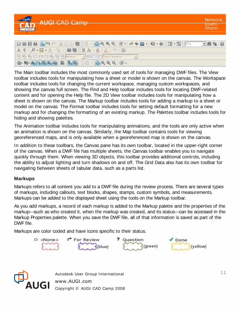
The Main toolbar includes the most commonly used set of tools for managing DWF files. The View toolbar includes tools for manipulating how a sheet or model is shown on the canvas. The Workspace toolbar includes tools for changing the current workspace, managing custom workspaces, and showing the canvas full screen. The Find and Help toolbar includes tools for locating DWF-related content and for opening the Help file. The 2D View toolbar includes tools for manipulating how a sheet is shown on the canvas. The Markup toolbar includes tools for adding a markup to a sheet or model on the canvas. The Format toolbar includes tools for setting default formatting for a new markup and for changing the formatting of an existing markup. The Palettes toolbar includes tools for hiding and showing palettes.
The Animation toolbar includes tools for manipulating animations, and the tools are only active when an animation is shown on the canvas. Similarly, the Map toolbar contains tools for viewing georeferenced maps, and is only available when a georeferenced map is shown on the canvas.
In addition to these toolbars, the Canvas pane has its own toolbar, located in the upper-right corner of the canvas. When a DWF file has multiple sheets, the Canvas toolbar enables you to navigate quickly through them. When viewing 3D objects, this toolbar provides additional controls, including the ability to adjust lighting and turn shadows on and off. The Grid Data also has its own toolbar for navigating between sheets of tabular data, such as a parts list.
Markups
Markups refers to all content you add to a DWF file during the review process. There are several types of markups, including callouts, text blocks, shapes, stamps, custom symbols, and measurements. Markups can be added to the displayed sheet using the tools on the Markup toolbar.
As you add markups, a record of each markup is added to the Markup palette and the properties of the markup—such as who created it, when the markup was created, and its status—can be accessed in the Markup Properties palette. When you save the DWF file, all of that information is saved as part of the DWF file.
Markups are color coded and have icons specific to their status.

Autodesk User Group International
www.AUGI.com Copyright © AUGI CAD Camp 2008
12
Hyperlinks
If the DWF file includes hyperlinks, you can navigate to those links. You can also control whether hyperlinks require you to press Ctrl+click or just simply click.
Other Functions in Design Review
You can move or delete markup objects, view or hide markups (using View>Show>Markups), view or hide hyperlinks, change colors, and so on. You can use the Contents palette to change the order of sheets within the DWF file. As already mentioned, you can open multiple instances of Design Review and copy and paste sheets between them. In the case of raster images, you can also drag and drop from Windows Explorer directly into Design Review. Note that you can also import DWG and DXF files, which first creates a DWF file and then opens it in Design Review as a new DWF file.
You can also print the DWF file to any Windows system printer. When printing, you can print the current sheet or all sheets in the DWF file. You can also scale the drawing to fit the sheet size or print it to scale, with large drawings tiled to fit onto multiple sheets (when the selected printer doesn’t support the sheet size).
There’s also a Batch Print wizard that lets you print multiple DWF files in a batch operation. You can control the print settings for each DWF file within multi-sheet DWF files and save those settings for reuse. If your computer is connected to an HP printer with Instant Printing capabilities, you can take advantage of a partnership between Autodesk and HP to provide a one-click method of printing called HP Instant Printing (HPIP) from the standard or batch print options.

Autodesk User Group International
www.AUGI.com Copyright © AUGI CAD Camp 2008
13
Republishing
Once you have annotated a DWF file, you can republish the DWF file. Typically, republishing means saving the DWF file so that it includes all the markups you’ve added. You can then send the DWF file back to its creator so that he or she can make changes to the original drawing to reflect the markups.
You can share the DWF file with anyone who has a computer and the necessary software to view the DWF file. While this can include someone else using Design Review, the most significant situation involves sending the DWF file back to the person who created the original DWF file from an AutoCAD DWG file (or someone using Inventor or Revit).
If the DWF file was created in any software in the AutoCAD family of products (2005 version or later), you can return it directly to the original author to automatically realign your markups with the original DWG file. In order for the DWF markup to align with the original DWG, the receiver must have the original DWG.
Using the Markup Set Manager DWF files containing markups can be opened in AutoCAD using the Markup Set Manager. The Markup Set Manager is available in all versions of AutoCAD beginning with AutoCAD 2005. Beginning in AutoCAD 2007, you can also insert DWF files as an underlay, but in order to work with the markups, you need to open the DWF file using the Markup Set Manager.
When the original designer opens your markup, the drawing, along with your markup, will zoom and pan to the view last current when you created the markup. The DWG author will see your markup comments and any other markup you created (redline drawing, dimensions, text blocks, or stamps). He or she can then respond to your comments and exchange information with you until all issues are resolved. You can change the markup status inside AutoCAD, but you cannot alter the markup itself.
When the DWF and aligned DWG are displayed in AutoCAD, you can toggle redline geometry on and off and toggle between DWF and DWG geometry.
After making any required changes to the drawing, you can republish all the sheets or just the marked-up sheets, and send the DWF file back to Design Review. You can repeat this process as many times as needed without any loss of data.
• Changing the order of sheets in Design Review does not affect their layout order in AutoCAD, but the new order is displayed in the Markup Set Manager and will be applied if you republish the DWF file.

Autodesk User Group International
www.AUGI.com Copyright © AUGI CAD Camp 2008
14
• If the original DWF file includes sheets from multiple DWG files, AutoCAD opens those drawings when you open those sheets.
• If you add new sheets in Design Review and then attempt to open them in AutoCAD, the DWF file opens in Design Review instead.
Advanced Design Review Functionality There are a number of additional features in Design Review to help you leverage the power of DWF.
Stamps and Custom Symbols
In addition to marking up 2D DWF files with notes, revision clouds, and graphics such as lines, arcs, and circles, you can add stamps such as Approved, Rejected, Not to Scale, and so on. Stamps are found on the Stamps flyout on the Markup toolbar.
You can also import any 2D DWF file as a symbol, using the tools in the Custom Symbols flyout on the Markup toolbar. The imported items become a catalog available from the Symbols flyout. If the DWF file being imported as a symbol includes block information, the individual blocks in that file can be imported as separate symbols, which then appear within a symbol catalog. By default, the catalog assumes the name of the imported DWF file and the individual symbols take on the original block names. You can then insert the individual blocks as symbols within other DWF files. Optionally, you can import each entire sheet in a DWF file as a symbol.
Once a symbol has been placed on a sheet, it appears in the Design Review Markups palette for tracking the symbol. If you place several copies of the same symbol on a sheet, they will be numbered consecutively, for example Chair 1, Chair 2, and so on. Note that the size of the symbol is determined by its size when the DWF file containing it was created. This, in turn, is controlled by the page setup in AutoCAD. Once a symbol has been inserted, it can be resized and rotated just like any other markup. And if you subsequently use AutoCAD’s Markup Set Manager to open a marked up DWF file containing symbols, the symbols all appear as part of the DWF file.

Autodesk User Group International
www.AUGI.com Copyright © AUGI CAD Camp 2008
15
Measurement and Persistent 3D Markup
DWF files support both 2D and 3D, and both 2D and 3D content can exist in a single DWF file. When you view a 3D model, you can change its shading; hide, show, and isolate individual parts; and view physical properties of individual parts (such as area, volume, mass, and center of gravity).
You can also measure distances between points, edges, center points, or any combination of these; the angle between edges; and the radii of arcs and circles. The units used are determined by the Display Units chosen for the open sheet. As you move the pointer over the model, Design Review highlights any points or edges. You simply click to select what’s highlighted. You can then drag and click where you want to place the measurement. The measurement may consist of a line or lines, arrowheads, a label with text, and a background color. When you create a measurement, its lines, arrowheads, lineweight, font size, and font color are determined by the format settings in effect at the time the measurement is created, but can be changed afterwards, if necessary. The resulting measurement is added to the Markups palette.
These 3D markups are saved as part of the DWF file and the markups will even reorient as you orbit around the 3D model.
Snapshot Tool
You can take a screen capture, or snapshot, of anything on your screen, inside or outside of the Design Center window. The Snapshot tool creates a new 2D sheet that is added to the current DWF file.

Autodesk User Group International
www.AUGI.com Copyright © AUGI CAD Camp 2008
16
When you click the Snapshot button, Design Review displays a capture window (a red border with its own small toolbar below). Drag the toolbar to reposition the window and drag the red border to resize the capture window. When you are ready to capture the image, click the camera icon on the capture window toolbar. The captured image is added to the current DWF file and appears in the Thumbnails and List View palettes. To close the window without capturing anything, click the red X.
Moving and Rotating 3D Parts
When working with 3D models, you can select one or more parts in an assembly and use the Move and Rotate tool to move or rotate the selected parts along or about an axis, or within a plane defined by any two axes. To restore a single part to its original position, with the Move and Rotate tool selected double-click the part in the Canvas, or right-click the part in the Model palette and select Reset from the shortcut menu. To move all the parts back to their original position, right-click the ViewCube and choose Starting View, right-click the top-level assembly in the Model palette and select Reset, or with the top-level assembly selected click the Palette Options button and choose Reset.

Autodesk User Group International
www.AUGI.com Copyright © AUGI CAD Camp 2008
17
Creating Cross Sections
You can also create cross sections by cutting through the model with a section plane. You can then manipulate the view by moving or rotating the section plane. Design Review lets you create section planes aligned with any of the three axial pairs or aligned with a surface. Each section plane you create is added to the Cross Sections palette, and all of the sections are initially active—in other words, the model appears to be cut by all of the planes. You can then use controls in the Cross Section palette to flip any of the planes, hide them so that you don’t see the plane itself, or make any of the planes active or inactive. When inactive, the model is no longer shown cut by that particular plane. You can also reorient the model so that it is viewed normal to a section plane, reset a section plane to its original position, or delete a section plane. Section planes are initially numbered in the order in which they were created, but you can rename the planes within the Cross Sections palette.
Drawing Version Compare
You can compare 2D DWF files and vector content to understand what has changed between versions. To do so, you open one DWF file and then select Tools > Compare to open the Compare dialog. Browse to select the DWF file you want to use for comparison and then select the sheet you wish to compare to the sheet currently in the canvas.
Note that this compare function may sometimes produce unexpected results. For example, Design Review will identify all differences between two DWF files regardless of whether those differences were made intentionally by the reviewer or unintentionally by an anomaly in a publishing program.

Autodesk User Group International
www.AUGI.com Copyright © AUGI CAD Camp 2008
18
Design Review is also unable to compare vector (shape) and raster (pixel) content, a common publishing error that occurs when a 2D DWF file is published from a 3D model space.
Online Content Search
You can use Design Review to search online product and part catalogs hosted by Thomas Publishing and Global Spec for a selected part’s description, title, or part number.
Georeferenced Maps
Sheets with defined latitude and longitude coordinates published from AutoCAD Map 3D or AutoCAD Civil 3D (2008 versions or later) can interact with GPS devices that use the NMEA 0183 protocol. When a georeferenced map is displayed on the canvas, the Map toolbar is displayed directly below the canvas. To view published map coordinates, move the mouse pointer over the map. The current coordinates of the mouse pointer are shown on the Map toolbar. Note that to identify your current location, you must also be connected to a GPS device.
Navigation and Visualization Tools
The ViewCube and navigation wheels that are now a standard feature in other Autodesk software first appeared in Design Review 2008. When viewing a 2D sheet, you can use the new 2D navigation Steering Wheel to pan or zoom within the sheet. When viewing a 3D sheet, you have a choice of three different Object Wheels. The View Object Wheel contains tools that are commonly used when
Autodesk User Group International
www.AUGI.com Copyright © AUGI CAD Camp 2008
19
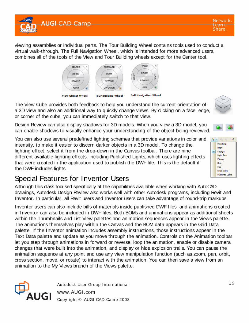
viewing assemblies or individual parts. The Tour Building Wheel contains tools used to conduct a virtual walk-through. The Full Navigation Wheel, which is intended for more advanced users, combines all of the tools of the View and Tour Building wheels except for the Center tool.
The View Cube provides both feedback to help you understand the current orientation of a 3D view and also an additional way to quickly change views. By clicking on a face, edge, or corner of the cube, you can immediately switch to that view.
Design Review can also display shadows for 3D models. When you view a 3D model, you can enable shadows to visually enhance your understanding of the object being reviewed.
You can also use several predefined lighting schemes that provide variations in color and intensity, to make it easier to discern darker objects in a 3D model. To change the lighting effect, select it from the drop-down in the Canvas toolbar. There are nine different available lighting effects, including Published Lights, which uses lighting effects that were created in the application used to publish the DWF file. This is the default if the DWF includes lights.
Special Features for Inventor Users Although this class focused specifically at the capabilities available when working with AutoCAD drawings, Autodesk Design Review also works well with other Autodesk programs, including Revit and Inventor. In particular, all Revit users and Inventor users can take advantage of round-trip markups.
Inventor users can also include bills of materials inside published DWF files, and animations created in Inventor can also be included in DWF files. Both BOMs and animations appear as additional sheets within the Thumbnails and List View palettes and animation sequences appear in the Views palette. The animations themselves play within the Canvas and the BOM data appears in the Grid Data palette. If the Inventor animation includes assembly instructions, those instructions appear in the Text Data palette and update as you move through the animation. Controls on the Animation toolbar let you step through animations in forward or reverse, loop the animation, enable or disable camera changes that were built into the animation, and display or hide explosion trails. You can pause the animation sequence at any point and use any view manipulation function (such as zoom, pan, orbit, cross section, move, or rotate) to interact with the animation. You can then save a view from an animation to the My Views branch of the Views palette.

Autodesk User Group International
www.AUGI.com Copyright © AUGI CAD Camp 2008
20
Inventor users also have the option of disabling functions in DWF files published from Inventor. For example, measurement, markup, and printing can be disabled for some or all sheets in the published DWF file.
Conclusion While DWF is unlikely to completely supplant PDF, it offers numerous advantages, particularly for users of Autodesk software. DWF files are almost always smaller than comparable PDF files. The tools for creating DWF files are free, either included as standard features of Autodesk’s other programs or by using the free DWF Writer. Tools for simply viewing DWF files are also free—Autodesk Freewheel provides a great way for anyone to view DWF files as well as for embedding DWF files into web pages. And users can “round-trip” DWF files, such as from AutoCAD to Design Review and subsequently back to AutoCAD, without any loss of data.
The combination of AutoCAD and Autodesk Design Review makes it easy to exchange CAD data electronically, mark up that data, and return those markups to the original CAD program, repeatedly. DWF files are also used by Autodesk FM Desktop.
DWF is a powerful collaboration format, and Autodesk is likely to continue to leverage the power of DWF even more in the future.