autodesk topobase user s guide - autodesk | 3d design
TRANSCRIPT

Autodesk® Topobase™ Web User’s Guide
Autodesk® Topobase™ WebUser’s Guide
© 2009 Autodesk, Inc. All Rights Reserved. Except as otherwise permitted by Autodesk, Inc., this publication, or parts thereof, may not bereproduced in any form, by any method, for any purpose. Certain materials included in this publication are reprinted with the permission of the copyright holder. TrademarksThe following are registered trademarks or trademarks of Autodesk, Inc., in the USA and other countries: 3DEC (design/logo), 3December,3December.com, 3ds Max, ADI, Alias, Alias (swirl design/logo), AliasStudio, Alias|Wavefront (design/logo), ATC, AUGI, AutoCAD, AutoCADLearning Assistance, AutoCAD LT, AutoCAD Simulator, AutoCAD SQL Extension, AutoCAD SQL Interface, Autodesk, Autodesk Envision, AutodeskInsight, Autodesk Intent, Autodesk Inventor, Autodesk Map, Autodesk MapGuide, Autodesk Streamline, AutoLISP, AutoSnap, AutoSketch,AutoTrack, Backdraft, Built with ObjectARX (logo), Burn, Buzzsaw, CAiCE, Can You Imagine, Character Studio, Cinestream, Civil 3D, Cleaner,Cleaner Central, ClearScale, Colour Warper, Combustion, Communication Specification, Constructware, Content Explorer, Create>what's>Next>(design/logo), Dancing Baby (image), DesignCenter, Design Doctor, Designer's Toolkit, DesignKids, DesignProf, DesignServer, DesignStudio,Design|Studio (design/logo), Design Web Format, Discreet, DWF, DWG, DWG (logo), DWG Extreme, DWG TrueConvert, DWG TrueView, DXF,Ecotect, Exposure, Extending the Design Team, Face Robot, FBX, Filmbox, Fire, Flame, Flint, FMDesktop, Freewheel, Frost, GDX Driver, Gmax,Green Building Studio, Heads-up Design, Heidi, HumanIK, IDEA Server, i-drop, ImageModeler, iMOUT, Incinerator, Inferno, Inventor, InventorLT, Kaydara, Kaydara (design/logo), Kynapse, Kynogon, LandXplorer, LocationLogic, Lustre, Matchmover, Maya, Mechanical Desktop, Moonbox,MotionBuilder, Movimento, Mudbox, NavisWorks, ObjectARX, ObjectDBX, Open Reality, Opticore, Opticore Opus, PolarSnap, PortfolioWall,Powered with Autodesk Technology, Productstream, ProjectPoint, ProMaterials, RasterDWG, Reactor, RealDWG, Real-time Roto, REALVIZ,Recognize, Render Queue, Retimer,Reveal, Revit, Showcase, ShowMotion, SketchBook, Smoke, Softimage, Softimage|XSI (design/logo),SteeringWheels, Stitcher, Stone, StudioTools, Topobase, Toxik, TrustedDWG, ViewCube, Visual, Visual Construction, Visual Drainage, VisualLandscape, Visual Survey, Visual Toolbox, Visual LISP, Voice Reality, Volo, Vtour, Wire, Wiretap, WiretapCentral, XSI, and XSI (design/logo). The following are registered trademarks or trademarks of Autodesk Canada Co. in the USA and/or Canada and other countries:Backburner,Multi-Master Editing, River, and Sparks. The following are registered trademarks or trademarks of MoldflowCorp. in the USA and/or other countries: Moldflow, MPA, MPA(design/logo),Moldflow Plastics Advisers, MPI, MPI (design/logo), Moldflow Plastics Insight,MPX, MPX (design/logo), Moldflow Plastics Xpert. All other brand names, product names or trademarks belong to their respective holders. DisclaimerTHIS PUBLICATION AND THE INFORMATION CONTAINED HEREIN IS MADE AVAILABLE BY AUTODESK, INC. "AS IS." AUTODESK, INC. DISCLAIMSALL WARRANTIES, EITHER EXPRESS OR IMPLIED, INCLUDING BUT NOT LIMITED TO ANY IMPLIED WARRANTIES OF MERCHANTABILITY ORFITNESS FOR A PARTICULAR PURPOSE REGARDING THESE MATERIALS. Published by:Autodesk, Inc.111 Mclnnis ParkwaySan Rafael, CA 94903, USA

Contents
Chapter 1 Topobase Web User Guide . . . . . . . . . . . . . . . . . . . . . 1Introduction . . . . . . . . . . . . . . . . . . . . . . . . . . . . . . . . 1Starting Topobase Web . . . . . . . . . . . . . . . . . . . . . . . . . . . 3Using Topobase Web . . . . . . . . . . . . . . . . . . . . . . . . . . . . 4
Navigating in Topobase Web . . . . . . . . . . . . . . . . . . . . . 4Using a Basic Layout . . . . . . . . . . . . . . . . . . . . . . 4Using a Flexible Fusion Layout . . . . . . . . . . . . . . . . . 7Using Document Explorer . . . . . . . . . . . . . . . . . . 12Using Display Models . . . . . . . . . . . . . . . . . . . . . 13Using Workflow Explorer . . . . . . . . . . . . . . . . . . . 14Using Electric Explorer . . . . . . . . . . . . . . . . . . . . 15
Using Specialized Modules . . . . . . . . . . . . . . . . . . . . . 16Using Topobase Wastewater . . . . . . . . . . . . . . . . . . 16Using Topobase Electric . . . . . . . . . . . . . . . . . . . . 18Using Topobase Gas . . . . . . . . . . . . . . . . . . . . . . 18Using Topobase Water . . . . . . . . . . . . . . . . . . . . . 19
Finding Features in Your Map . . . . . . . . . . . . . . . . . . . . 20Using Position Finder . . . . . . . . . . . . . . . . . . . . . 21
Using Markup Functions . . . . . . . . . . . . . . . . . . . . . . 22Redlining . . . . . . . . . . . . . . . . . . . . . . . . . . . 22Dimensioning . . . . . . . . . . . . . . . . . . . . . . . . . 23
Reporting and Sharing . . . . . . . . . . . . . . . . . . . . . . . 24Using the Plot Library . . . . . . . . . . . . . . . . . . . . . 24Printing Reports . . . . . . . . . . . . . . . . . . . . . . . . 26
iii
Creating Polygon/Line Definition Reports . . . . . . . . . . 27Exporting Feature Data . . . . . . . . . . . . . . . . . . . . 27
Creating and Editing . . . . . . . . . . . . . . . . . . . . . . . . 29Creating Features . . . . . . . . . . . . . . . . . . . . . . . 29Editing Feature Information . . . . . . . . . . . . . . . . . 30Using Templates . . . . . . . . . . . . . . . . . . . . . . . . 30Construction and Calculation . . . . . . . . . . . . . . . . 32Deleting Features . . . . . . . . . . . . . . . . . . . . . . . 32Splitting Lines . . . . . . . . . . . . . . . . . . . . . . . . . 33Adding Labels . . . . . . . . . . . . . . . . . . . . . . . . . 33Performing Intersections . . . . . . . . . . . . . . . . . . . 34Using Data Checker . . . . . . . . . . . . . . . . . . . . . . 34
Using Feature Class Forms . . . . . . . . . . . . . . . . . . . . . . . . 35Using the Feature Class Form Toolbar . . . . . . . . . . . . . . . 35Updating Records Globally . . . . . . . . . . . . . . . . . . . . . 36Adding Data Using Reference Records . . . . . . . . . . . . . . . 37Filtering Data in Feature Class Forms . . . . . . . . . . . . . . . . 38
Filtering Techniques . . . . . . . . . . . . . . . . . . . . . . 38Filter Expressions . . . . . . . . . . . . . . . . . . . . . . . 39Saving and Reusing Filters . . . . . . . . . . . . . . . . . . 40Spatial Selection . . . . . . . . . . . . . . . . . . . . . . . . 41Filtering Related Records . . . . . . . . . . . . . . . . . . . 42
Setting Topobase Web Options . . . . . . . . . . . . . . . . . . . . . . 42Setting Application Options . . . . . . . . . . . . . . . . . . . . 42
Setting Job Options . . . . . . . . . . . . . . . . . . . . . . 43Setting Map Options . . . . . . . . . . . . . . . . . . . . . 43Setting COGO Options . . . . . . . . . . . . . . . . . . . . 44
Setting Document Options . . . . . . . . . . . . . . . . . . . . . 45Setting COGO and Dimensioning Document
Options . . . . . . . . . . . . . . . . . . . . . . . . . . . 46Setting Wastewater Document Options . . . . . . . . . . . 47Setting Electric Explorer Document Options . . . . . . . . . 47
Chapter 2 Using Jobs in Topobase Web . . . . . . . . . . . . . . . . . . . 49Navigating Topobase Jobs . . . . . . . . . . . . . . . . . . . . . . . . . 49
Using the Job Control . . . . . . . . . . . . . . . . . . . . . . . . 49Using Job Explorer . . . . . . . . . . . . . . . . . . . . . . . . . 50Using Job Manager . . . . . . . . . . . . . . . . . . . . . . . . . 51
Understanding the Job Workflow . . . . . . . . . . . . . . . . . . . . . 52Creating a Job . . . . . . . . . . . . . . . . . . . . . . . . . . . . 53Defining the Job Perimeter . . . . . . . . . . . . . . . . . . . . . 53Selecting a Job . . . . . . . . . . . . . . . . . . . . . . . . . . . . 54Undoing Modifications in Jobs . . . . . . . . . . . . . . . . . . . 56Changing the Job State (Job Transition) . . . . . . . . . . . . . . 57Managing Job Conflicts . . . . . . . . . . . . . . . . . . . . . . . 58Creating a Historical Job View . . . . . . . . . . . . . . . . . . . 60
iv | Contents
Leasing a Job . . . . . . . . . . . . . . . . . . . . . . . . . . . . 60
Chapter 3 Working with Topologies . . . . . . . . . . . . . . . . . . . . . 63Area Topologies and Logical Topologies . . . . . . . . . . . . . . . . . 63Checking Area Topologies . . . . . . . . . . . . . . . . . . . . . . . . . 64Checking Logical Topologies . . . . . . . . . . . . . . . . . . . . . . . 66Analyzing Network Topologies . . . . . . . . . . . . . . . . . . . . . . 67Managing Logical Connections . . . . . . . . . . . . . . . . . . . . . . 70
Chapter 4 Construction and Calculation . . . . . . . . . . . . . . . . . . . 73Using Construction Tools . . . . . . . . . . . . . . . . . . . . . . . . . 73Construction Reference . . . . . . . . . . . . . . . . . . . . . . . . . . 74
Construction Toolbar . . . . . . . . . . . . . . . . . . . . . . . . 74Navigating the Construction Commands . . . . . . . . . . . . . 76
Construction: General Guidelines . . . . . . . . . . . . . . 76Construction Dialog Boxes and Menus . . . . . . . . . . . . 76
Constructions: Intersection . . . . . . . . . . . . . . . . . . . . . 78Intersection Elements . . . . . . . . . . . . . . . . . . . . . 79Intersection Workflow . . . . . . . . . . . . . . . . . . . . 81
Constructions: Arc Intersection . . . . . . . . . . . . . . . . . . . 82Arc Intersection Elements . . . . . . . . . . . . . . . . . . . 83Arc Intersection Workflow . . . . . . . . . . . . . . . . . . 84
Constructions: Orthogonal Calculation . . . . . . . . . . . . . . 85Orthogonal Calculation Elements . . . . . . . . . . . . . . 86Orthogonal Calculation Workflow . . . . . . . . . . . . . . 88
Constructions: Polar Calculation . . . . . . . . . . . . . . . . . . 89Polar Calculation Elements . . . . . . . . . . . . . . . . . . 90Polar Calculation Workflow . . . . . . . . . . . . . . . . . . 92
Constructions: Orthogonal Projection . . . . . . . . . . . . . . . 92Orthogonal Projection Elements . . . . . . . . . . . . . . . 93Orthogonal Projection Workflow . . . . . . . . . . . . . . . 94
Constructions: Snap and Trim . . . . . . . . . . . . . . . . . . . 95Snap and Trim Elements . . . . . . . . . . . . . . . . . . . 95Snap and Trim Workflow . . . . . . . . . . . . . . . . . . . 97
Constructions: Offset (Line Calculation) . . . . . . . . . . . . . . 97Line Offset Calculation Elements . . . . . . . . . . . . . . . 98Line Offset Calculation Workflow . . . . . . . . . . . . . . 99
Constructions: Line Processing (Vertices) . . . . . . . . . . . . . . 99Line Processing Workflows (Vertices) . . . . . . . . . . . . 100
Constructions: Line Processing (Points) . . . . . . . . . . . . . . 103Constructions: Insert Point . . . . . . . . . . . . . . . . . 104Constructions: Extract Point . . . . . . . . . . . . . . . . 106
Constructions: Right Angle Course . . . . . . . . . . . . . . . . 107Right Angle Course Elements . . . . . . . . . . . . . . . . 108Right Angle Course Workflow . . . . . . . . . . . . . . . . 109
Contents | v

Constructions: Join Lines . . . . . . . . . . . . . . . . . . . . . 110Join Lines Workflow . . . . . . . . . . . . . . . . . . . . . 110
Constructions: Free Standpoint . . . . . . . . . . . . . . . . . . 111Free Standpoint Elements . . . . . . . . . . . . . . . . . . 111Free Standpoint Workflow . . . . . . . . . . . . . . . . . . 113
Constructions: Center . . . . . . . . . . . . . . . . . . . . . . . 113Center Elements . . . . . . . . . . . . . . . . . . . . . . . 113Center Workflow . . . . . . . . . . . . . . . . . . . . . . . 114
Constructions: Reports . . . . . . . . . . . . . . . . . . . . . . . 114Constructions: Tips and Tricks . . . . . . . . . . . . . . . . . . . 115
Chapter 5 Glossary . . . . . . . . . . . . . . . . . . . . . . . . . . . . . 117
Index . . . . . . . . . . . . . . . . . . . . . . . . . . . . . . . 123
vi | Contents
Topobase Web User Guide
IntroductionUse Autodesk Topobase Web to work with Topobase project data in a webbrowser.
Your administrator configures Topobase Web to make a set of its functionsavailable. You may be able to view and search only, or you may be able to usemuch of the functionality available in Topobase Client.
NOTE If your browser blocks content, the help will not display. Be sure to selectAllow Blocked Content.
Topobase Web Functions
Topobase Web supports the following functions:
Viewing functions:
■ Finding a location in the map (page 21)
■ Spatial Selection (page 41)
■ Filtering Data in Feature Class Forms (page 38)
Markup functions:
■ Redlining (page 22)
■ Adding dimension or orthogonal marking lines (page 23)
1
1
Reporting and sharing functions:
■ Plotting a map (page 24)
■ Generating Polygon/Line reports (page 27)
■ Exporting feature data (page 27)
Feature creation and editing functions:
■ Creating data and geometry (page 29)
■ Viewing and editing feature data (page 30)
■ Using templates (page 30)
■ Using construction and calculation (COGO) tools (page 32)
■ Deleting features (page 32)
■ Splitting lines (page 33)
■ Creating labels (page 33)
■ Performing intersections (page 34)
■ Using Topobase acquisition and analysis workflows for maintainingconsistency when creating and editing features (page 14)
Job and validation functions:
■ Using Topobase jobs for managing versions
■ Using Data Checker (page 34)
The administrator defines display models, styles and themes. You do not needto generate graphics. To update the display, refresh the map.
For information about configuring and administering Topobase Web, see the“Topobase Administrators Guide” and “Topobase Installation andConfiguration Guide.”
About Autodesk MapGuide Viewer
Topobase Web is integrated into the Autodesk MapGuide Viewer. Use anyoperation available with the MapGuide Viewer:
■ Zoom in and out
2 | Chapter 1 Topobase Web User Guide

■ Pan
■ Measure distances
■ Create buffer zones around features
■ Select features in several ways
■ Print the map (including redlines).
For more information, see the MapGuide Viewer help.
About Viewers and Layouts
Topobase uses the AJAX viewer, which requires no extra client software.
Administrators can configure Topobase to use flexible layouts (page 7) (basedon Fusion) or basic layouts (page 4). Each layout has a distinctive look andfeel.
For information about building web layouts, see the Autodesk MapGuide®
Studio help.
NOTE Administrators: Topobase Web uses the MapGuide Viewer Task Pane. Donot configure URL For Home Task Displayed In The Task Pane when creating theTopobase layout.
Starting Topobase WebStart Topobase Web in a browser by entering the URL provided by youradministrator, for example, http://hostname/mapguide2010/tbweb/login.aspx.
The URL displays the Topobase Web login page, unless your administratorprovides additional parameters. Additional parameters can display a specificmap, workspace, viewport, or location.
To start Topobase Web
1 Open a web browser.
2 Enter the URL provided by your administrator.
3 If prompted, do the following:
■ Enter your user name and password. Click Login.
■ Click a workspace. Click Open.
Starting Topobase Web | 3

For information on the values to provide, see your administrator.
To change your user password
1 Log in using your existing password.
2 Click Setup ➤ Change User Password.
Using Topobase Web
Navigating in Topobase Web
Using a Basic LayoutThe workspace is defined by your administrator. If your administratorconfigured Topobase Web with a basic layout, your application window lookssomething like this:
4 | Chapter 1 Topobase Web User Guide

An example of a basic layout
The layout contains the following areas:
■ The Task Pane
Navigating in Topobase Web | 5

Click Tasks to see the Task Pane.
The Task Pane contains the Topobase Web features that your administratorhas made available, for example:
■ Position finder (page 21)
■ Dimensioning (page 23)
■ Redlining (page 22)
■ Construction and calculation tools (page 73)
■ Information (page 30)
■ Delete Feature (page 32)
■ Create Label (page 33)
■ Data Checker (page 34)
■ Polygon/line definition reports (page 27)
6 | Chapter 1 Topobase Web User Guide

■ Document Explorer (page 12)
■ Workflow Explorer (page 14)
■ Plot Library (page 24)
■ Connectivity Explorer (if logical topologies are defined). SeeManaging Logical Connections (page 70)
■ Display model selection. See Using Display Models (page 13).
■ Job Explorer (if jobs are enabled)
■ MapGuide commands:
MapGuide provides the following functionality:
■ Zoom in and out
■ Pan
■ Measure distances
■ Create buffer zones around features
■ Select features
■ Print the map (including redlines)
Using a Flexible Fusion LayoutThe workspace is defined by your administrator. If your administratorconfigured Topobase Web with a flexible Fusion layout, your applicationwindow looks something like this:
Navigating in Topobase Web | 7

An example of a flexible Fusion layout
8 | Chapter 1 Topobase Web User Guide

The layout contains the following areas:
■
The Task Pane
The Task Pane contains the Topobase Web features that your administratorhas made available, for example:
■ Topobase Explorer, which lets you switch between the following:
■ Document Explorer (page 12)
■ Workflow Explorer (page 14)
■ Plot Library (page 24)
Navigating in Topobase Web | 9

■ Display model selection. See Using Display Models (page 13).
■ Job Explorer (if jobs are enabled)
■ Connectivity Explorer (if logical topologies are defined). SeeManaging Logical Connections (page 70).
■ Position finder (page 21)
■ Dimensioning (page 23)
■ Redlining (page 22)
■ At the top of the window are other Topobase Web features that youradministrator has made available, for example:
■ Feature Information (page 30)
■ Delete Feature (page 32)
■ Create Label (page 33)
■ Data Checker (page 34)
■ Polygon/line definition reports (page 27)
■ Construction and calculation tools (page 73)
■ Map Guide commands, including:
■ Selection
■ Tasks
■ Legend
10 | Chapter 1 Topobase Web User Guide

Use the Legend tab to hide and showlayers in the map.
■ Zoom in and out
■ Pan
■ Measure distances
■ Create buffer zones around features
■ Select features
■ Print the map (including redlines)
Navigating in Topobase Web | 11

Using Document ExplorerDocument Explorer displays the document-specific objects stored in thedatabase. It displays objects in a tree view. Your administrator can definedifferent Document Explorer for each document.
Use Document Explorer to work with objects such as:
■ Topics (and feature classes)
■ Domains
■ Topologies
■ Intersections
To display Document Explorer
1 Display Topobase Explorer.
■ If you use a basic layout, click Tasks ➤ Topobase Explorer.
■ If you use a flexible Fusion layout, click Topobase Explorer in the TaskPane.
12 | Chapter 1 Topobase Web User Guide

2 In Topobase Explorer, click Document Explorer.
To work with an item in Document Explorer
1 Right-click the item.
2 Click a command on the menu that displays.
Commands available for the selected itemappear on the right-click menu.
Using Display ModelsYou administrator provides display models for use in Topobase Web. You canuse the same display models as in Topobase Client. For more informationabout assigning display models for the use in Topobase Web, see the TopobaseAdministrator User Guide, section Setting Up Topobase Web.
Navigating in Topobase Web | 13

To switch between display models
➤ In the Topobase Task Pane, under Display Model, select the display modelmap.
The list shows the display models of the current document, along with thedisplay model maps of each display model. You can only select the displaymodel maps that have been made available for use in Topobase Web.
Using Workflow ExplorerYour administrator can enable workflows for use in Topobase Web.
To use workflows
1 In the Topobase Task Pane, click Workflow Explorer.
14 | Chapter 1 Topobase Web User Guide
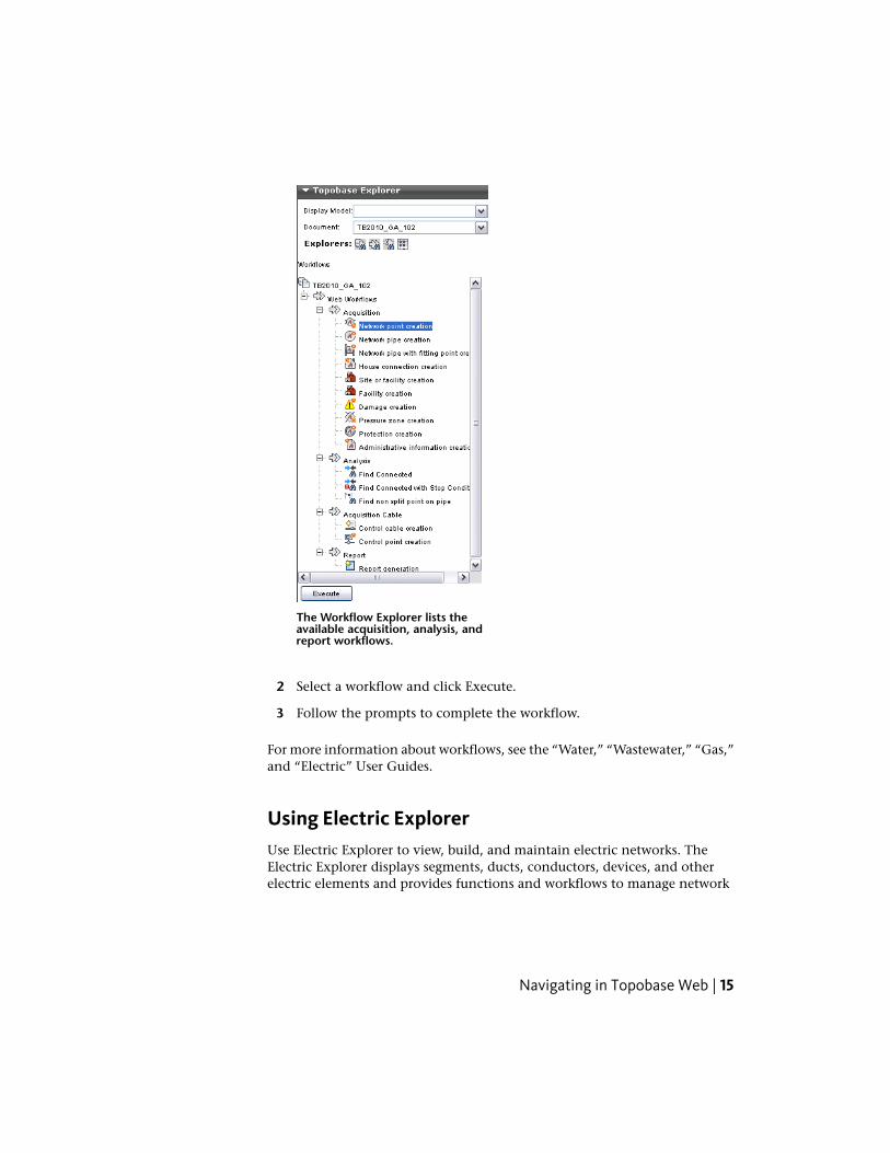
The Workflow Explorer lists theavailable acquisition, analysis, andreport workflows.
2 Select a workflow and click Execute.
3 Follow the prompts to complete the workflow.
For more information about workflows, see the “Water,” “Wastewater,” “Gas,”and “Electric” User Guides.
Using Electric ExplorerUse Electric Explorer to view, build, and maintain electric networks. TheElectric Explorer displays segments, ducts, conductors, devices, and otherelectric elements and provides functions and workflows to manage network
Navigating in Topobase Web | 15
features. Each class of features is displayed in a separate container so you canselect multiple features and edit them at once.
To select a value from a list
In the data grid, when you select a value from a list that contains a largenumber of entries, you can use a look up tool to quickly find the desired item.
1 Click the input field.
2 Enter the complete value or some characters.
NOTE Press the Down arrow to select a value from the list without enteringa search character.
3 Press Enter or click the check mark next to the input field to startsearching.
The background color of the input field indicates how many entries werefound.
■ White— No search has occurred. Click the green icon next to the inputfield to search for the value.
■ Green— One match found. Press Enter to select the item. To redisplay thelist, press the Down arrow on the keyboard.
■ Orange— Zero or multiple matches found. Use the left and right arrowkeys to display them. Press Home to go to the first item, and End key togo to the end of the list. To select a value, click it. To cancel a selection,press Esc.
Using Specialized Modules
Using Topobase WastewaterUse Autodesk Topobase Wastewater to document, maintain, and presentwastewater networks and infrastructure.
Use classification workflows to determine the quality of sections and manholesbased on inspection data. Damaged features are coded and quantified basedon a chosen wastewater standard.
16 | Chapter 1 Topobase Web User Guide

NOTE Before you can use classification workflows, you must import inspectiondata using Topobase Client.
To classify imported information
1 On the Topobase Task Pane, click Workflow Explorer.
2 Expand the Classification workflow and right-click Classify Import. ClickExecute.
3 In the Workflows group, select the import file to classify and click OK.
The classification results are shown in the feature explorer.
You can also classify specific features, inspections or observations (or performmanual classification) using function forms.
To classify using function forms
1 On the Topobase Task Pane, click Document Explorer.
2 Open a feature class form, for example, Manhole or Section.
3 Select one or more features.
4 Click Classification ➤ Classify.
For detailed information see the “Topobase Wastewater User Guide.”
Using Inspection Editor
Use the Inspection Editor to review imported information for a section of thewastewater network.
To use the Inspection Editor
1 Select a section and open its form.
2 In the Section form, click the Inspection Editor tab.
For detailed information see the “Topobase Wastewater User Guide”.”
Using Specialized Modules | 17

See also:
■ Setting Wastewater Document Options (page 47)
■ Using Workflow Explorer (page 14)
Using Topobase ElectricUse Autodesk Topobase Electric to manage and analyze electric distributionand transmission networks. You can manage both underground and overheadelectric infrastructure.
There are two versions of Topobase Electric: North America (NA) and CentralEurope (CE). For detailed information see the “Topobase Electric User Guide.”
To work with Topobase Electric, use the following explorers on the TopobaseTask Pane.
■ Click Document Explorer to create new electric features. See UsingDocument Explorer (page 12).
■ Click Workflow Explorer to run analysis or maintenance processeson electric data. See Using Workflow Explorer (page 14)
■ Click Electric Explorer to view, create, and edit electric networkfeatures, manage the circuit and phase, and view connected features. SeeUsing Electric Explorer (page 15).
■ Click Manage Connections to manage logical topologies. SeeManaging Logical Connections (page 70).
Using Topobase GasUse Autodesk Topobase Gas to document, maintain, and present gas networksand infrastructure.
18 | Chapter 1 Topobase Web User Guide
To work with Topobase Gas, use the following explorers on the Topobase TaskPane.
■ Click Document Explorer to explore gas features. See Using DocumentExplorer (page 12).
■ Click Workflow Explorer to run acquisition or analysis processeson gas data. See Using Workflow Explorer (page 14).
■ Click Manage Connections to manage logical topologies. SeeManaging Logical Connections (page 70).
■ Click Topology Checker to validate network topologies. See CheckingLogical Topologies (page 66).
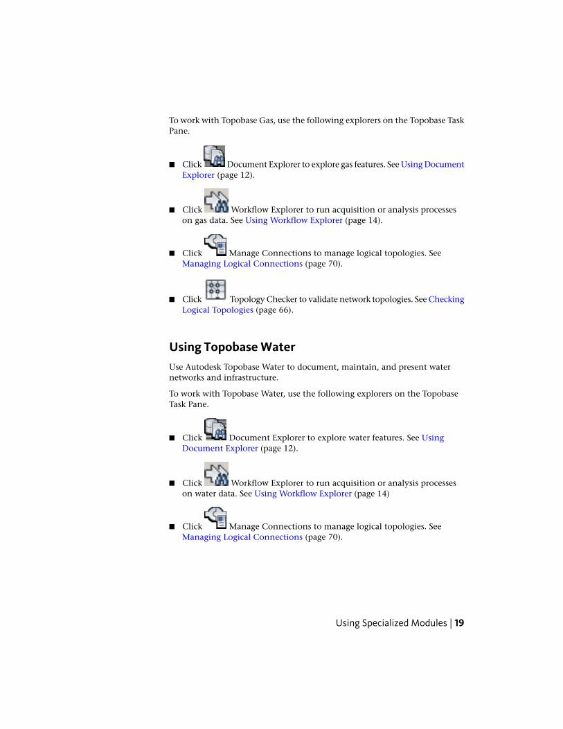
Using Topobase WaterUse Autodesk Topobase Water to document, maintain, and present waternetworks and infrastructure.
To work with Topobase Water, use the following explorers on the TopobaseTask Pane.
■ Click Document Explorer to explore water features. See UsingDocument Explorer (page 12).
■ Click Workflow Explorer to run acquisition or analysis processeson water data. See Using Workflow Explorer (page 14)
■ Click Manage Connections to manage logical topologies. SeeManaging Logical Connections (page 70).
Using Specialized Modules | 19
■ Click Topology Checker to validate network topologies. See CheckingLogical Topologies (page 66).
Tracing a water network
The steps below can be reproduced using the water demo data set, and theFusion layout.
1 Open the workspace.
2 On Topobase Explorer, click Position Finder.
3 Under Query, select Feature.
4 Under Feature Class, select Line.
5 Under Feature, select an FID, such as 52420.
6 Click Find.
7 On Topology Explorer, click Workflow Explorer.
8 Under Analysis, select Find Connected. Right-click, and click Execute.
9 On the Workflow pane, under Start/Stop Features, click Select StartFeature.
10 In the map, select a pipe.
11 Click Select Stop Feature.
12 In the map, select the pipe.
13 Click OK to start the tracing.
See also Analyzing Network Topologies (page 67).
For more information see the “Topobase Water User Guide.”
Finding Features in Your MapThere are three ways to find data in Topobase Web:
■ Select features in the map manually. (page 41)
■ Use Position Finder. (page 21)
20 | Chapter 1 Topobase Web User Guide

■ Use a feature form to filter and highlight data in the map. (page 38)
Using Position FinderUse Position Finder to locate a specific feature in the map. Locate any featurethat has geometry, for example, a building or a parcel.
For information about configuring Position Finder for Topobase Web, see the“Topobase Administrator Guide.”
To use Position Finder
1 On the Task Pane, click Position Finder.
2 On the resulting page, specify the parameters for the search.
■ If the workspace contains multiple documents, under Document,select the document containing the feature to locate.
■ Under Query, select the search to use.For example, locate a feature by Feature Class and Feature ID, or byAttribute. The available query options depend on how youradministrator configured Position Finder.
Each search has its own options. Use the options to narrow the search.
■ Click Find to locate the feature.
Finding Features in Your Map | 21
Using Markup Functions
RedliningUse the Redlining tool to add temporary markup to a map. When you print,redlines are printed. However, you cannot save redlines, and redline geometryis not stored in the database.
To add redline geometry
1 On the Task Pane, click Redlining.
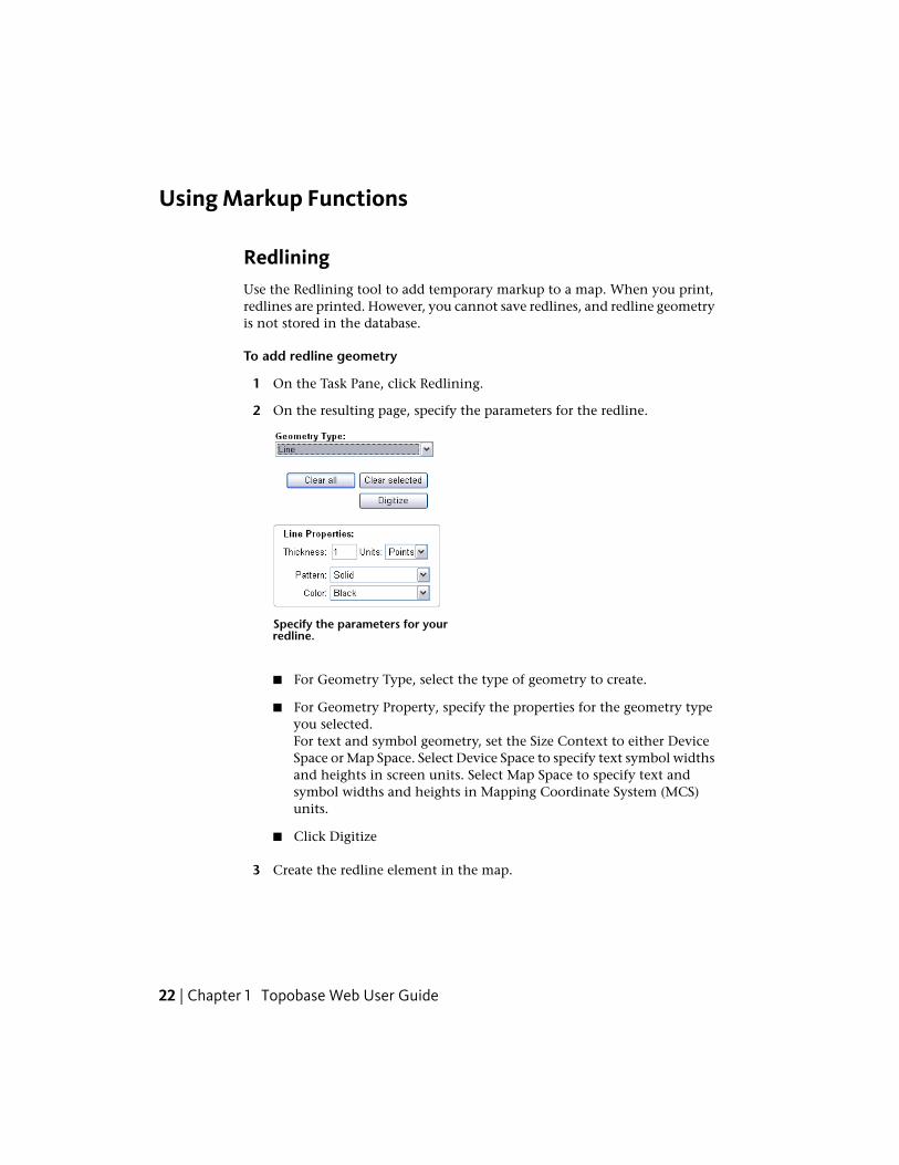
2 On the resulting page, specify the parameters for the redline.
Specify the parameters for yourredline.
■ For Geometry Type, select the type of geometry to create.
■ For Geometry Property, specify the properties for the geometry typeyou selected.For text and symbol geometry, set the Size Context to either DeviceSpace or Map Space. Select Device Space to specify text symbol widthsand heights in screen units. Select Map Space to specify text andsymbol widths and heights in Mapping Coordinate System (MCS)units.
■ Click Digitize
3 Create the redline element in the map.
22 | Chapter 1 Topobase Web User Guide

To remove redline geometry
■ To remove a single redline element, click the element to remove. ClickClear Selection.
■ To remove all redline elements in the map, click Clear All.
DimensioningYou can add temporary dimension lines or orthogonal markings to features.You cannot save these markings.
To add dimensions
1 Locate (page 21) and zoom to the features of interest.
2 On the Task Pane, click Dimensioning.
3 On the resulting page, specify the parameters for the dimension markings.
■ Click Dimension Line or Marking.
■ Under Drawing Layer, select the layer for the dimension elements.To create a new layer for dimension elements, click New and specifya layer name. To delete a layer, select the layer and click Delete.
Using Markup Functions | 23
■ Under Layer Properties, specify options for the placement andappearance of the dimension elements.
■ Click Save to make your settings the default for future dimensionelements.
■ Click Digitize and draw the dimension element in the map.
4 To remove dimension elements, click Clear Objects.
Reporting and Sharing
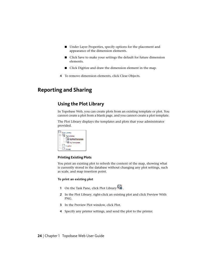
Using the Plot LibraryIn Topobase Web, you can create plots from an existing template or plot. Youcannot create a plot from a blank page, and you cannot create a plot template.
The Plot Library displays the templates and plots that your administratorprovided.
Printing Existing Plots
You print an existing plot to refresh the content of the map, showing whatis currently stored in the database without changing any plot settings, suchas scale, and map insertion point.
To print an existing plot
1 On the Task Pane, click Plot Library .
2 In the Plot Library, right-click an existing plot and click Preview WithPNG.
3 In the Preview Plot window, click Plot.
4 Specify any printer settings, and send the plot to the printer.
24 | Chapter 1 Topobase Web User Guide

Using Plot Templates
A plot template specifies settings for all the plots that use that template. Youcan set any unspecified settings in the plot template at plot time. For example,a template specifies the scale, paper size, and layout elements for the plot, buteach individual plot can specify the display model to use, the printer to useand the insertion point and rotation for the map placeholder.
Your administrator provides the display models to use.
To create a plot using a template
1 On the Task Pane, click Plot Library .
2 In the Plot Library, right-click a template. Click Create New WithTemplate.
3 In the Create New Plot window, enter the parameters for the plot.
■ For Name, specify the name of the plot.
■ For Save In Plot Library Location, specify where, in the Plot Library,the plot will appear.By default, plots you create from templates are saved in the templatefolder's parent folder.
■ For Choose Template From Library, specify the plot template to use.The template you right-clicked is selected. To change it, click Browse,select a template from the list, and click Save.
4 For Template Maps, specify the map area to display in the placeholderdesignated by the template.
If a map is not yet captured, under Actions, click Capture Map.
■ In the Capture Map Settings window, to change the area that isplotted, click Draw New and drag a frame around the area to map.The ratio of height and width does not change, and the scale isadjusted.
■ In the Capture Map Settings window, specify the scale for the map.
To choose a scale from a list of predefined scale settings, click .Click a scale setting and click Select.
■ Under Map View, select a display model. Click Generate to refreshthe map using the selected display model.
■ Optionally, change the rotation by entering an angle.
Reporting and Sharing | 25

■ To change the insertion point, click Select and click the insertionpoint in the map.The insertion point and the plot scale will determine the area includedin the map placeholder.
■ Click Save Capture.The Create New Plot dialog box now shows the map as Captured. Ifthere are more maps to capture (as defined by this template), repeatthe capture process.
5 For Preview, specify the preview format.
6 Click Create to create the preview and the plot.
The plot preview is displayed.
■ To send the plot to the printer, click Plot.
■ To see information about this plot or to change the scale, click EditPlot Attributes.
For more information about plots, see “Topobase Client User Guide.”
Printing ReportsThe administrator must define reports and associate them with a form. Thenyou can generate those reports in Topobase Web.
To print a feature class report
1 Open the feature class form (page 30) and filter (page 38) for the recordsto print.
2 On the form toolbar, click Print .
3 In the Report dialog box, select the report.
4 Specify which records to print.
■ Current Record Only prints only the current record.
■ All Records Of the Selection prints all currently selected records (allfiltered records).
26 | Chapter 1 Topobase Web User Guide

You can print any report that has been defined with Topobase Report Designerin the current document.
To print a document report
1 In Document Explorer, right-click the document node at the top of thetree. Click Report.
2 Select the report to print.
3 Click Preview.
4 Use your browser’s print command to print the report.
Creating Polygon/Line Definition ReportsUse Polygon/Line Definition to create detailed polygon or line definitionreports. For example, you can generate a parcel report that lists areas, distancesbetween the parcel border points, parcel borders, points, and parcel numbers.
Before you can use these reports, an administrator must use the Report Designerto define the feature classes that store the lines and points. This configurationis stored in the TB_SURFACE_* system tables. For more information on thesetopics, see the “Topobase Administrator Guide.”
To create a Polygon/Line Definition report
1 Click Polygon/Line Definition.
2 In the Report For Lines/Polygons dialog box, select the features for thereport.
3 Select the job for the report.
4 Select the report to generate.
5 Optionally, select the Reverse Direction Of The Points check box.
6 Click Calculate/Preview.
Exporting Feature DataYou can export data from feature class forms to various formats.
Reporting and Sharing | 27

To export data from feature class forms
1 Display the feature class form.
2 Filter the data to export.
NOTE Only the filtered records are exported.
3 On the form toolbar, click Tools ➤ Export. Click the format for theexported data.
Choose a Direct option to export all data as stored in the database (DBdata). If you choose Excel (Direct), Excel columns are sorted like thecolumns in the database.
Choose a Form Data option to export all data. Use this option if you donot want to export the ID of the related feature (stored in the database)but the value shown in the form. If you choose Excel (Form Data),columns are sorted like the columns in the form.
■ Excel: You can export all data shown in a form, including values thatare only shown by controls, like SQL Label, and values without explicitrelation.CR characters (Ascii 13) are replaced, because Excel only needsLineFeed. This is required for multiline text.
■ ASCII File: Exports data to text (*.txt) files.
■ XML: Exports to XML files. Point feature coordinates are written asGEOM.X and GEOM.Y columns.
■ SQL: Exports to SQL files. You can select:
■ Oracle SQL loader files (with spatial geometry)
■ Oracle SQL files (insert statements without spatial geometry)
■ PostGre SQL files (insert statements with PostGre spatial geometry)
4 Check the columns to export.
NOTE Only columns that are visible in the form are exported;group-suspended columns are suppressed.
■ Columns: Select or deselect the columns to export. Select Clear All toselect or deselect all fields. Change the order using the arrow buttons.
28 | Chapter 1 Topobase Web User Guide
All feature class attributes are listed, with control titles (captions) andfield names in parentheses
■ Control Titles: Select this option to include the control title in theexport. This is the caption, and not the name of the column in thedatabase. Column names are always exported by default.By default, this setting is not selected for direct export, but it is selectedfor form export.
Creating and Editing
Creating FeaturesUse the feature classes in Document Explorer to create new features with orwithout displaying the associated form. The form allows you to add attributedata.
To create a new feature without attribute data
1 In Document Explorer, right-click the feature class.
2 Click Digitize.
3 Draw the new feature.
4 To finish digitizing, hold down the Ctrl key and click.
You can add attribute data later using feature class forms (page 35).
To create a new feature with attribute data
1 In Document Explorer, right-click the feature class.
2 Click Digitize With Form.
3 Draw the new feature.
When finish creating the geometry, the feature class form is displayedso you can add attribute data.
For more information about creating features, see the “Topobase Client UserGuide”.
Creating and Editing | 29

Editing Feature InformationUse feature class forms to display and edit feature data.
Right-click any tab in the feature class form to use shortcut menus. Input fieldshave their own shortcut menus.
TIP You can also display the shortcut menus by clicking Tools in the formtoolbar.
To edit attribute data
1 In Document Explorer, right-click the feature class to edit.
2 Click Show Form.
3 On the form toolbar, click Edit Record.
4 Enter the attribute values. Click Update.
For more information about using feature class forms, see the “Topobase ClientUser's Guide.”
For more information about customizing forms, see the “TopobaseAdministrator's Guide.”
Using TemplatesA template is a set of features you can reuse. A template contains geometry,attributes, labels and internal connectivity. Use templates to create groups offeatures to reuse. For example, create a template for a transformer bank,compatible unit, substation, or cross section.
To define a template, select an existing feature in a map and convert it intoa template. After you create the template, you can delete the original feature.Templates are defined in a local coordinate system. When you instantiate atemplate in the map, you digitize the origin and specify an orientation.
To create a template
1 If necessary, create the features to group as template.
2 Select the features to group as template.
Shift-click to select multiple features. Press Enter to complete the selection.
30 | Chapter 1 Topobase Web User Guide

3 In Document Explorer, right-click the feature class for the template. ClickCreate Template From Selection.
4 Select the origin and specify the orientation.
The origin defines the insertion point at feature creation time. Theorientation specifies the basic orientation (null orientation) of the featureset. When you use the template, you are prompted for an insertion pointand an orientation.
5 In the window that displays, do the following:
■ Enter a template name.
■ Use the tabs to specify more properties.
■ General tab— Specify whether to group features when moving,rotating, or deleting them. Specify any reference records (page 37)for specific features.
■ Access tab— Assign the template to another appropriate featureclass.
■ Connectivity and Relations tabs— View connections and relationsof the template features.
For more information on these tabs, see the “Topobase Client UserGuide.”
■ Click Save.
To digitize features using a template
1 In Document Explorer, right-click the feature class to which the templatewas assigned. Click Digitize From Template.
2 In the template list, select the template to use for creating the new feature.
3 Click OK.
4 In the map, select the origin point. Then select a second point thatindicates the orientation.
To view a template definition
1 In Document Explorer, right-click the feature class to which the templatewas assigned. Click Manage Templates.
2 Do any of the following in the Manage Templates dialog box:
Creating and Editing | 31

Delete— Select the template and click . If you delete a non-groupedtemplate, you must confirm the deletion. The features that were created usingthe template are not deleted. If you delete a grouped template, the featuresthat were created using the template are ungrouped, but not deleted.
Connectivity and Relations tabs— View connections and relations of thetemplate features.
Access tab— Assign the template to another appropriate feature class.
For more information about using and managing templates, see the “TopobaseClient User Guide.”
Construction and CalculationUse the Construction toolbar to start the construction functions.
The construction tools appear on theTopobase Explorer pane.
You can calculate point and line features and store them into the database.
For more information, see Construction and Calculation (page 73).
Deleting FeaturesYou can delete features from the database. When you work with Topobasejobs you can delete features that have been processed within a job.
To delete a feature
1 Click the feature.
2 Click Delete Feature .
See also:
■ Deleting Job Modifications
32 | Chapter 1 Topobase Web User Guide

Splitting LinesFor the utility modules, such as Wastewater, Water, or Gas, use the Soft Splitor Hard Split commands to digitize a point and split a network line.
When you use Soft Split to divide a line into two, each resulting feature hasits own geometry, but they both use the same attribute data.
When you use Hard Split, the resulting features have their own geometry andtheir own attribute data. Use Hard Split for point features of major importance,such as a pump or a valve. Use Hard Split if the attributes of the pipe (forexample, diameter, material, or model) change after the split.
To digitize a point and split a line
1 In Document Explorer, right-click a feature class (for example, Pipe orSection).
2 Click one of the following.
Soft Split (Only Geometry)
Hard Split (Also Attributes)
3 In the map, select the line.
4 In the Select dialog box, select the point feature class to digitize. Digitizethe point.
For more information, see the Topobase “Wastewater,” “Water,” or “Gas” UserGuide.
Adding LabelsYou can create label text for any feature in the drawing that has an active andvalid label definition.
To add a label
1 Click Create Label.
2 In the map, click a feature to label.
Click a feature whose feature class has an associated label feature class.
3 If prompted, select a label definition.
4 If prompted, specify a position.
Creating and Editing | 33

The label is created according to its definition.
NOTE Auto labels are created instantly without any user action.
For more information about defining and using labels, see the “TopobaseAdministrator Guide.”
Performing IntersectionsUse the Topobase intersection routines to calculate intersections between twofeature classes. Intersections can be defined in the Topobase data modeladministrator.
Intersections are also called overlays. For example, to determine which borderpoints lie within which parcels you would see where those feature classesintersect. In that example, you would examine the intersection between apolygon feature class and a point feature class.
To start an intersection
1 In Document Explorer, expand the Intersections node.
2 Right-click the intersection and click Intersect.
3 In the Select The Perimeter For The Intersection dialog box, select one ofthe following:
■ Intersect Over Area. Select features and click Select.
■ Intersect Over All. All features are selected. Click OK.
For more information about defining intersections, see the “TopobaseAdministrator Guide.”
Using Data CheckerUse the Topobase Data Checker to validate the quality of your data. Youradministrator must define the checks.
The result of the checks, for example features with wrong or inconsistent data,is displayed in the Feature Explorer.
34 | Chapter 1 Topobase Web User Guide
To start Data Checker
1 In Document Explorer, right-click the document node at the top of thetree. Click Data Checker.
2 In the Data Checker window, select the checks to run.
3 Click Execute.
For more information about configuring data checks, see the “TopobaseAdministrator Guide.”
Using Feature Class Forms
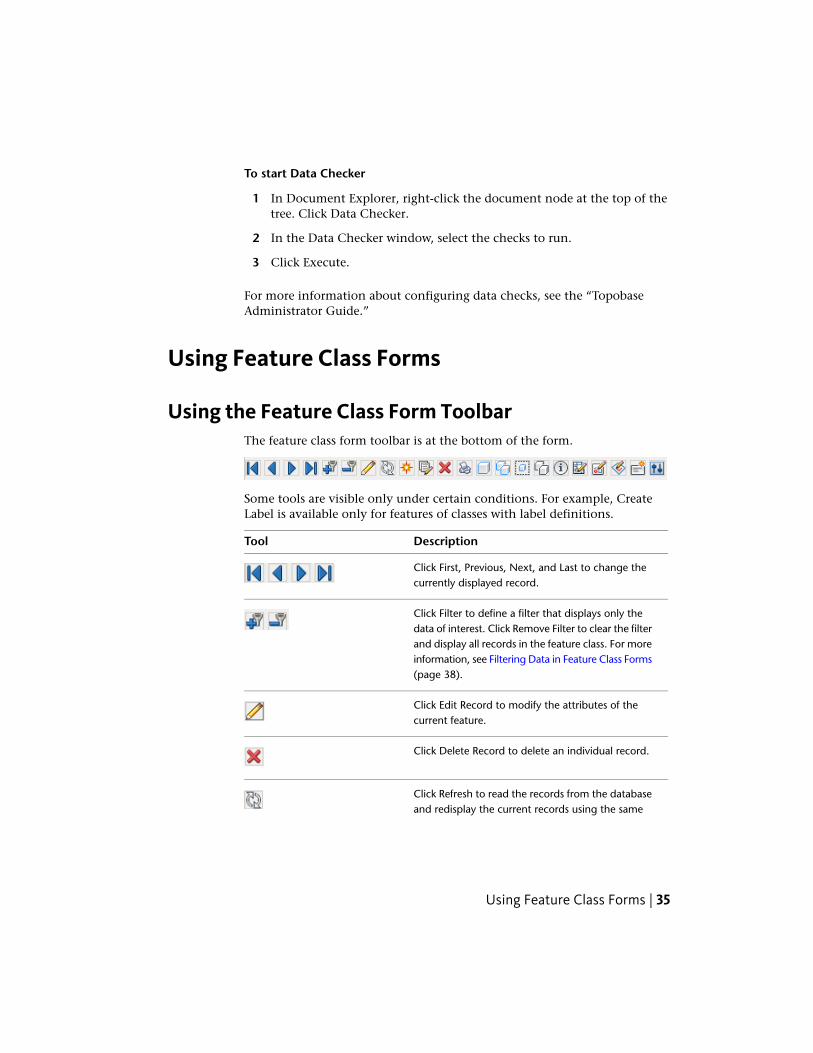
Using the Feature Class Form ToolbarThe feature class form toolbar is at the bottom of the form.
Some tools are visible only under certain conditions. For example, CreateLabel is available only for features of classes with label definitions.
DescriptionTool
Click First, Previous, Next, and Last to change thecurrently displayed record.
Click Filter to define a filter that displays only thedata of interest. Click Remove Filter to clear the filterand display all records in the feature class. For moreinformation, see Filtering Data in Feature Class Forms(page 38).
Click Edit Record to modify the attributes of thecurrent feature.
Click Delete Record to delete an individual record.
Click Refresh to read the records from the databaseand redisplay the current records using the same
Using Feature Class Forms | 35

DescriptionTool
filter. Use this function in applications that use trig-gers in fields.
Click New Record to create a new record withoutgeometry. To digitize geometry at any time clickDigitize New Geometry For Selected Feature. Tocreate a completely new feature and add attributedata at the same time, click Digitize New Feature.After you create the geometry, a new blank recordis displayed so you can add attribute data. Click Di-gitize Inner Ring to create polygon features with ahole, for example, an island in a body of water orthe footprint of a building with a courtyard. Theinner and outer ring are parts of a single feature.Based on the outer ring you can either digitize theinner ring or select an existing polygon or featureto be inserted. Only polygon feature classes have atool for creating inner rings.
Click Global Update to modify all records in thecurrent filter using the same values. For more inform-ation, see Updating Records Globally.
Click the Highlight icons to highlight the geometryfor a selected record or for a set of records. You canalso highlight the geometry of features related to arecord or set of records. Use Unhighlight to clearthe highlighting.
Click Print to generate standard reports or user-defined reports for each form. For more information,see Printing Reports (page 26).
Updating Records GloballyYou can modify all records in the current filter using the same values.
To globally update records
1 In the feature class form, select all records to change.
36 | Chapter 1 Topobase Web User Guide
2 On the form toolbar, click Global Update.
3 Enter your changes.
4 Click Global Update again to save your changes to the database forthe selected records.
Adding Data Using Reference RecordsA reference record is a template for new records.
Reference records consist of a set of defined attributes and their values(reference attributes). When you insert a new record using a reference record,the reference attributes are entered for that record. Use reference records toimprove performance and accuracy when you enter attributes repeatedly. Youcan save and manage several reference records.
You can use reference records in a feature class form in Edit mode. You canalso use reference records when you digitize features or create features usingworkflows.
To define reference records
1 Display the feature class form.
2 On the form toolbar, click Tools ➤ Reference Records ➤ Add.
3 In the New Reference Record dialog box, enter a name for the referencerecord.
4 Select Public if the reference record is available to all users.
Public reference records are available to all users who are logged in.Non-public reference records are only available to the current user.
5 Select Use Last Value As Reference to use previous values.
If you select Use Last Value As Reference, reference data is dynamic andwill be set to the values the user entered before in the reference attributes.When you create a new record, the values are shown in the input fields.If necessary you can change the values before update.
If you do not select Use Last Value As Reference, the next new record willhave the defined reference values.
6 Click OK.
Adding Data Using Reference Records | 37

The input fields are highlighted, so you can define the attributes of thereference record.
7 Enter the reference values.
8 Click Save to activate and save the reference record.
To use a reference record
1 Display the form for a feature.
2 Click Edit Record.
The reference record appears in the status bar on the right. *No Referenceindicates that no reference record will be applied.
3 Click to select a predefined reference record.
Filtering Data in Feature Class Forms
Filtering TechniquesYou can filter features from within feature class forms or from the map.
In feature class forms, use these techniques to filter data:
■ Use the filter commands on the input field shortcut menus.
■ In Edit mode, use on the toolbar to define or remove a filter.
■ In Filter mode, enter the values to filter in the input fields.Select any of the following options from the list box at the right bottomstatus bar of the form.
■ Simple Filter: The default.
■ Additive Filter: Connects the previous and the new filter with an SQLAND condition.
■ Or Filter: Connects the previous and the new filter with an SQL ORcondition.
38 | Chapter 1 Topobase Web User Guide

■ Define a SQL statement to select the records.
To filter with SQL statements
1 In the feature class form, in Edit mode, click ➤ Filter ➤ SQLFilter.
2 In the SQL Filter dialog box define the SQL filter statement.The SQL Filter dialog box shows the select statement that was usedfor the active filter, such as “rownum<101” for a start filter or “(AREA> 300) AND (ID_QUALITY = 2)”.
NOTE OrderBy clauses that were defined in the form designer optionsare displayed and can be set. You must separate the Order and the Byexpression by exactly one blank space.
3 Click OK to execute the filter.
NOTE The filter is not saved. To save and reuse filter definitions, see the Savingand Reusing Filters (page 40) topic.
■ Use (Feature Information) in the feature class form to select the featuresin the drawing of that feature class. Selected features that are not in thefeature class are ignored.
■ Use Excel to filter data.See Excel Export.
■ Use database projections. See Filtering Related Records (page 42).
You can also select elements in the drawing manually. See Spatial Selection(page 41).
Filter Expressions
DescriptionExpression
NOTE Oracle is case sensitive whensearching text.
Less than or equal to<, <=
Filtering Data in Feature Class Forms | 39

DescriptionExpression
Greater than or equal to>; >=
Unequal<>
A wildcard character. In Oracle, use thewildcard character % in tables.
*
For blank field searching - database NULLIS NULL
For non-blank field searchingIS NOT NULL
Searches by Date. All data created between17.03. and 19.03 is found.
>17.3.99 <19.3.99
Filtering by multiple values (numeric fieldsonly)
Available operators for linking:ExamplesAND, OR; unspecified = AND; = OR| = || = OR& = && = AND
Single range specification>50 <20
Greater than 5 and less than 10>5 AND <10
5 or 10 or 155;10;15
5 OR 10 OR 15
Less than 5 or 15<5 OR 15
NOTE You can also filter columns of the type Date by typing only the numberindicating the year.
Saving and Reusing FiltersYou can save and reuse filter definitions.
40 | Chapter 1 Topobase Web User Guide
To re-use filter conditions, execute any filter, then start the Filter Managerand add a filter. The previously executed filter (SQL statement) appears as thedefault. You can add or modify it.
You can use input parameters in SQL filter select statements. For example, thefilter can prompt the user to enter a length. If the parameter is a numericvalue, use the # character. If it is a text value, use the $ character.
Example: {#length} {$Name}
select * from WW_SECTION where
pipe_length > {#Length}
To start the Filter Manager
1 Show the feature class form.
2 On the form toolbar, click ➤ Filter ➤ Filter Manager.
3 Do any of the following:
■ To add a filter definition, click Add. The most recently used filterexpression appears as the default.
■ To modify a filter definition, click Modify and make your changes.
■ To remove a filter definition, click Remove.
■ To execute a stored filter, right-click and click Filter ➤ Execute.
Spatial SelectionYou can select features manually, and then view the results of your selectionin the feature class form.
To perform a spatial selection
1 In the Document Explorer, right-click a feature class and click SpatialSelection.
2 Under Selection Type, select a rectangle, polygon, or point and click thedynamic prompt in the dialog box.
3 Click (Feature Information) on the toolbar to view the results of yourselection in the feature class form.
Filtering Data in Feature Class Forms | 41

Filtering Related RecordsUse projections to show related records.
For example, you can select all the labels that belong to the features youselected. The Reference button displays only the labels of the current feature.Projection displays all labels of all features you filtered.
To filter data with projections
1 In the feature class form, click ➤ Projection.
2 Click the All Projections tab to see a list of all existing feature classrelations.
3 Select a relation and click OK.
To add a named projection
You use Topobase Client to add named projections.
Setting Topobase Web Options
Setting Application OptionsYou can specify job, map, COGO, and plug-in options.
To set application options
1 Click Setup ➤ Options.
2 Do any of the following:
■ Click Job to specify job lease duration and regenerate options. SeeSetting Job Options (page 43).
■ Click Map Options to specify feature zoom options for highlighting.See Setting Map Options (page 43).
■ Click COGO to set options for the construction and calculationfunctions. See Setting COGO Options (page 44).
■ Click Plug-Ins to view loaded plug-in applications.
42 | Chapter 1 Topobase Web User Guide

Setting Job OptionsJob Options specify the behavior of Topobase Web when you select a job towork with.
To set Job options
1 In Document Explorer, right-click the document node at the top of thetree. Click Document Options.
2 In the tree view, click Jobs With Topologies.
3 Set the following options:
■ Duration Of Job Leasing: Specifies the period for automatic job leasing.The leasing period starts as soon as the job is selected.
■ Automatically Lease The Selected Job: Leases a job automatically. Ifyou select this option, you can enter a leasing period.
NOTE You can lease jobs manually using the Job Manager.
See also:
■ Working with Jobs
Setting Map OptionsMap Options specify settings for digitizing and for highlighting.
To set Map options
1 In Document Explorer, right-click the document node at the top of thetree. Click Document Options.
2 In the tree view, click Jobs With Topologies.
3 Set the following options:
■ Snap Radius For Digitizing In TB Web: Enables and specifies the snapradius. When you digitize points, existing points within the snapradius are found. For example, this setting is used when you digitizea point to close a polygon.
■ Vicinity For Digitizing Points: Searches for points that already existin the database when creating a new point feature. This option finds
Setting Application Options | 43

points that are in the vicinity of the new point and that have definedvalues for "Z (height)" and "QUALITY". See the “TopobaseAdministrator Guide” for more information.
■ Zoom For Feature Highlight/Zoom GoTo: Specifies the zoom factorfor highlighting the current feature of a feature class form or inDocument Explorer using the highlight button.
■ Configuration For Point Feature Classes: Specifies the map view. Entervalues.
■ Configuration For Other Feature Class Types: Specifies the map view.Enter a magnification factor. The view size is calculated based on theextents of the selected features.
Setting COGO OptionsCOGO options define settings for Topobase construction functions.
To set COGO options
1 In Document Explorer, right-click the document node at the top of thetree. Click Document Options.
2 In the tree view, click Jobs With Topologies.
3 Set the following options:
■ Right Angle Course: Specifies the mode for right angle coursecalculation. Select either of the following:
■ Point Mode—The right angle course is defined by an arbitrarysequence of known points and measured sections.
■ Base Line Mode—The right angle course is defined by two existingpoints that specify the base line section followed by measuredsections.
■ Precision: Specifies calculation precision. The default is 0.001.
■ Split Tolerance: Specifies whether a line can be considered straightafter inserting or extracting a point.This value specifies the maximum distance of a point from the line,which must be greater than the spatial tolerance.
44 | Chapter 1 Topobase Web User Guide

■ Split Line After Inserting Point: Splits the line after you use the InsertPoint command.
■ Point Insertion Settings: Specifies how the Precision and Reliabilityattributes are set by the Survey application when you use the InsertPoint command to insert a point into a line. When an existing pointis projected onto a line, its reliability is improved and its coordinatesare changed.
■ Precision: Defines the feature attribute where the precision of aninserted point is saved.
■ Reliability: Defines the feature attribute where the reliability of theinserted point is saved.This attribute usually refers to a domain *_TBD. You can specify thevalue (*_TBD.ID) for the two states: Reliable and Not Reliable.
For example, reliability values could be stored in the domain tableRELIABILITY_TBD where
ID = 1 is not reliable
ID = 2 is reliable
■ Reliable: Specifies the reliable value ID. For example 2.
■ Is Not Reliable: Specifies the not reliable value ID. For example 1.
Setting Document OptionsDocument options apply to the currently selected document in DocumentExplorer.
To set document options
1 In Document Explorer, right-click the document node at the top of thetree. Click Document Options.
2 Do any of the following:
■ Click Common to view general document information, such as thename of the database schema.
■ Click COGO And Dimensioning to set COGO document options. SeeSetting COGO and Dimensioning Document Options (page 46)
Setting Document Options | 45

■ If you use the Wastewater (page 47) or Electric (page 47) versions ofTopobase, you can set document options related to those versions.
Setting COGO and Dimensioning Document OptionsCOGO And Dimensioning document options control construction issues thatare specific to only one document.
See also Construction and Dimensioning.
To set COGO and Dimensioning options
1 In Document Explorer, right-click the document node at the top of thetree. Click Document Options.
2 In the tree view, click Jobs With Topologies.
3 Set the following options.
■ Delete Construction Features From The Document: Deletes thetemporary COGO features to clarify the construction workflow.Normally these are deleted as soon as Topobase COGO is finished.
■ Dimension Feature Class For: Specifies the dimension feature classesto store dimensioning that can optionally be created when you usethe COGO commands.
■ Orthogonal Calculation: Selects a dimension feature class that storesthe orthogonal dimensioning.
■ Arc Intersection: Selects a dimension feature class that stores the arcdimensioning.
■ Dimensioning: Settings for dimensioning.
■ Constant Offset For Aligned Dimensioning: Specifies an offset valuefor aligned dimensioning.
NOTE Set general COGO options using COGO application options (page 44).Click Setup ➤ Options.
46 | Chapter 1 Topobase Web User Guide

Setting Wastewater Document OptionsWastewater options are available only in wastewater documents.
To set Wastewater document options
1 In Document Explorer, right-click the document node at the top of thetree. Click Document Options.
2 In the tree view, click Wastewater.
For more information, see the “Topobase Wastewater User Guide.”
Setting Electric Explorer Document OptionsElectric options are only available in electric documents.
To set Electric Explorer document options
1 In Document Explorer, right-click the document node at the top of thetree. Click Document Options.
2 In the tree view, click Electric Explorer.
3 In Electric CE documents, click Electric CE to specify Multi Conductorand Station Internal options.
For more information, see the “Topobase Electric User Guide.”
Setting Document Options | 47

48

Using Jobs in TopobaseWeb
Navigating Topobase JobsTopobase Web provides the following:
■ Topobase Job Control (page 49) to work with jobs.
■ Topobase Job Explorer (page 50) to process the features that are modifiedin the selected job.
■ Topobase Job Manager (page 51) to process jobs and job states.
Using the Job ControlThe Job Control is visible only if the current document is job-enabled.
Use the Job Control to select a job to work with. If no jobs (other than thedefault Live job) are selectable, you must create a job (page 53). Use Job Manager(page 51) to create a job.
See also:
■ Selecting a Job (page 54)
2
49

Using Job ExplorerUse Job Explorer to view and process all modifications for a job. Job Explorergroups features as follows:
■ Inserted
■ Updated
■ Deleted
■ Locked Features (features you locked manually to modify in the future,but have not yet selected)
To start Job Explorer
■ In Topobase Explorer, select a job and click .
DescriptionJob Tools
Redisplays Job Explorer.
50 | Chapter 2 Using Jobs in Topobase Web

Opens the form for the selected feature.
Highlights or unhighlights the selected feature in the map.
Zooms to the selected feature.
Returns selected features to their original state, undoing anymodifications you made.
Displays the modifications of the selected feature.
Extracts the selected features, adds them to a new job, andsets them to live (partial posting). Available for pessimisticlocking.
Locks a feature manually. Available for pessimistic locking.
Unlocks a feature you locked manually.
Undoes all modifications to the selected job.
Checks for job conflicts and opens the Job Conflict Explorer.Available for optimistic locking. See also Managing Job Conflicts(page 58).
Changes the job state. See Changing the Job State (Job Trans-ition) (page 57).
Using Job ManagerJob Manager shows the jobs for the current document, grouped inchronological order or by job state.
Right-click job items to see their available operations.
Using Job Manager | 51
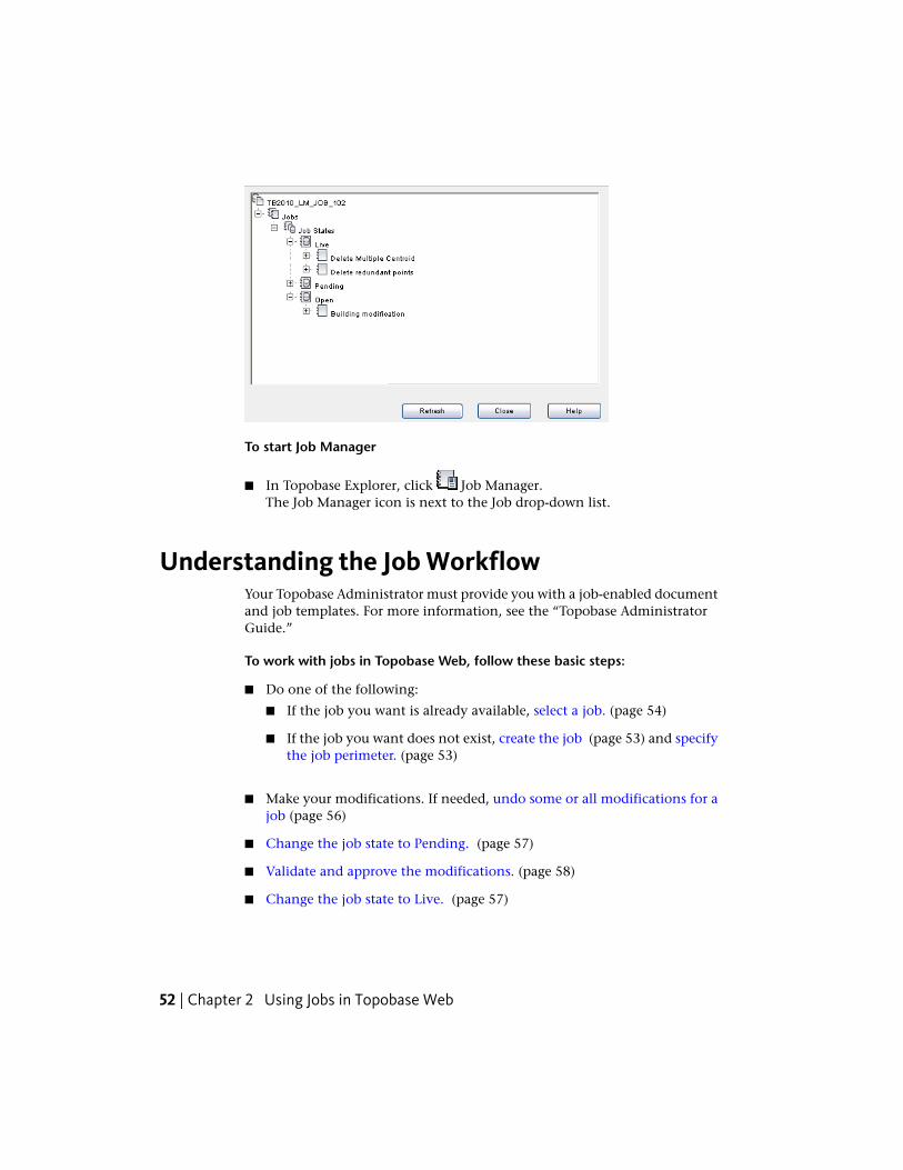
To start Job Manager
■ In Topobase Explorer, click Job Manager.The Job Manager icon is next to the Job drop-down list.
Understanding the Job WorkflowYour Topobase Administrator must provide you with a job-enabled documentand job templates. For more information, see the “Topobase AdministratorGuide.”
To work with jobs in Topobase Web, follow these basic steps:
■ Do one of the following:
■ If the job you want is already available, select a job. (page 54)
■ If the job you want does not exist, create the job (page 53) and specifythe job perimeter. (page 53)
■ Make your modifications. If needed, undo some or all modifications for ajob (page 56)
■ Change the job state to Pending. (page 57)
■ Validate and approve the modifications. (page 58)
■ Change the job state to Live. (page 57)
52 | Chapter 2 Using Jobs in Topobase Web

Creating a JobUse Job Manager to create a job.
To create a job
1 In Topobase Explorer, click to start Job Manager.
2 Right-click Jobs and click Create Job.
3 In the Create Job dialog box, select a job template and specify theproperties for the job.
4 Click OK.
5 When prompted to select the job perimeter, click Yes if you work withperimeters.
You can skip this step now and create job perimeters later.
6 In Job Manager, expand Jobs ➤ Job States ➤ Open.
The new job is listed.
7 Expand the new job to see which topics and feature classes it contains.
See also:
■ Using Job Manager (page 51)
■ Defining the Job Perimeter (page 53)
Defining the Job PerimeterAs soon as you create a job, you are prompted to define its perimeter. If youdon’t define the job perimeter at that point, you can define it later.
To define a job perimeter after the job is created
1 In Topobase Explorer, click to start Job Manager.
2 In Job Manager, expand Jobs ➤ Job States ➤ Open.
3 Right-click the job and click Select Perimeter.
Creating a Job | 53

4 In the Select Perimeter dialog box, select existing polygons or digitize anew perimeter. You can highlight the selected perimeter.
■ Create Perimeter From Topology: Click Select to select the polygonsto work with, for example, parcels to modify in the current job. Youcan select polygons that are disjointed. The system builds the jobperimeter from all selected polygons.If the job contains any topologies, the list box displays the topologypolygon feature class (*_TSUR).
If there are no topology feature classes in the job, the list box is empty.You can digitize the job perimeter.
■ Create Perimeter From Polygon: Select a polygon feature class fromthe list and digitize the perimeter. The list box shows all polygonfeature classes that are specified as perimeter and are job-enabled.
The job perimeter you selected or digitized is stored in its respective perimeterfeature class. If perimeters intersect, a warning is displayed. Perimeterintersections are allowed. Possible conflicts will be detected by the TopobaseJob Conflict Manager.
See also:
■ Creating a Job (page 53)
■ Managing Job Conflicts (page 58)
Selecting a JobIn the Job Control , select a job from the list of all available jobs. You can usea filter to reduce the number of jobs that are displayed in the list.
To filter the jobs by job state
1 From the Job Control, select Display Settings.
54 | Chapter 2 Using Jobs in Topobase Web

Display and filter settings are on theJob Control.
2 In the Display Settings window, select the types of jobs to list. Forexample, select Open to see all open jobs.
To select a jobs using a filter
1 From the Job Control, select Filter In Forms.
2 In the TB_JOB feature class form, use the filter tools to search for the job.See Filtering Data in Feature Class Forms (page 38).
3 Click Select Job to select the job.
4 Close the form.
NOTE In a job enabled document, if you select the Live job you cannot modifyany features.
You can now work with all topics and feature classes that are part of theselected job. If you have finished, you can change the job state, as for exampleto pending or you can delete your modifications.
See also:
■ Using the Job Control (page 49)
■ Deleting Job Modifications
■ Changing the Job State (Job Transition) (page 57)
Selecting a Job | 55

Undoing Modifications in JobsOnce you select a job, you can make modifications to features as you normallydo. You can undo some or all of your modifications.
You can undo some or all modifications you made in a job, as long as the jobstate is “open.”
To undo all modifications to a job
1 In Topobase Explorer, click to display Job Explorer.
2 Click Undo All Modifications In This Job.
To undo modifications to selected features
1 Select the features whose modifications you want to reverse.
2 In Topobase Explorer, click to display Job Explorer.
3 Click Undo Modifications Of Selected Features.
To undo some modifications
1 In Topobase Explorer, click to start Job Manager.
2 In Job Manager, expand Jobs ➤ Job States ➤ Open.
3 Right-click the job and click Delete Some Modifications.
The Delete Modifications dialog box displays all modifications down to thefeature level. They are grouped by event, for example, “inserted,” and bytopics. Use the toolbar to process the features. For example, select an item andhighlight it in the map. Then delete it.
See also:
■ Using Job Manager (page 51)
56 | Chapter 2 Using Jobs in Topobase Web

Changing the Job State (Job Transition)You can change the job state at the job level or at the job topic level (withina job, you can change the state topic-wise).
Changing the job state may require a password. Check with your Topobaseadministrator if you need a password.
If you change the job state for concurrent jobs, the system checks whether asingle feature was modified or deleted in different jobs. It tells you how tocontinue in case of conflicts.
NOTE You can define intersections that are calculated when the job state changes.
To change the job state in Job Manager
1 In Topobase Explorer, click to start Job Manager.
2 In Job Manager, expand Jobs ➤ Job States.
3 Right-click the job (or job topic) and click Change State or Change StatePer Topic.
4 In the window that displays, choose a new state for the job or job topic.
The current state of the job determines which new state you can choose.
Possible Job StatesCurrent Job State
PendingOpen
Open or LivePending
NoneLive
See also:
■ Managing Job Conflicts (page 58)
Changing the Job State (Job Transition) | 57

Managing Job ConflictsIf you work with several jobs, you can cause conflicts. For example, if youmodify a feature in one job, and then modify it differently in another job,the modifications may conflict.
You can lock features to avoid conflicts. Topobase supports two types of featurelocking: pessimistic feature locking, and optimistic feature locking. For moreinformation, see the “Topobase Administrator Guide.”
Pessimistic Feature Locking
With pessimistic feature locking, you cannot modify a feature in Job A if thefeature is being used in Job B. To resolve the conflict, perform a partial postingin Job B. The feature then becomes available in Job A.
When you modify a feature in a job, the feature will be locked automatically.To prevent job conflicts in advance, you can lock a feature manually, beforethey are modified. This ensures that no other job will use the features.
You cannot unlock a feature that is being modified in another job. A featurethat is locked by a job will be unlocked, either when you undo the modificationor when you set the job to live.
To lock and unlock features
1 In Topobase Explorer, select a job and click .
2 Expand the Locked Features node.
3 Select a feature class.
4 Click Lock Features.
5 Select the features in the map.
Features that are modified in the job are locked automatically.
6 To unlock the features, click Unlock Features.
The selected features are added to the Locked Features item, where onlymanually locked features are listed. Automatically locked features are listedunder the Inserted, Updated, and Deleted nodes.
58 | Chapter 2 Using Jobs in Topobase Web
Optimistic Feature Locking
With optimistic feature locking, job conflicts can be detected only when youchange the job state of all jobs.
■ Before you change the job state, you can check the job manually forconflicts.
■ When you change the job state, the system automatically checks whetherthe job contains features that have also been modified in other jobs.
To manually check for job conflicts, use Job Manager or Job Explorer. Jobconflicts are detected only if a concurrent job has a different job state. Forexample, no conflicts are detected as long as the jobs are open.
To use Job Manager to manually check for job conflicts
1 In Topobase Explorer, click to start Job Manager.
2 In Job Manager, expand Jobs ➤ Job States.
3 Right-click the open job and click Check Job Conflict.
4 Select the job state for the check and click OK.
To use Job Explorer to manually check for job conflicts
1 In Topobase Explorer, select a job and click .
2 Select the features to check.
3 Click Check For Job Conflicts.
4 Select the job state for the check and click OK
The Job Conflict Explorer displays any conflicts that are detected.Eachconflict is shown in a separate tab.
5 Expand the items in the Job Conflict Explorer. Do any of the following:
■ To cancel a modification, select the feature and click DeleteModification.
■ To see all features of the current job, expand the MyJob node
■ To see all jobs that are affected by the feature conflict, expand the<other jobs> node.
Managing Job Conflicts | 59

For example, if you modify a feature in one job and then delete thatfeature in another job, you cannot set them both to pending: a conflictwill result. Use Delete Modification to undo one of your changes andeliminate the conflict.
To use automatic job conflict validation
If you modify a feature in more than one job, the Concurrent Job dialog boxis displayed as soon as you change the job state of the first job.
■ Click Yes to change the job state.
■ To change the second job state, resolve the conflict in the dialog box thatdisplays.
See also:
■ Using Job Manager (page 51)
■ Using Job Explorer (page 50)
Creating a Historical Job ViewYou can show data as it was at a certain date, for example a year ago.
To create a historical job view
1 In Topobase Explorer, click to start Job Manager.
2 In Job Manager, expand Jobs ➤ Job States.
3 Right-click any job and click Historical View.
Leasing a JobBy default, data in a job is accessible only until that job is set to the Live state.You can make job data available, for example, to SQL Plus, using job leasing.
To make job data available to other applications before it is Live
1 In Topobase Explorer, click to start Job Manager.
60 | Chapter 2 Using Jobs in Topobase Web

2 In Job Manager, expand Jobs ➤ Job States.
3 Right-click the job and click Lease Job.
4 In the Lease Job window, specify the end date of the lease.
See also:
■ Setting Job Options (page 43)
Leasing a Job | 61

62

Working with Topologies
Area Topologies and Logical TopologiesTopologies model objects and phenomena of the real world. Use area topologiesto model land and other flat surfaces. Use logical topology wherever real worldobjects are connected to each other in networks.
Topobase utility applications, such as Water, Gas, Wastewater, or Electric CEuse logical topologies that comply with the Topobase utility model.
Area topologies
Use area topologies to represent parcels in cadastral applications. Parcels aredefined by their borders and incorporate data for the entire parcel. The borderin this model corresponds to a set of lines; the area corresponds to a polygon.With an area topology, you build areas (polygons) from a set of lines.
NOTE To digitize lines that build a closed polygon, specify a snap radius in theapplication Map Options. See Setting Map Options (page 43).
Logical topologies
Use logical topologies to connect features of any feature classes. The featuresdo not have to be spatially connected or have geometry. You can use a logicaltopology to connect points with points, lines with lines, lines to points, orattribute features with attribute features.
Topobase utility models are based on logical topologies that connect points andlines. For example, a logical topology can represent a wastewater network orelectrical transmission lines.
A network topology is a type of logical topology that is based on an arc-nodemodel and uses geometry.
3
63
For more information about topologies, see the “Topobase AdministratorGuide.”
Checking Area TopologiesYou can validate an area topology by checking the data in the topology supporttables for topology errors. Topology errors can include polygons crossingthemselves or centroids without polygons.
To check an area topology
1 In Topobase Explorer, click Document Explorer.
2 In Document Explorer, expand the Topologies item.
3 Right-click an area topology and click Topology Checker.
In the resulting window, each topology error type is stored in its ownnode.
4 Expand the nodes and items to see more details.
At the feature level, by default, the FID and name of the feature class isshown. Double-click an item to display the feature information relatedto the error message.
NOTE You must enable the double-clicking in the application options. SeeSetting Application Options (page 42).
The following error types may be displayed:
■ Centroid Has No Surface: A centroid feature does not lie within asurface. This may be due to a “Line Not In Closed Loop” error.
■ Line Not In Closed Loop: The edges of an area topology have to builda closed polygon. If a line is not part of a valid polygon, it is listedhere. This may be due to a “Lines Cross or Touch” error or a “LineCrosses or Touches Self” error.
■ Lines Cross Or Touch: An edge crosses or touches another line.
■ Line Crosses Or Touches Self: Lines cross or touch each other.
■ Centroid Has Null-Geometry: The centroid has no geometry (nocoordinates).
■ Line Has Null-Geometry: The edge has no geometry (no coordinates).
64 | Chapter 3 Working with Topologies
■ Surface Has Errors: Invalid polygons are saved in the system table_TSER. The reason for this error can be one of the following:
■ Line Has More Than {0} Vertices: The edge has many vertices.
■ Line Has Duplicated Sections: The edge has a section that has beendigitized twice (mostly forth – back – forth).
■ Line Has Adjacent Points: The edge has two or more adjacentpoints that lie together closer than the tolerance value.
■ Two Or More Rings Touch: An outer and inner ring or two innerrings touch.
■ Coordinates are outside of the spatial extents. : The coordinatesare outside of the spatial extents.
■ Surface Has Multiple Centroids: The surface has more than onecentroid. Expand the surface items to see the centroids.
5 Do any of the following:
■ Select an error and click .All features under the selected item are highlighted. To remove the
highlighting, click .
■ Zoom to the highlighted feature in your map. You can alsoclick Zoom On Click to automatically zoom to a feature when youclick it.
■ Open the feature class form to see feature information.
■ Delete the selected feature from the database.
■ Create missing centroids for the selected polygon. This tool isnot available unless a polygon is missing a centroid.
■ Find intersecting lines that were not detected by the standardtopology check. This tool is for rare cases, where intersecting lines donot cause invalid polygons. It can take a long time to execute.
Checking Area Topologies | 65

The polygons on the left can be detected only with Find IntersectingLines. The polygons on the right are detected using the standardtopology checker.
6 When you are finished repairing topology errors, click to make sureno errors remain.
Checking Logical TopologiesUse the Network Topology Checker to process logical topologies.
To check a logical topology
1 In Topobase Explorer, click Document Explorer.
2 In Document Explorer, expand the Topologies item.
3 Right-click a logical topology and click Topology Checker.
In the resulting window, each topology error type is stored in its ownnode.
4 Expand the nodes and items to see more details.
At the feature level, by default, the FID and name of the feature class isshown. Double-click an item to display the feature information relatedto the error message.
NOTE You must enable the double-clicking in the application options. SeeSetting Application Options (page 42).
66 | Chapter 3 Working with Topologies

The following error types may be displayed:
■ Feature Has No Connections: The feature is not connected to anotherfeature.
■ Edge Without Start Node: Applies to a utility model topology.
■ Edge Without End Node: Applies to a utility model topology.
■ Node Without Edge: Applies to a utility model topology.
■ Edge With More Than One Start Node: Applies to a utility modeltopology.
■ Edge With More Than One End Node: Applies to a utility modeltopology.
5 Do any of the following:
■ Select an error and click .All features under the selected item are highlighted. To remove the
highlighting, click .
■ Zoom to the highlighted feature in your map. You can also clickZoom On Click to automatically zoom to a feature when you click it.
■ Open the feature class form to see feature information.
■ Delete the selected feature from the database.
6 When you are finished repairing topology errors, click to make sureno errors remain.
For more information about network analysis workflows, see the appropriateUtility Application Guide, such as “Topobase Water Application Guide.”
Analyzing Network TopologiesYou can analyze a network topology (sometimes called tracing) withinpredefined workflows or with the Network Tracer.
Analyzing Network Topologies | 67

Use the Stop Condition Editor in the Workflows pane to specify a stopcondition. You can use a predefined stop condition, or you can define a newone.
The Topobase administrator defines tracings and tracing conditions. You cansee them if you defined a logical (network) topology.
Some data models (for example, in the Gas, Water, Wastewater, and Electricmodules) have predefined tracings.
To analyze a network topology
1 In Topobase Explorer, click Document Explorer.
2 In Document Explorer, expand the Topologies item.
3 Right-click a topology and click Network Tracer.
If your Topobase administrator defined any other tracings, they alsoappear on this shortcut menu. If a tracing uses a stop condition, whenyou select it the Stop Condition Editor is displayed. You can often tellwhich tracings use stop conditions by their names.
NOTE You can also start the Network Tracer from the Workflow Explorer(page 14) by selecting an Analyze workflow.
4 In the Network Tracer dialog box, in the Tracing Template list, select atemplate.
Tracing templates are predefined tracing models (propagation) that aredefined in the data model administrator.
5 Follow the on-screen instructions in the Features section.
Workflows vary, depending on the tracing template.
NOTE The administrator defines network tracing templates in the data modeladministrator.
6 If you are tracing an attributive network topology, specify the start andend features in the feature class form.
■ Click Start Features to specify a start node where the tracing begins.
■ Click Visit/End Features to specify an end node for the shortest pathanalysis.
7 When you finish, click Trace.
68 | Chapter 3 Working with Topologies
The resulting features are highlighted in the map and listed in the TracingResult dialog box.
8 Expand the items, select a feature, and do any of the following:
■ Select an item and click .All features under the selected item are highlighted. To remove the
highlighting, click .
■ Zoom to the highlighted feature in your map. You can also clickZoom On Click to automatically zoom to a feature when you click it.
■ Open the feature class form to see feature information.
■ Delete the selected feature from the database.
To create a stop condition
1 In the Workflows pane, under Stop Condition Editor, click Add to add astop condition.
2 Click New. Enter a name.
If you do not enter a name, the stop condition is used for the currentprocess but is not stored for later use.
3 In the Stop Condition Editor dialog box, select a feature class.
4 Select an attribute in that feature class.
5 Enter a value for the attribute. Note that there is no blank space betweenthe value and the operator.
If the network trace finds a feature of the selected feature class with thespecified attribute, the network trace stops at that feature.
6 Click OK to save the stop condition.
In the Stop Condition Editor dialog box, the list displays only the stopconditions that are not assigned to any tracing template.
Analyzing Network Topologies | 69

To edit a stop condition in the Stop Condition Editor
Note that the Stop Condition Editor list box displays only the stop conditionsthat are not assigned to any tracing template.
■ You can only edit the stop conditions that you have created while executinga workflow.
■ You cannot edit stop conditions that other users have created whileexecuting a workflow.
■ You cannot edit stop conditions that have been created using TopobaseAdministrator, or that have been created by the system.
Managing Logical ConnectionsUse Manage Connections to view and edit logical topologies. The ManageConnections area displays the connectivity tree of features that are part of alogical topology.
When you digitize a feature, it is automatically connected to other featuresthat lie within the specified tolerance. To connect features manually, use theManage Connections area
The Manage Connections area is available if a logical topology is defined.
70 | Chapter 3 Working with Topologies

To view logical connections
1 In Topobase Explorer, expand a topic node and select a feature.
2 On the main toolbar, click Manage Connections.
NOTE You can also view connections from within a feature class form. Openthe form for a feature class that is part of a logical topology. On the formtoolbar, click Manage Connections.
The Manage Connections area displays all connections that are definedto and from the selected feature. The root node is the selected feature.
3 Do any of the following:
■ Connect features. Click . In the drawing, select the features toconnect to the selected feature.
Managing Logical Connections | 71

■ Disconnect features. Select the connected feature in the tree area and
click .
■ Set or modify the flow direction of the connection. Select the feature
and click .
For more information about configuring logical topologies, see the “TopobaseAdministrators Guide”.
See also:
■ Navigating in Topobase Web (page 4)
72 | Chapter 3 Working with Topologies

Construction andCalculation
Using Construction ToolsYou can use construction tools to directly operate on features in the database.These tools are sometimes referred to as COGO (coordinate geometry) tools.Existing coordinates are retrieved and results are directly stored in the database.You can also generate detailed construction reports.
The construction elements (lines, points, and text) appear temporarily with thehelp of special construction feature classes. They are removed from the drawingas soon as you save the new elements and quit or close the dialog boxes.
NOTE For Arc Intersections, when you calculate the tangentials, you cannot createdimensioning.
See also Setting COGO and Dimensioning Document Options (page 46), andthe “Topobase Administrator Guide.”
In Topobase Web, you can use construction commands in a document that is3D-enabled. However, the following commands do not support 3D:
■ Arc Intersection
■ Orthogonal Calculation
■ Polar Calculation
■ Offset
■ Right Angle Course
4
73

■ Free Standpoint
In Topobase Web, you cannot digitize 3D line strings.
Setting Up Construction Functions
To make Topobase construction functions available, the Topobaseadministrator must do the following:
■ Set general settings (application options) with Topobase Administrator.For more information, see the “Topobase Administrator Guide.”
■ Add the construction feature classes in Topobase Administrator, DocumentSettings.
■ Define an appropriate stylization in the display model. For moreinformation on styling features, see the “AutoCAD Map 3D Users Guide.”
See also:
■ Construction Reference (page 74)
■ Arc Intersection Workflow (page 84)
Construction Reference
Construction ToolbarThe Topobase construction commands can be started from the Constructiontoolbar.
DescriptionIcon
Intersection. See Constructions: Intersection (page 78)
Arc Intersection. See Constructions: Arc Intersection (page 82)
Orthogonal Calculation. See Constructions: Orthogonal Calculation(page 85)
74 | Chapter 4 Construction and Calculation
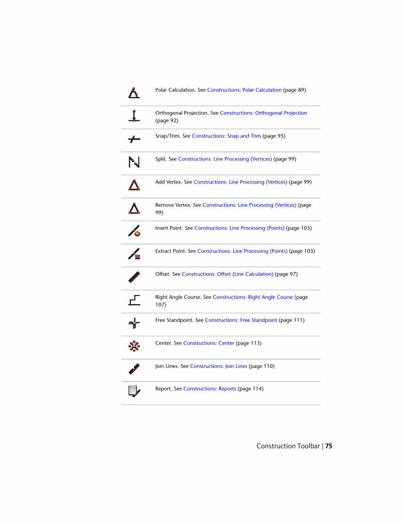
Polar Calculation. See Constructions: Polar Calculation (page 89)
Orthogonal Projection. See Constructions: Orthogonal Projection(page 92)
Snap/Trim. See Constructions: Snap and Trim (page 95)
Split. See Constructions: Line Processing (Vertices) (page 99)
Add Vertex. See Constructions: Line Processing (Vertices) (page 99)
Remove Vertex. See Constructions: Line Processing (Vertices) (page99)
Insert Point. See Constructions: Line Processing (Points) (page 103)
Extract Point. See Constructions: Line Processing (Points) (page 103)
Offset. See Constructions: Offset (Line Calculation) (page 97)
Right Angle Course. See Constructions: Right Angle Course (page107)
Free Standpoint. See Constructions: Free Standpoint (page 111)
Center. See Constructions: Center (page 113)
Join LInes. See Constructions: Join Lines (page 110)
Report. See Constructions: Reports (page 114)
Construction Toolbar | 75
Navigating the Construction Commands
Construction: General Guidelines
Keep the following in mind as you use the construction commands:
■ When you start a construction command, you are prompted to selectelements in the drawing or in the map. Always watch the AutodeskMapGuide status line!
■ All elements of the calculation (such as arcs, circles, and points) appeartemporarily in the drawing.
■ See Using Construction Tools (page 73).
NOTE The elements have to be Topobase features, which means they have to bestored in the database.
■ As soon as the required elements are selected, the focus changes to theconstruction dialog box.
NOTE If you press Esc instead of selecting an element, the construction dialogbox is displayed immediately without prompting.
■ The construction dialog box displays all construction elements, parameters,and results. For example, it displays point coordinates, radius, and distance.You can modify the parameters and calculate again. See ConstructionDialog Boxes and Menus (page 76).
NOTE Some construction functions have no dialog box. They are controlledby the command line.
■ After the re-calculation, the drawing is updated with the new result.
■ You can save the result in the database.
Construction Dialog Boxes and MenusThis illustration of the Arc Intersection dialog box shows the dialog controlsand components.
76 | Chapter 4 Construction and Calculation

Construction dialog box
Construction dialog boxes contain the following elements:
DescriptionElement
Edit to modify values.White text box
Right-click any text box in the construction dialog boxes to viewits shortcut menu.
Shortcut menu
View the results of calculations.Gray text boxes
Select the feature class to save the calculated object to (point orline string feature class). This list displays all appropriate feature
Feature Class listbox
classes for the workspace. For example, if the result is a point, itdisplays point feature classes.
Switch to the drawing and select an element. You can also acquiredistances, but not angles or orthogonal projections.
Change the element’s orientation or toggle between two possibleresults.
Navigating the Construction Commands | 77
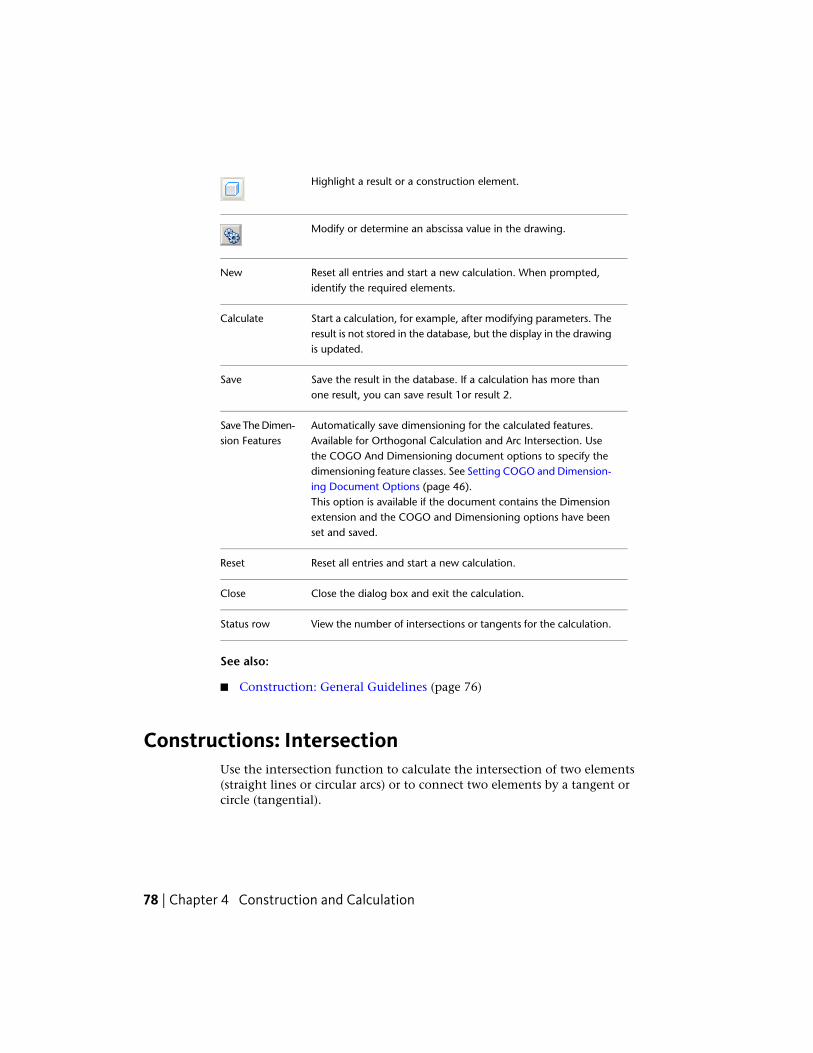
Highlight a result or a construction element.
Modify or determine an abscissa value in the drawing.
Reset all entries and start a new calculation. When prompted,identify the required elements.
New
Start a calculation, for example, after modifying parameters. Theresult is not stored in the database, but the display in the drawingis updated.
Calculate
Save the result in the database. If a calculation has more thanone result, you can save result 1or result 2.
Save
Automatically save dimensioning for the calculated features.Available for Orthogonal Calculation and Arc Intersection. Use
Save The Dimen-sion Features
the COGO And Dimensioning document options to specify thedimensioning feature classes. See Setting COGO and Dimension-ing Document Options (page 46).This option is available if the document contains the Dimensionextension and the COGO and Dimensioning options have beenset and saved.
Reset all entries and start a new calculation.Reset
Close the dialog box and exit the calculation.Close
View the number of intersections or tangents for the calculation.Status row
See also:
■ Construction: General Guidelines (page 76)
Constructions: IntersectionUse the intersection function to calculate the intersection of two elements(straight lines or circular arcs) or to connect two elements by a tangent orcircle (tangential).
78 | Chapter 4 Construction and Calculation
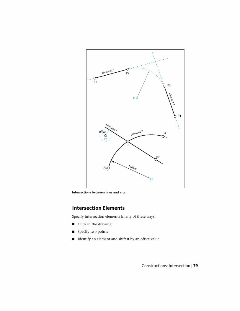
Intersections between lines and arcs
Intersection ElementsSpecify intersection elements in any of these ways:
■ Click in the drawing.
■ Specify two points
■ Identify an element and shift it by an offset value.
Constructions: Intersection | 79

■ Specify point and orientation.
Intersection Elements
Use the dialog box to modify the parameters.
DescriptionElement
Element 1 and 2 can be a straight line or a circular arc.Element 1
Click to show the element in the drawing.
Element 2
Click to identify another element in the drawing.Specify an offset value to shift the element.Specify an azimuth value to rotate the element.
The orientation of element 1 is indicated by the direction of Point 1and Point 2.
Point 1Point 2
The orientation of element 2 is indicated by the direction of Point 3and Point 4.
Point 3Point 4
Coordinates of the points. You can edit the coordinates or use to select another point.
EastingNorthingElevation
80 | Chapter 4 Construction and Calculation
Modify as needed. Use to switch between long arc and shortarc.
Radius
Use the azimuth to rotate the element. For tangents the azimuthvalue specifies in which quadrant the result is located.
Azimuth
Use to reverse the line (add 180 degrees to the azimuth value).
Intersections with arcs have more than one result.Intersection 1
Use the Tangentials to toggle between point and tangentscalculation.
Intersection 2
For tangentials, if you define tangents, you can specify a radius. Enter0 or leave the field empty to calculate a straight line.
If you define a radius you can use the Show Next to show allpossible locations of the tangential arc.
Intersection Workflow
Sample workflow for an intersection between two straight lines:
1 In Topobase Web, in the Construction toolbar, click Intersection.
2 In the map, select element 1. The element, with its determining pointsP1 and P2, is highlighted in the drawing.
3 Select element 2. The element, with P3 and P4, is highlighted. TheIntersection dialog box is displayed.
4 In the dialog box, select the feature class in which to store the intersectionpoint.
5 Click Save Inters. 1 to store the point in the database.
You can now quit or calculate other intersections.
6 Click New to reset the intersection parameters. You can now select newelements in the map.
7 Select element 1.
8 Select element 2.
Constructions: Intersection | 81
After you select element 2, the Intersection dialog box becomes activeagain. Use the dialog box to modify the intersection parameters.
9 In the Intersection 1 row, click to switch to Tangential mode.
10 Enter a radius for the tangent to be calculated.
11 Click Calculate to calculate the tangent with the modified parameters.
12 Click the Show Next to show all possible locations of the tangentialarc.
13 Select the feature class in which to store the tangent.
14 Click Save Inters. 1 to store the arc in the database.
See also:
■ Intersection Elements (page 79)
■ Constructions: Intersection (page 78)
■ Setting COGO and Dimensioning Document Options (page 46)
Constructions: Arc IntersectionUse the arc intersection function to calculate intersections of two circular arcs.You also can determine the tangents to the arcs.
82 | Chapter 4 Construction and Calculation

Arc Intersection elements
When you use Orthogonal Calculation or Arc Intersection, you optionallycreate dimensioning for the calculated points. In the construction dialog box,under Save Options, select Save The Dimension Features.
For Arc Intersection, when you calculate the tangentials, you cannot createdimensioning.
See also:
■ Setting COGO and Dimensioning Document Options (page 46)
Arc Intersection Elements
DescriptionElement
Specify the arc by a center point P1 or P2 and a radius.Arc 1Arc 2
Edit the coordinates in the dialog box or use toselect another point.
Easting, Northing
Constructions: Arc Intersection | 83

You can edit the arc radii values in the dialog box or
use to define it in the drawing.
Radius
If the intersection type is Tangentials, you can enter aradius. Set Radius to NULL or 0 for straight-line tan-gents.
Tangent
I1Intersection 1
Use to change between intersection types (Pointsor Tangentials).
Points/Tangentials
I2Intersection 2
If you calculate tangents with a radius, you can use the
Show Next to show all possible locations of thetangential arc.
Show Next
Save dimensioning for the calculated features automat-ically. Use the COGO And Dimensioning document
Save The Dimension Fea-tures
options to specify the dimensioning feature classes. SeeSetting COGO and Dimensioning Document Options(page 46).
See also:
■ Constructions: Arc Intersection (page 82)
■ Arc Intersection Workflow (page 84)
Arc Intersection Workflow
Sample workflow for intersection and tangent calculation:
1 In Topobase Web, in the Construction toolbar click Arc Intersection.
2 In the map, select the center of arc 1.
3 Select the radius of arc 1.
84 | Chapter 4 Construction and Calculation

4 Select the center of arc 2.
5 Select the radius of arc 2.
6 In the construction dialog box, select the feature class.
7 Click in the Intersection 1 row to switch the intersection type toTangentials.
8 To calculate an arc, in the Tangent line, enter a radius for the tangents.
The feature class list box now shows the available line string featureclasses.
9 Click in the Intersection 1 row to switch the intersection type toPoints.
10 From the menu bar, choose File ➤ Save to save both results.
You can now quit or calculate other intersections.
11 Click New to reset the arc intersection parameters. Select new elementsin the map.
See also:
■ Constructions: Arc Intersection (page 82)
■ Arc Intersection Elements (page 83)
Constructions: Orthogonal CalculationUse the Orthogonal Calculation function for orthogonal surveying. The baseelement is represented by either an existing line or by using two points whichcan lie aside. When the calculation is performed, measured and calculateddimensions are taken into account.
Constructions: Orthogonal Calculation | 85

Orthogonal calculation elements
When you use Orthogonal Calculation or Arc Intersection, you optionallycreate dimensioning for the calculated points. In the construction dialog box,under Save Options, select Save The Dimension Features.
You can use Orthogonal Calculation to measure distances. See Constructions:Tips and Tricks (page 115).
See also:
■ Setting COGO and Dimensioning Document Options (page 46)
Orthogonal Calculation Elements
DescriptionElement
Base line for orthogonal surveying.Element
Click to view the element in the drawing.
Click to identify another base line.
Enter an Offset value or use to shift the line.Enter a Radius value if your base line is an arc.
86 | Chapter 4 Construction and Calculation

Enter an Azimuth value or use to modify the orient-ation of the base line.
Specify the base line by two points (P1 and P2) and aradius (for a straight-line radius, enter 0).
Point 1Point 2
With a point Offset value, you can specify a base linethat is tangent to a circle with that radius.If you click a base line in the drawing, the coordinatesof the next two vertices are inserted in the dialog box.
Edit the coordinates in the dialog box or use toselect another point.
Easting and Northing
The coordinates of the calculated point.Constructed
Use to determine the abscissa and ordinate of anexisting point. This is useful for calculating another pointwith delta values.
Enter the abscissa and ordinate of the new point.AbscissaEnter negative ordinates to determine points that areleft to the base line.
Ordinate
Use in the Constructed row to transfer the valuesof an existing point into the dialog box.
Use in the abscissa or ordinate row to specify thevalue in the drawing.
Specify the values with an absolute number or withdelta values related to the current value. This is useful
ValueDelta
for calculating a number of points with the same ab-scissa or ordinate distances.Enter a delta value and click Calculate. The new valueis calculated by adding the delta to the current value.Click Calculate again to add the delta value again.
Base line propertiesDistance
Distance that was measured in the field.Measured
Constructions: Orthogonal Calculation | 87

Calculated distance of the base line points P1-P2; read-only.
Calculated
Enter a measured distance to calculate a factor, whichis used to adjust the differences between calculated andmeasured distance proportional to the abscissa values.
Factor
Abscissa value at point 1; the default is 0.00.Abscissa P1If your measurement did not start with the abscissa0.00, enter a new value.If your actual starting point is different from the indic-ated P1, use Abscissa P1 to select this point in thedrawing. If the point is not on the selected base line,the projection point is calculated.
Save dimensioning for the calculated features automat-ically. Use the COGO And Dimensioning document
Save The Dimension Fea-tures
options to specify the dimensioning feature classes. SeeSetting COGO and Dimensioning Document Options(page 46).
See also:
■ Constructions: Orthogonal Calculation (page 85)
■ Orthogonal Calculation Workflow (page 88)
■ Setting COGO and Dimensioning Document Options (page 46)
Orthogonal Calculation Workflow
Sample workflow to calculate orthogonal points:
1 In Topobase Web, in the Construction toolbar click OrthogonalCalculation.
2 In the map, select the base element. The line is highlighted in the drawingwith the abscissa values at the starting and end point. The constructiondialog box opens.
88 | Chapter 4 Construction and Calculation

3 In the construction dialog bo x, click for the Azimuth column tointerchange the start and end points.
4 To calculate new points, enter the abscissa and ordinate value and clickCalculate. The result is highlighted in the drawing.
5 To save the new point in the database, select a feature class and click SavePoint.
See also:
■ Constructions: Orthogonal Calculation (page 85)
■ Orthogonal Calculation Elements (page 86)
■ Setting COGO and Dimensioning Document Options (page 46)
Constructions: Polar CalculationUse the Polar Calculation function for polar surveying. The base element isrepresented by either an existing line or by using two points which can lieaside.
Constructions: Polar Calculation | 89

Polar calculation elements
Polar Calculation Elements
DescriptionElement
Determine the base line for polar surveying with astation P1 and a connection point P2.
Element
Click to identify another base line.
Enter an Offset value or use to shift the line.
Enter an Azimuth value or use the Azimuth tointerchange the start and end points.
P1: observing station.Point 1
P2: connecting point to determine the base line. Ifyou select a polyline, the vertices nearest to the clickare used.
Point 2
90 | Chapter 4 Construction and Calculation

Edit the coordinates in the dialog box or use toselect another point.
Easting and Northing
Specify the base line with an offset to the selectedelement.
Offset
Azimuth of the base line (angle between base lineand north).
Azimuth
Coordinates of the calculated point, target point.Constructed
Use to determine the distance and angle of anexisting point. This is useful for calculating anotherpoint with delta values.
The measured distance between the station and newpoint.
Distance
The measured angle (direction) to the new pointcalculated point (reading from field measurement).
Angle
Specify the values with an absolute number or withdelta values related to the current value. This is useful
Value;Delta
for calculating a number of points with the samedistances or angles.Enter a delta value and click Calculate. The new valueis calculated by adding the delta to the current value.Click Calculate again to add the delta again.
Enter a longitudinal offset.Longitud. Shift
Enter a lateral offset (rectangular to the P1-calculatedpoint line)
Lateral Shift
The measured angle to the base line point P2Base Angle
See also:
■ Constructions: Polar Calculation (page 89)
■ Polar Calculation Workflow (page 92)
Constructions: Polar Calculation | 91

Polar Calculation Workflow
Sample polar calculation workflow:
1 In Topobase Web, in the Construction toolbar, click Polar Calculation.
2 In the map, select the base element.
The line is highlighted in the drawing with the distance between stationand connection end point. The construction dialog box opens.
3 In the construction dialog box, click for the Azimuth column tointerchange the station and connection points.
4 Enter the base angle.
5 To calculate new points, enter the distance and angle value and clickCalculate.
The result is highlighted in the drawing.
6 To save the new point in the database, select a feature class and click SavePoint.
See also:
■ Constructions: Polar Calculation (page 89)
■ Constructions: Polar Calculation (page 89)
Constructions: Orthogonal ProjectionUse the Orthogonal Projection function to determine the orthogonal projectionpoint on lines and arcs.
92 | Chapter 4 Construction and Calculation

Projection elements
Orthogonal Projection Elements
DescriptionElement
Base line for orthogonal projection: P1 –P2
Element
Click to identify another base line.
Enter an Offset value or use to shiftthe line.Enter a Radius value if your base line is anarc.
Enter an Azimuth value or use tomodify the orientation of the base line.
If the base element is an arc (radius is not
null), use to switch between a longand short arc.
Point 1
P2Point 2
Constructions: Orthogonal Projection | 93

Edit the coordinates in the dialog box or
use to select another point.
EastingNorthingElevation
P: Point to be projected. Use to selectanother point.
Point P
Coordinates of the projected point on theline.
Projection
Length of the base element (the distancebetween P1 and P2). Enter a measured
Distance MeasuredCalculated
value to calculate a factor for adjusting theresulting abscissa.
The abscissa value of the projection line(ordinate = 0,00).
Abscissa
See Also Constructions: Orthogonal Calcu-lation (page 85)
Abscissa P1
See also:
■ Constructions: Orthogonal Projection (page 92)
■ Orthogonal Projection Workflow (page 94)
Orthogonal Projection Workflow
Sample orthogonal projection workflow:
1 In Topobase Web, in the Construction toolbar click OrthogonalProjection.
2 In the map, select the base element.
3 Select the projection point.
The construction elements are highlighted in the drawing. Theconstruction dialog box opens.
94 | Chapter 4 Construction and Calculation

4 To save the new point in the database, select a feature class and click SavePoint.
See also:
■ Constructions: Orthogonal Projection (page 92)
■ Orthogonal Projection Elements (page 93)
Constructions: Snap and TrimUse the Snap And Trim function for line feature processing. You can trim orextend a line so the end point lies exactly on a base line. This is often used tocreate correct topologies or inaccurate data acquisition.
Snap and trim elements
Snap and Trim Elements
DescriptionElement
The base line for trimming or extending,determined by points P1 and P2.
Element
Click to identify another base line.
Constructions: Snap and Trim | 95

Enter an Offset value or use the Graphicicon to shift the line.Enter a Radius value, if your base line is anarc. If the radius is not null, you can use
to switch between long and short arc.
Enter an Azimuth value or use tomodify the orientation of the base line.
P1: start point of the base line.Point 1
P2: end point of base line.Point 2
Edit the coordinates of the base line in the
dialog box or use to select anotherpoint.
EastingNorthingElevation
P: Point of the line to modify. By default,this is the first vertex of the line definition.
Point P
Use this value to switch to another vertexof the selected line. Index = 0 indicates thefirst vertex, index 1 the second, and so on.
Index
Use to select another point.Feature ID
FID of the feature to be modified.Value
The new end point of the line after the trimor snap process.
Moved P
The current feature class. The result of snapor trim overrides the existing feature.
Feature Class
See also:
■ Constructions: Snap and Trim (page 95)
■ Snap and Trim Workflow (page 97)
96 | Chapter 4 Construction and Calculation

Snap and Trim Workflow
Sample Snap And Trim workflow:
1 In Topobase Web, in the Construction toolbar click Snap.
2 In the map, select the base element.
3 Select the line feature to modify.
The elements are highlighted in the drawing. The construction dialogbox opens.
4 To save the modifications in the database, click Save Feature.
See also:
■ Constructions: Snap and Trim (page 95)
■ Snap and Trim Elements (page 95)
Constructions: Offset (Line Calculation)Use the Offset function to calculate lines with any offset, based on an existingline.
Line offset calculation
Constructions: Offset (Line Calculation) | 97

Line Offset Calculation Elements
DescriptionElement
The base line for calculations (offset =0.00).
Base Feature
Use to select another base line.
Add definition rows for the offset lines.Specify the distance to the base line byclicking.
Add
Definition rows for the offset lines.Shifted Line xClick Add to add more lines.
Use these values to extend or shorten theoffset line in relation to the base feature.
Start abscissaEnd Abscissa
Use or enter a new value.
The offset value. The initial value is spe-cified in the drawing. Edit this value, forexample, to set it to an even value.
Shift
Specify the abscissa value in the drawing.
Delete a definition row.
See also:
■ Constructions: Offset (Line Calculation) (page 97)
■ Line Offset Calculation Workflow (page 99)
98 | Chapter 4 Construction and Calculation
Line Offset Calculation Workflow
Sample Line Offset Calculation workflow:
1 In Topobase Web, in the Construction toolbar click Offset.
2 In the map, select the base line. You can select only lines that are savedin the database.
The line and its start and end point are indicated in the drawing and theconstruction dialog box opens.
3 In the construction dialog box, click Add.
4 In the map, click to specify the distance of the first offset line. Click forthe next line. Right-click to finish the entry.
5 In the construction dialog box, modify the parameters of the shiftedlines.
6 Click Calculate to see the results in the drawing.
7 Select a feature class.
8 Click Save Features to save your modifications to the database.
See also:
■ Constructions: Offset (Line Calculation) (page 97)
■ Line Offset Calculation Elements (page 98)
Constructions: Line Processing (Vertices)You can add or remove vertices of lines that are stored in the database.
NOTE These functions are controlled only by the Autodesk MapGuide status line.
Constructions: Line Processing (Vertices) | 99
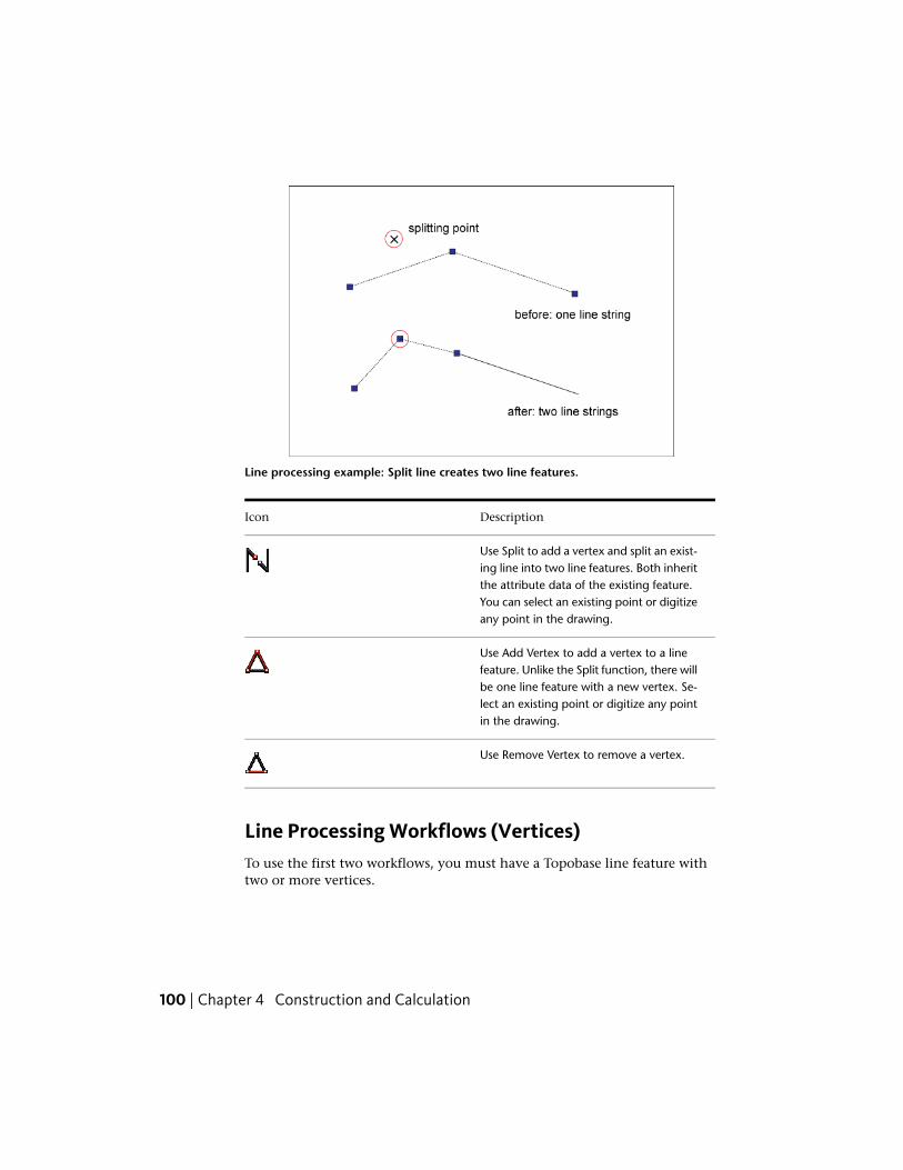
Line processing example: Split line creates two line features.
DescriptionIcon
Use Split to add a vertex and split an exist-ing line into two line features. Both inheritthe attribute data of the existing feature.You can select an existing point or digitizeany point in the drawing.
Use Add Vertex to add a vertex to a linefeature. Unlike the Split function, there willbe one line feature with a new vertex. Se-lect an existing point or digitize any pointin the drawing.
Use Remove Vertex to remove a vertex.
Line Processing Workflows (Vertices)To use the first two workflows, you must have a Topobase line feature withtwo or more vertices.
100 | Chapter 4 Construction and Calculation

Sample Split workflow:
1 In Topobase Web, in the Construction toolbar click Split.
2 In the map, select the feature to split.
3 Select or digitize the splitting point.
NOTE There are two separate line features after the calculation. Each newfeature inherits the attribute data of the old deleted feature.
Sample Add Vertex workflow:
1 In Topobase Web, in the Construction toolbar click Add vertex.
2 In the map, select the feature.
3 Select or digitize the point to insert.
Constructions: Line Processing (Vertices) | 101

Line processing example: Add vertex inserts a new vertex. The linesmove to the point.
To use this workflow, you must have a Topobase line feature with three ormore vertices.
Sample Remove Vertex workflow:
1 In Topobase Web, in the Construction toolbar click Remove Vertex.
2 In the map, select the feature.
3 Select the point to remove.
You do not need to snap the point; you can click in the neighborhoodof the vertex.
See also:
■ Constructions: Line Processing (Vertices) (page 99)
102 | Chapter 4 Construction and Calculation

Constructions: Line Processing (Points)When you process Topobase point and line features, keep in mind thedifference between a vertex and a point.
■ A vertex is a component of a line feature whose coordinates are storedwith the line feature.
■ A point is a Topobase feature, independent from lines. Every line has avertex at its start point, but point features do not necessarily have one.
The following functions consider the relation between line and point features.Use them to improve the consistency of network geometry, to create correcttopological relations, or to adjust inaccuracies due to measurement.
You can insert an existing point into a line feature and optionally split theexisting line into two line features.
You can extract an existing point from a line feature and connect the twoexisting lines into one.
NOTE These functions are controlled only by the Autodesk MapGuide status line.
DescriptionIcon
Use Insert Point to move an existing pointthat lies within a tolerance exactly on theline feature.
Use Extract Point to remove a point froma line and delete it from the database. Youcan remove the point only if it lies on astraight line within a split tolerance.
Constructions: Line Processing (Points) | 103

Points can be inserted or extracted only if they lie within the splittolerance.
Constructions: Insert PointThe Insert Point command calculates new point coordinates that lie exactlyon the line. At the insertion point, a new vertex is inserted. The vertex indicatesthe relation between point and line for further processing.
You can split the line at the insertion point. The existing line feature is deletedand two new line features are created instead. Specify whether to split a lineor not in the application options. See Setting COGO Options (page 44).
A point is inserted into a line. Its coordinates are movedto the line.
The insertion is documented in the database. An inserted point is saved witha special reliability attribute.
If the difference between the old and new position of the point exceeds thesplit tolerance, the point is not inserted and a message appears.
104 | Chapter 4 Construction and Calculation
You can set the split tolerance in the application options. See Setting COGOOptions (page 44).
You can insert a point only under certain conditions. If a condition is notfulfilled, one of the following messages appears in the command line:
■ The distance from point to line is too large: You exceeded the splittolerance.
■ There is no suitable point at the vertex before the point: You can insert apoint only if there are points at the vertices before and after the insertionpoint.
■ The line already has a vertex at this position: You cannot insert a point atan existing vertex.
■ The spatial tolerance of the selected line must be smaller than the splittolerance: The Topobase Administrator set the spatial tolerance whencreating the database.
See also:
■ Constructions: Line Processing (Points) (page 103)
Insert Point WorkflowTo use this workflow, you must have a Topobase line feature with point featuresat the start and end of the line segment and a point feature that lies withinthe split tolerance.
Sample Insert Point workflow
1 In Topobase Web, in the Construction toolbar, click Insert Point.
2 Select the line.
Watch the Autodesk MapGuide status line.
3 Select the point feature to insert.
If the conditions are fulfilled, the point is inserted. If not, a message in thecommand line informs you. The calculation is cancelled.
Constructions: Line Processing (Points) | 105

See also:
■ Constructions: Line Processing (Points) (page 103)
■ Constructions: Insert Point (page 104)
Constructions: Extract PointThe Extract Point command removes a point from a line. The point is deletedfrom the database and a new line feature is built.
You can extract a point only under certain conditions. If a condition is notfulfilled, one of the following messages appears in the command line:
Split tolerance: A point can be extracted only if it is within the split toleranceof its adjacent points (orthogonal projection on the new straight line).
The distance to the line being built is too large: The distance of the point tothe new line feature is greater than the split tolerance.
The line has no vertex at this position: You can extract a point only if thereis a line vertex at the same location. Topobase uses the vertex to detect whetherthe point has a relation to the line.
See also:
■ Constructions: Line Processing (Points) (page 103)
■ Constructions: Insert Point (page 104)
Extract Point WorkflowTo use this workflow, you must have a Topobase line feature with two segmentsand point features at each vertex. The middle vertex must lie on the straightline, within the split tolerance.
Sample Extract Point workflow:
1 In Topobase Web, in the Construction toolbar, click Extract Point.
2 Select the line.
Watch the Autodesk MapGuide status line.
3 Select the point to extract.
106 | Chapter 4 Construction and Calculation

If the conditions are fulfilled, the point is extracted. The point is deleted fromthe database and a new line is built.
If the point cannot be extracted, a message in the command line informs you.The calculation is cancelled.
See also:
■ Constructions: Line Processing (Points) (page 103)
■ Constructions: Extract Point (page 106)
Constructions: Right Angle CourseUse the Right Angle Course function to construct line definitions for buildings.At least two coordinates (existing points) must be defined. A right angle(outline size) must be measured between the known points.
You can construct the line in either of two modes:
■ Point Mode: Use two arbitrary corner points that are connected bymeasured sections.
■ Base Line Mode: Starting with two points, specify the base line for furthersections.
The Topobase Administrator can specify the construction mode in theapplication options. For more information, see the “Topobase AdministratorGuide.”
Constructions: Right Angle Course | 107
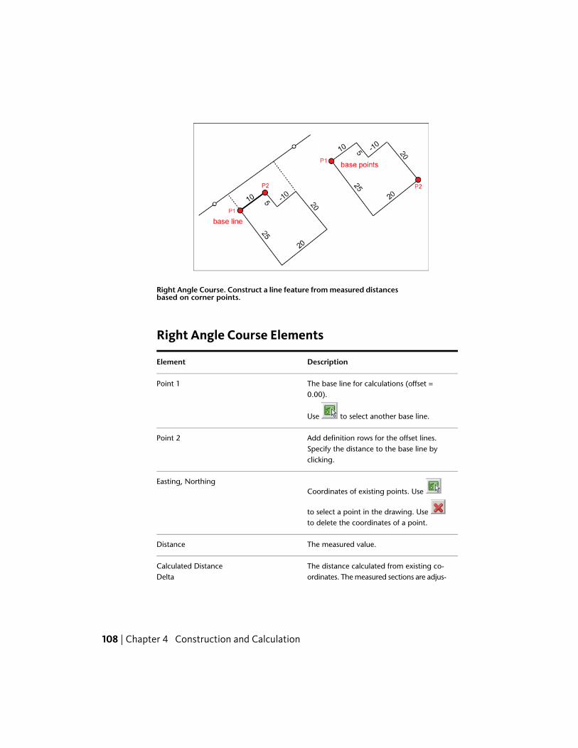
Right Angle Course. Construct a line feature from measured distancesbased on corner points.
Right Angle Course Elements
DescriptionElement
The base line for calculations (offset =0.00).
Point 1
Use to select another base line.
Add definition rows for the offset lines.Specify the distance to the base line byclicking.
Point 2
Coordinates of existing points. Use
to select a point in the drawing. Use to delete the coordinates of a point.
Easting, Northing
The measured value.Distance
The distance calculated from existing co-ordinates. The measured sections are adjus-
Calculated DistanceDelta
108 | Chapter 4 Construction and Calculation

ted to the existing points. Delta shows thedifference between measured and calcu-lated values, so you can decide, whetherthe object can be described with a rightangle course.
The right angle course can consist of anarbitrary number of measured sections and
Point 3Point …
existing points. For sections, only the dis-tance column is filled out.
Click Add Sections to enter the measuredvalues. The focus changes to the map and
Add Sections
you can specify the location with a click orenter the value.
See also:
■ Constructions: Right Angle Course (page 107)
■ Right Angle Course Workflow (page 109)
Right Angle Course WorkflowThe workflow varies, depending on the current mode. Determine the currentmode by the kind of input the program prompts you for.
If Base Line Mode is active (the default), you are prompted to select the twopoints that specify the base line. Then the dialog box opens and you cancontinue adding the measured sections.
If Point Mode is active, you are prompted to select the base point. Then thedialog box opens and you can continue with either a point or a measuredsection.
Sample workflow for base line mode:
1 In Topobase Web, in the Construction toolbar, click Right AngleCourse.
2 In the map, select the first point.
3 Select the second point.
Constructions: Right Angle Course | 109

The construction dialog box opens.
4 In the construction dialog box, click Add Sections.
5 In the map, enter the measured value.
6 Enter as many measured sections as necessary. Press Esc to return to theconstruction dialog box.
Use next to the Northing column to identify existing points.
7 Select a feature class and click Save to store the line in the database.
See also:
■ Constructions: Right Angle Course (page 107)
■ Right Angle Course Elements (page 108)
Constructions: Join LinesUse the Join Lines function to join two line features into one feature.
Join Lines Workflow
Sample Join Lines workflow:
1 In Topobase Web, in the Construction toolbar, click Join Lines.
2 In the map, select two or more lines.
3 Right-click to finish the selection of the lines.
If the selected lines are continuous, they are connected to one line feature.
See also:
■ Constructions: Join Lines (page 110)
110 | Chapter 4 Construction and Calculation

Constructions: Free StandpointUse the Free Standpoint function to calculate station summaries and freestations, or to calculate the center of three circles. Corrections and residualdiscrepancies are displayed, as well as the azimuth (orientation).
Calculation of free standpoint
Free Standpoint Elements
DescriptionElement
Constructions: Free Standpoint | 111

The coordinates and the direction are cal-culated from the measurements (distancesand directions).
Free PT
Use to highlight the point in thedrawing.
Connection points with measured dis-tances and directions.
Point 1Point 2Point …
Measurement (distance).Distance
NOTE With 3 points and 3 distances, youcan calculate the center of three circles.
The difference between the measured andcalculated distance.
Delta
The measurement (angle)Direction
The difference of directionAng. Delta
Click to add another connection point.Select the point in the drawing and enterthe measurements
Add Point
Remove a point
Select the point or item in the drawing.
See also:
■ Constructions: Free Standpoint (page 111)
■ Free Standpoint Workflow (page 113)
112 | Chapter 4 Construction and Calculation
Free Standpoint Workflow
Sample Free Standpoint workflow:
1 In Topobase Web, in the Construction toolbar, click Free Standpoint.
2 In the map, select the connection points for your distance and directionmeasurements.
3 Right-click to finish the selection of the connection points.
4 In the construction dialog box, enter the measurements.
5 Click Calculate.
6 Select a feature class and click Save to store the point lines in the database.
See also:
■ Constructions: Free Standpoint (page 111)
■ Free Standpoint Elements (page 111)
Constructions: CenterUse the Center function to determine the center of an arbitrary number ofsource points. You do not have to have saved source points in the database.The result can be saved in the database.
Center Elements
DescriptionElement
The coordinates of the calculated centerpoint.
Center
Source points.Point 1
Use to select another point.Point …
Click Add Point to add one or more sourcepoints.Click Calculate to see the modifications.
Constructions: Center | 113

Remove a point from the calculation.
Select the point in the drawing.
See also:
■ Constructions: Center (page 113)
■ Center Workflow (page 114)
Center Workflow
Sample Center workflow:
1 In Topobase Web, in the Construction toolbar, click Center.
2 In the map, select or digitize the points.
3 Right-click to finish the selection of points.
4 Select a feature class and click Save to store the point in the database.
See also:
■ Constructions: Center (page 113)
■ Center Elements (page 113)
Constructions: Reports
Use to print reports of your constructions. You can select by differentcriteria, for example, job or date.
DescriptionConstruction Report
Select the job.Job
Select the date range.FromTo
114 | Chapter 4 Construction and Calculation

Select a report definition.Report
Show a preview. You can then print thereport or export it to any available fileformat.
Preview
To print a construction report
1 In Topobase Web, in the Construction toolbar, click .
2 Select a job, for example, Live.
3 Select a time period.
4 Select a report, for example, Intersection.
5 Click Preview.
6 In the Topobase Report Preview dialog box, examine the report and itslayout.
7 Send the report to the desired output target, for example, a printer or afile.
See also:
■ Using Construction Tools (page 73)
■ Navigating the Construction Commands (page 76)
Constructions: Tips and TricksUse Document Options to remove the temporary construction feature classesfrom the database. Use Orthagonal Calculation to measure distances.
To remove temporary construction feature classes
1 Click Document ➤ Document Options.
2 Select COGO.
While you are running the construction functions, you can acquire distancesand projections.
Constructions: Tips and Tricks | 115

To measure a distance
1 Start Orthogonal Calculation.
2 Use for the Constructed Point to measure the ordinate and abscissaof a point.
3 Use the P1 to measure the projection of a point on the base line.
See also:
■ Setting Document Options (page 45)
■ Constructions: Orthogonal Calculation (page 85)
116 | Chapter 4 Construction and Calculation

Glossary
area topology Description of spatial relationship between geographic area features. Areatopologies contain line strings and centroids. In Topobase™, the polygons are generatedautomatically from the surrounding line strings. Examples of area topologies are parcels, landuse, land cover and political boundaries. See also Topology.
centroid A point that indicates a polygon (approximately in the center). In Topobase, centroidsare part of area topologies and belong to the surrounding edges (line string feature class). Thecentroid normally holds the polygon's attribute data. See also Area Topology.
COGO Abbreviation for Coordinate Geometry. COGO functionality provides calculationroutines, such as for intersection, projection, orthogonal survey, offset lines, and right anglecourse.
Display Manager For stylization in Autodesk Map 3D, applies custom styles to selectedfeatures and objects. To view the Display Manager task, select Display Manager in the list atthe top of the Task Pane. Also used for stylization of Topobase features.
display model In Topobase, you use display models to administer thematic views. A displaymodel definition specifies which set of layer files (feature layers) is loaded into the DisplayManager. Also, the display model defines multi map windows and autoload layers.
document In Topobase, a document is an Oracle® database schema with additional settingsin the Topobase System user (database server schema TBSYS). A document is an Oracle databaseuser plus settings for menu bars, toolbars and forms. A document must be assigned to aworkspace to be accessible by Topobase Client or Topobase Web. You can create, edit, andconfigure the documents using the Topobase Administrator.
document explorer Control element in the Topobase Client task pane and in the TopobaseWeb layout. Use the tree view to show the objects that are stored in the database. For differentrequirements and more clarity these objects can be grouped into explorer groups. Provides adocument-specific view to process the following objects: Topics (and feature classes), domains,topologies, intersections, system tables, and workflows. You can define a different documentexplorers for each document. Also called Topobase explorer.
5
117
domain Sets of values. For example, a domain defines the values that are allowed for afeature attribute. Topobase data models store domains in domain tables (*_TBD). Domaintables are created using the Topobase data model administrator.
explorer group In Topobase Administrator, a configuration that specifies which objects areto be shown in the document explorer. These settings are saved as Explorer Groups.
feature In Topobase, an entity of a feature class. Each feature in a feature class represents arow or record in the feature class table.
feature class In Topobase, the basic class for objects. For example, a parcel is a feature class.In a database, each feature class corresponds to one Oracle table. A feature class can haveany number of attributes (Oracle columns), one of which can be of type "geometry". Thereare general types of feature classes, such as the following:
■ Attribute (feature class without geometry)
■ Line String
■ Polygon
■ Point
■ Centroid
■ Label
■ Compound Polygon
■ Compound Linestring
You can group several feature classes for each topic. Each feature class contains manyentities/instances or records, which are called features.
feature class form Database form to view and edit attribute data stored in Topobase. Formscan be customized with the Topobase form designer.
feature explorer Control element used to display a set of features in a tree view, resultingfrom a selection, a validation, or a tracing.
graphic connection A connection between Topobase and Autodesk Map or AutodeskMapGuide to display the features. Topobase Client has a graphic connection to AutodeskMap. Topobase Web has a graphic connection to Autodesk MapGuide.
job perimeter Spatial area where a job can be processed. You can use job perimeters tocontrol where the modifications of the current job is allowed. Features outside the jobperimeter cannot be processed. Also, you can define feature rules to be applied on the objectswithin the perimeter.
118 | Chapter 5 Glossary

label In Topobase, any attribute data of a feature can be displayed as text, using label features.Label features are generated by arbitrary select statements that can be defined by the customerand therefore are a flexible way to add inscriptions to the objects. Label definitions (selectstatements and other settings) are stored in the system table TB_LABEL_DEF. Label definitionscan be created or edited using the Topobase data model administrator. Label features canbe stylized with the Display Manager by displaying the LABEL_TEXT property.
label definition Select statements that create labels. The label definition 1) queries datafrom the database and 2) specifies positioning and text orientation. This information is usedin the Display Manager for stylization.
label feature class Feature class type used to store label features in the database <featureclass name>_TBL. Each feature class (parent feature class) can have exactly one label featureclass. The label feature class contains default attributes only, and contains no other specificattributes. It stores a relation to the parent feature class.
label placer Places a label to generate a label feature, to write information into the drawingor the map.
logical topology Description of the relationship of features of any feature classes, bothattribute or geometry feature classes. The features need not to be spatially connected. Forexample, a logical topology connects points with points, lines with lines,lines to points, orattribute features to attriute features. Utility networks are based on logical topologies thatconnect points (nodes) and lines (edges).
For example, a logical topology can represent a waste water network or electrical transmissionlines.
master-detail form Type of feature class form where related records are shown in anembedded sub-form on one or more tabs.
network topology See logical topology.
Polygon Object built of line segments that form an enclosed area. In Topobase, polygonsare stored in a polygon feature class.
Position Finder Finds the location of a certain object, such as a building, a parcel, or anyother type of feature that has geometry. The geometry found will be the center of a graphicgeneration or a zoom GoTo. There are several types of search such as Sequential search andFlat search.
profile In Topobase, a longitudinal section of line features. A profile is created by projectingfeatures on an axis.
profile data model Data model consisting of a set of profile system tables and an arbitraryset of profile feature classes. Profile system tables store the basic configuration and settings.Profile feature classes store the components of each profile drawing.
| 119

prototype drawing Drawing that stores all used blocks, symbols, regular and other lines,text styles and dimensioning styles.
schema plan A schematic diagram that represents real world features by transforming theoriginal feature geometry to an alternative location, for example by applying a coordinateoffset. The schema plan represents the real world features in a clear structure, and preservestopology. A schema plan can either be displayed as overlay to the original features, or in asecondary window. You use Topobase Administrator to define schema plans.
schematic feature In Topobase, schematic features are derived from real world features.They are stored in the database and are used to draw the schema plan. Each schematicfeature is associated to its real world feature.
TBMAIN Topobase Main User, which is a Topobase System User with restricted rights. Thedefault name for the Topobase Main User is TBMAIN. To start the application,non-administrator users can optionally connect to the Topobase Main User.
TBSYS Topobase System User. Topobase system database schema. Topobase server componentthat stores application settings and server-side stored procedures. The default name for theTopobase System user is TBSYS. Application users must be connected to the Topobase Systemuser or to the Topobase Main User TBMAIN to start the application.
template In Topobase, a template is an arrangement of recurrent features. The arrangementincludes feature attributes, geometry and connectivity. In Topobase Client, you use templatesto place a feature arrangement in one single step.
topic In Topobase, a group of several feature classes. A topic is a collection of feature classtables. Topics can be thought of as containers used to organize feature classes. Consideringa data transfer, topics are fully independent of one another. Each topic may have sub-topics.
To build a clear and transparent data structure, you can group feature classes into topics,group several topics into main topics, and define feature classes with sub-feature classes.These relations between topics and feature classes serve only as an illustration of the datastructure. There is not necessarily an actual relation between the tables.
Topobase Administrator A Topobase basic module, used for Topobase administration.Topobase Administrator contains several components, such as:
■ Topobase data model administrator
■ Topobase form designer
■ Topobase report designer
■ Topobase job administrator
120 | Chapter 5 Glossary

Topobase Client A component of Topobase Administrator, used for registering andprocessing data stored in Topobase through forms and using Autodesk Map for graphicprocessing.
Topobase data model administrator A Topobase module used to process and establishdata structures (topics, tables, attributes, topologies, and intersections) in Topobase. Also,you can define label definitions and dimensioning.
Topobase job All changes in the Topobase data pool can be controlled and performed byexact reports on appropriate processing steps, if they are performed inside a job. Using jobsallows you to control the version. A job includes various processing states (live, pending,project). For each processing state, an application exactly defines which actions are allowed.
Topobase System User Database schema that stores application settings and server-sidestored procedures. Default name is TBSYS. Application users must be connected to theTopobase System User to start the application. They can either connect directly to theTopobase System User or use a Topobase Main User which has restricted rights. See alsoTBSYS and TBMAIN.
Topobase Web The web version of Topobase applications.
topology A geometric shape property in which metrical relations play no role. Topologydescribes how lines, nodes, and polygons connect and relate to each other, and it forms thebasis for spatial analysis as network tracing. In Topobase, topologies can be administeredwithin individual groups of feature classes. They can be defined with the Topobase datamodel administrator.
topology checker Tool to check topologies. The results are displayed in a tree view,displaying all feature errors.
user A person who works with any Topobase application. Each application user belongs toa group called a user group, with certain tasks and rights. Examples of users: Mr. MILLER,Mr. SMITH, Ms. BAKER; BILLY, TONY, LARRY.
user group A group of users having certain task and rights. Examples of user groups: ADMIN,VIEWER, EDITOR, and so on. A member of a user group can access workspaces only if hehas a permission. He may use certain tools and functions and he has certain rights to editor view the data.
utility model Topobase data model component for utility applications, which providesfeature classes and rules for utility networks.
viewport Area of interest for the generate graphic process. A Topobase viewport is a spatialfilter on the map.
| 121

workflow In Topobase applications, a guide for the user through tasks like acquisition,analysis, and reports.
workspace The central workflow unit in Topobase. For different user groups, such as EDITOR,VIEWER or ADMIN, you can define the appropriate workspaces, with respective roles andrights. A workspace comprises one or more documents.
From the user’s point of view, a workspace is the starting point of his work. He must opena workspace to work with any Topobase application. By selecting a workspace, he will loadall necessary objects, including the appropriate menus and toolbars, with a single mouse-click.Therefore, he can even access data from different applications, such as land managementand wastewater, in arbitrary combinations.
122 | Chapter 5 Glossary

Index
A
abscissa (for orthagonal survey) 86add vertex
construction workflow 100analysis
network 67application options
setting 42application window
basic layout 4flexible Fusion layout 7
arc intersectionconstruction workflow 84constructions 82elements 83
area topologies 63checking 64
Area Topology Checker dialog box 64Autodesk Topobase Web
basic layout 4flexible Fusion layout 7overview 1starting 3tools 4, 7viewers 1
automatic job conflict validation 58azimuth
for polar calculation 90azimuth (for orthagonal survey) 86
B
buildingcalculate outline 107
C
calculationssetting precision for 44
centercalculating for three circles 111construction workflow 114coordinates 113
center construction 113centroids
finding missing 64chronological order
viewing jobs by 51circle
calculate connecting 78circles
calculating the center of three 111COGO
dialog box controls 76tools for 73
COGO and dimensioningoptions 45
COGO featuresoptions for 46
COGO optionssetting 44
COGO toolbar 32concurrent jobs
and job states 57resolving conflicts 58
configurationconstructions 73
conflict managementjobs 58
construction featuresoptions for 46
Construction toolbar 4, 7, 32, 74constructions
about 73arc intersection 82calculating center coordinates 113center of three circles 111command icons 74dialog box controls 76extract point 103extract points 106
Index | 123

feature class 73free standpoint 111general guidelines 76insert point 103–104intersection 78join lines 110line offset calculation 97line processing (points) 103line processing (vertices) 99orthogonal calculation 85orthogonal projection 92polar calculation 89polar surveying 89projection 92removing temporary feature
classes 115reports 114right angle course 107setting up 73snap and trim 95split lines 104vertices 99
coordinate geometrytools for 73
creatingfeatures with attribute data 29features without attribute data 29jobs 53labels 33templates for features 30
D
datavalidating 34
data acquisitiontemplates
reference records 37using reference records 37
Data Checker 34date
searching 40deleting
features 32Digitize Inner Ring 35Digitize New Feature 35
Digitize New Geometry For SelectedFeature 35
digitizingfeatures with templates 30
dimensioning 23options for 46
dimensioning (COGO) 73, 78distances
measuring 115Document Explorer 12document options 45
E
editingfeatures 30
Electric Explorer 16electric explorer options 45electric module 18electric options 47Excel
exporting to 27explorers 4, 7
Document Explorer 12Electric Explorer 16Workflow Explorer 14
exportingfeature data 27to Excel 27
expressionsfilter 39
extract pointconstruction workflow 106
extract point construction 106
F
feature class form toolbar 35feature classes
removing temporary constructionclasses 115
setting options for 43feature data
editing 30exporting 27
124 | Index
feature explorerzoom factor for highlighting 43
featureschecking data 34creating 29deleting 32digitizing with templates 30editing 30filtering related records 42labelling 33locating 20locating with Position Finder 21locking 58spatial selection 41splitting 33templates for 30unlocking 58
Filter Manager 40filtering
jobs 54filters
additive and OR 38expressions for 39reusing 40saving 40SQL 38tools 38using projections 42
formsfilter mode 38toolbar 35
free standpointconstruction workflow 113elements 111
free standpoint construction 111Fusion layouts 1
G
gas module 18global update 36
H
Hard Split 33
historical viewfor jobs 60
I
inconsistent datarepairing 34
insert pointconstruction workflow 105
insert point construction 104Inspection Editor 16intersection
construction workflow 81constructions 78
intersectionsperforming 34
J
Job Conflict Explorer 58job conflicts
resolving automatically 58resolving manually 58
Job control 49Job Explorer 50
using to check for job conflicts 58Job Manager 51
using to check for job conflicts 58job options 43jobs
and Topobase Web 49changing the state of 57conflict management 58creating 53defining the perimeter 53deleting modifications 56filtering 54historical view 60lease options 43leasing 60making available to other
applications 60perimeter 43processing 50selecting 49, 54toolbar 50
Index | 125

transition 57viewing by chronological order 51viewing by state 51viewing for current document 51viewing modifications 50workflow for 52
join linesconstruction workflow 110constructions 110
L
labelsadding to features 33redirecting to parent feature 43
lateral offsetfor polar calculations 90
layoutsbasic 1flexible Fusion 1
lease options (jobs) 43leasing
jobs 60Legend tab 7line definition
creating right angle 107reports 27
line offsetconstructions 97
line offset calculationconstruction workflow 99elements 98
line processingconstruction workflow 100
linesadd vertices 99joining 110remove vertices 99splitting 33trim 95
locatingfeatures in map 20features with Position Finder 21
locking features 58logical topologies 63
checking 66
login pagefor Topobase Web 3
longitudinal offsetfor polar calculations 90
M
map options 43maps
plotting 24markup 22–23multi-user
public reference records 37
N
named projections 42network analysis 67network topologies 63
checking 67network topology
line processing 103Network Tracer dialog box 67New Record 35
O
offsetcalculating lines with 97
optimistic feature locking 58options
COGO 44COGO and dimensioning 45COGO features 46dimensioning 46document 45electric 47jobs 43map 43setting application options 42wastewater 47
orthagonal surveyselements 86
orthogonal calculationconstruction workflow 88
126 | Index
orthogonal projection 92elements 93workflow 94
orthogonal surveying 85overlay functions 34
P
partial posting (jobs) 50perimeter
defining for a job 53display options 43
pessimistic feature locking 58Plot Library 24plot templates 24point features
setting options for 43points
digitizing and splitting lines 33extracting 106inserting 104options for insertion 44
polar calculationconstruction workflow 92elements 90
polar surveying 89polygon/line definition
reports 27Position Finder 21precision
setting for calculations 44printing
construction reports 114maps 24reports 26
projectionconstruction workflow 94constructions 92
projections (forms) 42propagation
see tracing 67public reference records 37
Q
quality checking 34
R
radius (for orthagonal survey) 86records
filtering related 42updating globally 36
redlining 22reference records
adding data with 37working with - 37
related featuresshowing 42
reliabilityoptions for 44
remove vertexconstruction workflow 100
Report dialog box 26reports
constructions 114polygon/line definition 27printing 26
reusingfilters 40
right angle course 107construction workflow 109setting the mode 44
right angle course constructionelements 108
S
savingfilters 40
searchingusing filters 38
Select Perimeter dialog box 53selecting
jobs 54spatial 41
Set Flow dialog box 70settings
for construction tools 73snap and trim
construction workflow 97snap and trim constructions 95
Index | 127

snap radiussetting 43
Soft Split 33spatial selection 41split
options for 44split lines
construction workflow 100constructions 99tolerance 104
split lines construction 104split tolerance
setting 44splitting
features 33SQL filter (forms) 38station summary 111stop condition
for network topologies 67
T
tangentsconstructing 78
Task Pane 4, 7templates
data capture 37digitizing features with 30for data capture (reference
records) 37for features 30for plotting 24viewing defihnitions for 30
temporary markup 22–23toolbars
construction 74Construction and Calculation 32feature class forms 35Job Explorer 50
toolsconstruction 73
Topobase Electric 18Topobase Gas 18Topobase report 26Topobase Wastewater 16Topobase Water 19
Topobase Weband jobs 49overview 1starting 3viewers 1
topologieschecking area 64checking logical 66checking network 67setting options for jobs 45
topologyoverview 63validating 64, 66–67
Topology Checker dialog box 66tracing 67Tracing Result dialog box 67trim lines 95
U
undomodifications to a job 56
unlocking features 58updating globally 36URL
for Topobase Web 3
V
validating data 34vertex
adding 99removing 99
vicinity for digitizing pointssetting 43
viewingjobs historically 60
W
wastewater module 16wastewater options 45, 47water module 19Workflow Explorer 14
128 | Index
workflowsadd vertex 100center construction 114extract point 106free standpoint 113insert point 105jobs 52join lines 110line offset calculation 99orthagonal survey 88orthogonal projection 94
polar calculation 92projection 94remove vertex 100right angle course construction 109snap and trim 97split line 100
Z
zoomfactor for feature highlighting 43
Index | 129

130