autoclave es-215, es-315 - revodix.co.kr · inside the tomy autoclave es-215/315 is subject to very...
TRANSCRIPT

O P E R A T O R ' S M A N U A L
ES-215, ES-315AUTOCLAVE
Research Use Only
TOMY SEIKO CO.,LTD.
*Before starting operation, read this Operator’ s Manual thoroughly for a complete
understanding of the autoclave and its correct handling.
*Be sure this Operator’ s Manual is within easy reach and is secure so that the operator can
consult it at any time.

1
TABLE OF CONTENTS1. FORSAFEOPERATION P.2 1-1.WARRANTYINFORMATION P. 2 1-2.WARNING/CAUTION P.3
2. OUTLINEANDFEATURESOFDEVICE P.6 2-1.OPERATINGPRINCIPLE P. 6 2-2.NAMEANDFUNCTIONOFEACHPART P.7
3. INSTALLATION P.11 3-1.RELOCATIONANDINSTALLATION P.11 3-2.POWERSUPPLYCONNECTIONANDPROPERGROUNDING(EARTHING) P.12
4. FLOWOFOPERATION P.13
5. HOWTOOPERATE P.14 5-1.TURNINGON/OFFTHEPOWERSUPPLYSWITCH P.14 5-2.OPENING/CLOSINGTHECHAMBERLID P.15 5-3.CHECKINGTHEPRESSUREGAUGE P.16 5-4.CHECKINGTHEEXHAUSTBOTTLE P.16 5-5.CHECKINGTHESTERILIZINGWATER P.17 5-6.PLACINGTHEMATERIALTOBESTERILIZED P. 1 8 5-7.SELECTINGTHEOPERATINGMODE P. 2 0 5-8.SETTINGTHEOPERATINGCONDITIONS P. 2 1 5-9.STARTINGTHEOPERATION P. 2 2 5-10.COMPLETINGTHEOPERATION P. 2 3 5-11.REMOVINGTHESTERILIZEDMATERIAL P. 2 3 5-12.DRAININGTHESTERILIZINGWATER P. 2 4
6. CONVENIENTFUNCTIONS P. 2 5 6-1.STERILIZING/WARMINGMODE P. 2 5 6-2.HEATINGMODE P. 2 7 6-3.MEMORYFUNCTION P. 2 8 6-4.TIMERFUNCTION P . 2 9
7. MAINTENANCEANDADJUSTMENT P. 3 0 7-1.CLEANINGANDDISINFECTINGTHEMAINUNIT P. 3 0 7-2.REPLACINGBELLOWS P. 3 1 7-3.WEEKLYMAINTENANCE P. 3 2
8. TROUBLESHOOTING P. 3 4 8-1.PROBLEMSANDCOUNTERMEASURES P. 3 4 8-2.ERRORCODETABLE P. 3 5 8-3.TOCONTACTUS P . 3 6
9. SPECIFICATIONS P. 3 7 9-1.SPECIFICATIONSOFDEVICE P. 3 7
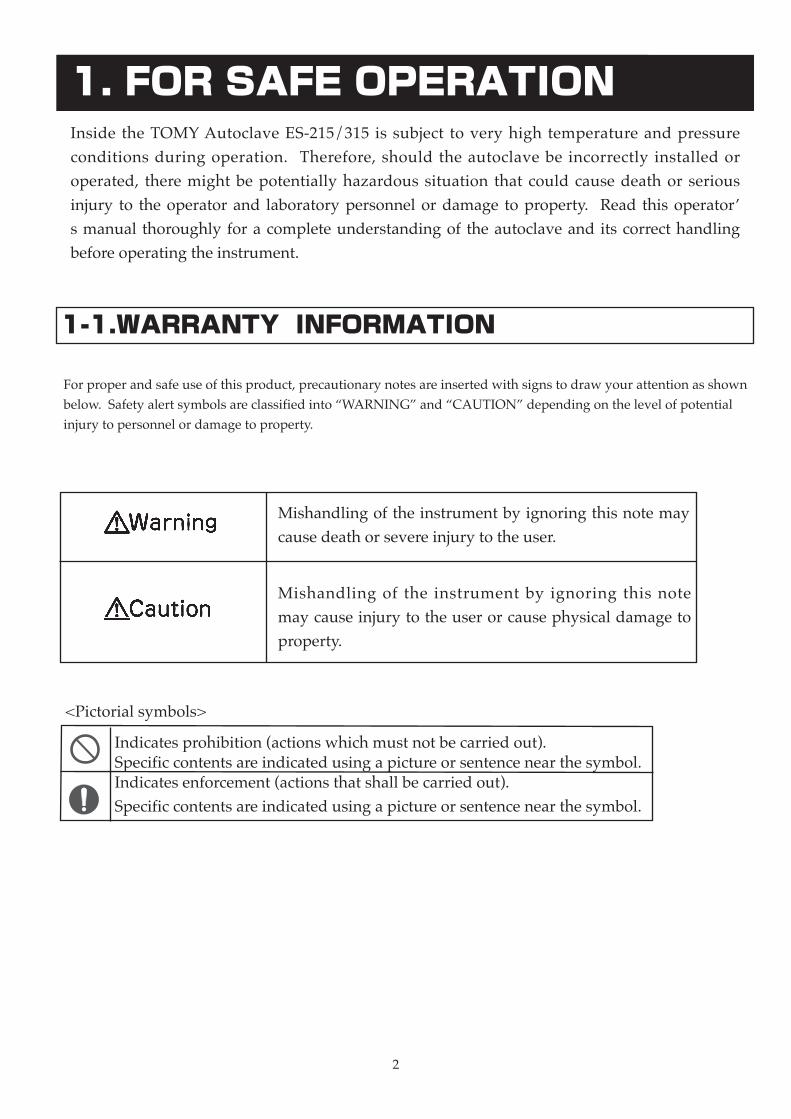
Indicatesprohibition(actionswhichmustnotbecarriedout).Specificcontentsareindicatedusingapictureorsentencenearthesymbol.Indicatesenforcement(actionsthatshallbecarriedout).Specificcontentsareindicatedusingapictureorsentencenearthesymbol.
2
Inside theTOMYAutoclave ES-215/315 is subject tovery high temperature andpressureconditions duringoperation. Therefore, should theautoclave be incorrectly installedoroperated, theremightbepotentially hazardous situation that could cause death or seriousinjury to theoperatorand laboratorypersonnelordamage toproperty. Read thisoperator’smanual thoroughlyforacompleteunderstandingof theautoclaveanditscorrecthandlingbeforeoperatingtheinstrument.
1. FOR SAFE OPERATION
<Pictorialsymbols>
Forproperandsafeuseofthisproduct,precautionarynotesareinsertedwithsignstodrawyourattentionasshownbelow.Safetyalertsymbolsareclassifiedinto“WARNING”and“CAUTION”dependingonthelevelofpotentialinjurytopersonnelordamagetoproperty.
1-1.WARRANTY INFORMATION
Mishandlingoftheinstrumentbyignoringthisnotemaycausedeathorsevereinjurytotheuser.
Mishandling of the instrument by ignoring this notemaycauseinjurytotheuserorcausephysicaldamagetoproperty.
3
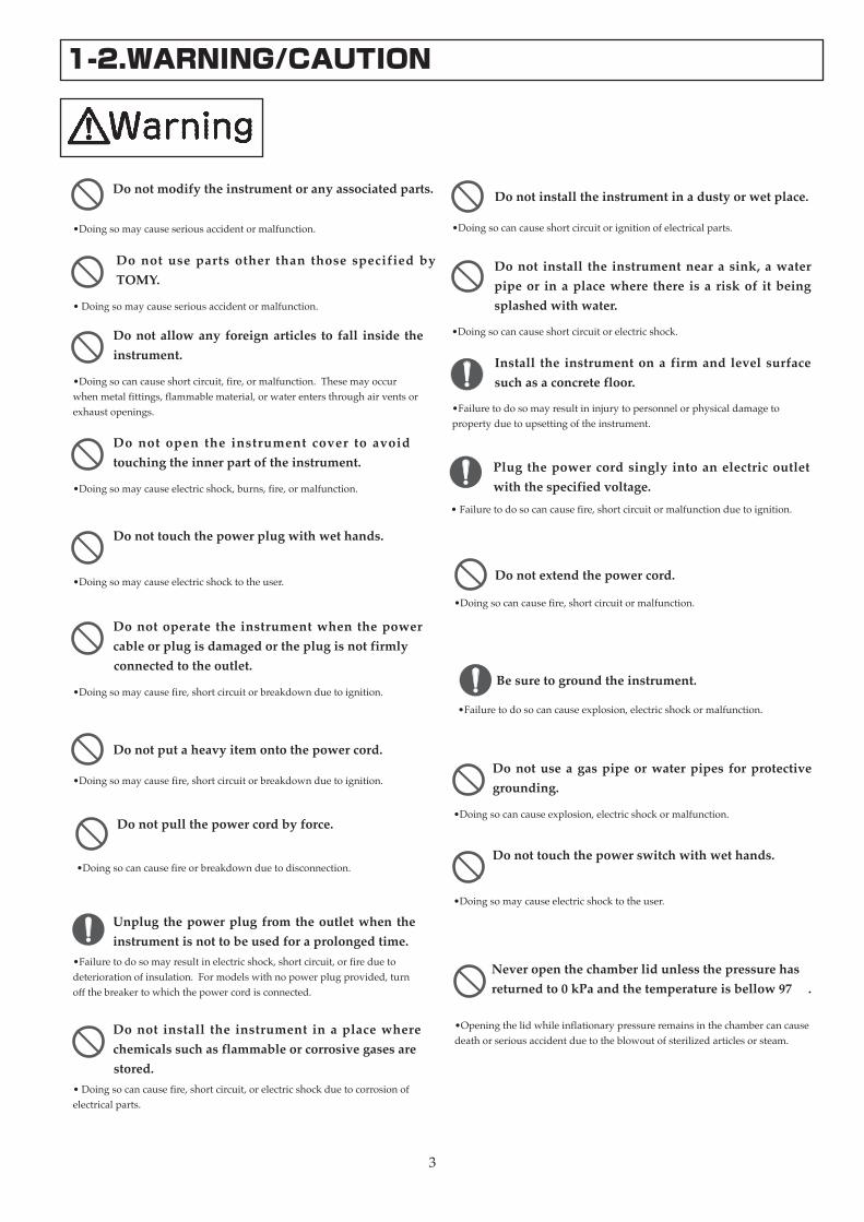
Do not modify the instrument or any associated parts.
•Doingsomaycauseseriousaccidentormalfunction.
Do not use parts other than those specified by TOMY.
•Doingsomaycauseseriousaccidentormalfunction.
Do not allow any foreign articles to fall inside the instrument.
•Doingsocancauseshortcircuit,fire,ormalfunction.Thesemayoccurwhenmetalfittings,flammablematerial,orwaterentersthroughairventsorexhaustopenings.
Do not open the instrument cover to avoid touching the inner part of the instrument.
•Doingsomaycauseelectricshock,burns,fire,ormalfunction.
Do not touch the power plug with wet hands.
•Doingsomaycauseelectricshocktotheuser.
Do not operate the instrument when the power cable or plug is damaged or the plug is not firmly
connected to the outlet.
•Doingsomaycausefire,shortcircuitorbreakdownduetoignition.
Do not put a heavy item onto the power cord.
•Doingsomaycausefire,shortcircuitorbreakdownduetoignition.
Unplug the power plug from the outlet when the instrument is not to be used for a prolonged time.
•Failuretodosomayresultinelectricshock,shortcircuit,orfireduetodeteriorationofinsulation.Formodelswithnopowerplugprovided,turnoffthebreakertowhichthepowercordisconnected.
Do not install the instrument in a place where chemicals such as flammable or corrosive gases are
stored.•Doingsocancausefire,shortcircuit,orelectricshockduetocorrosionofelectricalparts.
Do not install the instrument in a dusty or wet place.
•Doingsocancauseshortcircuitorignitionofelectricalparts.
Do not install the instrument near a sink, a water pipe or in a place where there is a risk of it being splashed with water.
•Doingsocancauseshortcircuitorelectricshock.
Install the instrument on a firm and level surface such as a concrete floor.
•Failuretodosomayresultininjurytopersonnelorphysicaldamagetopropertyduetoupsettingoftheinstrument.
Plug the power cord singly into an electric outlet with the specified voltage.
•Failuretodosocancausefire,shortcircuitormalfunctionduetoignition.
Do not pull the power cord by force.
•Doingsocancausefireorbreakdownduetodisconnection.
Do not extend the power cord.
•Doingsocancausefire,shortcircuitormalfunction.
Be sure to ground the instrument.
•Failuretodosocancauseexplosion,electricshockormalfunction.
Do not use a gas pipe or water pipes for protective grounding.
•Doingsocancauseexplosion,electricshockormalfunction.
Do not touch the power switch with wet hands.
•Doingsomaycauseelectricshocktotheuser.
Never open the chamber lid unless the pressure has returned to 0 kPa and the temperature is bellow 97℃ .
•Openingthelidwhileinflationarypressureremainsinthechambercancausedeathorseriousaccidentduetotheblowoutofsterilizedarticlesorsteam.
1-2.WARNING/CAUTION

Make sure the chamber lid is securely closed before starting operation.
•Failuretodosomaycauseburnsastheunexpectedhotsteamisescapingthroughspacebetweenthelidandthechamberunit.
4
Use caution when opening the chamber lid.
•Failuretodosomaycauseburnsorinjurybecausethesteamemanatingfrominsidechamberhasanextremelyhightemperature.
Stop operating the instrument when the pressure gauge is not working normally.
•Iftheoperatingconditionsinsidechambercannotbemonitoredcorrectlywiththepressuregauge,itcancausehazardoussituations.ContactyourdealerorthenearestTOMYofficeforrepairs.
Do not open the front door while the instrument is running to avoid touching inside front panel.
•Doingsomaycauseburnsasinsidefrontpanelissuperheated.Improperoperationoftheinstrumentmayalsocausetheblowoutofthehotwaterorsteamandresultinhazardoussituations.
Do not bend the exhaust hose.
•Doingsomayresultintheabnormalincreaseofpressureinsidechamberbecausetheairexhaustioncannotbecarriedoutsmoothly.Itcancausedamagetoparts,burns,injuryorseriousaccidentduetoexplosivebreakage.
Do not put inflammable or explosive substance inside the instrument.
•Doingsocancausefireorexplosion.
Do not sterilize sealed materials.
•Doingsomayresultinanexplosionofsuper-heatedmaterialwhenitisremovedfromthechamberandcauseburnsorseriousaccident.Itmayalsoresultintheabnormalincreaseofpressureinsidechamberandcancausedamagetoparts,burnsorseriousaccidentduetoexplosivebreakage.
Do not sterilize glass equipments having cracks or scratches.
•Doingsomayresultinanexplosionofglassequipmentwhenitisremovedfromthechamberandcauseburnsorseriousaccident
Do not operate the instrument without storing the material to be sterilized in the chamber basket (a stainless steel basket with slatted bottom plate).
•Ifthebasketisnotused,itmaycauseanexplosionofthechamberastheexhaustholeisblockedbysuchmaterialsasasterilizingbagandthepressureinsidethechambercannotbecontrolled.
Immediately stop running the instrument when the pressure enters the red zone on the indicator gauge during operation.
•Failuretodosomaycausedamagetotheinstrumentpartsorburnsandseriousaccident.TurnofftheinstrumentimmediatelyandcontactyourdealerorthenearestTOMYofficeforaninspection.
When operating the instrument in constant run mode, take more than 10 minutes interval between
running after the chamber temperature drops to 60℃ or below.
•Failuretodosomayresultinanexplosionthatcancauseburnsorinjuryordamagetotheinstrumentpartsasthepressureinsidethechamberrisesabnormallyhigh.
Use extreme caution when handling autoclaved liquids since they are hot and may suddenly boil
over.
•Thetemperatureofautoclavedliquidsfallsmoreslowlythanthetemperatureinsidechamber.Superheatedliquidsmaysuddenlyboilwhenmovedortouched.Aneruptionmayresultinburnsorseriousaccident.
Do not leave inside the chamber or sterilizing water contaminated.
•Doingsocancausecorrosionordamagetothechamber.Itmayalsocausemalfunctionofthewaterlevelsensortopreventthechamberfromheatingwithnoorlowwaterinsideandfirecanbeoccurredbyblankheating.
When executing maintenance sequences, be sure to unplug the instrument first to avoid electric shock.
•Formodelswithnopowerplug,turnoffthebreakertowhichthepowercordisconnected.
Stop running the instrument if corrosion, damage or deformation is found in the chamber, chamber lid,
lid arm or lid arm guide. •Failuretodosocancausedeath,injuryorseriousaccidentduetotheexplosionofthechamberwhilepressureisrising.Ifanyabnormalityisfoundinthechamberunit,contactyourdealerorthenearestTOMYoffice.

5
Stop running the instrument if such damage as cracks or leaks is found on the chamber lid gasket.
•Failuretodosocancauseburnstotheuserasthehotsteamescapesthroughthecrack.ContactyourdealerorthenearestTOMYofficeforaninspection.
Do not unnecessarily pull the lid gasket out of the chamber lid or deform it.
•Doingsocancauseburnstotheuserduetothehotsteamescapingthroughthelid.
Clean and decontaminate the instrument or the parts before returning it to your dealer or TOMY, shipping it back for service, or allowing a service technician
to repair it whenever the condition 1 or 2, given below, applies.
1.Allorsomepartofthisproductorcomponentshasbeenexposedtoinfectiousandhazardousmaterialsorradioactiveproducts.2.Allorsomepartofthisproductorcomponents,whenbloodorchemicalsarepooledinsomewayinside,hasbeenjudgedtobedangeroustohumanhealth.
Do not drain until the sterilizing water cools down sufficiently.
•Doingsocancauseburnsasthetemperatureofthesterilizingwaterisveryhighafterrunning.
When executing maintenance sequences, make sure that the temperature inside the chamber falls down
sufficiently.
•Failuretodosocancauseburnstotheuser.
Be careful of superheated steam coming from the steam exhaust hole during operation.
•Failuretodosocancauseburnstotheuser.
6
2. OUTLINE AND FEATURES OF DEVICE
2-1. OPERATING PRINCIPLE
TheTOMYAutoclaveES-215/315(high-pressuresteamsterilizer)isanapparatususedforsterilizingmaterialswithsaturatedsteamunderapressureaboveatmosphericpressure.
Afterstartingoperation,theTOMYAutoclaveES-215/315heatsthesterilizingwaterinsidethechamberwiththeelementheateratthebottomofthechamberunit.Thesteamgeneratedbyheatingwaterdrivesairoutfromthechamberandwarmsinsidethechamber.Whenthetemperaturesensorinsidethechamberdetectsthatthesetsterilizationtemperatureisreached,thattemperatureismaintainedforthespecifiedtime.Theresidualairinsidethechamberisdrivenoutduringthisprocesscycle.Whentheheatingprocesscontinues,thevalveisclosedinresponsetoariseinthetemperatureandthechambertemperatureandpressurecontinuerising.Whenthetemperaturesensordetectsthatthechambertemperatureisreachedatthesettemperature,thetimerisactivatedandthesettemperatureismaintainedforthespecifiedtimeuntilthesterilizingtimehaselapsed.Thesterilizingactionisdeterminedbythethreeelements:temperature,humidityandtimeappliedtothematerialtobesterilizedduringthisprocess.Whenthesetsterilizingtimehaselapsed,theelementheaterstops.Thevalveopensinresponsetoafallinthechambertemperatureandthechamberpressurereturnstotheatmosphericlevel.Whenthetemperaturesensordetectsthatthechambertemperaturefallsto60℃,itisindicatedbyabuzzersoundandtheindicatorlampthatallsterilizingcyclehasbeenfinishedIfanyabnormalityisfoundintheinstrumentperformance,itisindicatedbyboththeerrorcodemessageonthedisplayandabuzzersoundwhiletheinstrumentgoestoasaferfunctionalstatus.

7
2-2. NAME AND FUNCTION OF EACH PART
MAIN UNIT
8. Power supply switch
1. Chamber lid handle
Itisusedtoopen/closethechamberlid.
2..Chamber lid arm guide
Itsupportsthechamberlidarm.
3. Top plate
5. Safety valve
4. Front door panel
6. Control panel
Itisusedtosetorselectsettings.
13. Exhaust bottle
14. Caster with stopper
15. Drain port10. Exhaust valve knob
7. Chamber lid/Insulation cover
9. Mount for accessory case
12. Steam exhaust outlet
Itisastainlessoutercoveringthechamberopening.
Itisafrontdoorofthemainunit.
Itisusedtoreduceanyabnormalpressureinsidethechamber.
Thechamberlidisopenedorclosedbyslidingthelidhandletoloadthematerialtobesterilized.Theinsulationcoverisusedtopreventhotburnstotheuser.
Thepowersupplyswitchwiththeleakagebreakerisusedtoturnon/offthemainunit.
Itisusedtoclosetheexhaustvalvebeforestartingaruntokeepthepressurizedstatusoftheautoclave
Forstringtheoperationmanual.ES-215:onlyleftsideofthemainunitES-315:eachsideofthemainunit
Throughtheoutletairorsteamfromtheexhaustbottleisescaped.
Itisusedtorecoverandcooldownthesteamexhaustedfromthechamber.
Itisusedtofacilitatemovingandfixingoftheautoclave.
Throughtheportthesterilizingwaterinsidethechamberisdrained.
1
2
5
7
11
3
4
14
10
6
8
9
12
13
11. Air release valve
Itisusedtoremovetheresidualairinsidethechamber.
15
8
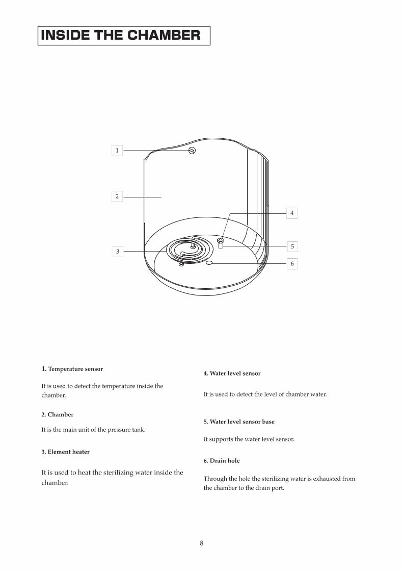
1. Temperature sensor
Itisusedtodetectthetemperatureinsidethechamber.
2. Chamber
Itisthemainunitofthepressuretank.
3. Element heater
Itisusedtoheatthesterilizingwaterinsidethechamber.
4. Water level sensor
Itisusedtodetectthelevelofchamberwater.
5. Water level sensor base
Itsupportsthewaterlevelsensor.
6. Drain hole
Throughtheholethesterilizingwaterisexhaustedfromthechambertothedrainport.
INSIDE THE CHAMBER
1
2
4
3
6
5

9
PIPING DIAGRAM
a. Safety valve
e. Pressure gauge
f. Pressure switch
b. Ball valve
g. Exhaust bottle
c. Exhaust valve
d. Air release valve
a
b
c
d
PS2 PS1
P
e
g
f
10
CONTROL PANEL
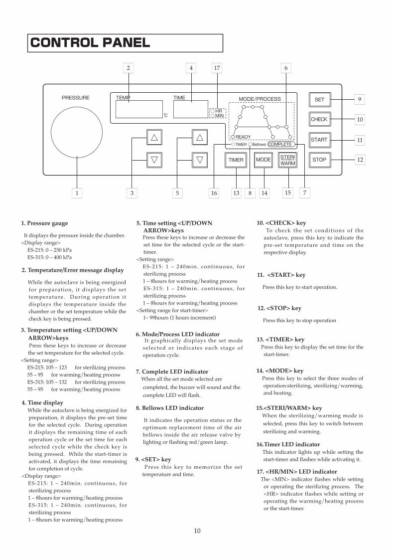
3. Temperature setting <UP/DOWN ARROW>keys
Press thesekeys to increaseordecreasethesettemperaturefortheselectedcycle.
<Settingrange> ES-215:105–123℃forsterilizingprocess 55–95℃forwarming/heatingprocess ES-315:105–132℃forsterilizingprocess 55–95℃forwarming/heatingprocess
1. Pressure gauge
Itdisplaysthepressureinsidethechamber.<Displayrange> ES-215:0–250kPa ES-315:0–400kPa
2. Temperature/Error message display
While the autoclave isbeing energizedfor preparation, it displays the settemperature. During operat ion i tdisplays the temperature inside thechamberorthesettemperaturewhilethecheckkeyisbeingpressed.
4. Time displayWhiletheautoclaveisbeingenergizedfor
preparation, itdisplays thepre-set timefor the selected cycle. During operationit displays the remaining time of eachoperation cycle or the set time for eachselected cycle while the check key isbeingpressed. While the start-timer isactivated, it displays the time remainingforcompletionofcycle.
<Displayrange> ES-215: 1 – 240min. continuous, for
sterilizingprocess 1–8hoursforwarming/heatingprocess ES-315: 1 – 240min. continuous, for
sterilizingprocess 1–8hoursforwarming/heatingprocess
9. <SET> key Press this key to memorize the set
temperatureandtime.
5. Time setting <UP/DOWN ARROW>keys
Pressthesekeystoincreaseordecreasetheset timefor theselectedcycleor thestart-timer.
<Settingrange> ES-215: 1 – 240min. continuous, for
sterilizingprocess 1–8hoursforwarming/heatingprocess ES-315: 1 – 240min. continuous, for
sterilizingprocess 1–8hoursforwarming/heatingprocess<Settingrangeforstart-timer>1–99hours(1hoursincrement)
6. Mode/Process LED indicator It graphically displays the set mode
selected or indicates each s tage ofoperationcycle.
10. <CHECK> key To check the set condit ions of the
autoclave, press thiskey to indicate thepre-set temperature and time on therespectivedisplay.
15.<STERI/WARM> key When the sterilizing/warming mode is
selected,pressthiskeytoswitchbetweensterilizingandwarming.
11. <START> key
Pressthiskeytostartoperation.
12. <STOP> key
Pressthiskeytostopoperation
7. Complete LED indicator Whenallthesetmodeselectedare
completed,thebuzzerwillsoundandthecompleteLEDwillflash.
8. Bellows LED indicator
It indicates theoperation status or theoptimum replacement time of the airbellows inside the air release valve bylightingorflashingred/greenlamp.
13. <TIMER> keyPressthiskeytodisplaythesettimeforthe
start-timer.
14. <MODE> key Press thiskeytoselect thethreemodesof
operation:sterilizing,sterilizing/warming,andheating.
16.Timer LED indicator This indicator lights up while setting the
start-timerandflasheswhileactivatingit.
17. <HR/MIN> LED indicator The<MIN> indicator flasheswhile setting
oroperating the sterilizing process. The<HR> indicator flasheswhile setting oroperating thewarming/heatingprocessorthestart-timer.
1 5 78
9
10
4
12
13 14 1516
17
3
11
2 6
MODE/PROCESS
COMPLETE
READY
Bellows
SET
CHECK
START
STOP
TEMP TIME
MIN℃
PRESSURE
STERITIMER MODEWARM
TIMER
HR
11
3. INSTALLATION3-1. RELOCATION AND INSTALLATION
WarningDo not install the instrument in a place where such chemicals as flammable or corrosive gases are stored.•Doingsocancausefireorshortcircuitandelectricshockduetothecorrosionofelectricalparts.
Do not install the instrument in a dusty or wet place•Doingsocancauseshortcircuitorignitionofelectricalparts.
Do not install the instrument near a sink, a water pipe or in a place where there is a risk of it being splashed with water.•Doingsocancauseshortcircuitorelectricshock.
Install the instrument on a firm and level surface such as a concrete floor.
•Failuretodosomayresultininjurytopersonnelorphysicaldamagetopropertyduetoupsettingoftheinstrument.
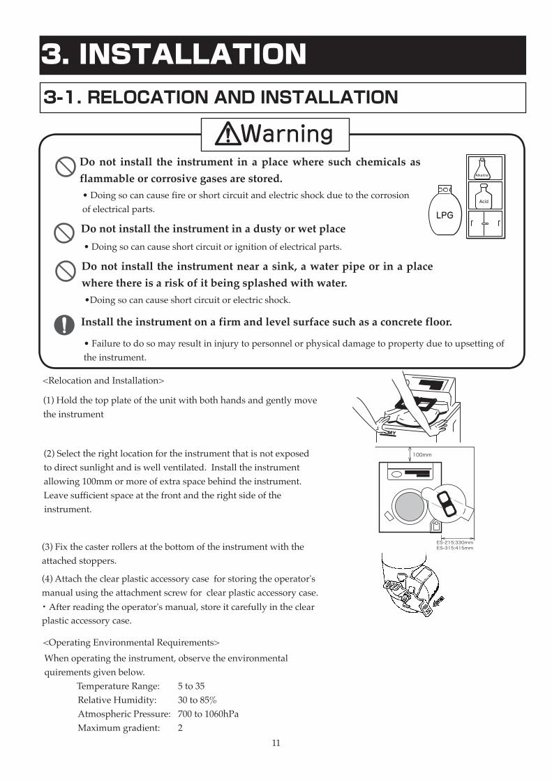
(1)Holdthetopplateoftheunitwithbothhandsandgentlymovetheinstrument
(2)Selecttherightlocationfortheinstrumentthatisnotexposedtodirectsunlightandiswellventilated.Installtheinstrumentallowing100mmormoreofextraspacebehindtheinstrument.Leavesufficientspaceatthefrontandtherightsideoftheinstrument.
(3)Fixthecasterrollersatthebottomoftheinstrumentwiththeattachedstoppers.
Whenoperatingtheinstrument,observetheenvironmentalquirementsgivenbelow.TemperatureRange: 5to35℃
RelativeHumidity: 30to85% AtmosphericPressure: 700to1060hPa Maximumgradient: 2°
<RelocationandInstallation>
<OperatingEnvironmentalRequirements>
TOMY
ES-215:330mmES-315:415mm
100mm
(4)Attachtheclearplasticaccessorycaseforstoringtheoperator'smanualusingtheattachmentscrewforclearplasticaccessorycase.・Afterreadingtheoperator'smanual,storeitcarefullyintheclearplasticaccessorycase.

12
3-2. POWER SUPPLY CONNECTION AND PROPER GROUNDING (EARTHING)
WarningPlug the power cord singly into an electric outlet with the specified voltage.•Failuretodosocancausefire,shortcircuitormalfunctionduetoignition.
Do not use power cable extensions.•Doingsocancausefire,shortcircuitormalfunctionduetoignition.
Be sure to provide protective grounding for the instrument.•Failuretodosomayresultinexplosion,electricshockormalfunction.
Do not use a gas pipe or water pipes for protective grounding.•Doingsocancauseexplosion,electricshockormalfunction.
Groundingelectricalequipmentisrequiredtoprotectagainstelectricshock.Whengroundingcannotbeprovided,requestspecialistsforanadequategroundingfortheinstrument
Justplugtheprovidedpowercorddirectlyandsinglyintotheoutlettomeettheconditionsgivenbelow:
Powersupplyconditions:ES-215;single-phase120VAC(50/60Hz),15Aormore single-phase220VAC(50/60Hz),15Aormoresingle-phase230VAC(50/60Hz),15Aormore single-phase240VAC(50/60Hz),15AormoreES-315;single-phase120VAC(50/60Hz),20Aormore single-phase220VAC(50/60Hz),15Aormoresingle-phase230VAC(50/60Hz),15Aormore single-phase240VAC(50/60Hz),15Aormore
*Theelectricalvoltageofthepoweroutletshouldbeconsistentwiththeratedvoltageoftheinstrument.Theratedvoltageoftheinstrumentisshownontheproductnameplatelabel.
Protectionagainstelectricalshockisprovidedbyconnectingwireontheplugforgroundingtothegroundingterminal.
*Ifitbeginstothunder,pullthepowerplugoutofthepoweroutlettoavoidhavingdamagefromthelightning.

13
1. Turning on the power switch P.142. Checking the pressure gauge P.163. Checking the exhaust bottle P.164. Checking the sterilizing water P.175. Placing the material to be sterilized P.186. Selecting the operation mode P.207. Setting the operation conditions P.218. Starting the operation P.229. Completing the operation P.2310. Removing the sterilized material P.2311. Draining the sterilizing water P.2412. Turning off the power switch P.14
*When operating the instrument in a constant run mode, check the pressure gauge before restarting operation after removing the sterilized material from the chamber.
4. FLOW OF OPERATION

14
5. HOW TO OPERATE
5-1.TURNING ON/OFF THE POWER SUPPLY SWITCH
Do not touch the power supply switch with wet hands.•Doingsocancauseelectricshocktotheuser.
<Turning ON the power supply switch>(1) Before turning on the instrument, make sure that the power supply is properly connected and the protective grounding is provided.(2) Turn on the power switch located on the right side of the main unit. The control panel will light and display preset values of each parameter and the LED indicators will flash and show the instrument is ready for operation.
<Turning OFF the power supply switch>(1) Turn off the power switch on the right side of the main unit.
15
5-2. OPENING/CLOSING THE CHAMBER LID
Never open the chamber lid until the chamber temperature falls to 97℃ or less at the pressure of 0kPa.•Openingthechamberlidwhileinflationarypressureremainsinsidecancausedeathorseriousaccidentduetoblowoutofthesterilizedmaterialorthesteamfromthechamber..
Use caution when opening the chamber lid, as the steam from the chamber is hot.•Failuretodosocancauseburnsorinjury
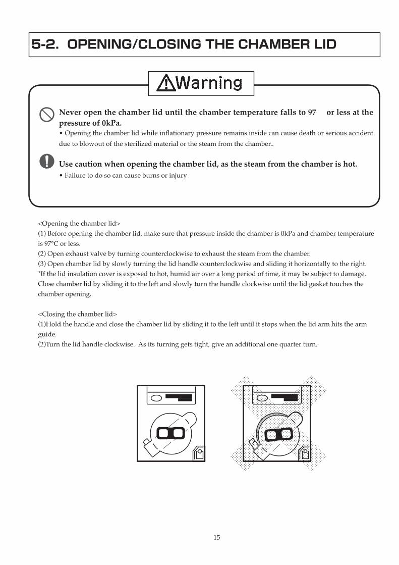
<Openingthechamberlid>(1)Beforeopeningthechamberlid,makesurethatpressureinsidethechamberis0kPaandchambertemperatureis97℃orless.(2)Openexhaustvalvebyturningcounterclockwisetoexhaustthesteamfromthechamber.(3)Openchamberlidbyslowlyturningthelidhandlecounterclockwiseandslidingithorizontallytotheright.*Ifthelidinsulationcoverisexposedtohot,humidairoveralongperiodoftime,itmaybesubjecttodamage.Closechamberlidbyslidingittotheleftandslowlyturnthehandleclockwiseuntilthelidgaskettouchesthechamberopening.
<Closingthechamberlid>(1)Holdthehandleandclosethechamberlidbyslidingittotheleftuntilitstopswhenthelidarmhitsthearmguide.(2)Turnthelidhandleclockwise.Asitsturninggetstight,giveanadditionalonequarterturn.
16
Stop operating the instrument when the pressure gauge is not working normally•If the operating conditions inside chamber cannot be monitoredcorrectlywith thepressure gauge, it can causehazardous situations.ContactyourdealerorthenearestTOMYofficeforrepairs
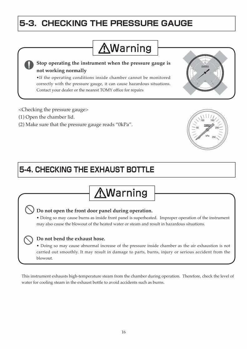
5-3. CHECKING THE PRESSURE GAUGE
<Checkingthepressuregauge>(1)Openthechamberlid.(2)Makesurethatthepressuregaugereads“0kPa”.
0 250
50
100 150
200
kPa
5-4. CHECKING THE EXHAUST BOTTLE
Do not open the front door panel during operation.•Doingsomaycauseburnsasinsidefrontpanelissuperheated.Improperoperationoftheinstrumentmayalsocausetheblowoutoftheheatedwaterorsteamandresultinhazardoussituations.
Thisinstrumentexhaustshigh-temperaturesteamfromthechamberduringoperation.Therefore,checkthelevelofwaterforcoolingsteamintheexhaustbottletoavoidaccidentssuchasburns.
Do not bend the exhaust hose.•Doing somay cause abnormal increase of thepressure inside chamber as theair exhaustion is notcarried out smoothly. Itmay result indamage toparts, burns, injury or serious accident from theblowout.

17
<Checkingtheexhaustbottle>(1)Makesurethatthelevelofwaterintheexhaustbottleisbetweenthemarksofthelowestandhighestlevel.Fillwaterifneededaccordingtothefollowingprocedure:(2)Turntheunitoffatthemainswitchafterconfirmingthatthetemperatureinsidechamberiscoolenough.(3)Openthefrontdoorpanelandremovetheexhaustbottleslowlyfromthemainunit.(4)Holdthejointoftheexhausthoseandslowlypullitoutfromtheexhaustbottle.(5)Removethecaponthetopofthebottleandfillwaterfromthefill/drainporttotheminimumlevel.(6)Pushthecaponthefill/drainportandpushtheendoftheexhausthoseintothebackofthebottle.(7)Mountthebottleslowlyonthestorageshelfofthemainunit.(8)Closethefrontdoorpanel.
5-5. CHECKING THE STERILIZING WATERThisinstrumentgeneratessteambyheatingthesterilizingwaterinsidechamber.Checkthequalityandthelevelofthechamberwaterforpropersterilization.
<Checkingthesterilizingwater>(1)Openthechamberlidandmakesurethechamberwaterisnotcontaminated.(2)Whenthechamberwateriscontaminated,drainit.*See5-12.DRAININGTHESTERILIZINGWATERforfurtherreference.(3)Checkthelevelofwaterreachesthebottomplateofthechamberbasket(stainlesssteelwiremeshbasket).*Whensterilizingwithalargevolumeofliquidinthebucket,filltapwateruntilthebottomofthebucketissoakedinwaterapproximately5cmabovethebottomofthebucket.(4)Addtapwaterifneeded,untilthewaterlevelreachesthebottomplateofthechamberbasket.
<Guideforthelevelofthesterilizingwater> ES-215: approximately1.5L ES-315: approximately3.0L
5㎝
Cap
Joint of the exhaust hose
By-pass hole
Exhaust hose
Main body
Fill/drain port
Exhaust bottle
Mark of the highest level
Mark of the lowest level

1818
5-6. PLACING THE MATERIAL TO BE STERILIZED
Do not put inflammable or explosive substance inside the instrument. •Doingsocancausefireorexplosion.
Do not sterilize sealed materials.•Doing somay result inanexplosionof super-heatedmaterialwhen it isremoved from the chamber andcause burns or serious accident. Itmayalsoresult in the abnormal increase of pressure inside chamber and can causedamagetoparts,burnsorseriousaccidentduetoexplosivebreakage.
Do not sterilize glass equipments having cracks or scratches.•Doing somay result inanexplosion ofglass equipment when it is removedfromthechamberandcauseburnsorseriousaccident.
Do not operate the instrument without storing the material to be sterilized in the chamber basket (stainless steel wire mesh basket). • If the basket isnot used, it may cause anexplosion of the chamber as theexhaustholeisblockedbysuchmaterialsasasterilizingbagandthepressureinsidethechambercannotbecontrolled.
Make sure the chamber lid is securely closed before starting operation. •Failure todo somaycause burnsas theunexpectedhot steam is escapingthroughspacebetweenthelidandthechamberunit.
<Placingthematerialtobesterilized>(1)Placematerialstobesterilizedintheprovidedstainlessbasketorinanoptionalstainlessbucket.(2)Placethematerialslowlyinthechamber.(3)Closethechamberlid.(4)Closetheexhaustvalvesecurelybyturningtheexhaustvalveknobclockwiseuntiltight.
1919
Adaptation Polyethylene Polypropylene co
polymer
Polypropylene Polycarbonate Tefron FEP
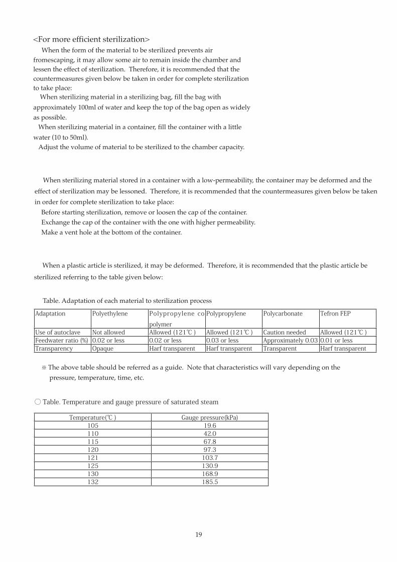
Use of autoclave Not allowed Allowed (121℃ ) Allowed (121℃ ) Caution needed Allowed (121℃ )Feedwater ratio (%) 0.02 or less 0.02 or less 0.03 or less Approximately 0.03 0.01 or lessTransparency Opaque Harf transparent Harf transparent Transparent Harf transparent
Table.Adaptationofeachmaterialtosterilizationprocess
※ Theabovetableshouldbereferredasaguide.Notethatcharacteristicswillvarydependingonthe pressure,temperature,time,etc.
<Formoreefficientsterilization>○Whentheformofthematerialtobesterilizedpreventsairfromescaping,itmayallowsomeairtoremaininsidethechamberandlessentheeffectofsterilization.Therefore,itisrecommendedthatthecountermeasuresgivenbelowbetakeninorderforcompletesterilizationtotakeplace:・Whensterilizingmaterialinasterilizingbag,fillthebagwithapproximately100mlofwaterandkeepthetopofthebagopenaswidelyaspossible.・Whensterilizingmaterialinacontainer,fillthecontainerwithalittlewater(10to50ml).・Adjustthevolumeofmaterialtobesterilizedtothechambercapacity.
○Whensterilizingmaterialstoredinacontainerwithalow-permeability,thecontainermaybedeformedandtheeffectofsterilizationmaybelessoned.Therefore,itisrecommendedthatthecountermeasuresgivenbelowbetakeninorderforcompletesterilizationtotakeplace:・Beforestartingsterilization,removeorloosenthecapofthecontainer.・Exchangethecapofthecontainerwiththeonewithhigherpermeability.・Makeaventholeatthebottomofthecontainer.
○Whenaplasticarticleissterilized,itmaybedeformed.Therefore,itisrecommendedthattheplasticarticlebe
sterilizedreferringtothetablegivenbelow:
Temperature(℃ ) Gauge pressure(kPa)105 19.6110 42.0115 67.8120 97.3121 103.7125 130.9130 168.9132 185.5
○ Table. Temperature and gauge pressure of saturated steam

2020
5-7. SELECTING THE OPERATING MODE
Inthesterilizingmode,itprovidesastandardsterilizingoperation.Inthesterilizing-warmingmode,itprovidesasterilizingoperationandwarmingoperationaftersterilizingcycleiscompleted.Intheheatingmode,itprovidesaheatingoperationunder95℃.BypressingtheMODEkey,thethreeoperatingmodes;sterilizing,sterilizing-warming,andheatingmodewillappearinorder.SelectthedesiredmodebypressingtheMODEkey.Whenthemodeischanged,theMODE/PROCESSdisplaylampwilllighttoindicatetheselectedmodeandtheinstrumentwillbeeptwotimes.Whenturningonthepower,thesterilizingmodeisselected.
STERILIZINGMODE
Itprovidesasterilizingoperation.Itallowssettingofthetemperatureandtimeforthesterilizingprocess.
STERILIZING-WARMINGMODE
Itprovidesasterilizingoperationandawarmingoperationaftersterilizingprocessiscompleted.Itallowssettingoftemperatureandtimeforboththesterilizingandwarmingprocesses.
HEATINGMODE
Itprovidesaheatingoperationunder95℃.Itallowssettingofthetemperatureandtimefortheheatingprocess.
<Selectingthesterilizingmode>
(1)PresstheMODEkeytoselectthesterilizingmode.
MODE/PROCESS
COMPLETE
READY
Bellows
SET
CHECK
START
STOP
TEMP TIME
MIN℃
STERITIMER MODEWARM
TIMER
HR
MODE/PROCESS
COMPLETE
READY
Bellows
SET
CHECK
START
STOP
TEMP TIME
MIN℃
STERITIMER MODEWARM
TIMER
HR
MODE/PROCESS
COMPLETE
READY
Bellows
SET
CHECK
START
STOP
TEMP TIME
MIN℃
STERITIMER MODEWARM
TIMER
HR
2121
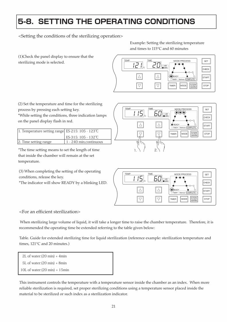
5-8. SETTING THE OPERATING CONDITIONS
<Settingtheconditionsofthesterilizingoperation>
(1)Checkthepaneldisplaytoensurethatthesterilizingmodeisselected.
(2)Setthetemperatureandtimeforthesterilizingprocessbypressingeachsettingkey.*Whilesettingtheconditions,threeindicationlampsonthepaneldisplayflashinred.
1. Temperature setting range ES-215: 105 - 123℃
ES-315: 105 - 132℃2. Time setting range 1 - 240 min,continuous
*Thetimesettingmeanstosetthelengthoftimethatinsidethechamberwillremainatthesettemperature.
(3)Whencompletingthesettingoftheoperatingconditions,releasethekey.*TheindicatorwillshowREADYbyablinkingLED.
<Foranefficientsterilization>
Whensterilizinglargevolumeofliquid,itwilltakealongertimetoraisethechambertemperature.Therefore,itisrecommendedtheoperatingtimebeextendedreferringtothetablegivenbelow:
Table.Guideforextendedsterilizingtimeforliquidsterilization(referenceexample:sterilizationtemperatureandtimes,121°Cand20minutes.)
2L of water:(20 min) + 4min
5L of water:(20 min) + 8min
10L of water:(20 min) + 15min
Thisinstrumentcontrolsthetemperaturewithatemperaturesensorinsidethechamberasanindex.Whenmorereliablesterilizationisrequired,setpropersterilizingconditionsusingatemperaturesensorplacedinsidethematerialtobesterilizedorsuchindexasasterilizationindicator.
MODE/PROCESS
COMPLETE
READY
Bellows
SET
CHECK
START
STOP
TEMP TIME
MIN℃
STERITIMER MODEWARM
TIMER
HR
MODE/PROCESS
COMPLETE
READY
Bellows
SET
CHECK
START
STOP
TEMP TIME
MIN℃
STERITIMER MODEWARM
TIMER
HR
1. 2.
MODE/PROCESS
COMPLETE
READY
Bellows
SET
CHECK
START
STOP
TEMP TIME
MIN℃
STERITIMER MODEWARM
TIMER
HR
Example:Settingthesterilizingtemperatureandtimesto115°Cand60minutes

2222
5-9. STARTING THE OPERATION
Do not open the front door panel during operation.
• Doingsocancauseburnstotheuserasinsidethefrontpanelwillbecomeveryhotduringoperation.Itmayalsoresultinablowoutofhotwaterandsteamduetothemishandlingoftheinstrument.
Stop running the instrument immediately when the pressure enters the red zone on the indicator gauge during operation.
•Failuretodosocancausedamagetotheparts,burnsorseriousaccidentduetothebreakageoftheparts.TurnofftheinstrumentimmediatelyandcontactyourdealerorthenearestTOMYoffice.
When operating the instrument in a constant run mode, take more than 10 minutes interval between running after the chamber temperature drops to 60℃ or below.
•Failuretodosomayresultinanexplosionthatcancauseburnsorinjuryordamagetotheinstrumentpartsasthepressureinsidethechamberrisesabnormallyhigh.
Be careful of superheated steam coming from the steam exhaust hole during operation.
•Failuretodosocancauseburnstotheuser.
(1)PresstheSTARTkey.TheMODE/PROCESSdisplayLEDwilllightandindicateeachstageofthesterilizingcycleasthechambertemperaturerisesandthesterilizationtimehaspassed.*WhenpressingtheSTARTkeyrightafterturningonthepowerswitch,anerrormessagemayappearonthedisplay.Afterturningonthepower,waitforatleast10secondsbeforepressingtheSTARTkey.*Duringoperationthetemperatureandthetimedisplaywillindicatethechambertemperatureandthetimeremainingrespectively.*WhentheCHECKkeyispressedduringoperation,thedisplaywillswitchtothesettemperatureandtimeandkeepindicatingthesetvaluesbyholdingdownthekey.*Ifablackoutoccursduringoperation,theinstrumentwillstoptheoperationandreturntotheinitialsettingmode(thesterilizingmode)whenthepoweristurnedon.Restarttheselectionofoperatingmode.

23 23
5-10. COMPLETING THE OPERATION
5-11. REMOVING THE STERILIZED MATERIAL
Never open the chamber lid unless the pressure has returned to 0 kPa and the temperature is bellow 97℃ .•Openingthelidwhileinflationarypressureremainsinthechambercancausedeathorseriousaccidentduetotheblowoutofsterilizedarticlesorsteam.
Use caution when opening the chamber lid.
•Failuretodosomaycauseburnsorinjurybecausethesteamemanatingfrominsidechamberhasanextremelyhightemperature.
Use extreme caution when handling autoclaved liquids since they are hot and may suddenly boil over.
•Thetemperatureofautoclavedliquidsfallsmoreslowlythanthetemperatureinsidechamber.Superheatedliquidsmaysuddenlyboilwhenmovedortouched.Aneruptionmayresultinburnsorseriousaccident.
Immediatelyorshortlyaftercompletionoftheoperation,asuddenandexplosiveboilingmayoccurandcancauseburnstotheuser.Therefore,itisrecommendedthatthechamberlidbeopenedafterthecoolingprocessisoverandthewholesterilizingcycleiscompleted
<Completingtheoperation>
(1)Whenthesetsterilizationtimehaselapsedandthesterilizingcycleiscompleted,theinstrumentwillbeep3times.(2)Whenthechambertemperaturefallsto97℃andthesterilizingoperationiscompleted,theinstrumentwillbeep6times.(3)Whenthechambertemperaturefallsto60℃andthecoolingcycleiscompleted,theinstrumentwillbeep10timesandthewholesterilizingcyclewillbecompleted.*OperationcanbeinterruptedbypressingtheSTOPkey.*Whenoperationisinterrupted,theoperatingcyclewillshifttothecoolingcycle.
Do not leave inside the chamber or sterilizing water contaminated.
•Doingsocancausecorrosionordamagetothechamber.Itmayalsocausemalfunctionofthewaterlevelsensortopreventthechamberfromheatingwithnoorlowwaterinsideandfirecanbeoccurredbyblankheating

2424
5-12. DRAINING THE STERILIZING WATER
(1)Makesurethatthechamberpressurehasreturnedto0kPaandthetemperatureisbellow97℃beforeopeningthechamberlid.Immediatelyorshortlyaftercompletionoftheoperation,suddenboilingeruptionsmayoccurandcauseburnstotheuser.Therefore,itisrecommendedthatthechamberlidbeopenedafterthecoolingprocessisoverandthewholesterilizingcycleiscompleted.(2)Openthechamberlid.(3)Removethesterilizedmaterialfromthechamber.*Ifinsidethechamberorthechamberwateriscontaminated,cleanitbyreferringto7.MAINTENANCEANDADJUSTMENT.(4)Wheninsidethechamberisstillhot,closethechamberlidbyslidingittotheleftandslowlyturnthehandleclockwiseuntilthelidgaskettouchesthechamberopening.
<Removingthesterilizedmaterial>
Do not drain until the sterilizing water cools down sufficiently.
•Doingsocancauseburnsasthesterilizingwaterisveryhotrightafterrunning.
(1)Openthechamberlid.(2)Slowlyremovethebasket(astainlesssteelbasketwithslattedbottomplate)fromthechamber.(3)Makesurethatthesterilizingwaterissufficientlycooleddown.(4)Openthefrontpaneldoor.(5)Placethedraincontainerbelowthedrainport.(6)Openthedraincockbyturningitslowlyanddrainthesterilizingwaterfromthedrainport.Whenthesterilizingwaterisnotdrainedduetoclogs,clearthembyinsertingawireetc.throughthedrainport.(7)Afterdrainingoffthesterilizingwater,turncockfullytoclosethedrainport.(8)Closethefrontdoorpanel(9)Slowlyplacethebasketintothechamber.
<Draining the sterilizing water>
Drain cock
Drain port

2525
6. CONVENIENT FUNCTIONS
6-1. STERILIZING-WARMING MODE
<Operatingsterilizing-warmingfunction>
(1)Whensettingtheoperatingconditions,presstheMODEkeytoselecttheSTERILIZING-WARMINGMODE.
Example:Paneldisplayofthesterilizing-warmingmode(sterilizationtemperatureandtimes,115°Cand60minutes,warmingtemperatureandtimes,55°Cand2hours)
(2)Setthetemperatureandtimeforthesterilizingprocessbypressingeachsettingkey.
1. Temperature settinng
range
ES-215: 105 - 123℃
ES-315: 105 - 132℃2. Time setting range 1 - 240 min,or continuously
*Whilesettingtheconditions,threeindicationlampsonthepaneldisplayflashinred.*Thesettimemeanstheretentiontimeforthesetchambertemperature.
(3)Aftersettingthesterilizationtemperatureandtime,themodewillchangetothewarmingsettinginthreeminutes.Setthetemperatureandtimeforthewarmingprocessbypressingeachsettingkey.*ThemodecanalsobechangedtothewarmingsettingbypressingtheSTERI/WARMkeyoncewithoutwaitingforthreeseconds.
3. Temperature setting
range
55 - 95℃
4. Time setting range 1 - 8 hours
*Whilesettingtheconditions,threeindicationlampsonthepaneldisplayflashinred.
MODE/PROCESS
COMPLETE
READY
Bellows
SET
CHECK
START
STOP
TEMP TIME
MIN℃
STERITIMER MODEWARM
TIMER
HR
MODE/PROCESS
COMPLETE
READY
Bellows
SET
CHECK
START
STOP
TEMP TIME
MIN℃
STERITIMER MODEWARM
TIMER
HR
1. 2.
MODE/PROCESS
COMPLETE
READY
Bellows
SET
CHECK
START
STOP
TEMP TIME
MIN℃
STERITIMER MODEWARM
TIMER
HR
MODE/PROCESS
COMPLETE
READY
Bellows
SET
CHECK
START
STOP
TEMP TIME
MIN℃
STERITIMER MODEWARM
TIMER
HR
3. 4.

2626
(4)Whenthesettingoftheoperatingconditionsiscompleted,releasethesettingkey.*TheindicatorwillshowREADYbyablinkingLEDinthreesecondsafterreleasingthekey.
(5)PresstheSTARTkey.
<Completingthesterilizing-warmingfunction>
(1)Whenthesetsterilizingtimeisoverandthesterilizingcycleiscompleted,theinstrumentwillbeep3times.*Whenturningtheexhaustvalveknobaftercompletingthesterilizingprocess,anerrormessagewillappearonthedisplayandtheoperationwillstop.(2)Whenthechambertemperaturefallsto97℃andthesterilizingoperationiscompleted,theinstrumentwillbeep6times.(3)Whenthechambertemperaturefallstothesetwarmingtemperature,thewarmingcyclewillstart.(4)Whenthewarmingtimeisoverandthewarmingcycleiscompleted,theinstrumentwillbeep3times.(5)Whenthechambertemperaturefallsto60℃andthecoolingcycleisover,theinstrumentwillbeep10timesandthewholeoperatingcyclewillbecompleted. *Whenthewarmingtemperatureissetto60℃orbelow,thebuzzerwillsoundsuccessively3timesand10timesaftercompletingwarmingcycleandthewholeoperatingcyclewillbecompleted.*OperationcanbeinterruptedbypressingtheSTOPkey.*Whenoperationisinterrupted,theoperatingcyclewillshifttothecoolingcycle.
MODE/PROCESS
COMPLETE
READY
Bellows
SET
CHECK
START
STOP
TEMP TIME
MIN℃
STERITIMER MODEWARM
TIMER
HR

2727
6-2. HEATING MODE
<Operatingtheheatingfunction>
(1)Whensettingtheoperatingconditions,presstheMODEkeytoselecttheheatingmode.
Example:Paneldisplayoftheheatingmode(heatingtemperatureandtimes,85°Cand1hour)
(2)Setthetemperatureandtimefortheheatingprocessbypressingeachsettingkey.
1. Temperature setting
range
55 - 95℃
2. Time setting range 1 - 8 hours
*Whilesettingtheconditions,fourindicationlampsonthepaneldisplayflashinred.*Thesettimemeanstotheretentiontimeforthesetchambertemperature.
(3)Whenthesettingoftheoperatingconditionsiscompleted,releasethesettingkey.*TheindicatorwillshowREADYbyablinkingLEDinthreesecondsafterreleasingthekey.
(4)PresstheSTARTkey.
<Completingtheheatingfunction>
(1)Whenthesetheatingtimeisoverandtheheatingcycleiscompleted,theinstrumentwillbeep3times.(2)Whenthechambertemperaturefallsto60℃andthecoolingcycleisover,theinstrumentwillbeep10timesandthewholeoperatingcyclewillbecompleted.*OperationcanbeinterruptedbypressingtheSTOPkey.*Whenoperationisinterrupted,theoperatingcyclewillshifttothecoolingcycle.
MODE/PROCESS
COMPLETE
READY
Bellows
SET
CHECK
START
STOP
TEMP TIME
MIN℃
STERITIMER MODEWARM
TIMER
HR
MODE/PROCESS
COMPLETE
READY
Bellows
SET
CHECK
START
STOP
TEMP TIME
MIN℃
STERITIMER MODEWARM
TIMER
HR
1.
2.
MODE/PROCESS
COMPLETE
READY
Bellows
SET
CHECK
START
STOP
TEMP TIME
MIN℃
STERITIMER MODEWARM
TIMER
HR
28
MODE/PROCESS
COMPLETE
READY
Bellows
SET
CHECK
START
STOP
TEMP TIME
MIN℃
STERITIMER MODEWARM
TIMER
HR
28
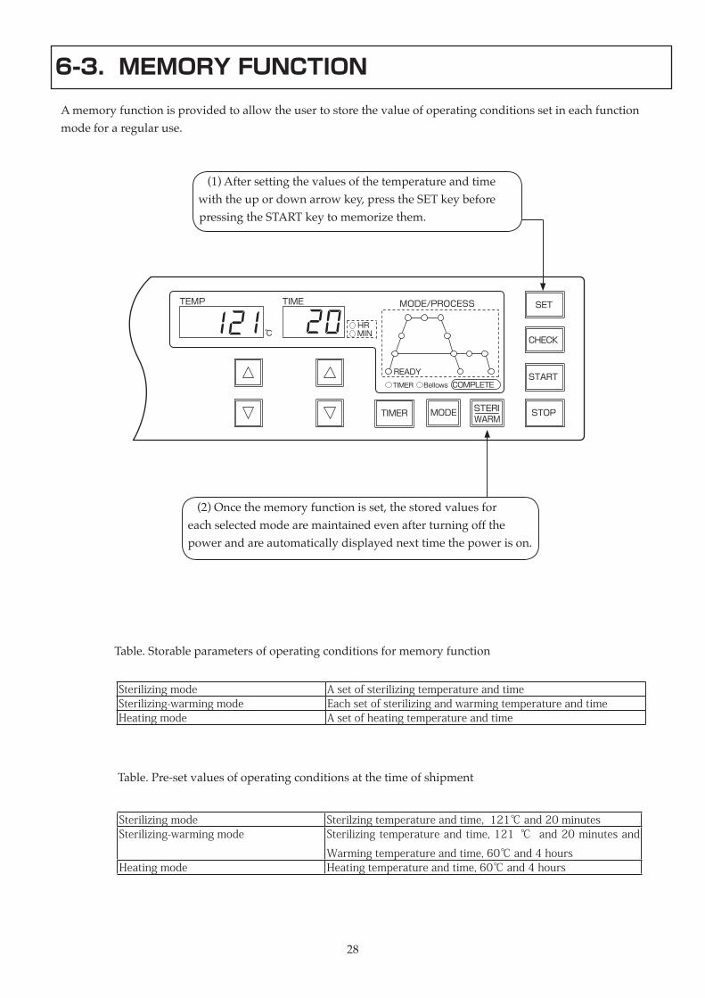
6-3. MEMORY FUNCTION
Amemoryfunctionisprovidedtoallowtheusertostorethevalueofoperatingconditionssetineachfunctionmodeforaregularuse.
(1)Aftersettingthevaluesofthetemperatureandtimewiththeupordownarrowkey,presstheSETkeybeforepressingtheSTARTkeytomemorizethem.
(2)Oncethememoryfunctionisset,thestoredvaluesforeachselectedmodearemaintainedevenafterturningoffthepowerandareautomaticallydisplayednexttimethepowerison.
Table.Storableparametersofoperatingconditionsformemoryfunction
Sterilizing mode A set of sterilizing temperature and timeSterilizing-warming mode Each set of sterilizing and warming temperature and timeHeating mode A set of heating temperature and time
Table.Pre-setvaluesofoperatingconditionsatthetimeofshipment
Sterilizing mode Sterilzing temperature and time, 121℃ and 20 minutesSterilizing-warming mode Sterilizing temperature and time, 121 ℃ and 20 minutes and
Warming temperature and time, 60℃ and 4 hoursHeating mode Heating temperature and time, 60℃ and 4 hours
29
MODE/PROCESS
COMPLETE
READY
Bellows
SET
CHECK
START
STOP
TEMP TIME
MIN℃
STERITIMER MODEWARM
TIMER
HR
29
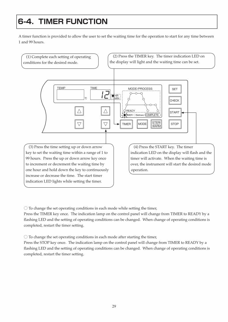
6-4. TIMER FUNCTION
Atimerfunctionisprovidedtoallowtheusertosetthewaitingtimefortheoperationtostartforanytimebetween1and99hours.
(1)Completeeachsettingofoperatingconditionsforthedesiredmode.
(2)PresstheTIMERkey.ThetimerindicationLEDonthedisplaywilllightandthewaitingtimecanbeset.
(3)Pressthetimesettingupordownarrowkeytosetthewaitingtimewithinarangeof1to99hours.Presstheupordownarrowkeyoncetoincrementordecrementthewaitingtimebyonehourandholddownthekeytocontinuouslyincreaseordecreasethetime.ThestarttimerindicationLEDlightswhilesettingthetimer.
(4)PresstheSTARTkey.ThetimerindicationLEDonthedisplaywillflashandthetimerwillactivate.Whenthewaitingtimeisover,theinstrumentwillstartthedesiredmodeoperation.
○ Tochangethesetoperatingconditionsineachmodewhilesettingthetimer,PresstheTIMERkeyonce.TheindicationlamponthecontrolpanelwillchangefromTIMERtoREADYbyaflashingLEDandthesettingofoperatingconditionscanbechanged.Whenchangeofoperatingconditionsiscompleted,restartthetimersetting.
○ Tochangethesetoperatingconditionsineachmodeafterstartingthetimer,PresstheSTOPkeyonce.TheindicationlamponthecontrolpanelwillchangefromTIMERtoREADYbyaflashingLEDandthesettingofoperatingconditionscanbechanged.Whenchangeofoperatingconditionsiscompleted,restartthetimersetting.
3030
Warning
When executing maintenance sequences, be sure to unplug the instrument first to avoid electric shock.•Formodelswithnopowerplug,turnoffthebreakertowhichthepowercordisconnected.
7. MAINTENANCE AND ADJUSTMENT
When executing maintenance sequences, make sure that the temperature inside the chamber falls down sufficiently.•Failuretodosocancauseburnstotheuser.
7-1. CLEANING AND DISINFECTING THE MAIN UNIT
Whentheouterpanelortheinsidethechamberiscontaminated,performcleaninganddisinfectinginaccordancewiththefollowingmethod:
<Cleaningthemainunit>
(1)Wipeexteriororinterioroftheunitwithasoftclothdampenedinmilddetergent.(2)Thoroughlywipeoffalltracesofthedetergentwithatightlysqueezeddampcloth.
<Disinfectingthemainunit>
(1)Disinfecttheunitusingethanol.

31 31
7-2. REPLACING BELLOWS
WhentheBellowsindicationlamplightsorflashesinredorgreen,replacebellowsofairreleasevalve.*TheBellowsindicationlampmayalsolightorflash,whenthevolumeofmaterialtobesterilizedistoomuchascomparedtothesizeofthechamber.Checkthevolumeofsterilizingmaterial.
Status of bellows indication lamp Operating status CountermeasuresThe green lamp flashes. The pressure does not rise. Replace bellows after the operation is completed.The green lamp lights up. The pressure does not rise. Replace bellows after stopping the operation.The red lamp flashes. The pressure rises too high. Replace bellows after the operation is completed.The red lamp lights up. The pressure rises too high. Replace bellows after stopping the operation.
(1)Turnthebellowsseatoftheairreleasevalveinthedirectionindicatedbyarrow.(Seetheabovefigure.)
(2)Removethebellowsseatfromthevalve.
(3)Turnthebellowsinthedirectionindicatedbyarrowandremoveitfromtheseat.(Seetheabovefigure.)Whendismountingthebellows,becarefulnottolosethewavewasherbetweenthebellowsandtheseat.
(4)Mountthenewbellowsthroughthewavewasherandintotheseat.Beforemounting,makesurenoforeignmatterisattachedtothegasketortheO-ringornocrackisfoundontheirsurfaces.
(5)Turnthebellowsseatinthedirectionindicatedbyarrowtomountitintotheairreleasevalve.(Asshownintherightfigure.)Closethefrontdoorpanel.
<Replacing the bellows>

3232
7-3. WEEKLY MAINTENANCE
WarningStop running the instrument if corrosion, damage or deformation is found in the chamber, chamber lid, lid arm or lid arm guide. •Failuretodosocancausedeath,injuryorseriousaccidentduetotheexplosionofthechamberwhilepressure is rising. Ifanyabnormality is found in thechamberunit,contactyourdealeror thenearestTOMYoffice.
Stop running the instrument if such damage as cracks or leaks is found on the chamber lid gasket.•Failuretodosocancauseburnstotheuserasthehotsteamescapesthroughthecrack.ContactyourdealerorthenearestTOMYofficeforaninspection.
Do not unnecessarily pull the lid gasket out of the chamber lid or deform it.•Doingsocancauseburnstotheuserduetothehotsteamescapingthroughthelid.
Forensuringsafeoperationoftheinstrument,performcleaningandinspectionaccordingtothefollowingprocedureasoftenasonceaweek.
<Cleaning>
1.Cleaningtheinsidethechamberandthewaterlevelsensor(1)Removethestainlesssteelbasketwithslattedbottomplatecarefullyoutofthechamber.(2)Thoroughlycleantheinsidethechamberandthewaterlevelsensorwithmilddetergentandclothorothersuitablematerial.Washoutthedetergentwithtapwateranddrainthewater.※ Becarefulnottodistortthesensorsinsidethechamberduringcleaning.
(3)Turnthewaterlevelsensorcounterclockwisewithhandsandremoveitfromthesensorbase.Whenremovingthesensor,becarefulnottodropitintothechamber.(4)Polishthewaterlevelsensorusinghouseholdcleanserandatoothbrushorclothuntilthesilverplatesurfaceappears.Ifthesensorisbadlycontaminated,polishittocleanwithfinesandpaper(grit#400to#800)orafile.(5)Aftercleaningthewaterlevelsensor,turnitclockwisewithhandsandmountitintothesensorbaseandsecureit.Whenmountingordismountingthewaterlevelsensor,besuretoturnitmanuallyanddonotusepliersoranyothertools
Water level sensor base
Water level sensor
remove
mount
3333
2.Cleaningthechamberlidgasket(1)Wipesurfaceofthechamberlidgasketthoroughlywithacleansoftclothwithapplyingforce.(2)Wipeopeningofthechamberwithacleansoftcloth.
3.Cleaningtheouterpanel(1)Wipeouterpanelwithasoftclothdampenedinmilddetergentandthenthoroughlywipeoffalltracesofthedetergentwithadampcloth.
<Inspection>
1.Checkingtheleakagebreaker(1)Turnonpoweratthemainswitch.(2)Presstheredtestbuttonlocatedinsidethepowerswitchwithaslimrod.(3)Whentheswitchisautomaticallyturnedoff,theleakagebreakerworksnormally.Ifnot,contactyourdealerorthenearestTOMYoffice.
2.Checkingthepressuretank(1)Checkthepressuretankforanydamageorcracks.(2)Checktheinsidethechamberforanycorrosionordamagesuchascracks.(3)Checkthechamberlidforanycorrosionordamagesuchascracks.(4)Checkthelidarmandlidarmguideforanycorrosionordamagesuchascracks.

3434
8. TROUBLESHOOTING
8-1. PROBLEMS AND COUNTERMEASURES
Whentheinstrumentdoesnotoperatenormallyeventhoughoperationisperformedcorrectlyaccordingtothisoperator'smanual,taketheappropriateactionreferringto“Problemsandcountermeasures”statedbelow.Iftheproblemcannotbesolvedaftertakingallmeasuresthataresuggestedorthecountermeasuresseemtobedifficult,unplugthepowercordandcontactyourdealerorthenearestTOMYoffice
Problem ProbableCause CountermeasuresNothingisdisplayedonthecontrolpanelafterturningonpoweratthemainswitch.
Theinstrumentisnotcorrectlyconnectedtothepowersupplyoutlet.
Plugtheinstrumentproperly.
Thefuseorbreakeratthepowersupplysideisblownortripped.
Confirmtheoutletisnotoverloadedandreconnecttheinstrumentproperly.
Thetemperaturerisesslowly. Thevolumeofthechamberwaterisextremelylarge.
Checkthevolumeofchamberwaterandoptimizethevolume.
Sterilizationisnotcarriedoutsufficiently. Thesterilizingtimeisinsufficient. Extendthesterilizingtime.
Steamleaksfromthesafetyvalbe. Innergasketisdamagedordegraded.
Steamleaksfromthechamberlid. Thechamberlidisnotsecurelyclosed. Checkthepositionofthechamberlidandturnthehandleonequarterturnclockwisetoclose.
Anerrorcodeisdisplayedandoperationdoesnotstartorisinterrupted.
Refertotheerrorcodetableandtakeappropriateactionscorrespondingtotherelevanterrorcode.
UnplugthepowercordandcontactyourdealerorthenearestTOMYoffice.
Dustsareadheringtothechamberlidgasketorthechamberopening.
Cleanthechamberlidgasketandthechamberopening.
Bellowsindicationlampflashesorlightsup.
Taketheappropriateactionreferringto“Replacingthebellows”.

3535
8-2. ERROR CODE TABLE
Error code Cause CountermeasuresEr1 The sterilizing water is insufficient. Add tap water.
The water level sensor is contaminated. Clean the water level sensor.Pure water is used for sterilizing water. Use tap water for sterilizing water.The temperature of the sterilizing water is extremely
low.
Pess the CHECK key for approximately 30 seconds to
increase the water temperature.Er2 The exhaust valve is open. Turn the exhaust valve knob clockwise to close the valve.Er3 The temperature of the outer wall of the chamber is
abnormally high during sterilizing.
Unplug the power cord and contact your dealer or the
nearest TOMY office.Er4 The volume of chamber water becomes insufficient
during sterilizing.
Add sterilizing water after the chamber pressure falls
0kPa and the chamber temperature is 97℃ or less.Er5 The chamber temperature rises at least 5 ℃ higher
than the setting value during sterilizing.
Unplug the power cord and contact your dealer or the
nearest TOMY office.Er6 The pressure rises abnormally as the form of
materials to be sterilized prevents air from escaping.
Turn off the power switch temporarily and wait for
the chamber pressure to return to 0kPa and open the
chamber lid to release air from the sterilizing material
or to reduce the volume of the material. (See 5-6.
REPLACING THE MATERIAL TO BE STERILIZED.)Er7 The temperature sensor has fractures. Unplug the power cord and contact your dealer or the
nearest TOMY office.Er8 The volume of the material to be sterilized is too
much.
Open the chamber lid and reduce the volume of the
material after the chamber pressure returns to 0kPa.The heater has fractures. Unplug the power cord and contact your dealer or the
nearest TOMY office.Er9 The chamber lid is not securely seated in the
chamber arm guide.
Reopen the lid and then close it firmly in place.
Er0 There are several potential causes stated above for
the error.
Identify causes applying to the error referring to the
above stated error codes from Er 1 to 9, and take
appropriate actions corresponding to the relevant error
codes.
3636
8-3. TO CONTACT US
Clean and decontaminate the instrument or the parts before returning it to your dealer or TOMY, shipping it back for service, or allowing a service technician to repair it whenever the condition 1 or 2, given below, applies.1.Allor somepartof this instrumentor componentshasbeenexposed to infectiousandhazardousmaterialsorradioactiveproducts.2.Allor somepart of this instrument or components, asblood or chemicalsarepooled in somewayinside,hasbeenjudgedtobedangeroustohumanhealth.
ForAssistanceorServiceContact;
TOMY DIGITAL BIOLOGY CO., LTD.“EDGE”Building2-9-1Ikenohata,Taito-ku,Tokyo110-0008,Japane-mail:[email protected]:http://www.digital-biology.co.jpphone:+81-3-5834-0810fax:+81-3-5834-1888FinancialDepartment3-14-17Tagara,Nerima-ku,Tokyo179-0073,Japan
TOMY SEIKO CO.,LTD.
TOMY TECH U.S.A.,INC.40479EncyclopediaCircle,FremontCalifornia94538,U.S.A.e-mail:[email protected]:510-440-1976fax:510-440-1975Toll-FreeUS&Canada:800-545-TOMY

3737
9. SPECIFICATIONS
9-1. SPECIFICATIONS OF DEVICE
Model Name ES-215 ES-315Operating temperature range
(during sterilizing)
105 – 123℃ 105 – 132℃
Operating pressure range 0 – 127 kPa 0 – 186 kPaMaximum operating pressure 147 kPa 216 kPaTemperature control Digital, microprocessor controlledTemperature display/display range Digital/ - 15 – 180℃ Pressure display/display range Analog/ 0 – 250 kPa Analog/ 0 – 400 kPaHeat source 1.5 kW electric heater 2.0 kW electric heaterTime control Digital, microprocessor controlledTime display Digital Time display range
Sterilizing mode:
Sterilizing-warming mode:
Heating mode:
1 – 240 min. or continuous
1 – 240 min. (steriligin)/1 – 8 hours (warming)
1 – 8 hoursStart-timer setting range 1 – 99 hours in each operation modeMemory function A set of temperature and time setting in each operation modeSafety devices ● Inside the chamber overheat prevention
● Outer wall of the chamber overheat prevention
● Overpressure prevention
● Temperature sensor disconnection prevention
● Empty heating prevention
● Leakage breaker
● Safety valveMalfunction prevention devices ● Low water level detection
● Exhaust valve knob open/close detection
● Insufficient sterilization detection
● Chamber lid open/close detectionLeakage breaker
Rated breaking current:
Rated sensed current:
20 A (120V) , 15 A (220/230/240V)
30 mA (120V) , 10 mA (220/230/240V)
30 A (120V) , 15 A (220/230/240V)
30 mA (120V) , 10 mA (220/230/240V)Protection type Class I equipmentOperating environment
Ambient temperature:
Relative humidity:
Atmospheric pressure:
Gradient:
5 – 35℃
30 - 85%
700 – 1060 hPa
Within 2°Dimensions/capacity of chamber φ 248 × 543mm/ 25 ℓ φ 325 × 740mm/ 59 ℓChamber material SUS304Capacity/material of exhasut bottle 3 ℓ /polyethyleneType/material of lid gasket Accommodating internal pressure/silicone rubber

3838
Model Name ES-215 ES-315Dimensions of main unit (mm) 400W × 460D × 920H
(Height from floor to control panel:705)
490W × 560D × 1090H
(Height from floor to control panel:875)Net weight 50kg 80kgRated Voltage AC 120/220/230/240V Power input 15A (120V) ,
7A (220/230/240 V)
20A (120V) ,
10A (220V) ,
9A (230/240V)Power supply requirements Single-phase 120 V AC (50/60Hz) 15A
or above
Single-phase 120 V AC (50/60Hz) 20A
or aboveSingle-phase 220/230/240 V AC (50/60Hz) 15A or above
Accessories Stainless steel basket with slatted bottom plate 1
Bellows Ass’ y 1
Water level sensor 1
Inspection sheet 1
Warranty card 1
Costomer card 1
Operator’ s manual 1
Clear plastic accessory case 1
Attachment screw for clear plastic accessory case 1Stainless basket
( φ 230 × 390mm) 1
Stainless basket
( φ 300 × 180mm) 2

390718C
IDNo.21004.02IssuedinJuly2006
TOMY DIGITAL BIOLOGY CO.,LTD.“EDGE”Building
2-9-1Ikenohata,Taito-ku,Tokyo110-0008,Japane-mail:[email protected]
URL: http://www.digital-biology.co.jpphone:+81-3-5834-0810
fax:+81-3-5834-1888
TOMY SEIKO CO.,LTD.
TOMY TECH U.S.A.,INC.40479EncyclopediaCircle,
FremontCalifornia94538,U.S.A.e-mail:[email protected]
phone:510-440-1976fax:510-440-1975Toll-FreeUS&Canada:800-545-TOMY