author's personal copy - konkukdslab.konkuk.ac.kr/publication/ress2013.pdf · (ladder diagram)...
TRANSCRIPT
This article appeared in a journal published by Elsevier. The attachedcopy is furnished to the author for internal non-commercial researchand education use, including for instruction at the authors institution
and sharing with colleagues.
Other uses, including reproduction and distribution, or selling orlicensing copies, or posting to personal, institutional or third party
websites are prohibited.
In most cases authors are permitted to post their version of thearticle (e.g. in Word or Tex form) to their personal website orinstitutional repository. Authors requiring further information
regarding Elsevier’s archiving and manuscript policies areencouraged to visit:
http://www.elsevier.com/authorsrights
Author's personal copy
A systematic verification of behavioral consistency betweenFBD design and ANSI-C implementation using HW-CBMC
Dong-Ah Lee a, Junbeom Yoo a,n, Jang-Soo Lee b
a Division of Computer Science and Engineering, Konkuk University, Republic of Koreab Man-Machine Interface System Team, Korea Atomic Energy Research Institute, Republic of Korea
a r t i c l e i n f o
Available online 2 July 2013
Keywords:Verification processBehavioral consistencyModel checkingFBDANSI-CHW-CBMC
a b s t r a c t
Controllers in safety critical systems such as nuclear power plants often use the Function Block Diagram(FBD) to design software embedded in the PLC (Programmable Logic Controller). Software engineersdevelop FBD programs manually, while engineering tools provided by PLC vendors translate them intoANSI-C programs mechanically. Every new PLC and its software engineering tool should demonstrate theso-called FBD-to-C translator's correctness thoroughly. This paper proposes a verification process whichcan efficiently verify the translator's correctness using the model checking technique. The HW-CBMCmodel checker verifies the behavioral consistency between FBD and ANSI-C programs formally accordingto the process and templates which this paper proposes. We also developed a CASE tool ‘CWrapper’ andperformed a case study with simplified examples of the APR-1400 (Advanced Power Reactor-1400)nuclear reactor protection system in Korea.
& 2013 Elsevier Ltd. All rights reserved.
1. Introduction
Safety is an important property for real-time embedded sys-tems [1] such as nuclear power plants to obtain permissions foroperation and export from government authorities. As the nuclearreactor protection system (RPS) makes decisions for emergentreactor shutdown, RPS software should be verified throughout itsentire development life-cycle. RPS software is typically modeledwith IEC-61131 FBD (Function Block Diagram) [2] in the designphase, and then in the implementation phase, translated intoANSI-C programs and compiled into an executable machine codefor RPS hardware—PLC (programmable Logic Controller). Compilerexpert companies typically provide C compilers with a thoroughdemonstration of functional correctness. On the other hand, PLCvendors usually develop translators which perform FBDs into Cprograms by themselves. They should demonstrate the translator'scorrectness and functional safety [3] sufficiently.
In the PLC industry for RPS, vendors such as AREVA [4], invensys [5]and POSCO ICT [6] have provided safety-level PLCs and their ownsoftware engineering tool-sets. ‘SPACE’ [7] is a software engineeringtool-set for AREVA's PLC ‘TELEPERM XS’ [8]. It stores FBD programs intoa database ‘INGRES’ and generates ANSI-C programs to perform code-based testing and simulation (‘TXS SIVAT’ [9]). ISTec GmbH [10] also hasdeveloped a reverse engineering tool ‘RETRANS’ [11] for checking
consistency between FBD programs and generated C programs. Themechanical translator in ‘SPACE’ has been validated in such ways, andthe software engineering tool-sets have been used successfully formore than a decade. PLCs of invensys also have been widely used.‘TriStation 1131’ [12] is its software engineering tool-set. It providesenhanced emulation-based testing and real-time simulation of FBDs,but does not include a C translator yet.
KNICS (Korea Nuclear Instrumentation and Control System R&DCenter) [13] and POSCO ICT in Korea have recently developed asafety-level PLC ‘POSAFE-Q’ and its software engineering tool-set‘pSET’ [14]. The tool-set provides a graphical editor for FBD and LD(Ladder Diagram) programming languages [2], and also generatesANSI-C programs automatically. However, sufficient demonstra-tion of correctness and functional safety of the so-called ‘FBD-to-C’translator is still in progress. Thus, it must be one of the mostcritical obstacles needed to pass inspection in order to obtainpermissions for the export of the new Korean nuclear power plant[15] as a whole, i.e., including control software—I&C (Instrumenta-tion & Control).
This paper proposes a systematic way to demonstrate func-tional correctness of the ‘FBD-to-C’ translator using the modelchecking techniques [16]. We use the ‘HW-CBMC’ [17] modelchecker which can verify the behavioral equivalence betweenFBD and ANSI-C programs. We first translate a FBD program intoa behaviorally equivalent Verilog program based on translationrules in [18]. We modify the rules to translate it into a suitableVerilog program for HW-CBMC, because the Verilog program as aninput of HW-CBMC is different from that of the VIS verification
Contents lists available at ScienceDirect
journal homepage: www.elsevier.com/locate/ress
Reliability Engineering and System Safety
0951-8320/$ - see front matter & 2013 Elsevier Ltd. All rights reserved.http://dx.doi.org/10.1016/j.ress.2013.06.006
n Corresponding author. Tel.: +82 2 450 3258.E-mail address: [email protected] (J. Yoo).
Reliability Engineering and System Safety 120 (2013) 139–149

Author's personal copy
system [19]. The next step is to prepare an ANSI-C program whichis the other input of HW-CBMC. We provide a ‘CWrapper’ programwhich wraps the ANSI-C program with template-based statementsto help users perform the HW-CBMC verification mechanically.The HW-CBMC model checker then verifies the behavioral con-sistency between the Verilog program translated from FBDs andthe wrapped ANSI-C program. This paper uses a part of the FBDprograms for ARP-1400 (Advanced Power Reactor-1400) RPS BP(Bistable Processor) to demonstrate feasibility and efficiency of theproposed verification technique.
The remainder of the paper is organized as follows: Section 2briefly explains the basic elements of the proposed verificationtechniques, such as FBD, Verilog and HW-CBMC. It also details thetypical software development life-cycle of PLC-based systems. Thewhole verification process is introduced in Section 3. In Section 4,we apply the proposed verification technique to a part of PLCsoftware for APR-1400 RPS BP in Korea. Section 5 overviewsrelated work and we conclude the paper in Section 6.
2. Background
2.1. PLC-based software development process
RPS is a real-time embedded system, implemented on thehardware—PLC. The RPS software is designed in FBD/LD languagesand then translated into C programs which will be compiled andloaded on PLCs. Fig. 1 explains a typical software developmentprocess for RPS as a waterfall model [20].
SRS (Software Requirements Specification) is written in naturallanguages or formal specification languages [21–23]. Experts onPLC programming languages then translate the requirementsspecification into design models programmed in FBD or LDmanually. PLC vendors provide their own automatic translatorsfrom the FBD/LD programs into ANSI-C programs, while typicallyusing COTS (Commercial Off-the-Shelf) software such as‘TMS320C55x’ of Texas Instruments [24] for the C compilers. TheCOTS compilers were well verified and certified, and sufficient tobe used for implementing the RPS software without additionalefforts.
The lower part of the figure shows V&V (Verification andValidation) techniques which have been used to demonstratecorrectness and functional safety of the ‘Automatic Translator.’‘TXS SIVAT’ [9] from AREVA's TELEPERM XS [25] is an example ofthe C code-based simulation technique, while the ‘RETRANS’ [11] isthat of the bi-simulation technique. Structural testing techniqueswith coverage criteria [26] are also applied into the automaticallytranslated C programs. The KNICS project in Korea used a testingtool ‘IBM Rational Rhapsody’ [27] for C program testing. Theequivalence checking is a verification technique which this paperproposes [28]. It uses a model checker HW-CBMC [17], which readsVerilog and ANSI-C programs and checks their behavioral equiva-lence [29]. It first translates FBD programs into behaviorallyequivalent Verilog programs [18]. These various techniques span-ning from simulation and testing to formal verification have allbeen used to guarantee the correct functioning of the PLC vendor-specific ‘Automatic Translator,’ i.e., the FBD-to-C translator.
2.2. Function Block Diagram
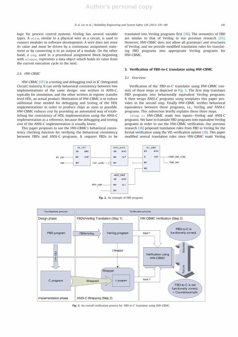
FBD (Function Block Diagram) is one of five standard PLCprogramming languages defined in the IEC 61131-3 standard [2].It consists of an arbitrary number of function blocks connectedtogether with wires similar to that of a circuit diagram. FBD hasbeen widely used for developing software controllers of plants andmachines because of its graphical notations and usefulness inimplementing data flow based applications. For example, the FBDin Fig. 2 consists of 4 function blocks, and the first executedfunction block is GE_DINT while the last one is SEL_DINT.GE_DINT is the function block calculating logical ‘≥’ with twodecimal integer inputs. The whole FBD program is a set of FBDsinterconnected with each other according to their predefinedsequential execution order.
2.3. Verilog
Verilog is one of the most common HDLs (Hardware Descrip-tion Languages) used by IC (Integrated Circuit) designers. Designsmodeled in Verilog are technology independent, easy to developand debug, and considered more readable than schematics. Forthis reason, Verilog is being increasingly used to specify software
RequirementAnalysis Design Implementation
SRSFBD/LD
ProgramsC Programs
ExecutableCodes
AutomaticTranslator
Bisimulation
Equivalence Checking
SimulationUsing C
C Code based Testing
COTSCompiler
?
?
Development process
Techniques for validating "?"
ManualProgramming ?
Fig. 1. RPS software development process using PLCs.
D.-A. Lee et al. / Reliability Engineering and System Safety 120 (2013) 139–149140
Author's personal copy
logic for process control systems. Verilog has several variabletypes. A wire, similar to a physical wire in a circuit, is used toconnect modules in software development. A wire does not storeits value and must be driven by a continuous assignment state-ment or by connecting it to an output of a module. On the otherhand, a reg, used in a procedural assignment block beginningwith always, represents a data object which holds its value fromthe current execution cycle to the next.
2.4. HW-CBMC
HW-CBMC [17] is a testing and debugging tool in IC (IntegratedCircuit) industry. It can verify behavioral consistency between twoimplementations of the same design: one written in ANSI-C,typically for simulation, and the other written in register transferlevel HDL, an actual product. Motivation of HW-CBMC is to reduceadditional time needed for debugging and testing of the HDLimplementations in order to produce chips as soon as possible.HW-CBMC reduces cost by providing an automated way of estab-lishing the consistency of HDL implementation using the ANSI-Cimplementation as a reference, because the debugging and testingcost of the ANSI-C implementation is usually lower.
This paper proposes to use the HW-CBMC's behavioral consis-tency checking function for verifying the behavioral consistencybetween FBDs and ANSI-C programs. It requires FBDs to be
translated into Verilog programs first [30]. The semantics of FBDare similar to that of Verilog in our previous research [31].However, HW-CBMC does not allow all grammars and structuresof Verilog, and we provide modified translation rules for translat-ing FBD programs into appropriate Verilog programs forHW-CBMC.
3. Verification of FBD-to-C translator using HW-CBMC
3.1. Overview
Verification of the ‘FBD-to-C’ translator using HW-CBMC con-sists of three steps as depicted in Fig. 3. The first step translatesFBD programs into behaviorally equivalent Verilog programs.It then wraps ANSI-C programs using templates this paper pro-vides in the second step. Finally HW-CBMC verifies behavioralequivalence between those programs, i.e., Verilog and ANSI-Cprograms. This subsection briefly explains these three steps.
(Step 1) HW-CBMC reads two inputs—Verilog and ANSI-Cprograms. We have to translate FBD programs into equivalent Verilogprograms in order to use the HW-CBMC verification. Our previousresearch [18] proposed translation rules from FBD to Verilog for theformal verification using the VIS verification system [19]. This papermodified several translation rules since HW-CBMC reads Verilog
Fig. 2. An example of FBD program.
Fig. 3. An overall verification process for ‘FBD-to-C’ translator using HW-CBMC.
D.-A. Lee et al. / Reliability Engineering and System Safety 120 (2013) 139–149 141
Author's personal copy
programs which are slightly syntactically different from those for VIS.We implemented the modified rules into ‘FBDtoVerilog 1.0H’ whichare explained in detail in Section 3.2.
(Step 2) HW-CBMC requires users to insert into ANSI-C pro-grams verification properties and codes for reading programs andinitiating the verification. The insertion may incur unexpectedmodification on irrelevant parts, and is a potential threat to thevalidity of the HW-CBMC verification. It is also an error-prone activityto insert properties case-by-case. Thus, we provide a ‘CWrapper’program, wrapping the ANSI-C program with template-basedstatements to prohibit unnecessary modifications and to help usersperform the HW-CBMC verification mechanically. Section 3.3describes the templates-based wrapping process.
(Step 3) Users perform the HW-CBMC verification with twoprograms, a translated Verilog program and a wrapped ANSI-Cprogram. HW-CBMC decides on their behavioral equivalence andproduces ‘success’ or ‘fail’ with a counterexample. The former meansthat the FBD-to-C translator works functionally correctly, while thelatter does not at least for the specific case of the counter-example.
3.2. (Step 1) The FBDtoVerilog translation
3.2.1. Well-formed FBDsWe assume that all FBDs should be well-formed FBDs. If a FBD
is not well-formed, we cannot apply the systematic verificationprocess using HW-CBMC to the FBD, since it is too biased fromtypical FBD programming schemes. An FBD is well-formed, if itsatisfies the assumptions below:
� Assumption 1. EN port of all FBs should be set to enable.FBD programming engineers often use EN and ENO ports ascontrol signals to enable or disable other function blocks. TheIEC 61131-3 standard does not explain the case clearly whenfunction blocks are enabled and disabled subsequently bycontrolling the ports. Furthermore it is not an appropriateusage of FBDs that programmers use the EN port to controlother function blocks as control-flow based languages such as Cand JAVA, because FBD is a data-flow based language. Weassume that all EN ports are set to 1 (TRUE) and they are notallowed to have a connection with others.
� Assumption 2. Explicit data-type conversions should be used.Some FBD software engineering tools allow implicit data-type
conversions such as from INT to BOOL. However, arithmetic orlogical computation among variables which have differenttypes may cause unexpected errors, unless explicit type con-versions do not proceed. We assume that all data-type conver-sions are defined explicitly.
� Assumption 3. Output variables should not be overwritten.An output variable must have a unique name and be assigned onlyonce in a cycle. FBD evaluates outputs at every execution cycle. Ifan FBD generates several different values for the same outputvariable in a cycle, it is a potential cause of unexpected behaviors.
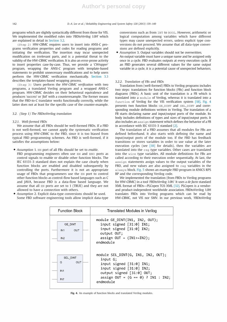
3.2.2. Translation of FBs and FBDsTranslation from (well-formed) FBDs to Verilog programs includes
two steps: translations for function blocks (FBs) and function blockdiagrams (FBDs). A basic unit of the translation is a FB which istranslated into a module of Verilog, whereas it is translated into afunction of Verilog for the VIS verification system [18]. Fig. 4presents two function blocks GE_DINT and SEL_DINT and corre-sponding module definitions written in Verilog. The translation of aFB starts declaring name and input/output ports of the module. Itsbody includes definitions of types and sizes of input/output ports. Italso includes an assign statement which defines the behavior of a FBin accordance with IEC 61131-3 standard [2].
The translation of a FBD assumes that all modules for FBs aredefined beforehand. It also starts with defining the name andinput/output ports of the module too. If the FBD has feedbacktransitions or stores variables in order to use value at the laterexecution cycles (see [18] for details), then the variables aretranslated into the reg type variables. Other cases are translatedinto the wire type variables. All module definitions for FBs arecalled according to their execution order sequentially. At last, theassign statements assign values to the output variables of theFBD, and new values are also assigned to reg variables in thealways block. Fig. 5 shows an example FBD program in KNICS RPSBP and the corresponding Verilog code.
We implemented the translation (from FBDs to Verilog programsfor HW-CBMC) in a tool ‘FBDtoVerilog 1.0H.’ It uses a de facto standardXML format of FBDs—PLCopen TC6 XML [32]. PLCopen is a vendor-and product-independent worldwide association. FBDtoVerilog 1.0Htranslates FBDs into Verilog programs which can be read byHW-CBMC, not VIS nor SMV. In our previous work, ‘FBDtoVerilog
Fig. 4. An example of function blocks and translated Verilog modules.
D.-A. Lee et al. / Reliability Engineering and System Safety 120 (2013) 139–149142

Author's personal copy
1.0’ [18,33] translates FBDs into Verilog programs for verificationusing VIS and SMV [34]. The Verilog programs, however, cannot beused for the HW-CBMC verification, since the model checkers havetheir own restrictions and rules. For example, HW-CBMC cannothandle functions of Verilog whereas VIS and SMV can.
3.3. (Step 2) The ANSI-C wrapping
HW-CBMC reads an ANSI-C program to which verificationproperties and commands are inserted. Step 2 aims to produce theANSI-C program in which all necessary information and commands
are included, using a concept of wrapping with templates. Fig. 6presents the wrapping process, and the output of the process is anANSI-C program wrapped with all necessary information for theHW-CBMC verification. It is structured with 11 templates from T1 toT11 while 3 templates (T3, T7, T10) are optional. It helps usersperform the verification mechanically and prevents frequent non-careful modifications on the ANSI-C programs.
T1. Inclusion of the target ANSI-C file
The wrapping process starts by including a target ANSI-C file.HW-CBMC can execute functions in a “.c” file which has the body of
Fig. 5. A part of FIX_RISING module in KNICS RPS BP and translated Verilog program.
T1Inclusion of thetarget ANSI-C file
T2Definition ofbound variableand declaration ofbasic functions
T3Declaration ofnon-deterministicfunctions
T4Definition of Cstructures toaccess variables inVerilog program
T8The function callof the ANSI-Cprogram
T7Generation ofinput values
T6Declaration anddefinition ofparameters for theANSI-C function
T5The main function
T9Assignments ofinput values tovariables in theVerilog program:set_inputs()
T10Verification ofequivalence:assert(properties)
T11Clocksynchronization
Fixed Elements
ModifiableElements byUsers
bound (T2) times
Fig. 6. A template-based process of wrapping ANSI-C program.
D.-A. Lee et al. / Reliability Engineering and System Safety 120 (2013) 139–149 143
Author's personal copy
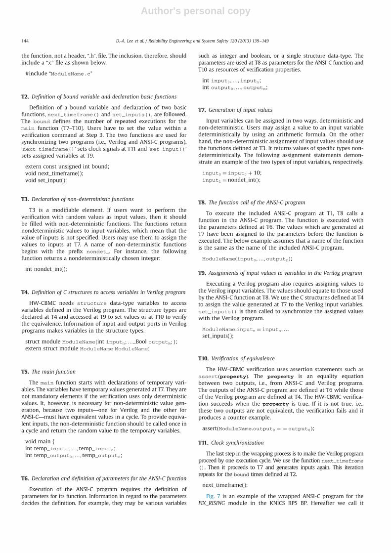
the function, not a header, “.h”, file. The inclusion, therefore, shouldinclude a “.c” file as shown below.
#include “ModuleName.c”
T2. Definition of bound variable and declaration basic functions
Definition of a bound variable and declaration of two basicfunctions, next_timeframe() and set_inputs(), are followed.The bound defines the number of repeated executions for themain function (T7–T10). Users have to set the value within averification command at Step 3. The two functions are used forsynchronizing two programs (i.e., Verilog and ANSI-C programs).‘next_timeframe()’ sets clock signals at T11 and ‘set_input()’sets assigned variables at T9.
extern const unsigned int bound;void next_timeframe();void set_input();
T3. Declaration of non-deterministic functions
T3 is a modifiable element. If users want to perform theverification with random values as input values, then it shouldbe filled with non-deterministic functions. The functions returnnondeterministic values to input variables, which mean that thevalue of inputs is not specified. Users may use them to assign thevalues to inputs at T7. A name of non-deterministic functionsbegins with the prefix nondet_. For instance, the followingfunction returns a nondeterministically chosen integer:
int nondet_int();
T4. Definition of C structures to access variables in Verilog program
HW-CBMC needs structure data-type variables to accessvariables defined in the Verilog program. The structure types aredeclared at T4 and accessed at T9 to set values or at T10 to verifythe equivalence. Information of input and output ports in Verilogprograms makes variables in the structure types.
struct module ModuleNamefint inputn;…_Bool outputm; g;extern struct module ModuleName ModuleName;
T5. The main function
The main function starts with declarations of temporary vari-ables. The variables have temporary values generated at T7. They arenot mandatory elements if the verification uses only deterministicvalues. It, however, is necessary for non-deterministic value gen-eration, because two inputs—one for Verilog and the other forANSI-C—must have equivalent values in a cycle. To provide equiva-lent inputs, the non-deterministic function should be called once ina cycle and return the random value to the temporary variables.
void main {int temp_input0;…; temp_inputn;int temp_output0;…; temp_outputm;
T6. Declaration and definition of parameters for the ANSI-C function
Execution of the ANSI-C program requires the definition ofparameters for its function. Information in regard to the parametersdecides the definition. For example, they may be various variables
such as integer and boolean, or a single structure data-type. Theparameters are used at T8 as parameters for the ANSI-C function andT10 as resources of verification properties.
int input0;…;inputn;int output0;…;outputm;
T7. Generation of input values
Input variables can be assigned in two ways, deterministic andnon-deterministic. Users may assign a value to an input variabledeterministically by using an arithmetic formula. On the otherhand, the non-deterministic assignment of input values should usethe functions defined at T3. It returns values of specific types non-deterministically. The following assignment statements demon-strate an example of the two types of input variables, respectively.
input0 ¼ input0 þ 10;input1 ¼ nondet_intðÞ;
T8. The function call of the ANSI-C program
To execute the included ANSI-C program at T1, T8 calls afunction in the ANSI-C program. The function is executed withthe parameters defined at T6. The values which are generated atT7 have been assigned to the parameters before the function isexecuted. The below example assumes that a name of the functionis the same as the name of the included ANSI-C program.
ModuleNameðinput0;…;outputmÞ;
T9. Assignments of input values to variables in the Verilog program
Executing a Verilog program also requires assigning values tothe Verilog input variables. The values should equate to those usedby the ANSI-C function at T8. We use the C structures defined at T4to assign the value generated at T7 to the Verilog input variables.set_inputs() is then called to synchronize the assigned valueswith the Verilog program.
ModuleName:inputn ¼ inputn;…set_inputs();
T10. Verification of equivalence
The HW-CBMC verification uses assertion statements such asassertðpropertyÞ. The property is an equality equationbetween two outputs, i.e., from ANSI-C and Verilog programs.The outputs of the ANSI-C program are defined at T6 while thoseof the Verilog program are defined at T4. The HW-CBMC verifica-tion succeeds when the property is true. If it is not true, i.e.,these two outputs are not equivalent, the verification fails and itproduces a counter example.
assertðModuleName:output0 ¼ ¼ output0Þ;
T11. Clock synchronization
The last step in the wrapping process is to make the Verilog programproceed by one execution cycle. We use the function next_timeframe(). Then it proceeds to T7 and generates inputs again. This iterationrepeats for the bound times defined at T2.
next_timeframe();
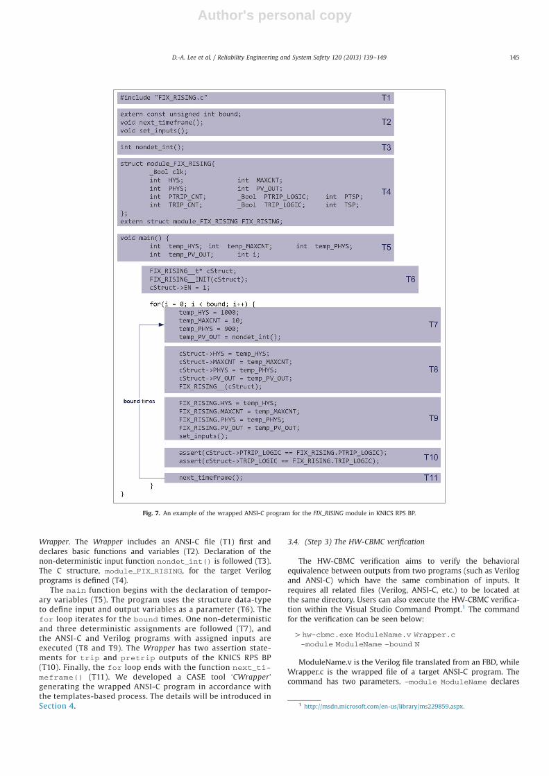
Fig. 7 is an example of the wrapped ANSI-C program for theFIX_RISING module in the KNICS RPS BP. Hereafter we call it
D.-A. Lee et al. / Reliability Engineering and System Safety 120 (2013) 139–149144
Author's personal copy
Wrapper. The Wrapper includes an ANSI-C file (T1) first anddeclares basic functions and variables (T2). Declaration of thenon-deterministic input function nondet_int() is followed (T3).The C structure, module_FIX_RISING, for the target Verilogprograms is defined (T4).
The main function begins with the declaration of tempor-ary variables (T5). The program uses the structure data-typeto define input and output variables as a parameter (T6). Thefor loop iterates for the bound times. One non-deterministicand three deterministic assignments are followed (T7), andthe ANSI-C and Verilog programs with assigned inputs areexecuted (T8 and T9). The Wrapper has two assertion state-ments for trip and pretrip outputs of the KNICS RPS BP(T10). Finally, the for loop ends with the function next_ti-meframe() (T11). We developed a CASE tool ‘CWrapper’generating the wrapped ANSI-C program in accordance withthe templates-based process. The details will be introduced inSection 4.
3.4. (Step 3) The HW-CBMC verification
The HW-CBMC verification aims to verify the behavioralequivalence between outputs from two programs (such as Verilogand ANSI-C) which have the same combination of inputs. Itrequires all related files (Verilog, ANSI-C, etc.) to be located atthe same directory. Users can also execute the HW-CBMC verifica-tion within the Visual Studio Command Prompt.1 The commandfor the verification can be seen below:
4hw-cbmc.exe ModuleName.v Wrapper.c
–module ModuleName –bound N
ModuleName.v is the Verilog file translated from an FBD, whileWrapper.c is the wrapped file of a target ANSI-C program. Thecommand has two parameters. –module ModuleName declares
Fig. 7. An example of the wrapped ANSI-C program for the FIX_RISING module in KNICS RPS BP.
1 http://msdn.microsoft.com/en-us/library/ms229859.aspx.
D.-A. Lee et al. / Reliability Engineering and System Safety 120 (2013) 139–149 145

Author's personal copy
the module name of the Verilog program to read. –bound N
declares the number of iterating cycles from T11 to T7 in thetemplate.
HW-CBMC returns “VERIFICATION SUCCESS” when the twoprograms are behaviorally equivalent. Users can be confident thatthe ANSI-C program generated from an FBD program alwaysshows the same behavior with its origin—FBD program. If theverification fails, HW-CBMC returns “VERIFICATION FAILED” andproduces a counterexample as depicted in Fig. 8.
4. Case study
We applied the proposed process to two PLC programs,FIX_RISING and FIX_FALLING developed by pSET, to demonstrateits feasibility. Table 1 shows information of the two programs forthis case study. The two programs have a similar structure;however, their operations are contrariwise. For example, FIX_RIS-ING generates trip and pretrip signals where one of the inputs hasa value over a set point for more than specific times. The pretripsignal is a warning signal for the trip signal, thus the limitation ofthe pretrip is lower.
We used an automatic translator, ‘pSET2TC6’ [35], which trans-lates the program files of pSET as the PLCopen TC6 XML standard,because pSET does not support the standard. pSET has twodifferent data formats: one is a binary type which is unreadable,and the other is a ASCII type. Although readable, the ASCII type isnot commonly used. Since we developed FBDtoVerilg according tothe PLCopen standard for vendor- and product-independence, it isnecessary to translate the ASCII format to the PLCopen TC6 XMLstandard format.
4.1. Translation of FBD and generation of wrapper
We translated the programs in Table 1 using FBDtoVerilog.FBDtoVerilog has an input file which follows PLCopen TC6 XMLstandard. It produces Verilog files with the same name as the
name of the FBD program according to translation rules asdescribed in Section 3.2. For instance, if a name of the FBD file isFIX_RISING.xml, then FBDtoVerilog produces a FIX_RISING.v file.
CWrapper automatically produces a Wrapper file, Wrapper.c.When CWrapper performs the producing Wrapper, it refers to thetranslated Verilog program to define the C structure as describedat T4 in Fig. 6. CWrapper considers how FBD-to-C translates theFBD to C, because the parameters and function call depend on theC program. pSET translates input and output ports of FBD into astructure data-type of C with suffix __t; it also translates the FBDprogram into a function of C with suffix __ (double underscores).For instance, the input and output ports of FIX_RISING aredefined as a structure data-type FIX_RISING__t; the FIX_RIS-ING is translated into FIX_RISING__(FIX_RISING__t* a__). Thecurrent version of CWrapper is implemented with respect to theANSI-C program translated by pSET.
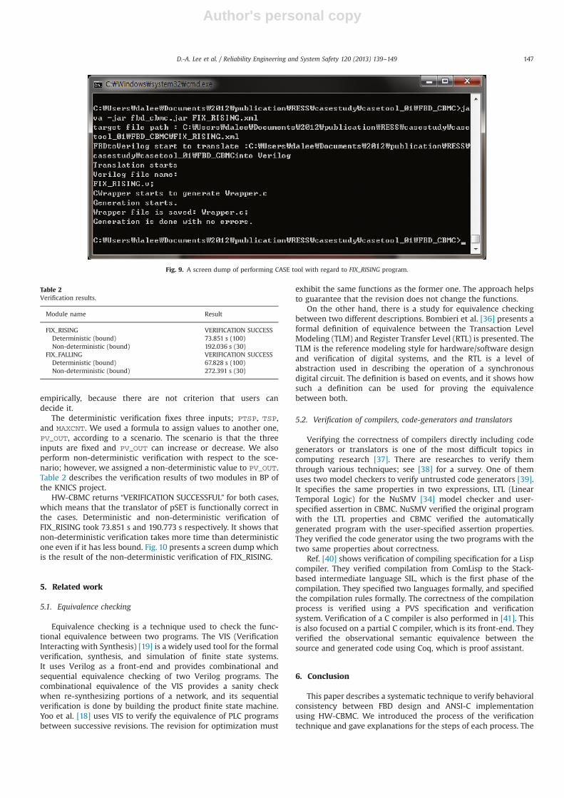
We implemented an execution program to execute FBDtoVerilogand CWrapper. The program is executed with a FBD program, andit executes FBDtoVerilog to translate the FBD program into Verilog.After the translation, it executes CWrapper to produce Wrapper.Fig. 9 presents the execution with the FIX_RISING program.
4.2. Results of HW-CBMC verification
We performed the verification using HW-CBMC in determinis-tic and non-deterministic ways. Verification using non-deterministic functions usually takes more time and additionalmemory space. Furthermore, if number of the bound is too great,then HW-CBMC is shut down abnormally. We chose the bound
Fig. 8. An example of a verification failure and a counterexample produced.
Table 1Information of programs for case study.
Module name # Blocks # Inputs # Outputs (Feedback)
FIX_RISING 26 4 6 (4)FIX_FALLING 26 4 6 (4)
D.-A. Lee et al. / Reliability Engineering and System Safety 120 (2013) 139–149146
Author's personal copy
empirically, because there are not criterion that users candecide it.
The deterministic verification fixes three inputs; PTSP, TSP,and MAXCNT. We used a formula to assign values to another one,PV_OUT, according to a scenario. The scenario is that the threeinputs are fixed and PV_OUT can increase or decrease. We alsoperform non-deterministic verification with respect to the sce-nario; however, we assigned a non-deterministic value to PV_OUT.Table 2 describes the verification results of two modules in BP ofthe KNICS project.
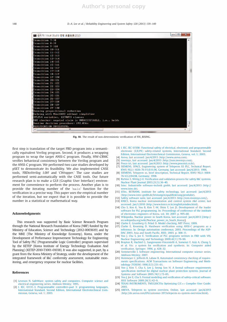
HW-CBMC returns “VERIFICATION SUCCESSFUL” for both cases,which means that the translator of pSET is functionally correct inthe cases. Deterministic and non-deterministic verification ofFIX_RISING took 73.851 s and 190.773 s respectively. It shows thatnon-deterministic verification takes more time than deterministicone even if it has less bound. Fig. 10 presents a screen dump whichis the result of the non-deterministic verification of FIX_RISING.
5. Related work
5.1. Equivalence checking
Equivalence checking is a technique used to check the func-tional equivalence between two programs. The VIS (VerificationInteracting with Synthesis) [19] is a widely used tool for the formalverification, synthesis, and simulation of finite state systems.It uses Verilog as a front-end and provides combinational andsequential equivalence checking of two Verilog programs. Thecombinational equivalence of the VIS provides a sanity checkwhen re-synthesizing portions of a network, and its sequentialverification is done by building the product finite state machine.Yoo et al. [18] uses VIS to verify the equivalence of PLC programsbetween successive revisions. The revision for optimization must
exhibit the same functions as the former one. The approach helpsto guarantee that the revision does not change the functions.
On the other hand, there is a study for equivalence checkingbetween two different descriptions. Bombieri et al. [36] presents aformal definition of equivalence between the Transaction LevelModeling (TLM) and Register Transfer Level (RTL) is presented. TheTLM is the reference modeling style for hardware/software designand verification of digital systems, and the RTL is a level ofabstraction used in describing the operation of a synchronousdigital circuit. The definition is based on events, and it shows howsuch a definition can be used for proving the equivalencebetween both.
5.2. Verification of compilers, code-generators and translators
Verifying the correctness of compilers directly including codegenerators or translators is one of the most difficult topics incomputing research [37]. There are researches to verify themthrough various techniques; see [38] for a survey. One of themuses two model checkers to verify untrusted code generators [39].It specifies the same properties in two expressions, LTL (LinearTemporal Logic) for the NuSMV [34] model checker and user-specified assertion in CBMC. NuSMV verified the original programwith the LTL properties and CBMC verified the automaticallygenerated program with the user-specified assertion properties.They verified the code generator using the two programs with thetwo same properties about correctness.
Ref. [40] shows verification of compiling specification for a Lispcompiler. They verified compilation from ComLisp to the Stack-based intermediate language SIL, which is the first phase of thecompilation. They specified two languages formally, and specifiedthe compilation rules formally. The correctness of the compilationprocess is verified using a PVS specification and verificationsystem. Verification of a C compiler is also performed in [41]. Thisis also focused on a partial C compiler, which is its front-end. Theyverified the observational semantic equivalence between thesource and generated code using Coq, which is proof assistant.
6. Conclusion
This paper describes a systematic technique to verify behavioralconsistency between FBD design and ANSI-C implementationusing HW-CBMC. We introduced the process of the verificationtechnique and gave explanations for the steps of each process. The
Fig. 9. A screen dump of performing CASE tool with regard to FIX_RISING program.
Table 2Verification results.
Module name Result
FIX_RISING VERIFICATION SUCCESSDeterministic (bound) 73.851 s (100)Non-deterministic (bound) 192.036 s (30)
FIX_FALLING VERIFICATION SUCCESSDeterministic (bound) 67.828 s (100)Non-deterministic (bound) 272.391 s (30)
D.-A. Lee et al. / Reliability Engineering and System Safety 120 (2013) 139–149 147
Author's personal copy
first step is translation of the target FBD program into a semanti-cally equivalent Verilog program. Second, it produces a wrappingprogram to wrap the target ANSI-C program. Finally, HW-CBMCverifies behavioral consistency between the Verilog program andthe ANSI-C program. We performed two case studies developed bypSET to demonstrate its feasibility. We also implemented CASEtools, ‘FBDtoVerilog 1.0H’ and ‘CWrapper.’ The case studies areperformed semi-automatically with the CASE tools. Our futureresearch plan is to make a GUI (Graphic User Interface) environ-ment for convenience to perform the process. Another plan is toprovide the iterating number of the ‘main’ function for theverification in a precise way. This paper uses the empirical numberof the iteration, but we expect that it is possible to provide thenumber in a statistical or mathematical way.
Acknowledgments
This research was supported by Basic Science Research Programthrough the National Research Foundation of Korea (NRF) funded by theMinistry of Education, Science and Technology (2012-0003619) and bythe MKE (The Ministry of Knowledge Economy), Korea, under theDevelopment of Performance Improvement Technology for EngineeringTool of Safety PLC (Programmable Logic Controller) program supervisedby the KETEP (Korea Institute of Energy Technology Evaluation AndPlanning) (KETEP-2010-T1001-01038). It was also supported, in part, by agrant from the Korea Ministry of Strategy, under the development of theintegrated framework of I&C conformity assessment, sustainable mon-itoring, and emergency response for nuclear facilities.
References
[1] Leveson N. SafeWare: system safety and computers. Computer science andelectrical engineering series. Addison-Wesley; 1995.
[2] I. IEC, 61131-3. Programmable controllers-part 3: programming languages,International Standard, Second Edition, International Electrotechnical Com-mission, Geneva, vol. 1; 2003.
[3] I. IEC, IEC 61508: Functional safety of electrical, electronic and programmableelectronic (E/E/PE) safety-related systems, International Standard, SecondEdition, International Electrotechnical Commission, Geneva, vol. 1; 2003.
[4] Areva, last accessed: Jan/4/2013 ⟨http://www.areva.com⟩.[5] invensys, last accessed: Jan/4/2013 ⟨http://iom.invensys.com⟩.[6] Posco ict, last accessed: Jan/4/2013 ⟨http://www.poscoict.co.kr⟩.[7] SIEMENS, SPACE, Engineering system of Teleperm XS PLC, Technical Report.
KWU NLL1-1026-76-V1.0/11.96, Germany, last accessed: Jan/4/2013; 1996.[8] SIEMENS, Teleperm xs, brief description, Technical Report. KWU NLL1-1004-
76-V2.2/04.98, Germany; 1998.[9] Richter S, Wittig J-U. Verification and validation process for safety I&C systems.
Nuclear Plant Journal 2003;21(3):36–40.[10] Istec: Industrielle software-technik gmbh, last accessed: Jan/4/2013 ⟨http://
www.istec.de⟩.[11] iSTec, RETRANS, institute for safety technology, last accessed: Jan/4/2013
⟨http://www.istec-gmbh.de/leistungen/qualifizierung/produkte⟩.[12] Safety software suite, last accessed: Jan/4/2013 ⟨http://iom.invensys.com/⟩.[13] KNICS, Korea nuclear instrumentation and control system r&d center, last
accessed: Jan/1/2010 ⟨http://www.knics.re.kr/english/eindex.html⟩.[14] Cho S, Koo K, You B, Kim T.-W, Shim T, Lee JS. Development of the loader
software for PLC programming. In: Proceedings of conference of the instituteof electronics engineers of Korea, vol. 30; 2007. p. 995–60.
[15] Wikipedia, Nuclear power in South Korea, last accessed: Jan/4/2013 [⟨http://en.wikipedia.org/wiki/Nuclear_power_in_South_Korea⟩].
[16] Clarke E, Grumberg O, Peled D. Model checking. MIT Press; 1999.[17] Clarke E, Kroening D. Hardware verification using ANSI-C programs as a
reference. In: Design automation conference, 2003. Proceedings of the ASP-DAC 2003. Asia and South Pacific, IEEE; 2003. p. 308–11.
[18] Yoo J, Cha S, Jee E. Verification of PLC programs written in FBD with VIS.Nuclear Engineering and Technology 2009;41(1):79–90.
[19] Brayton R, Hachtel G, Sangiovanni-Vincentelli A, Somenzi F, Aziz A, Cheng S,et al. Vis: a system for verification and synthesis. In: Computer aidedverification. Springer; 1996. p. 428–32.
[20] Sommerville I. Software engineering. International computer science series.Addison-Wesley; 2007.
[21] Heitmeyer C, Jeffords R, Labaw B. Automated consistency checking of require-ments specifications. ACM Transactions on Software Engineering and Meth-odology (TOSEM) 1996;5(3):231–61.
[22] Yoo J, Kim T, Cha S, Lee J, Seong Son H. A formal software requirementsspecification method for digital nuclear plant protection systems. Journal ofSystems and Software 2005;74(1):73–83.
[23] Yoo J, Jee E, Cha S. Formal modeling and verification of safety-critical software.IEEE Software 2009;26(3):42–9.
[24] TEXAS INSTRUMENTS, TMS320C55x Optimizing C/C++ Compiler User Guide;2003.
[25] AREVA, Teleperm xs system overview, Online, last accessed: Jan/4/2013⟨http://de.areva.com/EN/customer-397/teleperm-xs-system-overview.html⟩.
Fig. 10. The result of non-deterministic verification of FIX_RISING.
D.-A. Lee et al. / Reliability Engineering and System Safety 120 (2013) 139–149148

Author's personal copy
[26] Pezzè M, Young M. Software testing and analysis: process, principles, andtechniques. Wiley; 2008.
[27] I. Rational, Rational rhapsody, last accessed: Jan/4/2013 ⟨http://www-01.ibm.com/software/awdtools/rhapsody/⟩.
[28] Lee D, Yoo J, Lee J. Equivalence checking between function block diagrams andC programs using HW-CBMC. Computer Safety, Reliability, and Security2011:397–8.
[29] Huang H, Cheng K. Formal equivalence checking and design debugging,Frontiers in electronic testing; FRET 12. Kluwer Academic; 1998.
[30] IEC/IEEE behavioural languages—part 4: Verilog hardware description lan-guage (adoption of IEEE STD 1364-2001), IEC 61691-4 First edition 2004-10;IEEE 1364 (2004) 0–860.
[31] Jee E, Jeon S, Cha S, Koh K, Yoo J, Park G, et al. FBDVerifier: interactive andvisual analysis of counter-example in formal verification of function blockdiagram. Journal of Research and Practice in Information Technology 2010;42(3):171–88.
[32] PLCopen for efficiency in automation, last accessed: Jan/4/2013 ⟨http://www.plcopen.org⟩.
[33] Yoo J, Lee J, Jeong S, Cha S. FBDtoVerilog: a vendor-independent translationfrom fbds into verilog programs. In: The twenty-third international confer-ence on software engineering and knowledge engineering (SEKE 2011); 2010.p. 48–51.
[34] Cimatti A, Clarke E, Giunchiglia F, Roveri M. Nusmv: a new symbolic modelverifier. In: Halbwachs N, Peled D, editors. Computer aided verification.Lecture notes in computer science, vol. 1644. Berlin, Heidelberg: Springer;1999. p. 495–9.
[35] Lee D-A, Yoo J. pSET2TC6: a translation tool to standardize the output formatof pSET. In: Korean institute of information scientists and engineers (KIISE)2011, vol. 38; 2011. p. 105–7.
[36] Bombieri N, Fummi F, Pravadelli G, Marques-Silva J. Towards equivalencechecking between TLM and RTL models. In: Fifth IEEE/ACM internationalconference on formal methods and models for codesign, 2007. MEMOCODE2007, IEEE; 2007. p. 113–22.
[37] Hoare T. The verifying compiler: a grand challenge for computing research.Modular Programming Languages 2003:25–35.
[38] Dave M. Compiler verification: a bibliography. ACM SIGSOFT Software Engi-neering Notes 2003;28(6) 2–2.
[39] Staats M, Heimdahl M. Partial translation verification for untrusted code-generators. Formal Methods and Software Engineering 2008:226–37.
[40] Dold A, Vialard V. A mechanically verified compiling specification for a lispcompiler. FST TCS 2001: Foundations of Software Technology and TheoreticalComputer Science 2001:144–55.
[41] S. Blazy, Z. Dargaye, X. Leroy, Formal verificationof a C compiler front-end,FM 2006: Formal Methods 2006: 460–75.
D.-A. Lee et al. / Reliability Engineering and System Safety 120 (2013) 139–149 149