augmented reality for product packaging - simple...
TRANSCRIPT

Bachelor thesis
HuvudområdeComputer Engineering
Augmented Reality for Product PackagingAn Android Augmented Reality App
Sam Nikobonyadrad
Augmented Reality for Product PackagingSam Nikobonyadrad 2012-05-30
AbstractAugmented Reality for smartphones, while still in its initial stages, has a great potential in relation to the future path of mobile marketing and has already shown significant market presence thus far. However, Augmented Reality is an almost new concept, but its basis and techniques have been used for years. By generating enthusiasm in the retail market, Augmented Reality presents many opportunities. Simulating virtual interaction in real-time for an unknown product, encourages customers to experience an advertisement. The sense enhancement that Augmented Reality provides over a real-world environment, might be either the result of the device's location or the environmental images surrounding the device. The latter is called vision Augmented Reality.
This study aims to develop a vision-based Augmented Reality application for Android platforms. The idea is based on a proposal offered by a Product Packaging company, which would like to develop a smartphone application in order to provide shoppers an idea regarding what is inside the package. However, this is only one of the numerous advantages that AR brings and the benefits of this technology appears to be almost limitless in relation to increasing productivity for customers. Once the goal has been achieved, the application can be used to provide relevant information about the product such as physical specification, ingredients, animated instruction manual, repair wizard and so on.
The main focus of the entire implementation is on integrating an existing AR SDK and a Java rendering library so that they can cooperate together. In addition, the fundamentals associated with the Image Registration process, which is the basis of Augmented Reality, are addressed. Both the advantages and drawbacks of the implementation model are discussed in this paper as are the problematic issues surrounding the execution steps.
Keywords: Augmented Reality, Packaging, Android, Image Registration, Vuforia (QCAR), jPCT-AE, OpenGL ES, Computer Vision, Product Packaging
ii

Augmented Reality for Product PackagingSam Nikobonyadrad 2012-05-30
AcknowledgmentsFrom a technical perspective, I would like to thank Kimberly Siva in Qualcomm Developer's Guide team for her invaluable support and Egon Olsen, administrator of jPCT-AE forum, not only for producing such a good product, but also in providing useful assistance.
On a personal note, I want to thank my parents for their consistent encouragements and supports. Also, special thanks to Dr. Ulf Jennegah, my thesis supervisor, for giving me the opportunity to work on this project and his guidance.
iii
Augmented Reality for Product PackagingSam Nikobonyadrad 2012-05-30
Table of ContentsAbstract...............................................................................................................ii
Acknowledgments.............................................................................................iii
Terminology.......................................................................................................vi
1 Introduction...............................................................................................11.1 Background and problem motivation.....................................................11.2 Overall aim.............................................................................................21.3 Scope......................................................................................................21.4 Detailed problem statement....................................................................21.5 Outline....................................................................................................3
2 Theory........................................................................................................42.1 Computer Vision and AR.......................................................................42.2 Image Registration.................................................................................42.2.1 Feature point......................................................................................52.2.2 Feature detection...............................................................................62.2.3 Feature description (extraction).........................................................62.2.4 Feature matching...............................................................................82.2.5 Feature tracking.................................................................................92.3 Natural feature detection and tracking...................................................9
3 Methodology............................................................................................123.1 Principles..............................................................................................123.2 Preparation and Tools...........................................................................123.3 Performance Test..................................................................................14
4 Implementation.......................................................................................164.1 Overview..............................................................................................164.2 OpenGL ES 1.1 or 2.0?........................................................................174.3 Application structure ........................................................................174.4 Coding..................................................................................................174.4.1 GLSurfaceView...............................................................................194.4.2 ModelView Matrix .........................................................................204.4.3 Projection Matrix.............................................................................214.4.4 Loading 3D models asynchronously...............................................224.4.5 Memory usage improvement...........................................................234.5 Modeling .............................................................................................23
5 Results......................................................................................................255.1 Application screenshots........................................................................255.2 Efficient distance..................................................................................265.3 Efficient tilt angle.................................................................................265.4 3D Model loading time ......................................................................27
6 Discussion.................................................................................................286.1 Limitations...........................................................................................28
iv

Augmented Reality for Product PackagingSam Nikobonyadrad 2012-05-30
6.2 Conclusion............................................................................................28
References.........................................................................................................30
v

Augmented Reality for Product PackagingSam Nikobonyadrad 2012-05-30
Terminology
Acronyms
AR Augmented Reality
VR Virtual Reality
MR Mixed Reality
PTAM Parallel Tracking and Mapping
SLAM Simultaneous localization and mapping
FAST Features from Accelerated Segment Test
SURF Speed-ed Up Robust Feature
SIFT Scale Invariant Feature Transform
SSD Sum of Squared Differences
RANSAC Random Sample Consensus
QCAR Qualcomm Augmented Reality SDK
FOV Field of View
DoG Difference of Gaussians
vi
Augmented Reality for Product PackagingSam Nikobonyadrad 2012-05-30
1 IntroductionAugmented Reality (AR) is a term that applies to the enhancing the user perception of the real world with virtual elements. Unlike Virtual Reality (VR), which involves simulating a virtual environment with a physical presence, AR does not require special equipments and can be implemented by means of a simple capturing device e.g. a digital camera and a means of coating computer-designed objects over the camera’s pictures.
Both AR and VR fall within the field of the more general context Mixed Reality (MR). Mixed Reality refers to the merging of the real and virtual worlds to produce new environments and visualizations in which physical and digital objects co-exist and interact in real time [1]. AR brings a new hybrid perspective for the user, which is a combination of the real world as sensed by the user and a virtual scene generated by a computer. Because of this capability, many applications have already taken advantages of AR technology to provide a more subtle and information-rich experience for the users. Flight simulators, medical visualizations, video games, military training and many more, fall within the AR application domain, which is then divided into two main categories: Location-based AR and Vision-based AR.
Due to the low requirements and availability, AR technology is a growing field in the area of smartphones. A typical vision-based AR application is usually formed from an input device such as a digital camera, image processing and tracking, which are performed by a computer, rendering, which is achieved by means of a Graphics Processing Unit (GPU) and, lastly, a display surface in order to view the real environment overlaid by the virtual elements. Basically, an AR system looks for a predefined pattern in its databank in order to discover a match and then informs the rendering engine to draw the graphics. Sometimes this can be achieved by taking a photo and post-processing it in order to investigate any patterns, but sometime, it is desirable to examine a video stream in real-time which is the focus of this project. Today’s smartphones are able to perform these within their small shape and size along with their superior portability. This is why AR applications are receiving greater attention from the mobile developers and the companies which are able to benefit from AR applications. This project intends to investigate an Augmented Reality application for Android smartphones in order to increase the productivity and improve the customer experiences.
1.1 Background and problem motivation
Packaging is a chained procedure that involves a design process, storage, installation, distribution and transport of products in order to make them ready to buy and use. Nowadays, packaging is more a science than a simple production line. Companies attempt to improve the sustainability of their
1
Augmented Reality for Product PackagingSam Nikobonyadrad 2012-05-30
product's package in order to increase its life cycle and reduce the environmental impact. But at the same time they are willing to make easy-to-use and easy-to-assemble packages and this is the point at which an AR application can play a role. Imagine an IKEA package that requires reading the entire assembly instructions step by step in order to make it work. Reading the manual often appears to be an onerous task. Instead, an AR application can be used to detect a specific package and play an animated assembly instruction over it which is much easier for users to understand and follow.
1.2 Overall aim
The project aims to introduce a practical use of Augmented Reality and expose its capabilities and weaknesses in the smartphone’s domain. Additionally, this project examines how handy and useful an AR-enabled application can be with the incorporation of a business-class application in the market place. Since the AR technology involves different areas such as Image Recognition, Real-time Tracking and Computer Graphics, reading this report offers a brief introduction regarding how multiple technologies can be incorporated in order to develop a brand new and pristine technology.
1.3 Scope
The project has its focus on vision-based AR technologies and toolkits supported by Android platforms for the image processing and object detection part. Obviously, this step involved accessing a device camera in order to obtain the image preview for further processing. Secondly, for the graphic part, OpenGL API is used to render the graphics. This is the first and main phase of this project and if successful will enable the addition of many other details which can be performed at a later stage.
1.4 Detailed problem statement
The main deliverable of this study is an Android application utilizing an existing vision-based Augmented Reality technique to assist the users to have a better understanding of different products. The application will be able to detect a “product” in real-time by inspecting its package appearance through the pictures received from the camera and then superimpose relevant graphics or additional information on the screen. The graphics might be anything (specification, ingredients, set-up instruction and ...) that describes the product in a visualized manner. However, this is the main purpose of this project but, there are also further details to be added at a later stage. Details include adding an administrative interface to update and maintain the trackables object as well as virtual objects.
The goals of the project can be summarized into following substantial key-points:
• What are Augmented Reality fundamentals and how does it work?
2
Augmented Reality for Product PackagingSam Nikobonyadrad 2012-05-30
• How may a Product Packaging company benefit from AR?
• How can an AR system be mixed with a Rendering engine?
• How practical is the final result for Android smartphones?
• How good is the performance of the application?
1.5 Outline
Chapter 2 describes the fundamentals of an AR system by addressing Computer Vision's techniques and algorithms with the emphasis on Image Registration. Chapter 3 presents the methodology and model of the implementation and a brief survey with regards to choosing the best tools and software to work with. Chapter 4 explains the step-by-step integration and coding procedure. Chapter 5 displays the final application along with performance test statistics. Chapter 6 concludes the study by analyzing the results and describing the shortages and offers future improvements.
3
Augmented Reality for Product PackagingSam Nikobonyadrad 2012-05-30
2 TheoryThis chapter describes the AR fundamentals and key concepts with regard to the scope of the study. Since there are a variety of techniques and algorithms involved in AR technologies, it will be sufficient to deal with those that actually have a link to this project.
2.1 Computer Vision and AR
It is almost impossible to study an AR experience without mentioning Computer Vision. Computer vision is a field that includes methods for acquiring, processing, analyzing, and understanding images and, in general, high-dimensional data from the real world in order to produce numerical or symbolic information [2]. Human vision can discern and track three-dimensional structure of an object in a real environment in an ostensibly simple manner. It is possible distinguish the shape, color, position, angle and transparency of an object even through a delicate pattern of lights and shading. It is also possible to outline an object and segment it out from the background with almost no effort. However, in computer vision, despite all the advances and reliable techniques, the ability to achieve at this level of perfection remains elusive [3].
The question may be asked as to how AR can benefit from Computer Vision and the quick answer is that, basically AR is, to some degree, an application of Computer Vision. One of the key criteria that makes a distinction between different AR technologies is how realistically they merge augmentations with real environment. For this reason, it is important to determine how accurately the computer vision algorithm is able to operate. As stated previously, any AR system includes a means for image recognition and image tracking, which in area of computer vision is called Image Registration [4].
2.2 Image Registration
Image registration is the process of spatially overlaying a set of images which are taken under different conditions such as, different times, different angles, different sensors and different viewpoints into one coordinate system [5][6][7]. In other words, the process must be able to extract the coordinates of an image independent from camera and determine a transformation that aligns the given images [4][8]. Basically, in this process, there is an initial image, with known geometry, which is called reference image and the other images, which will establish a correlation to a reference, are called sensed image [4][6].
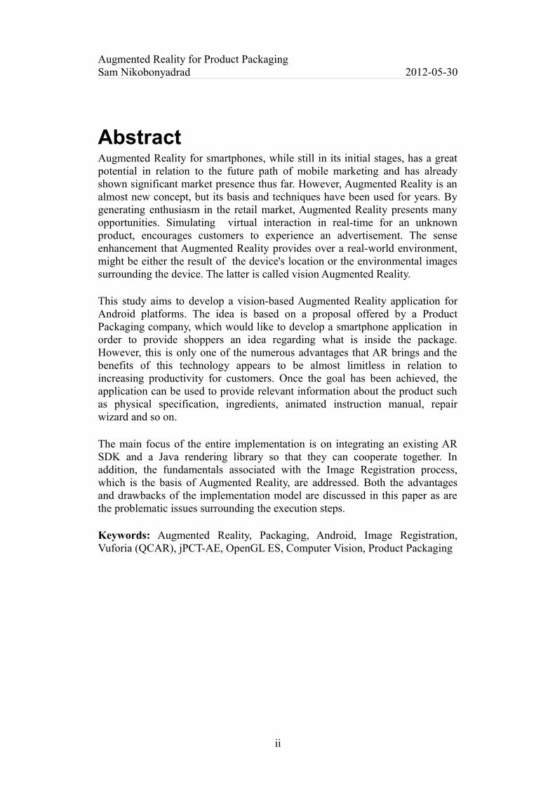
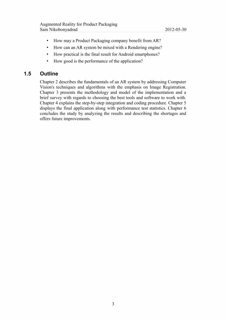
Figure 1 shows the general principle of the image registration procedure. The ultimate goal of image registration, as mentioned previously, is to estimate the spatial transformation that can be used to modify one image in order to align it with another image. As can be seen in the figure, there are some points marked
4
Augmented Reality for Product PackagingSam Nikobonyadrad 2012-05-30
with a plus sign in both images. These are simply called feature-points which will be covered later in this chapter. It is also possible to conduct the image registration without prior knowledge of the scene geometry [4]. In this approach, locations of 3D points are calculated based on a given set of correspondences between image features points [3].
a á b´
b
Figure 1: General principle of Image Registration
This process usually includes estimating 3D geometry, representing structure, and camera pose, representing motion, simultaneously and hence it is called structure from motion [3]. Various methods have been implemented for extracting the 3D structure from motion including Bundle adjustment, Parallel Tracking and Mapping (PTAM), Simultaneous localization and mapping (SLAM) etc. that are mainly relied on mathematical methods such as triangulation, factorization, projective geometry, and exponential map [3][4]. Structure from motion methods are beyond the scope of this project and the focus here is on image registration with a known and pre-calculated 3D structure of the scene.
2.2.1 Feature point
In image registration process, images are compared by their features. Features provide crucial information for recognition and matching purposes and measure different characteristics of an image such as geometry, spatial, algebraic etc. It is more convenient and robust to compare image features in order to measure the level of similarity rather than comparing every single pixel [6]. There is no general or precise definition regarding what constitutes a feature and they mostly depend on the type of application that will be used in [9]. However, generally, features are the most solid and impervious key areas of an image which stay invariant to changes in geometry, noise, contrast, lights and sensors [6]. Feature detection and extraction is the initial and key step of many computer vision algorithms. As a result different algorithms are evaluated by how fast, accurate and efficient they are in extracting features [9]. In summary, features must be highly distinctive, easy to detect and extract, and be able to endure changes in illumination, noise, uniform scale, change in viewing angle, translation and rotation.
5

Augmented Reality for Product PackagingSam Nikobonyadrad 2012-05-30
2.2.2 Feature detection
The expected result of a feature detection step often appears as a collection of isolated points and patches (corners), edges, lines, continuous curves or contiguous regions [9]. Feature detector algorithms are roughly classified into three groups: Edge detection, Corner detection, Blob detection and each of these has its own usability and application. Figure 2 shows the output result of applying a corner detection algorithm called FAST (Features from Accelerated Segment Test) to our sample image in MATLAB. By means of a detailed look, it is possible to see that texture-less areas have not been marked and, in addition, the majority of the selected feature patches have visible contrast changes (gradient) [3]. Moreover it is not easy to localize the patches with a straight line in a single direction [3]. These are a few considerations that every feature detection algorithm must adhere to, so the selected features carry the most information about the image.
Figure 2: Corner detection with FAST algorithm in MATLAB
Another common feature detection algorithm is SURF (Speed-ed Up Robust Feature) which is known for its robustness and was originally developed by Herbert Bay. OpenCV, which is a well-known library aimed at real time computer vision, has implemented SURF for feature extraction [10].
2.2.3 Feature description (extraction)
Once the feature points have been detected, it is necessary to extract a local window of image with the detected feature point at the center. This is called the feature descriptor, which is an abstract representation of the image and will be used later to determine the correspondence between the reference image and the sensed image [6][9]. Because the input data for the Image Registration algorithm is too large for post-processing and it is also expected to be excessively redundant, it is necessary to prune the input data to a simpler representation [11]. This is the main intention of the feature extraction stage and the result would include less data carrying most information.
6
Augmented Reality for Product PackagingSam Nikobonyadrad 2012-05-30
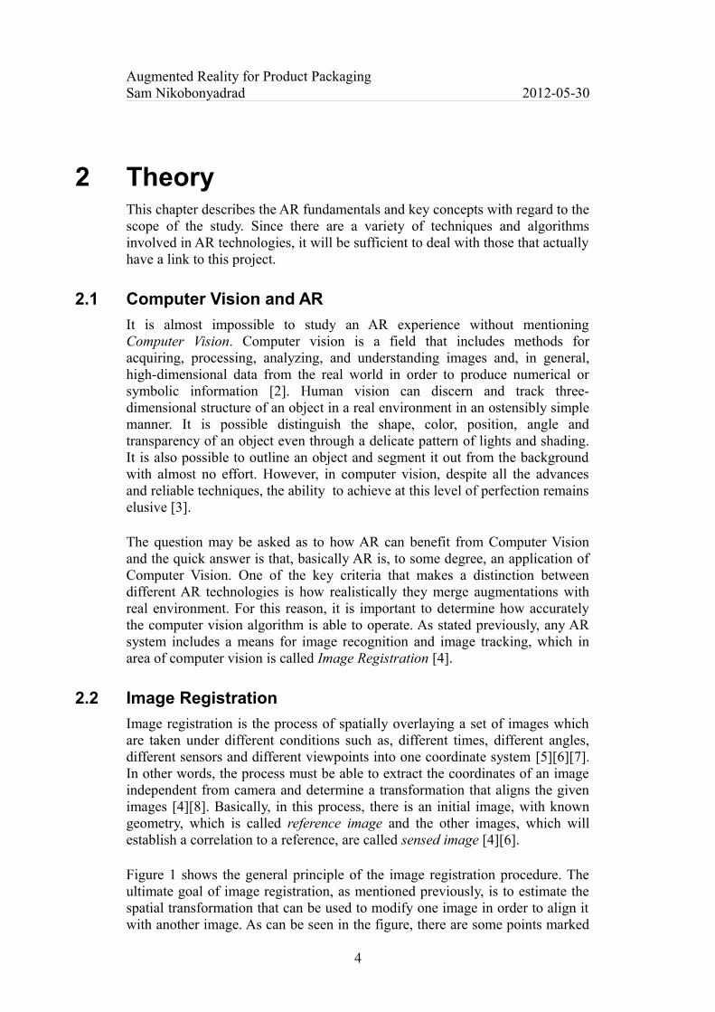
Figure 3 is a schematic diagram of the extracted descriptors based on the SIFT (Scale Invariant Feature Transform) algorithm. SIFT computes a 4x4 eight-bin orientation histogram to represent 16x16 pixel feature patches [3]. If the sensed images have no rotation, scale or affine deformation, establishing the correspondence and finding similarities can be easily performed. However, this is the least likely scenario since what is being dealt with is a number of shifty conditions. In order to build scale and rotation invariant descriptors, several approaches have been proposed of which SIFT is one. Others are Histogram-Based, Spin-Image-Based, Filtering-Based, Moment-Based and Composite descriptor. Explaining the details of the aforementioned algorithms is beyond the scope of this report therefore a brief description of the concept is adequate.
Figure 3: A schematic representation SIFT descriptor [3]
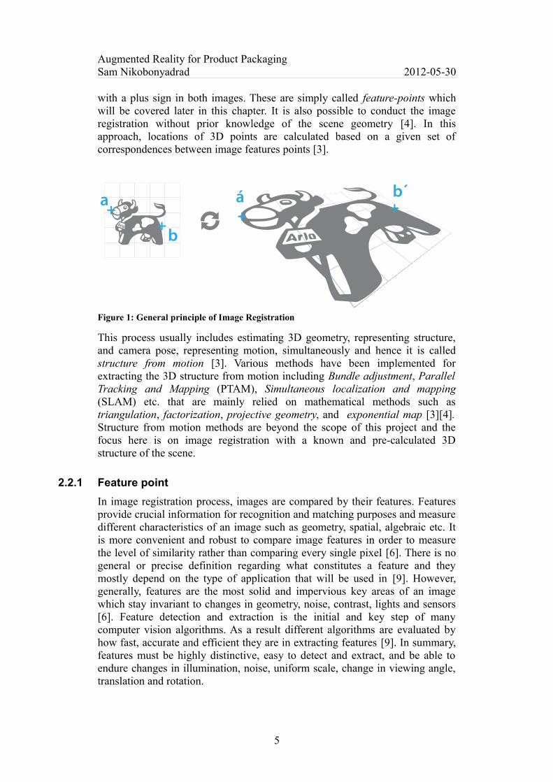
Actually, SIFT can perform this in only a few steps. Firstly, it applies Difference of Gaussians (DoG) to the image so as identify the features that are invariant to scale or orientation. Figure 4 shows the result of applying DoG to the sample image [11].
Figure 4: Before DoG operator (left), After DoG applied (right) using GIMP software
After this step, SIFT analyzes the features to find the location and scale and then determines the orientation by means of a local gradient direction. Figure 5 displays how the orientations are shaped by resultant vectors of the gradient directions for each of the feature points. Finally, the features will be transformed into the representation (orientation histogram) that is displayed by Figure 3. This is the squeezed instance of information which any comparison relies on.
7

Augmented Reality for Product PackagingSam Nikobonyadrad 2012-05-30
Figure 5: Extracting local gradient direction [12]
2.2.4 Feature matching
The next step, after computing the descriptor, is to find the match between the reference image descriptors and the sensed descriptors. By having both descriptors, it is possible to find the closest (most similar) or least dissimilar match. However because it is likely that there is inaccurate information in descriptors, some of the established correspondences may be incorrect as not all features can resist the changes in image.
Figure 6: Corner detection with FAST algorithm in MATLAB
Figure 6 again shows the feature points detected by the FAST algorithm in MATLAB applied to the sample image and its deformed version. It is now time to pick the correspondences between the features derived above. For each feature a 9x9 block with the feature at the center has been extracted as a descriptor. Figure 7 is the output result of matching features with the matching cost of the Sum of Squared Differences (SSD) [13]. As can be seen many of the correspondences acquired in this step are incorrect. But it is still possible to find the transformation parameter by using the Random Sample Consensus (RANSAC) algorithm [13]. “The process of selecting a small set of seed matches and then verifying a larger set is often called random sampling or RANSAC” [3]. An interesting hint to note is that, by considering only the correct correspondences it is possible to estimate the transformation parameter with the assistance of Geometry Constraint which holds between the features set [6].
8

Augmented Reality for Product PackagingSam Nikobonyadrad 2012-05-30
Figure 7: Matched correspondences with SSD metric between respective regions
2.2.5 Feature tracking
What has been performed thus far has been the detection of the features in each image independently and an attempt made to match the descriptors in order to discover the correspondences. For AR related applications, however, there is a video stream for which all of these steps must be applied in real time. Hence, instead of detecting the features for each frame and then computing the descriptor, there is a better technique known as Feature Tracking [3]. In this approach, the feature detection step is not done individually, instead, features of the reference image will be detected and extracted beforehand and then subsequent frames will be investigated for similar correspondences which can be compared with the reference. Feature tracking is implemented to a significant extent for video tracking mainly because, the amount of change in motion and appearance of features in juxtaposed frames is supposed to be minor [3]. For the scenarios in which the search through image falls within a very large range, the use of a hierarchical search strategy can speed up the tracking such that the process starts by searching a low-resolution version of images for the initial decisions [3].
2.3 Natural feature detection and tracking
Mobile phones are a low performance platform with highly restrictive resources compared to PCs. Consequently, their limitations in any aspect must be taken into account while developing an AR technology. Many AR solutions, that are specially designed for mobile phones, use marker-based tracking for pose estimation and coordinate extraction. This approach, while it works sufficiently well and simplifies the tracking process, is not friendly for the end-user of the technology because the environment must be prepared beforehand. For this reason it is preferable to rely on features that are naturally present in the image.
9

Augmented Reality for Product PackagingSam Nikobonyadrad 2012-05-30
This makes the development procedure complicated but brings flexibility so that every object with sufficiently-detailed texture can be easily tracked [14].
In this method the necessary information for tracking purposes can be obtained by means of optical-flow-based template matching or feature correspondences [14]. “Optical flow or optic flow is the pattern of apparent motion of objects, surfaces, and edges in a visual scene caused by the relative motion between an observer (an eye or a camera) and the scene” [15]. Feature correspondences work better and are more effective than template matching because they depend on matching locally present features. Considering such correspondences, the pose can be roughly calculated by robust estimation which makes it fairly insensitive to partial occlusion, blur, reflection, scale change, tilt, illumination change or matching errors [14][16].
One of the well-implemented natural feature tracking approaches [17] is based on a modified version of SIFT and FERNS feature descriptors. SIFT is robust but is processor intensive due to its computational cost, while FERNS uses feature classification, which is fast but requires a large memory capacity. In this implementation SIFT and FERNS have been integrated, but with significant modification to make a suitable tracking system for mobile phones.
Figure 8: SIFT and FERNS pipeline (abstract) [17]
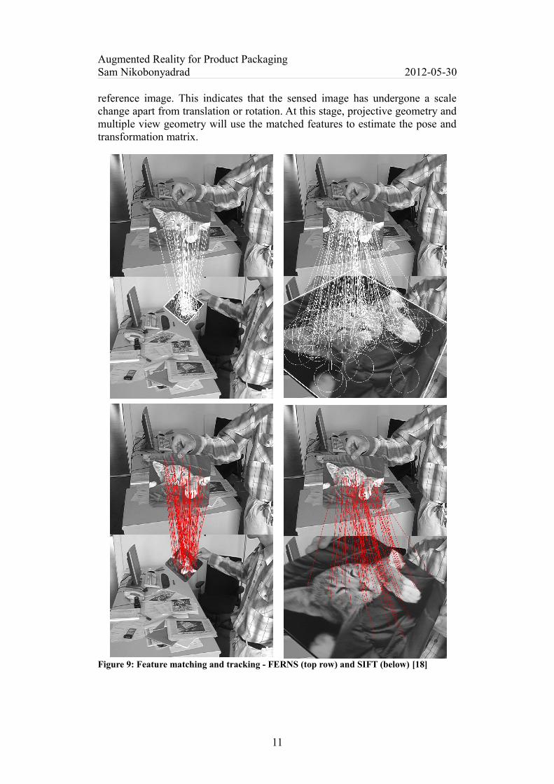
Figure 8 illustrates the summarized pipeline of the aforementioned tracking technique. In order to compute the descriptor surrounding feature points, FERNS uses hundreds of simple binary features and models class posterior probabilities which allows it to perform sufficiently well even with significant perspective changes [18].
Figure 9 shows both FERNS (top row) and SIFT (bottom row) obtained matches in a few frames. In each row it is possible to see the reference image at the top and the sensed frames below. According to the study by Ecole Polytechnique University [18], FERNS match the features to the same extent as SIFT and often to an even greater extent. By looking at the pictures it can be noted that, the interval between the features points increases in the pictures at right and they are tightened in the pictures at the left as compared to the
10
Feature Detection
Pose estimation
Feature Tracking (optional)
Descriptor creation and matching
Image Blur
Classification
FERNSSIFT
Augmented Reality for Product PackagingSam Nikobonyadrad 2012-05-30
reference image. This indicates that the sensed image has undergone a scale change apart from translation or rotation. At this stage, projective geometry and multiple view geometry will use the matched features to estimate the pose and transformation matrix.
Figure 9: Feature matching and tracking - FERNS (top row) and SIFT (below) [18]
11
Augmented Reality for Product PackagingSam Nikobonyadrad 2012-05-30
3 MethodologyThis chapter addresses the methodology of development procedure's plan and the process of choosing the best tools to satisfy the implementation requirements and the project's goal.
3.1 Principles
Basically, any consideration for design and implementation of this project is based on web resources, journals, articles, books and personal experiences. Since the outcome of this project was supposed to be a polished end-user application, to be used in real market, and not a research-quality code, the cost of implementation was a major concern. Thus it was preferable to use free/open-source tools so as preserve the cost of implementation at a minimum. The methodology of this project is Incremental development such that it is broken into smaller pieces, which were being implemented concurrently and later were put together during the final stage. A Trial and Error approach was also used in such a way that if any part of the project required review or modification, it was possible to step back and resolve it and then return to the leaving point again.
3.2 Preparation and Tools
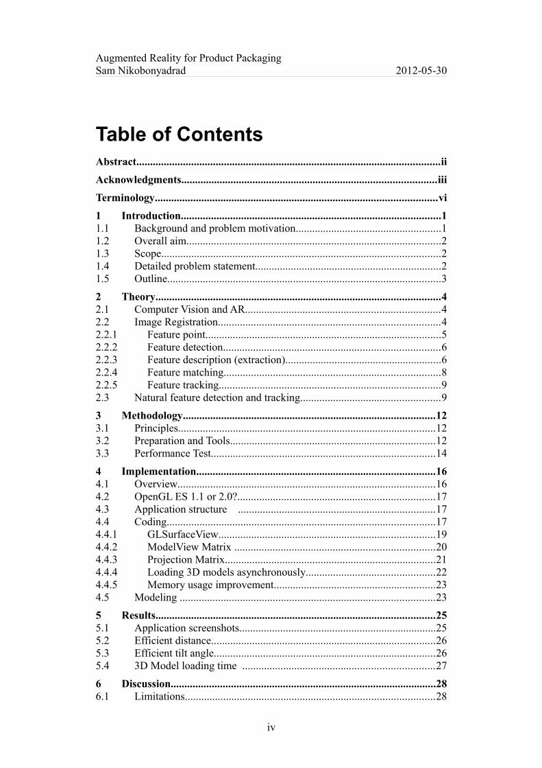
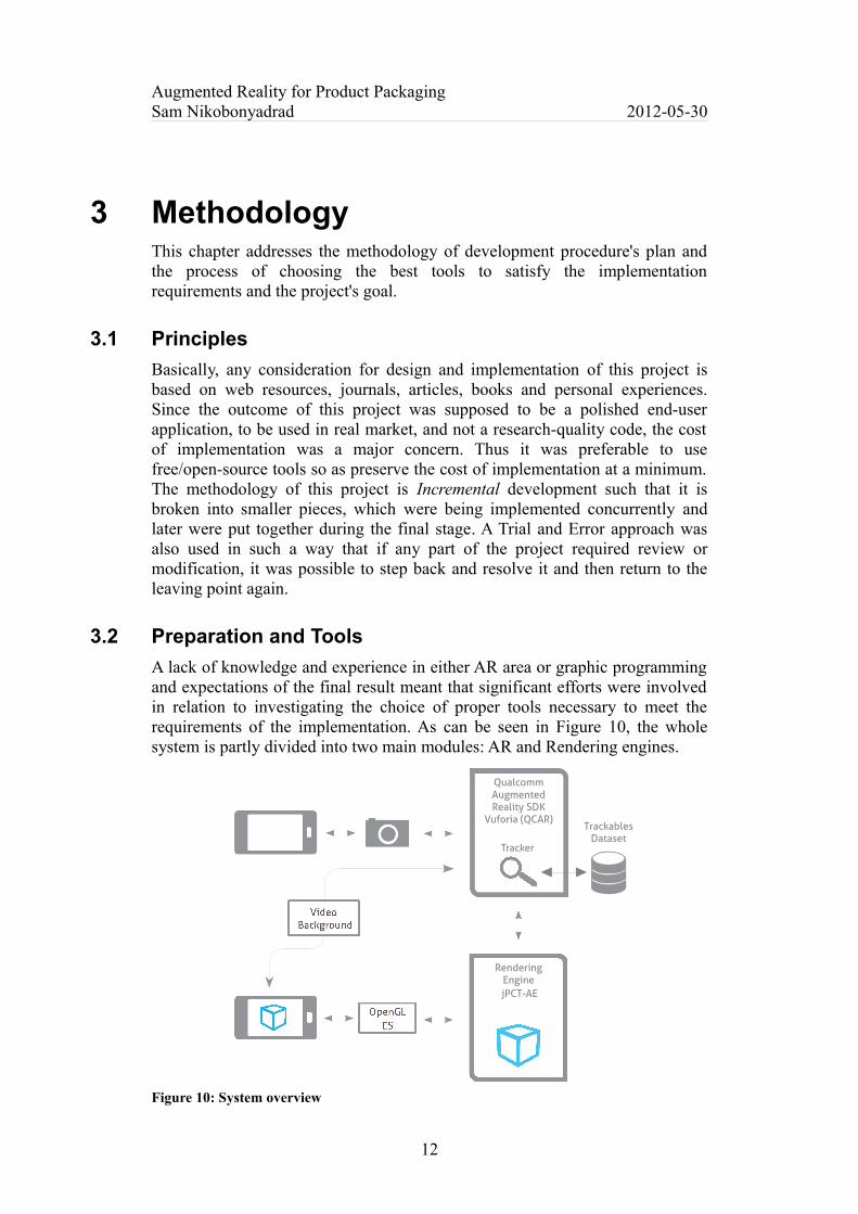
A lack of knowledge and experience in either AR area or graphic programming and expectations of the final result meant that significant efforts were involved in relation to investigating the choice of proper tools necessary to meet the requirements of the implementation. As can be seen in Figure 10, the whole system is partly divided into two main modules: AR and Rendering engines.
Figure 10: System overview
12
Qual c omm Augmented R eality SDK
V u f oria (QCAR)
T r ac k er
R endering EnginejPCT-AE
Trackables Dataset
Augmented Reality for Product PackagingSam Nikobonyadrad 2012-05-30
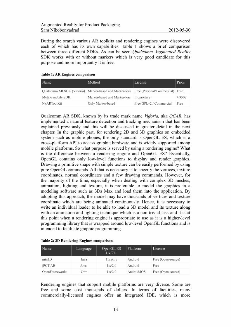
During the search various AR toolkits and rendering engines were discovered each of which has its own capabilities. Table 1 shows a brief comparison between three different SDKs. As can be seen Qualcomm Augmented Reality SDK works with or without markers which is very good candidate for this purpose and more importantly it is free.
Table 1: AR Engines comparison
Name Method License Price
Qualcomm AR SDK (Vuforia) Marker-based and Marker-less Free (Personal/Commercial) Free
Metaio mobile SDK Marker-based and Marker-less Proprietary 4.950€
NyARToolKit Only Marker-based Free GPLv2 / Commercial Free
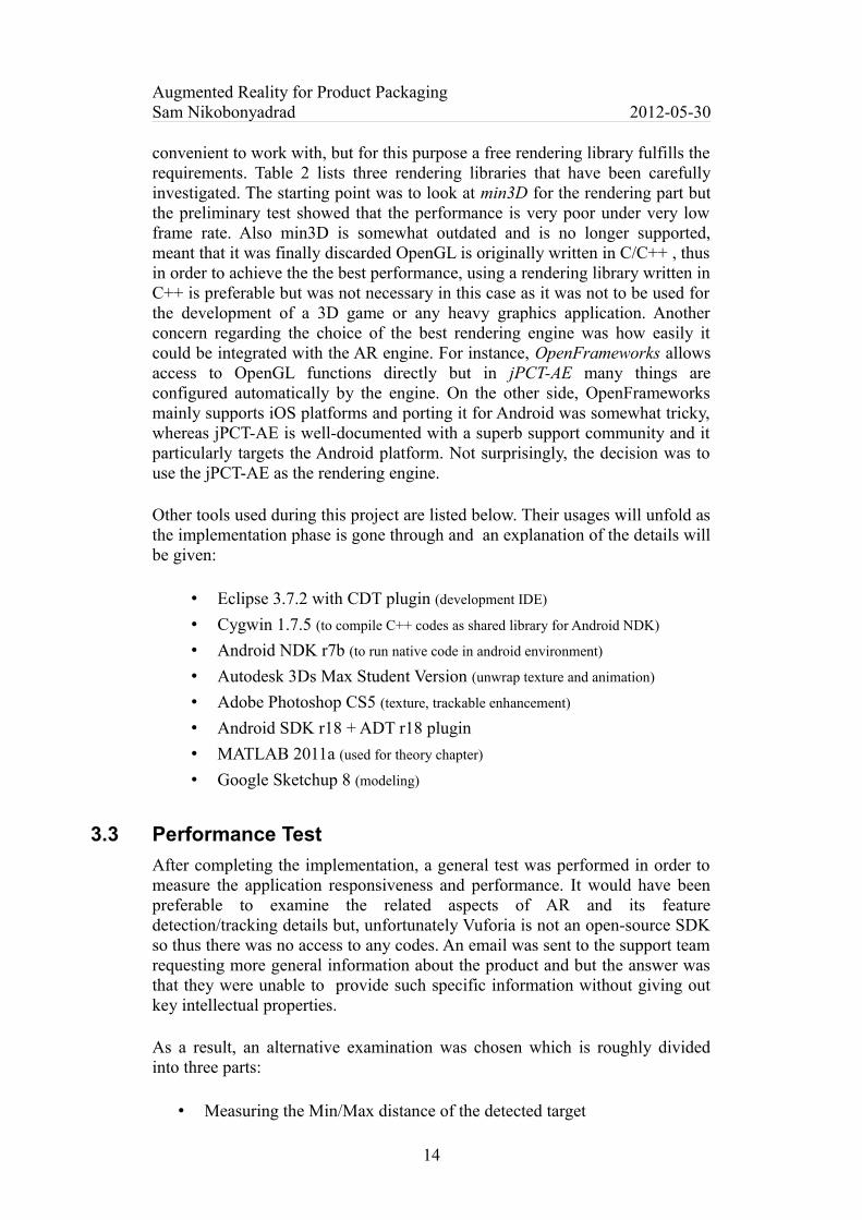
Qualcomm AR SDK, known by its trade mark name Vuforia, aka QCAR, has implemented a natural feature detection and tracking mechanism that has been explained previously and this will be discussed in greater detail in the next chapter. In the graphic part, for rendering 2D and 3D graphics on embedded system such as mobile phones, the only standard is OpenGL ES, which is a cross-platform API to access graphic hardware and is widely supported among mobile platforms. So what purpose is served by using a rendering engine? What is the difference between a rendering engine and OpenGL ES? Essentially, OpenGL contains only low-level functions to display and render graphics. Drawing a primitive shape with simple texture can be easily performed by using pure OpenGL commands. All that is necessary is to specify the vertices, texture coordinates, normal coordinates and a few drawing commands. However, for the majority of the time, especially when dealing with complex 3D meshes, animation, lighting and texture, it is preferable to model the graphics in a modeling software such as 3Ds Max and load them into the application. By adopting this approach, the model may have thousands of vertices and texture coordinate which are being animated continuously. Hence, it is necessary to write an individual loader to be able to load a 3D model and its texture along with an animation and lighting technique which is a non-trivial task and it is at this point when a rendering engine is appropriate to use as it is a higher-level programming library that is wrapped around low-level OpenGL functions and is intended to facilitate graphic programming.
Table 2: 3D Rendering Engines comparison
Name Language OpenGL ES 1.x/2.0
Platform License
min3D Java 1.x only Android Free (Open-source)
jPCT-AE Java 1.x/2.0 Android Free
OpenFrameworks C++ 1.x/2.0 Android/iOS Free (Open-source)
Rendering engines that support mobile platforms are very diverse. Some are free and some cost thousands of dollars. In terms of facilities, many commercially-licensed engines offer an integrated IDE, which is more
13
Augmented Reality for Product PackagingSam Nikobonyadrad 2012-05-30
convenient to work with, but for this purpose a free rendering library fulfills the requirements. Table 2 lists three rendering libraries that have been carefully investigated. The starting point was to look at min3D for the rendering part but the preliminary test showed that the performance is very poor under very low frame rate. Also min3D is somewhat outdated and is no longer supported, meant that it was finally discarded OpenGL is originally written in C/C++ , thus in order to achieve the the best performance, using a rendering library written in C++ is preferable but was not necessary in this case as it was not to be used for the development of a 3D game or any heavy graphics application. Another concern regarding the choice of the best rendering engine was how easily it could be integrated with the AR engine. For instance, OpenFrameworks allows access to OpenGL functions directly but in jPCT-AE many things are configured automatically by the engine. On the other side, OpenFrameworks mainly supports iOS platforms and porting it for Android was somewhat tricky, whereas jPCT-AE is well-documented with a superb support community and it particularly targets the Android platform. Not surprisingly, the decision was to use the jPCT-AE as the rendering engine.
Other tools used during this project are listed below. Their usages will unfold as the implementation phase is gone through and an explanation of the details will be given:
• Eclipse 3.7.2 with CDT plugin (development IDE)
• Cygwin 1.7.5 (to compile C++ codes as shared library for Android NDK)
• Android NDK r7b (to run native code in android environment)
• Autodesk 3Ds Max Student Version (unwrap texture and animation)
• Adobe Photoshop CS5 (texture, trackable enhancement)
• Android SDK r18 + ADT r18 plugin
• MATLAB 2011a (used for theory chapter)
• Google Sketchup 8 (modeling)
3.3 Performance Test
After completing the implementation, a general test was performed in order to measure the application responsiveness and performance. It would have been preferable to examine the related aspects of AR and its feature detection/tracking details but, unfortunately Vuforia is not an open-source SDK so thus there was no access to any codes. An email was sent to the support team requesting more general information about the product and but the answer was that they were unable to provide such specific information without giving out key intellectual properties.
As a result, an alternative examination was chosen which is roughly divided into three parts:
• Measuring the Min/Max distance of the detected target
14

Augmented Reality for Product PackagingSam Nikobonyadrad 2012-05-30
• Measuring the Min/Max horizontal angle of the detected target
• Measuring the loading time for different models (MD2)
Vuforia uses a 5-star rating system for each trackable (reference image) to indicate how well and stable it is to track that particular target. The test was performed on three different trackables with 1, 3 and 5 star rating and to be as accurate as possible, the mobile phone's camera was fixed facing toward the laptop's screen and then the trackables were loaded in Adobe Photoshop. In this way, it was possible to rotate the trackable with an exact unit. For example, in order to find the highest horizontal tilt angle that Vuforia can correctly detect, the trackable remained rotating around the Y coordinate until the model disappeared and then the result was recorded. This procedure has been repeated for all three trackables under similar luminosity and without any reflection or occlusion. For distance calculation Vuforia APIs were used to measure the distance between target and the camera. Additionally, as a complementary task the loading time of 3D models was measured on-the-fly with various amounts of faces and animation key-frames.
15
Augmented Reality for Product PackagingSam Nikobonyadrad 2012-05-30
4 ImplementationThis chapter deals with the steps involved in the process of implementation.
4.1 Overview
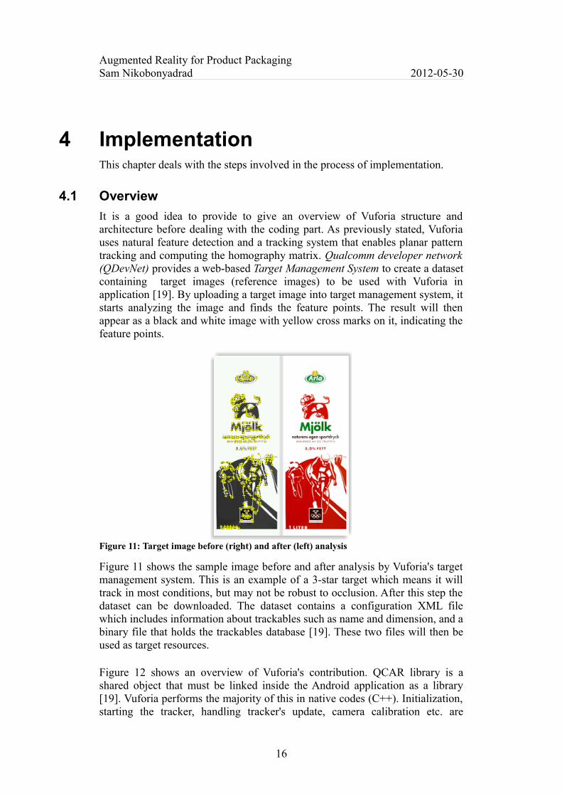
It is a good idea to provide to give an overview of Vuforia structure and architecture before dealing with the coding part. As previously stated, Vuforia uses natural feature detection and a tracking system that enables planar pattern tracking and computing the homography matrix. Qualcomm developer network (QDevNet) provides a web-based Target Management System to create a dataset containing target images (reference images) to be used with Vuforia in application [19]. By uploading a target image into target management system, it starts analyzing the image and finds the feature points. The result will then appear as a black and white image with yellow cross marks on it, indicating the feature points.
Figure 11: Target image before (right) and after (left) analysis
Figure 11 shows the sample image before and after analysis by Vuforia's target management system. This is an example of a 3-star target which means it will track in most conditions, but may not be robust to occlusion. After this step the dataset can be downloaded. The dataset contains a configuration XML file which includes information about trackables such as name and dimension, and a binary file that holds the trackables database [19]. These two files will then be used as target resources.
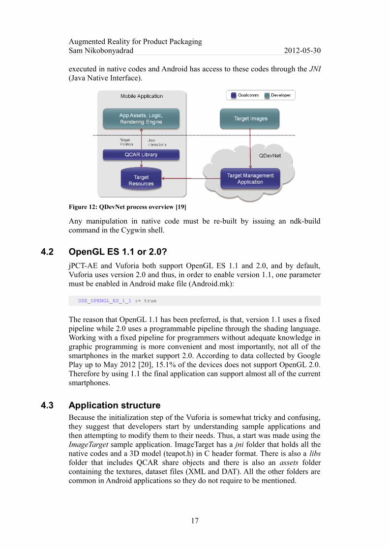
Figure 12 shows an overview of Vuforia's contribution. QCAR library is a shared object that must be linked inside the Android application as a library [19]. Vuforia performs the majority of this in native codes (C++). Initialization, starting the tracker, handling tracker's update, camera calibration etc. are
16
Augmented Reality for Product PackagingSam Nikobonyadrad 2012-05-30
executed in native codes and Android has access to these codes through the JNI (Java Native Interface).
Figure 12: QDevNet process overview [19]
Any manipulation in native code must be re-built by issuing an ndk-build command in the Cygwin shell.
4.2 OpenGL ES 1.1 or 2.0?
jPCT-AE and Vuforia both support OpenGL ES 1.1 and 2.0, and by default, Vuforia uses version 2.0 and thus, in order to enable version 1.1, one parameter must be enabled in Android make file (Android.mk):
USE_OPENGL_ES_1_1 := true
The reason that OpenGL 1.1 has been preferred, is that, version 1.1 uses a fixed pipeline while 2.0 uses a programmable pipeline through the shading language. Working with a fixed pipeline for programmers without adequate knowledge in graphic programming is more convenient and most importantly, not all of the smartphones in the market support 2.0. According to data collected by Google Play up to May 2012 [20], 15.1% of the devices does not support OpenGL 2.0. Therefore by using 1.1 the final application can support almost all of the current smartphones.
4.3 Application structure Because the initialization step of the Vuforia is somewhat tricky and confusing, they suggest that developers start by understanding sample applications and then attempting to modify them to their needs. Thus, a start was made using the ImageTarget sample application. ImageTarget has a jni folder that holds all the native codes and a 3D model (teapot.h) in C header format. There is also a libs folder that includes QCAR share objects and there is also an assets folder containing the textures, dataset files (XML and DAT). All the other folders are common in Android applications so they do not require to be mentioned.
17

Augmented Reality for Product PackagingSam Nikobonyadrad 2012-05-30
4.4 Coding
Vuforia buffers camera frames and performs a pixel conversion and loads it into Tracker [19]. Tracker will then search the pixels to match the correspondences by considering the target's data in dataset. The code snippet below shows some part of the renderFrame() method in native codes which is inside onDrawFrame() method of the GLSurface renderer:
JNIEXPORT void JNICALL
Java_renderFrame(JNIEnv *env, jobject obj) {
// Get the state from QCAR and mark the beginning of a rendering section
QCAR::State state = QCAR::Renderer::getInstance().begin();
// Explicitly render the Video Background
QCAR::Renderer::getInstance().drawVideoBackground();
...
// Did we find any trackables this frame?
for(int tIdx = 0; tIdx < state.getNumActiveTrackables(); tIdx++) {
// Get the trackable:
const QCAR::Trackable* trackable = state.getActiveTrackable(tIdx);
QCAR::Matrix44F modelViewMatrix =QCAR::Tool::convertPose2GLMatrix(trackable->getPose());
As can be seen, QCAR first starts the rendering and then, by calling drawVideoBackground() method, the processed frames are rendered on the GLSurface in the background. Inside the loop, QCAR continuously checks whether or not there is any trackable. As soon as a trackable comes into the camera sight, QCAR computes a 3x4 pose matrix, which is the result of homography or a transformation matrix, and then it converts it to OpenGL 4x4 standard matrix. This matrix is known as the ModelView matrix. In OpenGL pipeline, the ModelView matrix is used to transform object coordinates to eye coordinates. In simpler terms, ModelView determines the position, direction and viewing angle of the camera in OpenGL. It could be stated that, this matrix is the key element of the entire application.
Another important aspect of QCAR is the Projection matrix which determines the clipping volume that shapes the viewing frustum.
Figure 13: Viewing Frustum
18

Augmented Reality for Product PackagingSam Nikobonyadrad 2012-05-30
Figure 13 shows 6 planes (top, bottom, right, left, near, far) forming the frustum volume. Objects outside this volume will be culled. QCAR calculates the projection matrix by calibrating the device camera and specifying the near and far plane. Below is an excerpt from the code:
JNIEXPORT void JNICALL
Java_setProjectionMatrix(JNIEnv *, jobject) {
// Cache the projection matrix:
const QCAR::CameraCalibration& cameraCalibration =QCAR::CameraDevice::getInstance().getCameraCalibration();
projectionMatrix = QCAR::Tool::getProjectionGL(cameraCalibration, 2.0f, 2000.0f);
The ModelView and Projection matrix will be used at a later stage when the rendering part is taken to Java.
4.4.1 GLSurfaceView
The first step involved in integrating jPCT-AE and QCAR is mixing the GLSurfaceView. QCAR uses specific configurations to create a translucent surface view so that while rendering graphics, camera pictures can appear in background. jPCT-AE also applies some configurations to the surface view but fortunately, for the majority, it agrees with QCAR. So this step is started by removing jPCT-AE configurations and running the test application. The first attempt resulted in a black screen with no video picture. To resolve this issue the line below has been removed from renderFrame() method in native code which clears the buffer at the beginning of each frame:
// Clear color and depth buffer
glClear(GL_COLOR_BUFFER_BIT | GL_DEPTH_BUFFER_BIT);
At the same time, the codes below have been added in onDrawFrame() method to clear the buffer in jPCT-AE way with an alpha-enabled color:
private RGBColor mBackground = new RGBColor(0, 0, 0, 0);
mFrameBuffer.clear(mBackground);
This allows the video to render in the background but another problem then arose. This time, a primitive cube with a simple texture has been drawn, but as soon as the video starts rendering, the cube loses shading. After some investigation, it appeared that, according to the documentation [19], QCAR by default makes some changes to the OpenGL state in its initialization. Therefore by overriding the default settings in onDrawFrame() method the problem was solved.
Figure 14: No shading (left), Expected result with shading (right)
19
Augmented Reality for Product PackagingSam Nikobonyadrad 2012-05-30
As can be seen in Figure 14, after restoring the default setting, the cube is now shaded correctly. Below is an excerpt from the codes:
public void onDrawFrame(GL10 gl) {
...
// Overrides the default QCAR initialization settings
gl11.glEnable(GL11.GL_DEPTH_TEST);
gl11.glEnable(GL11.GL_CULL_FACE);
gl11.glTexEnvi(GL11.GL_TEXTURE_ENV, GL11.GL_TEXTURE_ENV_MODE, GL11.GL_MODULATE);
gl11.glEnable(GL11.GL_LIGHTING);
gl11.glEnable(GL11.GL_BLEND);
4.4.2 ModelView Matrix
When using OpenGL commands, it is easy to load the ModelView matrix simply by changing the matrix mode to GL_MODELVIEW and then calling glLoadMatrixf(ModelView). But rendering engines generally use a different concept, known as Camera, to simulate eye position and direction. jPCT-AE is no exception, so in order to use the ModelView matrix generated by QCAR, the matrix must be brought from native codes back to Java and then be used to set the camera position and orientation. Below are the steps taken to pass a 4x4 float matrix from native codes to Java:
// Passing the Modelview matrix up to Java
jclass javaClass = env->GetObjectClass(obj);
jfloatArray modelviewArray = env->NewFloatArray(16);
jmethodID method = env->GetMethodID(javaClass, "updateModelviewMatrix", "([F)V");
...
// Passing the ModelView matrix up to Java (cont.)
env->SetFloatArrayRegion(modelviewArray, 0, 16, modelViewMatrix.data);
env->CallObjectMethod(obj, method, modelviewArray);
env->DeleteLocalRef(modelviewArray);
Here the class of Java object is obtained by calling the GetObjectClass() method of the JNI interface pointer (env) and then a Java array of 16 floats is created. Notice the fourth line of the code, UpdateModelviewMatrix which is a method to handle the model view matrix in Java. The method ID is firstly retrieved as the array is attached to env, the Java method is called from native code and the array will be passed. In the renderer class, the matrix can be directly applied to the camera instance. The array must firstly be converted back to a matrix and then set for the camera:
mMatrix.setDump(mModelviewArray); // Convert a float array into 4x4 matrix
mCamera.setBack(mMatrix); // Sets the camera back matrix
20

Augmented Reality for Product PackagingSam Nikobonyadrad 2012-05-30
The approach is very straightforward but there is a significant problem in that the QCAR uses a right-handed coordinate system meaning that the X positive goes right, the Y positive goes up and the Z positive comes out of screen. The jPCT-AE, however, uses a different coordinate system such that, the X positive goes right, the Y positive goes down and the Z positive goes into the screen. Therefore ModelView is useless until it has been converted in order to satisfy the new coordinate system. There is a mathematical method to change the coordinate but, as can be noted from in Figure 15, the X axis is identical in both coordinates, hence 180 degrees rotation around X axis has the same effect as changing the coordinate system.
Figure 15: Coordinate system in QCAR and jPCT-AE
Luckily, QCAR has provided a SampleUtils class, which is designed for simple mathematical manipulation on matrices. Below is the code that rotates the ModelView matrix around X axis:
// coordinates from right-handed to jPCT (upside-down)
SampleUtils::rotatePoseMatrix(180.0f, 1.0f, 0, 0, &modelViewMatrix.data[0]);
Now with that change, the cube moves relatively to the image targets.
4.4.3 Projection Matrix
For projection matrix, similar steps could have been taken, as those for the model view matrix, in order to bring it to Java but jPCT-AE does not allow it to be used directly. It is automatically created at runtime using the current camera settings. So using the projection matrix is not useful but instead, it is possible to calculate the FOV (Field of View) of the camera by obtaining the camera calibration size and focal length. According to Paul Bourke'w website [21] the mathematics formula is:
Horizontal FOV =2 arctan (0.5 Width
Focal Length) (1)
where "Width" is the horizontal width of the camera calibration plane. The codes below show how the FOV is calculated:
JNIEXPORT jfloat JNICALL
21
X
X
Y
Y
Z
Z
jPCT-AEQCAR (Vuforia)
Augmented Reality for Product PackagingSam Nikobonyadrad 2012-05-30
Java_getProjectionMatrix(JNIEnv *env, jobject obj) {
const QCAR::CameraCalibration& cameraCalibration = QCAR::CameraDevice::getInstance().getCameraCalibration();
// Size and Focal length for calculating the Field of View (FOV)
QCAR::Vec2F sizeVector = cameraCalibration.getSize();
QCAR::Vec2F focalVector = cameraCalibration.getFocalLength();
// Calculation of FOV
FOV = 2 * atan (0.5 * sizeVector.data[0] / focalVector.data[0]);
return FOV;
And then in Java code it is used to configure the camera:
// Retrieve the Field of View from QCAR
mFieldofView = getProjectionMatrix();
...
mCamera.setFOV(mFieldofView);
4.4.4 Loading 3D models asynchronously
When video game are played using a mobile phone, it may be noticeable that there is a few seconds loading delay before each level of game in which a loading splash screen or a loading progress is shown and it is at this point that all the materials, models, textures and animations are being loaded into memory. This is the common approach used by game developers to preserve the performance and avoid loading extras at runtime. Since, in this case, an application is being developed for a packaging company that potentially has many products and is willing to use a specific model, texture and animation for each product, loading all the models at once is not practical, especially with the very limited amount of memory on mobile devices. At first an attempt was made to load the sample model before start the rendering, but it caused 10 seconds delay before QCAR can render the video background which is fairly annoying for the users as if all the models and related material are loaded at once, even if the memory allows this, it will take a significant amount of time. Consequently, a mechanism to load models on-the-fly was necessary. For this reason, an AsyncTask has been utilized to load models in background. Below is an excerpt from the codes:
private class ModelLoader extends AsyncTask<Void, Void, Void> {
@Override
protected Void doInBackground(Void... params) {
// Loading an animated MD2 model from asset folder
try {
mModel = Loader.loadMD2(mContext.getAssets().open("Tetra.md2"),2.8f);
} catch (IOException e) {
...
@Override
22

Augmented Reality for Product PackagingSam Nikobonyadrad 2012-05-30
protected void onPostExecute(Void result) {
// Model settings
mModel.setTexture("texture");
mModel.setLighting(Object3D.LIGHTING_ALL_ENABLED);
mModel.strip();
mWorld.addObject(mModel); // Adds model to the world object
4.4.5 Memory usage improvement
jPCT-AE uses a Texture Manager class to store the loaded textures and organize them, but the texture remains in memory if it is not deleted explicitly. The same is true for loaded models. As seen previously, jPCT-AE supports MD2 models with keyframe animation. Each model, together with its texture and animation, will take up some memory space and if it is not used carefully the Java heap size will eventually be exhausted and this will interrupt the application. To solve this problem the cleanRenderer() method has been defined for the renderer class to be called on onDestroy() event of GLSUrfaceView.
protected void cleanRenderer() {
TextureManager.getInstance().removeTexture("texture");
mModel = null;
mFrameBuffer.freeMemory();
mFrameBuffer.dispose();
mFrameBuffer = null;
mWorld.dispose();
mWorld = null;
Loader.clearCache();
}
In the above code, the texture is firstly removed from the texture manager, which is sufficient to unload it from GPU memory. Then it continues freeing frame buffer memory and disposing of the world object. Lastly. after clearing the loader's cache, the memory is usable for the next time.
4.5 Modeling
As mentioned previously, jPCT-AE supports MD2 format. MD2 is an old 3D format introduced by id Software when releasing Quake 2 in November 1997 [22]. It is lightweight and it supports frame-by-frame animation, which makes it suitable for mobile devices. It would have been preferable to use a free MD2 file downloaded from the Internet in the application, but unfortunately freely-available models, were extremely detailed with too many faces (triangles) which is not a good choice to use in a mobile application. Consequently, this part was modeled by the author. Since a milk package has been used as the target image, the decision was made to model a 3D milk tetra pak for better presentation and testing purpose.
23
Augmented Reality for Product PackagingSam Nikobonyadrad 2012-05-30
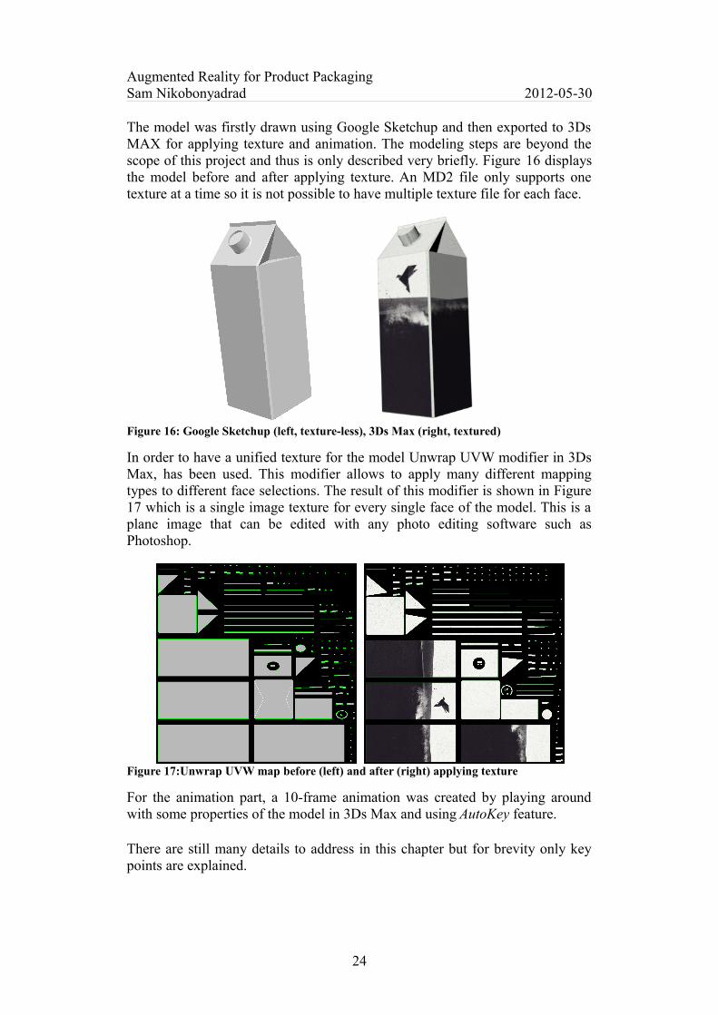
The model was firstly drawn using Google Sketchup and then exported to 3Ds MAX for applying texture and animation. The modeling steps are beyond the scope of this project and thus is only described very briefly. Figure 16 displays the model before and after applying texture. An MD2 file only supports one texture at a time so it is not possible to have multiple texture file for each face.
Figure 16: Google Sketchup (left, texture-less), 3Ds Max (right, textured)
In order to have a unified texture for the model Unwrap UVW modifier in 3Ds Max, has been used. This modifier allows to apply many different mapping types to different face selections. The result of this modifier is shown in Figure 17 which is a single image texture for every single face of the model. This is a plane image that can be edited with any photo editing software such as Photoshop.
Figure 17:Unwrap UVW map before (left) and after (right) applying texture
For the animation part, a 10-frame animation was created by playing around with some properties of the model in 3Ds Max and using AutoKey feature.
There are still many details to address in this chapter but for brevity only key points are explained.
24
Augmented Reality for Product PackagingSam Nikobonyadrad 2012-05-30
5 ResultsThis chapter presents some screenshots of the actual application in action, to see how realistically the model is being superimposed. In addition, the result of evaluation part including, measuring the efficient distance and angle along with the loading time for different models will be shown.
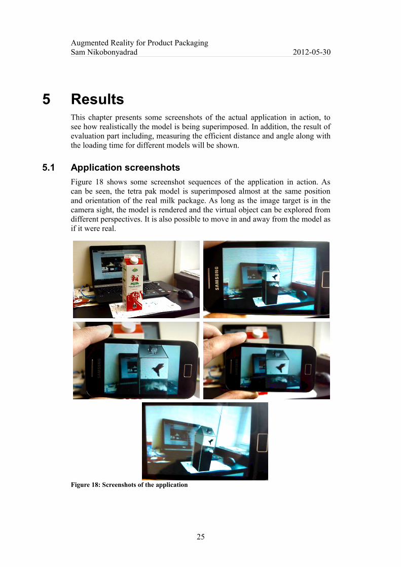
5.1 Application screenshots
Figure 18 shows some screenshot sequences of the application in action. As can be seen, the tetra pak model is superimposed almost at the same position and orientation of the real milk package. As long as the image target is in the camera sight, the model is rendered and the virtual object can be explored from different perspectives. It is also possible to move in and away from the model as if it were real.
Figure 18: Screenshots of the application
25
Augmented Reality for Product PackagingSam Nikobonyadrad 2012-05-30
5.2 Efficient distance
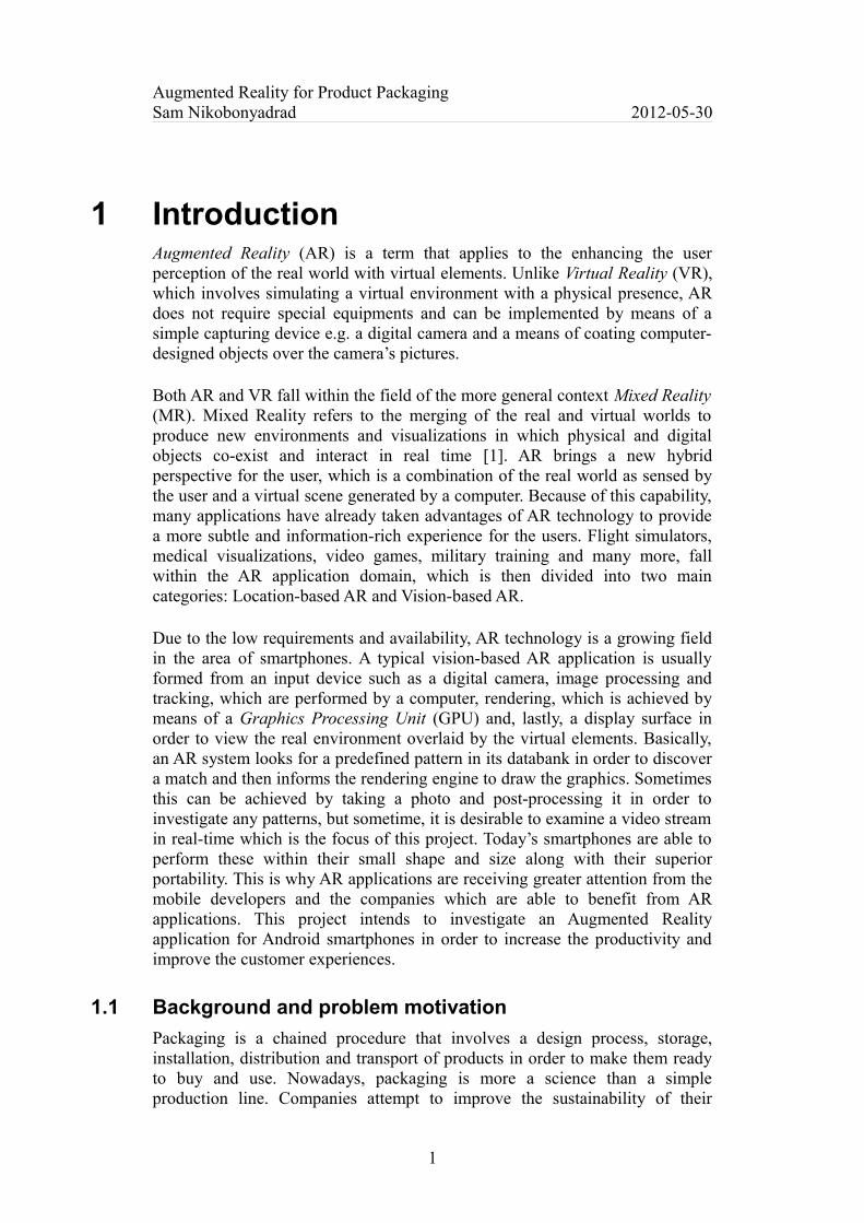
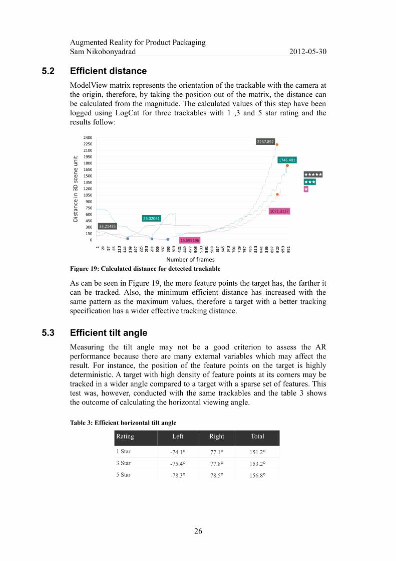
ModelView matrix represents the orientation of the trackable with the camera at the origin, therefore, by taking the position out of the matrix, the distance can be calculated from the magnitude. The calculated values of this step have been logged using LogCat for three trackables with 1 ,3 and 5 star rating and the results follow:
Figure 19: Calculated distance for detected trackable
As can be seen in Figure 19, the more feature points the target has, the farther it can be tracked. Also, the minimum efficient distance has increased with the same pattern as the maximum values, therefore a target with a better tracking specification has a wider effective tracking distance.
5.3 Efficient tilt angle
Measuring the tilt angle may not be a good criterion to assess the AR performance because there are many external variables which may affect the result. For instance, the position of the feature points on the target is highly deterministic. A target with high density of feature points at its corners may be tracked in a wider angle compared to a target with a sparse set of features. This test was, however, conducted with the same trackables and the table 3 shows the outcome of calculating the horizontal viewing angle.
Table 3: Efficient horizontal tilt angle
Rating Left Right Total
1 Star -74.1º 77.1º 151.2º
3 Star -75.4º 77.8º 153.2º
5 Star -78.3º 78.5º 156.8º
26
2237.892
33.21485
1746.401
26.02061
1071.3127
15.59919601 5 03 0 04 5 06 0 07 5 09 0 0
1 0 501 2 001 3 501 5 001 6 501 8 001 9 502 1 002 2 502 4 00
Number of frames

Augmented Reality for Product PackagingSam Nikobonyadrad 2012-05-30
Not surprisingly, the more feature points can lead to a wider tracking angle. Because this work deals with planar targets, the result for the vertical angle must agree with what has been achieved here. In some parts of the project it was necessary to compute the amount of target's pixel in the camera images. That experience proved that Vuforia requires a range of 80-110 pixels worth of the target to be able to track it.
5.4 3D Model loading time
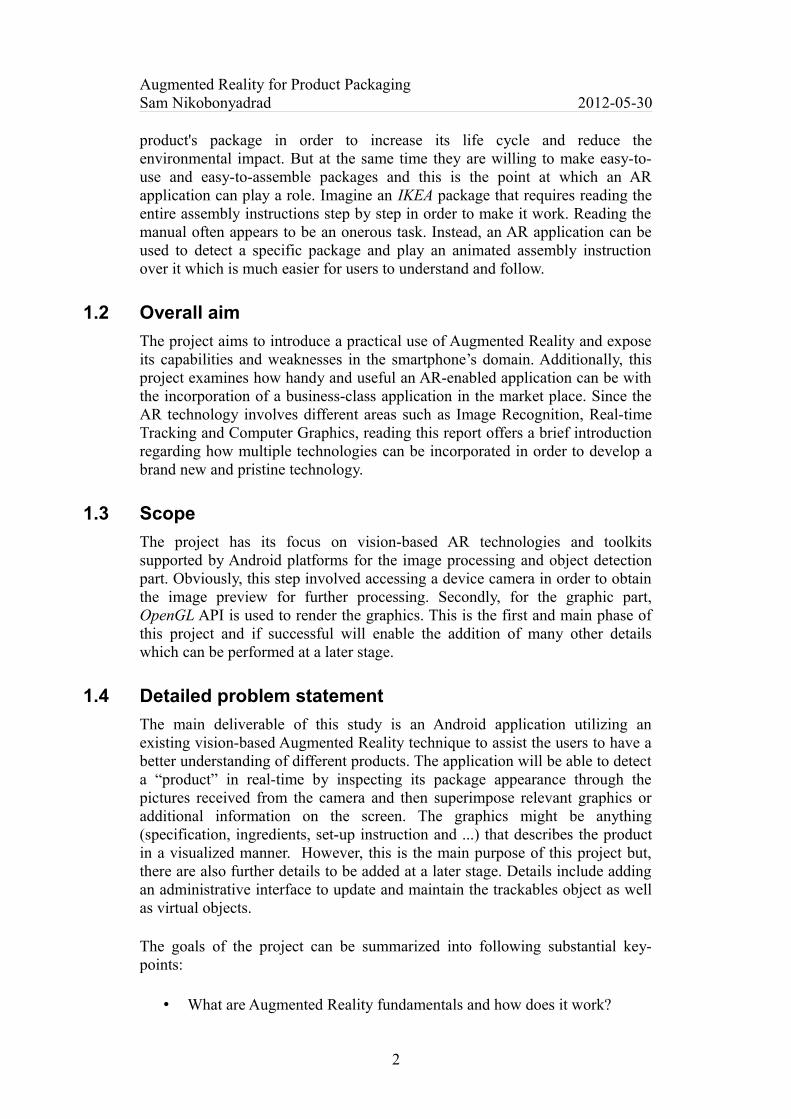
For measuring the loading time, the test has been conducted on four MD2 models at runtime, meaning that Vuforia is rendering the camera images on the GLSurface view. Models were varied in terms of the number of faces and animation's frames. As Figure 20 reveals, the result is as was expected in that more complex meshes take more time to load. Also, the animation used in 2nd
and 3rd models is completely identical and when it is being played there is no significant difference or any sort of lag. It has to be mentioned that these times are regardless of the texture. Loading texture alone takes some time based on its size and color depth.
Figure 20: Models loading time at runtime (second)
All of these tests are conducted on a mid-range cellphone powered by Android 2.3.3. It is certainly the case that the, device's hardware can have a huge impact on the performance and loading time. The amount of data used in this test contains the information that OpenGL requires to draw a graphic in 3D space. These include vertices, texture coordinates, index vertex buffer, normal coordinates and key-frame animation.
27
2.1 s
6.1 s
8.5 s
48.7 s
0 10 20 30 40 50 60
Time in second
Faces: 3643 Animation: none
Faces: 382 Animation: 60 frames
Faces: 382 Animation: 10 frames
Faces: 6 Animation: 10 frames
Augmented Reality for Product PackagingSam Nikobonyadrad 2012-05-30
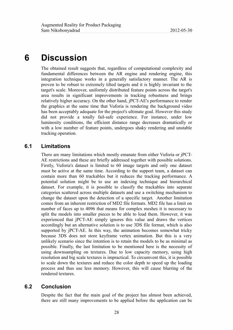
6 DiscussionThe obtained result suggests that, regardless of computational complexity and fundamental differences between the AR engine and rendering engine, this integration technique works in a generally satisfactory manner. The AR is proven to be robust to extremely tilted targets and it is highly invariant to the target's scale. Moreover, uniformly distributed feature points across the target's area results in significant improvements in tracking robustness and brings relatively higher accuracy. On the other hand, jPCT-AE's performance to render the graphics at the same time that Vuforia is rendering the background video has been acceptably adequate for the project's ultimate goal. However this study did not provide a totally fail-safe experience. For instance, under low luminosity conditions, the efficient distance range decreases dramatically or with a low number of feature points, undergoes shaky rendering and unstable tracking operation.
6.1 Limitations
There are many limitations which mostly emanate from either Vuforia or jPCT-AE restrictions and these are briefly addressed together with possible solutions. Firstly, Vuforia's dataset is limited to 60 image targets and only one dataset must be active at the same time. According to the support team, a dataset can contain more than 60 trackables but it reduces the tracking performance. A potential solution might be to use an indexing technique and hierarchical dataset. For example, it is possible to classify the trackables into separate categories scattered across multiple datasets and use a switching mechanism to change the dataset upon the detection of a specific target. Another limitation comes from an inherent restriction of MD2 file formats. MD2 file has a limit on number of faces up to 4096 that means for complex meshes it is necessary to split the models into smaller pieces to be able to load them. However, it was experienced that jPCT-AE simply ignores this value and draws the vertices accordingly but an alternative solution is to use 3DS file format, which is also supported by jPCT-AE. In this way, the animation becomes somewhat tricky because 3DS does not store keyframe vertex animation. But this is a very unlikely scenario since the intention is to retain the models to be as minimal as possible. Finally, the last limitation to be mentioned here is the necessity of using downsampling on textures. Due to low capacity memory, using high resolution and big scale textures is impractical. To circumvent this, it is possible to scale down the textures and reduce the color depth to speed up the loading process and thus use less memory. However, this will cause blurring of the rendered textures.
6.2 Conclusion
Despite the fact that the main goal of the project has almost been achieved, there are still many improvements to be applied before the application can be
28

Augmented Reality for Product PackagingSam Nikobonyadrad 2012-05-30
published on a public market. As it has been stated, in the introduction chapter, the application requires an administrative interface to update and manage the graphics and trackables. This usually involves some I/O operations to read and write files. It would also be possible to employ a web service to frequently update the dataset and graphics over the air. Additionally, adding sound or an interaction method to the application may ameliorate the user's experience.
29
Augmented Reality for Product PackagingSam Nikobonyadrad 2012-05-30
References
[1] Wikipedia, “Mixed Reality” http://en.wikipedia.org/wiki/Mixed_realityRetrieved 2012-04-22
[2] Wikipedia, “Computer Vision”http://en.wikipedia.org/wiki/Computer_visionRetrieved 2012-05-17
[3] R. Szeliski, Computer Vision: Algorithms and Applications, New York: Springer, 2010
[4] Wikipedia, “Augmented Reality”http://en.wikipedia.org/wiki/Augmented_realityRetrieved 2012-05-17
[5] B. Zitova´, J. Flusser, “Image Registration Methods: A Survey”, Image and Vision Computing, (Elsevier) 21 (2003), pp. 977-1000.
[6] A. Goshtasby, Image Registration: Principles, Tools and Methods, New York: Springer, 2012
[7] Wikipedia, “Image Registration”http://en.wikipedia.org/wiki/Image_registrationRetrieved 2012-05-18
[8] Florent Brunet, “General Points on Image Registration”http://www.brnt.eu/phd/node20.htmlRetrieved 2012-05-18
[9] Wikipedia, “Feature Detection”http://en.wikipedia.org/wiki/Feature_detection_(computer_vision)Retrieved 2012-05-22
[10] Wikipedia, “SURF”http://en.wikipedia.org/wiki/SURFRetrieved 2012-05-23
[11] M. Nixon, A. Aguado, Feature Extraction and Image Processing, Second Edition, London: Elsevier Ltd, 2008
[12] T. Kobayashi, N. Otsu, “Motion recognition using local auto-correlation of space–time gradients”, Pattern Recognition Letters, (Elsevier) 33 (2012) pp. 1188–1195
30
Augmented Reality for Product PackagingSam Nikobonyadrad 2012-05-30
[13] MathWorks 2011, MATLAB R2011a Documentation, Computer Vision, Image Registration. Massachusetts, USA: The MathWorks, Inc
[14] M. Haller, “Emerging Technologies of Augmented Reality: Interfaces and Design”, PA: IGI Global, 2006
[15] Wikipedia, “Optical Flow”http://en.wikipedia.org/wiki/Optical_flowRetrieved 2012-05-25
[16] Christian Doppler Laboratory, “Hand-held Augmented Reality”http://handheldar.icg.tugraz.at/highspeed_nft.phpRetrieved 2012-05-25
[17] D. Wagner, G. Reitmayr, A. Mulloni, T. Drummond, D. Schmalstieg, “Pose Tracking from Natural Features on Mobile Phones” (2008) ISMAR2008, Cambridge, UK
[18] M. Özuysal, M. Calonder, V. Lepetit, P. Fua, “Fast Keypoint Recognition using Random Ferns” (2010) Ecole Polytechnique Fédérale de Lausanne (EPFL), Lausanne, Switzerland
[19] QDevNet Qualcomm developer network, “AR Developer Guide”https://ar.qualcomm.at/qdevnet/developer_guideRetrieved 2012-05-28
[20] Android Developers | OpenGL ES Versionhttp://developer.android.com/resources/dashboard/opengl.htmlRetrieved 2012-05-28
[21] Paul Bourke, “Field of view and focal length”http://paulbourke.net/miscellaneous/lens/Retrieved 2012-04-29
[22] MD2 File Format (Quake 2's models)http://tfc.duke.free.fr/coding/md2-specs-en.htmlRetrieved 2012-05-29
31